EP3584172B1 - Procédé et système permettant de guider un pilote de l'approche d'un aéronef sur une position d'arrêt à un stand - Google Patents
Procédé et système permettant de guider un pilote de l'approche d'un aéronef sur une position d'arrêt à un stand Download PDFInfo
- Publication number
- EP3584172B1 EP3584172B1 EP18178233.5A EP18178233A EP3584172B1 EP 3584172 B1 EP3584172 B1 EP 3584172B1 EP 18178233 A EP18178233 A EP 18178233A EP 3584172 B1 EP3584172 B1 EP 3584172B1
- Authority
- EP
- European Patent Office
- Prior art keywords
- area
- aircraft
- stand
- subsection
- approaching
- Prior art date
- Legal status (The legal status is an assumption and is not a legal conclusion. Google has not performed a legal analysis and makes no representation as to the accuracy of the status listed.)
- Active
Links
Images


Classifications
-
- B—PERFORMING OPERATIONS; TRANSPORTING
- B64—AIRCRAFT; AVIATION; COSMONAUTICS
- B64F—GROUND OR AIRCRAFT-CARRIER-DECK INSTALLATIONS SPECIALLY ADAPTED FOR USE IN CONNECTION WITH AIRCRAFT; DESIGNING, MANUFACTURING, ASSEMBLING, CLEANING, MAINTAINING OR REPAIRING AIRCRAFT, NOT OTHERWISE PROVIDED FOR; HANDLING, TRANSPORTING, TESTING OR INSPECTING AIRCRAFT COMPONENTS, NOT OTHERWISE PROVIDED FOR
- B64F1/00—Ground or aircraft-carrier-deck installations
- B64F1/002—Taxiing aids
-
- B—PERFORMING OPERATIONS; TRANSPORTING
- B64—AIRCRAFT; AVIATION; COSMONAUTICS
- B64F—GROUND OR AIRCRAFT-CARRIER-DECK INSTALLATIONS SPECIALLY ADAPTED FOR USE IN CONNECTION WITH AIRCRAFT; DESIGNING, MANUFACTURING, ASSEMBLING, CLEANING, MAINTAINING OR REPAIRING AIRCRAFT, NOT OTHERWISE PROVIDED FOR; HANDLING, TRANSPORTING, TESTING OR INSPECTING AIRCRAFT COMPONENTS, NOT OTHERWISE PROVIDED FOR
- B64F1/00—Ground or aircraft-carrier-deck installations
-
- G—PHYSICS
- G01—MEASURING; TESTING
- G01S—RADIO DIRECTION-FINDING; RADIO NAVIGATION; DETERMINING DISTANCE OR VELOCITY BY USE OF RADIO WAVES; LOCATING OR PRESENCE-DETECTING BY USE OF THE REFLECTION OR RERADIATION OF RADIO WAVES; ANALOGOUS ARRANGEMENTS USING OTHER WAVES
- G01S17/00—Systems using the reflection or reradiation of electromagnetic waves other than radio waves, e.g. lidar systems
- G01S17/02—Systems using the reflection of electromagnetic waves other than radio waves
- G01S17/06—Systems determining position data of a target
- G01S17/42—Simultaneous measurement of distance and other co-ordinates
-
- G—PHYSICS
- G01—MEASURING; TESTING
- G01S—RADIO DIRECTION-FINDING; RADIO NAVIGATION; DETERMINING DISTANCE OR VELOCITY BY USE OF RADIO WAVES; LOCATING OR PRESENCE-DETECTING BY USE OF THE REFLECTION OR RERADIATION OF RADIO WAVES; ANALOGOUS ARRANGEMENTS USING OTHER WAVES
- G01S17/00—Systems using the reflection or reradiation of electromagnetic waves other than radio waves, e.g. lidar systems
- G01S17/88—Lidar systems specially adapted for specific applications
- G01S17/93—Lidar systems specially adapted for specific applications for anti-collision purposes
-
- G—PHYSICS
- G08—SIGNALLING
- G08G—TRAFFIC CONTROL SYSTEMS
- G08G5/00—Traffic control systems for aircraft
-
- G—PHYSICS
- G08—SIGNALLING
- G08G—TRAFFIC CONTROL SYSTEMS
- G08G5/00—Traffic control systems for aircraft
- G08G5/20—Arrangements for acquiring, generating, sharing or displaying traffic information
- G08G5/22—Arrangements for acquiring, generating, sharing or displaying traffic information located on the ground
-
- G—PHYSICS
- G08—SIGNALLING
- G08G—TRAFFIC CONTROL SYSTEMS
- G08G5/00—Traffic control systems for aircraft
- G08G5/50—Navigation or guidance aids
- G08G5/51—Navigation or guidance aids for control when on the ground, e.g. taxiing or rolling
-
- G—PHYSICS
- G08—SIGNALLING
- G08G—TRAFFIC CONTROL SYSTEMS
- G08G5/00—Traffic control systems for aircraft
- G08G5/70—Arrangements for monitoring traffic-related situations or conditions
- G08G5/72—Arrangements for monitoring traffic-related situations or conditions for monitoring traffic
- G08G5/727—Arrangements for monitoring traffic-related situations or conditions for monitoring traffic from a ground station
-
- G—PHYSICS
- G01—MEASURING; TESTING
- G01S—RADIO DIRECTION-FINDING; RADIO NAVIGATION; DETERMINING DISTANCE OR VELOCITY BY USE OF RADIO WAVES; LOCATING OR PRESENCE-DETECTING BY USE OF THE REFLECTION OR RERADIATION OF RADIO WAVES; ANALOGOUS ARRANGEMENTS USING OTHER WAVES
- G01S13/00—Systems using the reflection or reradiation of radio waves, e.g. radar systems; Analogous systems using reflection or reradiation of waves whose nature or wavelength is irrelevant or unspecified
- G01S13/88—Radar or analogous systems specially adapted for specific applications
- G01S13/93—Radar or analogous systems specially adapted for specific applications for anti-collision purposes
- G01S13/933—Radar or analogous systems specially adapted for specific applications for anti-collision purposes of aircraft or spacecraft
- G01S13/934—Radar or analogous systems specially adapted for specific applications for anti-collision purposes of aircraft or spacecraft on airport surfaces, e.g. while taxiing
-
- Y—GENERAL TAGGING OF NEW TECHNOLOGICAL DEVELOPMENTS; GENERAL TAGGING OF CROSS-SECTIONAL TECHNOLOGIES SPANNING OVER SEVERAL SECTIONS OF THE IPC; TECHNICAL SUBJECTS COVERED BY FORMER USPC CROSS-REFERENCE ART COLLECTIONS [XRACs] AND DIGESTS
- Y02—TECHNOLOGIES OR APPLICATIONS FOR MITIGATION OR ADAPTATION AGAINST CLIMATE CHANGE
- Y02T—CLIMATE CHANGE MITIGATION TECHNOLOGIES RELATED TO TRANSPORTATION
- Y02T50/00—Aeronautics or air transport
- Y02T50/80—Energy efficient operational measures, e.g. ground operations or mission management
Definitions
- the present invention relates to a method for guiding a pilot of an approaching aircraft to a stop position at a stand.
- the invention further relates to an aircraft docking system.
- the dimensions of the aircrafts also have an influence on the docking of aircrafts to a stand at the airport.
- the infrastructure has to be rebuilt to accommodate for the physical dimensions of the aircrafts, but in other cases, the physical dimensions are enough for the aircrafts to fit.
- the problem may instead be related to achieving a safe docking of the aircrafts. Larger aircrafts have larger distance between their wheels, thus resulting in a larger turning radius. Moreover, the wing tip to wing tip distance is usually larger.
- aircraft docking systems arranged locally at the stands of the airport, wherein each aircraft docking system is configured to aid the pilot, and sometimes also the ground crew, in receiving the aircraft at the stand in a safe and reliable way.
- aircraft docking systems comprise means for establishing a position of the aircraft as it approaches the stand, said means often being a remote sensing detection system, such as a laser scanning system or a radar based system.
- the aircraft docking systems known in the art are configured to analyze position data from the aircraft, and potentially also other input parameters, and, based on the parameters, make a decision whether to allow docking or not. Based on the decision, information is shown on a display at the stand in clear view of the pilot, instructing the pilot of which action to take.
- Aircraft docking systems are known in the art.
- WO 01/35327 A1 discloses an aircraft identification and docking guidance system utilizing a laser range finder (LRF) to identify an aircraft approaching a gate.
- LRF laser range finder
- the LRF is directed at the aircraft, and from the echoes, a profile is derived and compared to known profiles.
- US 2008/157947 A1 discloses a radio frequency identification (RFID) tag-based system and method for guiding an aircraft to a stopping position.
- RFID tags are typically disposed in the ground and may be sensed by an RFID sensor disposed on the aircraft.
- EP 3 222 529 A1 discloses an aircraft docking system comprising a light based verification and positioning system adapted to scan a volume in connection to a stand, wherein the light based verification and positioning system is further adapted to control the extension of the scanned volume based on the received surveillance data.
- a problem with known methods and systems is that they are not adapted to handle the larger aircrafts of increasing importance today. Even if the physical dimensions of the aircrafts would fit the stand, the aircraft docking systems, and the methods implemented therein are not adapted to handle the docking in a correct way which may lead to high degree of interruptions during docking, or even accidents.
- the method makes use of the underlying knowledge that an aircraft of certain dimensions and relative distances between its wheels has a predefined maneuverability. This means that, if an approaching aircraft enters the stand area in a certain way, the aircraft docking system does not need to know exactly how the aircraft is located in relation to the stand. One position of the aircraft, such as the position of the nose of the aircraft, is enough for the aircraft docking system to be able to predict whether or not the aircraft is likely to succeed an attempted approach to the stand. The decision is taken after the aircraft has entered the first area. Then, dependent on which portion of the first area in which the monitored position of the aircraft is entering (i.e. inside or outside the subsection of the first area), the decision may be taken to allow or stop an approach.
- the method may be advantageous as it allows for providing a safer docking, especially for aircrafts of larger dimensions or automated safety from a wing clearance perspective at any stand designed for any aircraft dimensions, i.e. two adjacent narrow-bodied stands.
- the wing tip clearance between neighboring aircrafts must be 7.5 meters unless the stand areas are monitored by aircraft docking systems to assist in the parking.
- the disclosed method may allow for new, larger, types of aircrafts to be parked at stands originally not designed and constructed to house such aircraft types.
- the method may be advantageous in situations where an aircraft for some reason has entered a stand area along a wrong lead-in line. The pilot may attempt to adjust the course of the aircraft to compensate, but in some cases the attempt may be unsuccessful, as the dimensions of the aircraft is too large for successful repositioning within the area available.
- the method may allow for a more flexible docking methodology at the airport.
- the flexibility has much to do with the ease by which the first area and the subsection thereof may be redefined dependent on the situation. Even if the infrastructure at an airport stand to some degree is fixed, and may be considered predefined, some parts of the infrastructure are not, such as e.g. a movable airport boarding bridge. By adjusting the first area and/or the subsection thereof, structural changes at the stand area may be accounted for.
- the system may adjust the first area and the subsection thereof dependent on which of the lead-in lines the approaching aircraft is assigned to follow. Should the pilot mistakenly drive the aircraft following the wrong lead-in line, the aircraft may enter the first area outside of the subsection of the first area, whereby the pilot would be instructed to stop the aircraft.
- the first area is defined so as to enclose the stop position.
- the first area may also enclose a portion of the lead-in line.
- the first area then extends along the approach direction.
- the approach direction may coincide with the direction of a linear portion of the lead-in line in the vicinity of the stop position.
- the first area defines a front boundary facing the approaching aircraft.
- the first area may be geometrically easy to define, such as a rectangle. In such a case, the first area will have four sides, one of which being the front boundary.
- the first area may, however, have any shape.
- the subsection of the first area encloses the stop position and extends along the approach direction to meet a portion of the front boundary of the first area.
- the subsection may further enclose a portion of the lead-in line.
- the subsection encloses the whole portion of the lead-in line enclosed by the first area.
- the subsection may be rectangular-shaped and defined symmetrically in relation to the lead-in line.
- the subsection shares a portion of its boundaries with the first area. This implies that the shared portion is a portion of the front boundary.
- the second area is defined outside of the first area.
- the second area thus extends outwardly from the front boundary of the first area.
- the second area defines a front boundary of its own.
- the front boundary of the second area also faces the approaching aircraft.
- the approaching aircraft will first cross the front boundary of the second area to enter the second area, and, later, pass the front boundary of the first area to enter the first area.
- the first area and the second area share a portion of their boundaries.
- the second area shares a portion of its boundaries corresponding to the front boundary of the first area. This implies that the first area and the second area may be in abutment with each other all along the front boundary of the first area.
- the control unit may be configured to receive identification data pertaining to the type of the approaching aircraft. Using the identification data, the aircraft docking system may determine the dimensions of the aircraft for example from a database at the airport with which database the aircraft docking system is operatively connected. It is also conceivable that the aircraft docking system has dimensions of aircraft types stored locally. The aircraft docking system may for example have predefined coordinates of the first area and the subsection thereof stored in a memory of the aircraft docking system, thus allowing for the control unit to retrieve, from said memory, corresponding coordinates for a particular aircraft type.
- the first area and the subsection thereof may differ between different aircrafts, different stands, different approach directions etc. For example, if a Boeing 747 is approaching a particular stand from a left side, the dimensions and positions of the first area and subsection thereof will be different than if an Airbus A380 is approaching the same stand from a right side.
- the extension of the first area and/or the extension of the subsection of the first area may be determined based upon one or more from the list of: dimensions of an aircraft expected to approach the stand, dimensions of the aircraft approaching the stand, dimensions of aircrafts at neighboring stands, a direction from which an aircraft approaches the stand area, and a lead-in line assigned to the approaching aircraft.
- determining the extension of the subsection (140a) of the first area (140) includes determining a lateral dimension and/or a longitudinal dimension thereof, said dimensions being determined such that sufficient clearance is provided to the approaching aircraft (10).
- Both the lateral dimension and the longitudinal dimension of the subsection of the first area may be important. Said dimensions are typically determined individually depending on the layout at the stand area, the aircraft types expected to arrive at the stand etc. Other factors influencing the determination of the dimensions may be how the taxiway physically relates to the stand and/or how a lead-in line is arranged. For example, a lead-in line may define a relatively sharp 90-degree turn in a transition area between the taxiway and the stand area. Alternatively, a lead-in line may define a less sharp turn at a less sharp angle. Other factors that may influence the determination of said dimensions is the presence of fixed infrastructure at the stand area, such as e.g. lighting masts, service roads, assigned areas for storing equipment, etc. Thus, the dimensions may have to be determined individually for each stand.
- the lateral dimension is of higher importance than the longitudinal dimension for establishing an acceptable clearance in relation to neighboring stands and the aircraft types expected to arrive at the neighboring stand.
- the longitudinal dimension is of higher importance than the lateral dimension for regulating how far into the docking procedure the approaching aircraft is allowed to come before docking is abandoned.
- the lateral dimension and/or the longitudinal dimension are determined based on a simulation of aircraft approaches and docking procedures at a specific stand area so as to determine optimized values of the lateral and longitudinal dimensions thereof. More than a lateral and longitudinal dimension may be used.
- the subsection of the first area may have a varying lateral dimension. In such a case, more than one value of a lateral dimension may be determined.
- the extension of the first area and/or the extension of the subsection of the first area may be adjusted during an approach of the aircraft. This may allow for a more flexible method for example in situations where the approaching aircraft was found to be of a different type than expected, or if objects unintentionally enter, or are repositioned, on the stand area during approach of the aircraft. Thus, it may also be necessary to adjust extension of the first area and/or the extension of the subsection of the first area.
- the adjusting of the extension(s) is determined based on one or more from: dimensions of aircrafts at neighboring stands, positions of aircrafts at neighboring stands, and the monitored position of the approaching aircraft (10).
- the monitored position pertains to the position of the nose of the approaching aircraft. This may be advantageous as it provides a robust and fast way of establishing a position.
- the nose will be entering the monitored area first and may be detected at an early stage.
- the nose is, for reasons of symmetry, possible to relate to the lead-in line.
- the method further comprises if said monitored position is inside said subsection of the first area: determining, based on said comparison, a lateral deviation from an expected position within said subsection, and the control unit transmitting information pertaining to said relative deviation to the display to show an indication to the pilot to adjust the course of the aircraft during approach to the stand.
- the lateral deviation may be a lateral distance between the monitored position and the lead-in line.
- the aircraft is not necessarily aligned along the lead-in line in an optimal way.
- the parking may be improved.
- the risk is lowered that the aircraft moves such that the monitored position of the aircraft moves from the subsection of the first area to a subsection outside of the first area, at which the aircraft docking system would instruct the pilot to stop.
- the method further comprises: the control unit comparing said monitored position with a second area, said second area extending outwardly from the front boundary of the first area to define a front boundary of the second area, if said monitored position is inside the second area: determining, based on the comparison, a lateral deviation from an expected position within said second area, and the control unit transmitting information pertaining to said relative deviation to the display to show an indication to the pilot to adjust the course of the aircraft during approach to the stand.
- the method will further improve the approach of the aircraft.
- the aircraft may thus be better prepared for entering the first area. While the monitored position is within the second area, there is no attempt to stop the aircraft. Instead, the pilot is given a chance to correct the approach path so that the monitored position of the approaching aircraft enters the subsection of the first area.
- the control unit may be arranged to monitor the position of the approaching aircraft continuously, so as to provide a line of positions.
- the control unit may be arranged to analyze the line of positions in different ways.
- the control unit may be arranged to calculate a time derivative of a lateral distance with respect to a lead-in line. If said derivative of the lateral distance exceeds a threshold, indicating a too sudden shift in the direction of the aircraft, the control unit may be arranged to transmit information to the display to show an indication to the pilot of the approaching aircraft to decrease the speed, or, alternatively, stop approaching the stand. This may be carried out when the monitored position is within the subsection of the first area.
- the line of positions inferred from the continuous monitoring of the position of the approaching aircraft is used to calculate the forward speed of the aircraft.
- the speed may then be used in different ways.
- the first area and/or the subsection thereof may be adjusted as a function of the calculated speed. It may be an advantage to decrease the size of the subsection of the first area as a function of increasing speed, so as to lower the risk of collisions.
- the position monitoring system is a laser-based position monitoring system adapted to continuously scan the volume at the stand, said volume covering at least the first area.
- the position monitoring system may, alternatively or additionally, comprise radar sensors, imaging sensors, ultrasonic sensors or the like.
- a computer-readable medium comprising computer code instructions which when executed by a device having processing capability are adapted to perform the method according to the first aspect.
- lead-in line should be interpreted as a guide path for the pilot for a specific approach.
- lead-in lines are marked on the ground by a painted line.
- a stand may, however, have more than one lead-in line.
- a stand may have different lead-in lines for planes arriving from different directions, so as to decrease the angle the plane has to turn at, or close to, the stand area.
- the phrases used in the inequalities of claim 1, i.e. that the monitored position being either inside, or outside, of an area, should be interpreted broadly.
- the monitored position may be anywhere within the monitored volume at the stand.
- the monitored position may include a vertical component (e.g. the height of the nose of the aircraft).
- the monitored position should be interpreted as being inside an area when the orthogonal projection of the monitored position falls within the area (i.e. when the monitored position is located over the area), and outside the area when the orthogonal projection of the monitored position is not within the area.
- stop position should be interpreted as a specific position, or coordinate, at the stand towards which the pilot is guided during approach.
- the stop position is not the same as the position of the aircraft itself.
- the stop position is close to the front wheel of the aircraft.
- the stop position may be marked on the stand area. However, this is not always the case. For example, different aircraft types may have different stop positions.
- the aircraft docking system may thus determine the stop position when receiving the information of aircraft type.
- FIG. 1 shows an aircraft docking system 100 according to an example embodiment.
- the aircraft docking system 100 comprises a position monitoring system 110 being arranged to monitor a position of the approaching aircraft 10 within a volume 112 at the stand 20.
- the position monitoring system 110 is a laser-based position monitoring system adapted to continuously scan the volume 112 at the stand 20.
- a laser beam is emitted from the position monitoring system 110 e.g. via a vibrating mirror arrangement or an acousto-optic modulator, whereby the beam is scanned repeatedly over the entire volume 112.
- Back reflections from the beam are monitored by an optical detector of the position monitoring system and the position may be inferred from analyzing the back-scattering signal.
- the laser-based position monitoring system 110 is adapted to scan the nose 12 of the aircraft 10.
- the monitored position 112 of the approaching aircraft 10 pertains, in the example, to the position of the nose 12 of the approaching aircraft 10.
- the position monitoring system 110 is here positioned symmetrically along the extension of the lead-in line, behind the stop position 160.
- the position monitoring system 110 may be mounted directly on a wall of the airport terminal building to which the stand belongs.
- the monitored volume 112, here scanned by the laser beam, extends outwardly from the position monitoring system 110 towards the approaching aircraft.
- the monitored volume 112 has a longitudinal extension along an approach direction L towards an expected entrance position 115 of the aircraft 10.
- the range is typically 60-110 m dependent on the stand.
- the aircraft docking system 100 further comprises a display 130 for providing instructions to the pilot of the approaching aircraft 10.
- the display is here also mounted on the wall of the terminal building at a vertical position where the display 130 is in clear view of a pilot of the approaching aircraft 10.
- the aircraft docking system 100 further comprises a control unit 120 operatively connected to the position monitoring system 110 and the display 130.
- the control unit 120 is further operatively connected to a database 122.
- the database 122 may be an airport operational database AODB comprising flight plans of arriving and departing aircrafts. This way, the control unit 120 may access information pertaining to the type of aircraft which will be approaching the stand 20.
- the control unit 120 may also be in direct communication with the approaching aircraft 10, for example via ADS-B. In such a case, the control unit may receive the type of aircraft directly from the aircraft 10 instead of via the database 122.
- a lead-in line 170 extends from a stop position 160 disposed at a distance from the position monitoring system 110, along the approach direction L.
- the purpose of the lead-in line 170 is to provide guidance to the pilot when maneuvering the aircraft 10 to a parking position at the stand 20.
- the lead-in line 160 is typically painted in yellow according to the ICAO Aerodrome Design Manual so as to be clearly visible to the pilot during approach.
- a method implemented in the aircraft docking system 100 will now be described. The method is based upon a comparison between the monitored position of the aircraft 10 and coordinates of the stand area defining different areas covering parts of the stand area. To make the description of the method easier to follow, these areas will first be defined with reference to Fig. 1 .
- a first area 140 is defined so as to enclose the stop position 160.
- the first area thus also encloses a portion of the lead-in line 170.
- Fig. 1 shows one example embodiment of the first area 140.
- the first area 140 has an innermost boundary 144 which faces the position monitoring system 110.
- the first area 140 then extends along the approach direction L (i.e. in the direction of the lead-in line 170) to define a front boundary 142 facing the approaching aircraft 10.
- the first area 140 further has two side boundaries 146, which connect the innermost boundary 144 and the front boundary 142 with each other.
- the first area 140 has a subsection 140a which encloses the stop position 160 and extends along the approach direction L to meet a portion of the front boundary 142 of the first area 140.
- the subsection 140a further encloses a portion of the lead-in line 170.
- the subsection 140a encloses the whole portion of the lead-in line 170 enclosed by the first area 140.
- the subsection is rectangular-shaped and defined symmetrically in relation to the lead-in line 170.
- the subsection 140a shares a portion of its boundaries with the first area 140. The shared portion is a portion of the front boundary 142.
- a second area 150 is defined outside of the first area 140.
- the second area 150 thus extends outwardly from the front boundary 142 of the first area 140.
- the second area 150 defines a front boundary 152 of its own.
- the front boundary 152 of the second area 150 also faces the approaching aircraft 10.
- the approaching aircraft 10 will first cross the front boundary 152 of the second area 150 to enter the second area, and, later, pass the front boundary 142 of the first area 140 to enter the first area 140.
- the first area 140 and the second area 150 share a portion of their boundaries.
- the second area 152 shares a portion of its boundaries corresponding to the front boundary 142 of the first area 140. This means that the first area 150 and the second area 150 are in abutment with each other all along the front boundary of the first area.
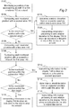
- Fig. 2 shows a method implemented in an aircraft docking system for guiding a pilot of an approaching aircraft 10 to a stop position 160 at a stand 20.
- the method will here, by way of example, be described with reference to the aircraft docking system 100 described hereinbelow. However, it is understood that the method is equally applicable for other aircraft docking systems within the scope of the appended claims.
- the position monitoring system 110 continuously monitors S102 a position of the approaching aircraft 10 within a volume 112 at the stand 20.
- the continuous monitoring may be initiated just prior to the aircraft 10 appearing within the monitored volume 112.
- the monitoring may be initiated as a result from the control unit 120 receiving information from the aircraft 10 and/or a control tower and/or an airport surveillance system that the aircraft 10 is about to approach the stand 20.
- the control unit 120 compares S104 said monitored position with the second area 150 (already defined and discussed hereinabove). If said monitored position is inside the second area 150, the control unit 120 determines S118 a lateral deviation from an expected position within said second area 150.
- the expected position may be defined by a predefined preferred transport path across the second area 150. Such preferred transport paths may be unique for each aircraft type and/or different lead-in lines of the stand 20. The preferred transport path may be aligned with a lead-in line.
- the control unit 120 then transmits S120 information pertaining to said relative deviation to the display 130 to show an indication to the pilot to adjust the course of the aircraft 10 during approach to the stand 20.
- the indication may comprise showing signs of directions, such as e.g. arrows on the display 130.
- the aircraft 10 has entered and passed across the second area 150, i.e. the outer area furthest away from the stop position 160.
- the aircraft 10 will then pass over the front boundary 142 of the first area 140 and enter inside the first area 140.
- the monitored position will then shift from being inside the second area 150 to being inside the first area 140.
- This shift will be picked up by the control unit 120 as it continuously compares S106 said monitored position with the first area 140.
- the control unit 120 further compares S108 the monitored position with the subsection 140a of the first area 140. If the monitored position is found to be inside the subsection 140a of the first area 140, the control unit 120 transmits S112 information to the display 130 to show an indication to the pilot of the approaching aircraft 10 to proceed with approaching the stand 20.
- control unit 120 determines S114, based on said comparison, a lateral deviation from an expected position within the subsection 140a and transmits S116 information pertaining to the relative deviation to the display 130 to show an indication to the pilot to adjust the course of the aircraft 10 during approach to the stand 20.
- the control unit 120 determines S114, based on said comparison, a lateral deviation from an expected position within the subsection 140a and transmits S116 information pertaining to the relative deviation to the display 130 to show an indication to the pilot to adjust the course of the aircraft 10 during approach to the stand 20.
- the control unit 120 transmits S110 information to the display 130 to show an indication to the pilot of the approaching aircraft 10 to stop the aircraft 10.
- the aircraft is deemed to be so far of course that safe docking will not be possible.
- the automatic docking procedure is hereby halted. In some cases, it is conceivable to reinstate automatic docking.
- the aircraft 10 may for example be towed backwards to a more promising starting position for approach, whereby the aircraft 10 is yet again allowed to approach the stand 20 guided by the aircraft docking system 100. In other cases, automatic docking will be abandoned and the docking will instead be carried out manually. The decision will depend on the situation.
- the extension of the first area 140 and/or the extension of the subsection 140a of the first area 140 may be determined based upon a number of different factors, such as e.g. dimensions of an aircraft expected to approach the stand, dimensions of the aircraft 10 approaching the stand, dimensions of the aircrafts at neighboring stands, an approach direction from which the aircraft 10 approaches the stand area, a lead-in line assigned to the approaching aircraft 10.
- the aircraft docking system 100 may obtain such information in advance from another entity at the airport, such as a control tower, an airport surveillance system, an airport operational database (AODB), the approaching aircraft 10 itself, other aircrafts etc.
- the extension of an area may be different for different aircraft types, different approach directions, different weather and so on.
- the system is thus powerful in the sense that it is capable of adjusting to the situation at hand.
- the extension of the first area 140 and/or the extension of the subsection 140a of the first area 140 can also be adjusted during an approach of the aircraft 10. This means that the definitions of the area boundaries may be adjusted during the process of docking. This may be necessary for example when another object moves within the stand area. Such an object may for example be a neighboring aircraft.
- Fig. 3 shows an example identical to the example shown in Fig. 1 with the exception that the extension of the subsection 240a of the first area 140 is different. As can be seen in Fig. 3 , the subsection 240a of the first area 140 has a varying lateral extension.
- the example embodiment shows a way of allowing a varying tolerance for misalignment across the first area 140. It is understood that the shape may be varied in different ways.
- Figure 4 shows an example embodiment where the stand 20' has two lead-in lines and hence at least two sets of first areas 340', 340" and subsections 340a', 340a" and second areas 350', 350".
- the scanned volume 112 is the same for the two different sets of areas. It is also conceivable that the scanned volume is shifted to the side so as to better receive the approaching aircraft.
- the main action taken by the control unit is to allow the display to show a message to the pilot to stop the aircraft.
- a further subsection of the first area may then be defined covering laterally distal portions of the first area.
- further actions may be taken in addition to show the stop indication, for example, sounding an alarm, signaling to ground crew, signaling to rescue units etc.
Landscapes
- Engineering & Computer Science (AREA)
- Physics & Mathematics (AREA)
- General Physics & Mathematics (AREA)
- Aviation & Aerospace Engineering (AREA)
- Electromagnetism (AREA)
- Radar, Positioning & Navigation (AREA)
- Remote Sensing (AREA)
- Computer Networks & Wireless Communication (AREA)
- Mechanical Engineering (AREA)
- Traffic Control Systems (AREA)
- Radar Systems Or Details Thereof (AREA)
Claims (13)
- Procédé mis en œuvre dans un système d'amarrage d'aéronef (100) pour guider un pilote d'un aéronef (10) en approche vers une position d'arrêt (160) à un stand (20), dans lequel le système d'amarrage d'aéronef (100) comprend un système de surveillance de position (110), une unité de commande (120), et un affichage (130), ledit procédé comprenant :le système de surveillance de position (110) surveillant (S102) une position de l'aéronef (10) en approche à l'intérieur d'un volume (112) au stand (20), dans lequel ledit volume a une extension longitudinale le long d'une direction d'approche (L) vers une position d'entrée prévue (115) de l'aéronef (10),l'unité de commande (120) comparant (S106) ladite position surveillée avec une première zone (140), ladite première zone (140) renfermant la position d'arrêt (160) et s'étendant le long de la direction d'approche (L) pour définir une frontière avant (142) faisant face à l'aéronef (10) en approche,l'unité de commande (120) comparant (S108) ladite position surveillée avec une sous-section (140a) de la première zone (140), ladite sous-section (140a) renfermant la position d'arrêt (160) et s'étendant le long de la direction d'approche (L) pour rencontrer une portion de la frontière avant (142) de la première zone (140), dans laquelle la sous-section (140a) partage une portion de ses frontières avec la première zone (140), ladite portion partagée étant une portion de la frontière avant (142) de la première zone (140),si ladite position surveillée se trouve être à l'intérieur de ladite sous-section (140a) de la première zone (140):
l'unité de commande (120) transmettant (S110) des informations à l'affichage (130) pour montrer une indication au pilote de l'aéronef (10) en approche de procéder à l'approche du stand (20),si ladite position surveillée se trouve à l'intérieur la première zone (140), mais pas à l'intérieur de ladite sous-section (140a) de la première zone (140):
l'unité de commande (120) transmettant (S112) des informations à l'affichage (130) pour montrer une indication au pilote de l'aéronef (10) en approche d'arrêter l'aéronef (10). - Procédé selon la revendication 1, comprenant en outre si ladite position surveillée se trouvant à l'intérieur de ladite sous-section (140a) de la première zone (140) :déterminer (S114), basé sur ladite comparaison, un écart latéral par rapport à une position prévue dans ladite sous-section (140a), etl'unité de commande (120) transmettant (S116) des informations concernant ledit écart relatif à l'affichage (130) pour montrer une indication au pilote d'ajuster la trajectoire de l'aéronef (10) lors de l'approche au stand (20).
- Procédé selon l'une quelconque des revendications 1 ou 2, dans lequel une ligne d'entrée (170) s'étend depuis la position d'arrêt (160) le long de la direction d'approche (L) pour fournir un guidage supplémentaire au pilote, et dans lequel ladite sous-section (140a) de la première zone (140) est définie de manière à englober la portion de la ligne d'entrée (170) étant à l'intérieur de la première zone (140).
- Procédé selon la revendication 3 lorsque dépendante de la revendication 2, dans lequel l'écart latérale est une distance latérale entre la position surveillée et la ligne d'entrée (170).
- Procédé selon l'une quelconque des revendications 1 à 4, comprenant en outre:l'unité de commande (120) comparant (S104) ladite position surveillée avec une seconde zone (150), ladite seconde zone (150) s'étendant vers l'extérieur depuis la frontière avant (142) de la première zone (140) pour définir une frontière avant (152) de la deuxième zone (150),si ladite position surveillée se trouve à l'intérieur de la deuxième zone (150): déterminer (S118), basé sur ladite comparaison, un écart latéral par rapport à une position prévue dans ladite deuxième zone (150), etl'unité de commande (120) transmettant (S120) des informations concernant ledit écart relatif à l'affichage (130) pour montrer une indication au pilote d'ajuster la trajectoire de l'aéronef (10) pendant l'approche au stand (20).
- Procédé selon l'une quelconque des revendications précédentes, dans lequel le système de surveillance de position (110) est un système de surveillance de position à laser adapté de manière à balayer en continu le volume (112) au stand (20), ledit volume (112) couvrant au moins la première zone (140).
- Procédé selon l'une quelconque des revendications précédentes, dans lequel ladite position surveillée concerne à la position du nez (12) de l'aéronef en approche (10).
- Procédé selon l'une quelconque des revendications précédentes, dans lequel l'extension de la première zone (140) et/ou l'extension de la sous-section (140a) de la première zone (140) est déterminée basée sur une ou plusieurs parmi la liste de: dimensions d'un aéronef devant s'approcher du stand, dimensions de l'aéronef (10) approchant du stand, dimensions des aéronefs aux stands voisins, une direction d'approche à partir de laquelle un aéronef s'approche de la zone du stand, et une ligne d'entrée assignée à l'aéronef en approche (10).
- Procédé selon la revendication 8, dans lequel la détermination de l'extension de la sous-section (140a) de la première zone (140) comprend la détermination d'une dimension latérale et/ou d'une dimension longitudinale de celle-ci, lesdites dimensions étant déterminées de telle sorte qu'un dégagement suffisant est fourni à l'aéronef en approche (10).
- Procédé selon l'une quelconque des revendications précédentes, dans lequel l'extension de la première zone (140) et/ou l'extension de la sous-section (140a) de la première zone (140) peut être ajustée pendant une approche de l'aéronef (10).
- Procédé selon la revendication 10, dans lequel ledit ajustement de l'extension ou des extensions est déterminé basé sur une ou plusieurs des : dimensions des aéronefs aux stands voisins, des positions des aéronefs aux stands voisins, et de la position surveillée de l'aéronef en approche (10).
- Support lisible par ordinateur comprenant des instructions de code informatique qui, lorsqu'elles sont exécutées par un dispositif ayant une capacité de traitement, sont adaptées de manière à exécuter le procédé selon l'une quelconque des revendications 1 à 10.
- Système d'amarrage d'aéronef (100) pour guider un pilote d'un aéronef en approche (10) vers une position d'arrêt (160) à un stand (20), le système d'amarrage d'aéronef (100) comprenant:un système de surveillance de position (110) agencé de manière à surveiller la position d'un aéronef en approche (10) à l'intérieur d'un volume (112) au poste (20), dans lequel ledit volume (112) à une extension longitudinale le long d'une direction d'approche (L) vers une position d'entrée prévue (115) de l'aéronef (10),un affichage (130) pour fournir des instructions au pilote de l'aéronef en approche (10), etune unité de commande (120) connectée fonctionnellement au système de surveillance de position (110) et à l'affichage (130), caractérisée en ce que le système d'amarrage d'aéronef (100) est configuré de manière à exécuter le procédé selon l'une quelconque des revendications 1 à 11.
Priority Applications (18)
| Application Number | Priority Date | Filing Date | Title |
|---|---|---|---|
| PT181782335T PT3584172T (pt) | 2018-06-18 | 2018-06-18 | Método e sistema para guiar um piloto de uma aeronave em aproximação para uma posição de paragem numa plataforma |
| PL18178233T PL3584172T3 (pl) | 2018-06-18 | 2018-06-18 | Sposób i układ prowadzenia pilota zbliżającego się statku powietrznego do pozycji zatrzymania na stanowisku |
| ES18178233T ES2841748T3 (es) | 2018-06-18 | 2018-06-18 | Un procedimiento y un sistema para guiar a un piloto de una aeronave que se aproxima a una posición de parada en un puesto de estacionamiento |
| DK18178233.5T DK3584172T3 (da) | 2018-06-18 | 2018-06-18 | Fremgangsmåde og system til at lede en pilot af et luftfartøj, der nærmer sig, til en stopposition ved en stand |
| EP18178233.5A EP3584172B1 (fr) | 2018-06-18 | 2018-06-18 | Procédé et système permettant de guider un pilote de l'approche d'un aéronef sur une position d'arrêt à un stand |
| TW108117147A TWI812717B (zh) | 2018-06-18 | 2019-05-17 | 用以引導抵達中飛行器飛行員至停機位的停止位置之方法及系統 |
| KR1020217000993A KR102299477B1 (ko) | 2018-06-18 | 2019-06-17 | 접근하는 항공기의 조종사를 주기장의 정지 위치로 안내하기 위한 방법 및 시스템 |
| BR112020023908A BR112020023908B8 (pt) | 2018-06-18 | 2019-06-17 | Método implementado em um sistema de docagem de aeronave, mídia legível por computador, e, sistema de docagem de aeronave para guiar um piloto |
| JP2020568743A JP6903828B1 (ja) | 2018-06-18 | 2019-06-17 | 駐機場の停止位置へ進入中の航空機のパイロットを誘導する方法およびシステム |
| CN201980034257.XA CN112166074B (zh) | 2018-06-18 | 2019-06-17 | 用于将驶近中航空器的飞行员引导到停机位处的停止位置的方法和系统 |
| MYPI2020006465A MY199300A (en) | 2018-06-18 | 2019-06-17 | A method and a system for guiding a pilot of an approaching aircraft to a stop position at a stand |
| SG11202011136QA SG11202011136QA (en) | 2018-06-18 | 2019-06-17 | A method and a system for guiding a pilot of an approaching aircraft to a stop position at a stand |
| PCT/EP2019/065796 WO2019243212A1 (fr) | 2018-06-18 | 2019-06-17 | Procédé et système de guidage d'un pilote d'un aéronef en approche vers une position d'arrêt au niveau d'un support |
| RU2020141981A RU2753006C1 (ru) | 2018-06-18 | 2019-06-17 | Способ и система информационной поддержки пилота заходящего на посадку воздушного судна |
| CA3101136A CA3101136C (fr) | 2018-06-18 | 2019-06-17 | Procede et systeme de guidage d'un pilote d'un aeronef en approche vers une position d'arret au niveau d'un support |
| AU2019289617A AU2019289617B2 (en) | 2018-06-18 | 2019-06-17 | A method and a system for guiding a pilot of an approaching aircraft to a stop position at a stand |
| US16/952,161 US11053023B2 (en) | 2018-06-18 | 2020-11-19 | Method and a system for guiding a pilot of an approaching aircraft to a stop position at a stand |
| ZA2020/07291A ZA202007291B (en) | 2018-06-18 | 2020-11-23 | A method and a system for guiding a pilot of an approaching aircraft to a stop position at a stand |
Applications Claiming Priority (1)
| Application Number | Priority Date | Filing Date | Title |
|---|---|---|---|
| EP18178233.5A EP3584172B1 (fr) | 2018-06-18 | 2018-06-18 | Procédé et système permettant de guider un pilote de l'approche d'un aéronef sur une position d'arrêt à un stand |
Publications (2)
| Publication Number | Publication Date |
|---|---|
| EP3584172A1 EP3584172A1 (fr) | 2019-12-25 |
| EP3584172B1 true EP3584172B1 (fr) | 2020-10-07 |
Family
ID=62748727
Family Applications (1)
| Application Number | Title | Priority Date | Filing Date |
|---|---|---|---|
| EP18178233.5A Active EP3584172B1 (fr) | 2018-06-18 | 2018-06-18 | Procédé et système permettant de guider un pilote de l'approche d'un aéronef sur une position d'arrêt à un stand |
Country Status (18)
| Country | Link |
|---|---|
| US (1) | US11053023B2 (fr) |
| EP (1) | EP3584172B1 (fr) |
| JP (1) | JP6903828B1 (fr) |
| KR (1) | KR102299477B1 (fr) |
| CN (1) | CN112166074B (fr) |
| AU (1) | AU2019289617B2 (fr) |
| BR (1) | BR112020023908B8 (fr) |
| CA (1) | CA3101136C (fr) |
| DK (1) | DK3584172T3 (fr) |
| ES (1) | ES2841748T3 (fr) |
| MY (1) | MY199300A (fr) |
| PL (1) | PL3584172T3 (fr) |
| PT (1) | PT3584172T (fr) |
| RU (1) | RU2753006C1 (fr) |
| SG (1) | SG11202011136QA (fr) |
| TW (1) | TWI812717B (fr) |
| WO (1) | WO2019243212A1 (fr) |
| ZA (1) | ZA202007291B (fr) |
Families Citing this family (9)
| Publication number | Priority date | Publication date | Assignee | Title |
|---|---|---|---|---|
| DK3757968T3 (da) * | 2019-06-28 | 2022-04-19 | Adb Safegate Sweden Ab | Lufthavnsstandpladsarrangement og fremgangsmåde |
| US11915603B2 (en) | 2020-06-16 | 2024-02-27 | Honeywell International Inc. | Docking guidance display methods and systems |
| EP3926608A3 (fr) * | 2020-06-16 | 2022-04-27 | Honeywell International Inc. | Procédés et systèmes d'affichage de guidage d'amarrage |
| US11975823B2 (en) | 2020-09-25 | 2024-05-07 | Borealis Technical Limited | Method for maneuvering an electric taxi drive system driven aircraft into an airport ramp parking location |
| KR102388289B1 (ko) * | 2021-04-01 | 2022-04-18 | 이화순 | 진입각 지시등을 구비한 항공기 진입감시장치 |
| EP4177864A1 (fr) * | 2021-11-09 | 2023-05-10 | TK Airport Solutions, S.A. | Système de guidage visuel d'amarrage |
| US20230267753A1 (en) * | 2022-02-24 | 2023-08-24 | Honeywell International Inc. | Learning based system and method for visual docking guidance to detect new approaching aircraft types |
| CN115690743B (zh) * | 2022-11-10 | 2025-12-16 | 青岛高重信息科技有限公司 | 一种基于深度学习的机场停机位入侵的检测方法 |
| CN119414753B (zh) * | 2024-10-29 | 2025-11-25 | 中国舰船研究设计中心 | 一种自动进出停机站位的牵引车控制方法及装置 |
Family Cites Families (24)
| Publication number | Priority date | Publication date | Assignee | Title |
|---|---|---|---|---|
| US4259658A (en) * | 1975-10-15 | 1981-03-31 | Basov Nikolai G | Aircraft carrier take-off and landing system and method for using same |
| US6324489B1 (en) * | 1999-10-29 | 2001-11-27 | Safegate International Ab | Aircraft identification and docking guidance systems |
| DE4406821A1 (de) | 1994-03-02 | 1995-09-07 | Hipp Johann | Vorrichtung zur Führung des Piloten eines sich seiner Parkposition nähernden Flugzeuges |
| WO1996012265A1 (fr) | 1994-10-14 | 1996-04-25 | Airport Technology In Scandinavia Ab | Systemes d'identification d'avion et de guidage pour garer un avion |
| RU2155384C2 (ru) * | 1994-10-14 | 2000-08-27 | Эрпорт Текнолоджи Ин Скандинавия Аб | Идентификация самолета и системы управления швартовкой |
| US5675661A (en) | 1995-10-12 | 1997-10-07 | Northrop Grumman Corporation | Aircraft docking system |
| FR2763727B1 (fr) * | 1997-05-20 | 1999-08-13 | Sagem | Procede et systeme de guidage d'un avion vers un poste d'accostage |
| US6563432B1 (en) | 2001-01-12 | 2003-05-13 | Safegate International Ab | Aircraft docking system and method with automatic checking of apron and detection of fog or snow |
| ES2223723T3 (es) | 2001-12-20 | 2005-03-01 | Safegate International Aktiebolag | Identificacion de linea central en un sistema de guiado de atraque. |
| US6914542B2 (en) * | 2002-11-13 | 2005-07-05 | Dew Engineering And Development Limited | Method and system for parking aircraft at an airport |
| SE529181C2 (sv) | 2005-10-04 | 2007-05-22 | Fmt Int Trade Ab | Förfarande för automatisk dockning av en passagerarbrygga eller en godshanteringsbrygga till en dörr hos ett flygplan |
| US7623044B2 (en) * | 2006-04-06 | 2009-11-24 | Honeywell International Inc. | Runway and taxiway turning guidance |
| US20080157947A1 (en) * | 2006-12-28 | 2008-07-03 | Neil Hutton | System and method for guiding an aircraft to a stopping position |
| US7702453B2 (en) * | 2007-03-23 | 2010-04-20 | Dew Engineering And Development Ulc | System and method for guiding an aircraft to a stopping position |
| SE536533C2 (sv) | 2012-04-30 | 2014-02-04 | Fmt Int Trade Ab | Förfarande för att identifiera ett flygplan i samband med parkering av flygplanet vid ett stand |
| SE536546C2 (sv) | 2012-04-30 | 2014-02-11 | Fmt Int Trade Ab | Förfarande jämte anordning för att identifiera ett flygplani samband med parkering av flygplanet vid ett stand |
| TWM484091U (zh) * | 2014-03-31 | 2014-08-11 | Unibase Information Corp | 具有稽核及影像同步功能的航空器導引系統、及其稽核與影像同步裝置 |
| CN105373135B (zh) * | 2014-08-01 | 2019-01-01 | 深圳中集天达空港设备有限公司 | 一种基于机器视觉的飞机入坞引导和机型识别的方法及系统 |
| RU2560220C1 (ru) * | 2014-09-04 | 2015-08-20 | Открытое акционерное общество "Концерн "Международные аэронавигационные системы" | Способ и устройство для управления наземным движением мобильных объектов на аэродроме |
| DE102014221751A1 (de) * | 2014-10-27 | 2016-04-28 | Robert Bosch Gmbh | Verfahren und Vorrichtung zum Führen eines Fahrzeugs auf einem Parkplatz |
| FR3038047B1 (fr) * | 2015-06-24 | 2019-08-09 | Dassault Aviation | Systeme d'affichage d'un aeronef, propre a afficher un marquage de localisation d'une zone de presence d'une rampe lumineuse d'approche et procede associe |
| KR101778623B1 (ko) | 2016-01-06 | 2017-09-27 | (주)안세기술 | 2d 레이저 센서와 모터를 구비하는 스캐너를 이용하여 항공기를 주기장에 안전하게 유도하는 방법 |
| ES2748042T3 (es) * | 2016-03-21 | 2020-03-12 | Adb Safegate Sweden Ab | Optimización del alcance de un sistema de atraque de aeronaves |
| CN106251711A (zh) * | 2016-08-24 | 2016-12-21 | 桂林信通科技有限公司 | 一种飞机泊位引导及距离显示信息系统 |
-
2018
- 2018-06-18 PT PT181782335T patent/PT3584172T/pt unknown
- 2018-06-18 PL PL18178233T patent/PL3584172T3/pl unknown
- 2018-06-18 ES ES18178233T patent/ES2841748T3/es active Active
- 2018-06-18 EP EP18178233.5A patent/EP3584172B1/fr active Active
- 2018-06-18 DK DK18178233.5T patent/DK3584172T3/da active
-
2019
- 2019-05-17 TW TW108117147A patent/TWI812717B/zh active
- 2019-06-17 BR BR112020023908A patent/BR112020023908B8/pt active IP Right Grant
- 2019-06-17 CA CA3101136A patent/CA3101136C/fr active Active
- 2019-06-17 SG SG11202011136QA patent/SG11202011136QA/en unknown
- 2019-06-17 RU RU2020141981A patent/RU2753006C1/ru active
- 2019-06-17 WO PCT/EP2019/065796 patent/WO2019243212A1/fr not_active Ceased
- 2019-06-17 CN CN201980034257.XA patent/CN112166074B/zh active Active
- 2019-06-17 KR KR1020217000993A patent/KR102299477B1/ko active Active
- 2019-06-17 MY MYPI2020006465A patent/MY199300A/en unknown
- 2019-06-17 AU AU2019289617A patent/AU2019289617B2/en active Active
- 2019-06-17 JP JP2020568743A patent/JP6903828B1/ja active Active
-
2020
- 2020-11-19 US US16/952,161 patent/US11053023B2/en active Active
- 2020-11-23 ZA ZA2020/07291A patent/ZA202007291B/en unknown
Non-Patent Citations (1)
| Title |
|---|
| None * |
Also Published As
| Publication number | Publication date |
|---|---|
| CN112166074A (zh) | 2021-01-01 |
| BR112020023908B8 (pt) | 2022-02-15 |
| US11053023B2 (en) | 2021-07-06 |
| EP3584172A1 (fr) | 2019-12-25 |
| DK3584172T3 (da) | 2020-11-30 |
| AU2019289617A1 (en) | 2020-12-03 |
| ES2841748T3 (es) | 2021-07-09 |
| KR102299477B1 (ko) | 2021-09-07 |
| TWI812717B (zh) | 2023-08-21 |
| WO2019243212A1 (fr) | 2019-12-26 |
| PT3584172T (pt) | 2021-01-08 |
| PL3584172T3 (pl) | 2021-05-04 |
| AU2019289617B2 (en) | 2021-01-21 |
| ZA202007291B (en) | 2022-04-28 |
| CA3101136A1 (fr) | 2019-12-26 |
| RU2753006C1 (ru) | 2021-08-11 |
| JP6903828B1 (ja) | 2021-07-14 |
| TW202001824A (zh) | 2020-01-01 |
| CN112166074B (zh) | 2021-07-09 |
| BR112020023908A2 (pt) | 2021-02-09 |
| KR20210013757A (ko) | 2021-02-05 |
| US20210070467A1 (en) | 2021-03-11 |
| CA3101136C (fr) | 2021-06-15 |
| SG11202011136QA (en) | 2020-12-30 |
| JP2021521059A (ja) | 2021-08-26 |
| BR112020023908B1 (pt) | 2021-07-27 |
| MY199300A (en) | 2023-10-24 |
Similar Documents
| Publication | Publication Date | Title |
|---|---|---|
| US11053023B2 (en) | Method and a system for guiding a pilot of an approaching aircraft to a stop position at a stand | |
| EP2660152B1 (fr) | Procédé d'identification d'un avion en connexion avec le stationnement de l'avion à une station | |
| US20250138183A1 (en) | Airport stand arrangement | |
| TR201815381T4 (tr) | Uçağın tanımlanması. | |
| KR102461008B1 (ko) | 공항 스탠드 장치 및 방법 | |
| HK40018679B (en) | A method and a system for guiding a pilot of an approaching aircraft to a stop position at a stand | |
| HK40018679A (en) | A method and a system for guiding a pilot of an approaching aircraft to a stop position at a stand | |
| WO2022268752A1 (fr) | Procédé de surveillance du mouvement vers l'arrière d'un aéronef au niveau d'un stand d'aéroport | |
| RU2778697C1 (ru) | Комплекс для места стоянки аэропорта и соответствующий способ | |
| HK40064691A (en) | An airport stand arrangement and method | |
| HK40064691B (en) | An airport stand arrangement and method | |
| HK40022221A (en) | Airport stand arrangement |
Legal Events
| Date | Code | Title | Description |
|---|---|---|---|
| STAA | Information on the status of an ep patent application or granted ep patent |
Free format text: STATUS: EXAMINATION IS IN PROGRESS |
|
| PUAI | Public reference made under article 153(3) epc to a published international application that has entered the european phase |
Free format text: ORIGINAL CODE: 0009012 |
|
| 17P | Request for examination filed |
Effective date: 20190328 |
|
| AK | Designated contracting states |
Kind code of ref document: A1 Designated state(s): AL AT BE BG CH CY CZ DE DK EE ES FI FR GB GR HR HU IE IS IT LI LT LU LV MC MK MT NL NO PL PT RO RS SE SI SK SM TR |
|
| AX | Request for extension of the european patent |
Extension state: BA ME |
|
| GRAP | Despatch of communication of intention to grant a patent |
Free format text: ORIGINAL CODE: EPIDOSNIGR1 |
|
| STAA | Information on the status of an ep patent application or granted ep patent |
Free format text: STATUS: GRANT OF PATENT IS INTENDED |
|
| INTG | Intention to grant announced |
Effective date: 20200326 |
|
| GRAJ | Information related to disapproval of communication of intention to grant by the applicant or resumption of examination proceedings by the epo deleted |
Free format text: ORIGINAL CODE: EPIDOSDIGR1 |
|
| STAA | Information on the status of an ep patent application or granted ep patent |
Free format text: STATUS: EXAMINATION IS IN PROGRESS |
|
| GRAP | Despatch of communication of intention to grant a patent |
Free format text: ORIGINAL CODE: EPIDOSNIGR1 |
|
| STAA | Information on the status of an ep patent application or granted ep patent |
Free format text: STATUS: GRANT OF PATENT IS INTENDED |
|
| INTC | Intention to grant announced (deleted) | ||
| GRAS | Grant fee paid |
Free format text: ORIGINAL CODE: EPIDOSNIGR3 |
|
| GRAA | (expected) grant |
Free format text: ORIGINAL CODE: 0009210 |
|
| STAA | Information on the status of an ep patent application or granted ep patent |
Free format text: STATUS: THE PATENT HAS BEEN GRANTED |
|
| INTG | Intention to grant announced |
Effective date: 20200812 |
|
| AK | Designated contracting states |
Kind code of ref document: B1 Designated state(s): AL AT BE BG CH CY CZ DE DK EE ES FI FR GB GR HR HU IE IS IT LI LT LU LV MC MK MT NL NO PL PT RO RS SE SI SK SM TR |
|
| REG | Reference to a national code |
Ref country code: GB Ref legal event code: FG4D |
|
| REG | Reference to a national code |
Ref country code: HK Ref legal event code: DE Ref document number: 40018679 Country of ref document: HK |
|
| REG | Reference to a national code |
Ref country code: CH Ref legal event code: EP Ref country code: AT Ref legal event code: REF Ref document number: 1320940 Country of ref document: AT Kind code of ref document: T Effective date: 20201015 |
|
| REG | Reference to a national code |
Ref country code: IE Ref legal event code: FG4D |
|
| REG | Reference to a national code |
Ref country code: DE Ref legal event code: R096 Ref document number: 602018008415 Country of ref document: DE |
|
| REG | Reference to a national code |
Ref country code: DK Ref legal event code: T3 Effective date: 20201124 |
|
| REG | Reference to a national code |
Ref country code: FI Ref legal event code: FGE |
|
| REG | Reference to a national code |
Ref country code: PT Ref legal event code: SC4A Ref document number: 3584172 Country of ref document: PT Date of ref document: 20210108 Kind code of ref document: T Free format text: AVAILABILITY OF NATIONAL TRANSLATION Effective date: 20210104 |
|
| REG | Reference to a national code |
Ref country code: NO Ref legal event code: T2 Effective date: 20201007 |
|
| REG | Reference to a national code |
Ref country code: NL Ref legal event code: FP |
|
| REG | Reference to a national code |
Ref country code: GR Ref legal event code: EP Ref document number: 20210400007 Country of ref document: GR Effective date: 20210215 |
|
| PG25 | Lapsed in a contracting state [announced via postgrant information from national office to epo] |
Ref country code: RS Free format text: LAPSE BECAUSE OF FAILURE TO SUBMIT A TRANSLATION OF THE DESCRIPTION OR TO PAY THE FEE WITHIN THE PRESCRIBED TIME-LIMIT Effective date: 20201007 |
|
| REG | Reference to a national code |
Ref country code: LT Ref legal event code: MG4D |
|
| PG25 | Lapsed in a contracting state [announced via postgrant information from national office to epo] |
Ref country code: LV Free format text: LAPSE BECAUSE OF FAILURE TO SUBMIT A TRANSLATION OF THE DESCRIPTION OR TO PAY THE FEE WITHIN THE PRESCRIBED TIME-LIMIT Effective date: 20201007 Ref country code: IS Free format text: LAPSE BECAUSE OF FAILURE TO SUBMIT A TRANSLATION OF THE DESCRIPTION OR TO PAY THE FEE WITHIN THE PRESCRIBED TIME-LIMIT Effective date: 20210207 Ref country code: BG Free format text: LAPSE BECAUSE OF FAILURE TO SUBMIT A TRANSLATION OF THE DESCRIPTION OR TO PAY THE FEE WITHIN THE PRESCRIBED TIME-LIMIT Effective date: 20210107 |
|
| PG25 | Lapsed in a contracting state [announced via postgrant information from national office to epo] |
Ref country code: HR Free format text: LAPSE BECAUSE OF FAILURE TO SUBMIT A TRANSLATION OF THE DESCRIPTION OR TO PAY THE FEE WITHIN THE PRESCRIBED TIME-LIMIT Effective date: 20201007 |
|
| REG | Reference to a national code |
Ref country code: DE Ref legal event code: R097 Ref document number: 602018008415 Country of ref document: DE |
|
| REG | Reference to a national code |
Ref country code: ES Ref legal event code: FG2A Ref document number: 2841748 Country of ref document: ES Kind code of ref document: T3 Effective date: 20210709 |
|
| REG | Reference to a national code |
Ref country code: AT Ref legal event code: UEP Ref document number: 1320940 Country of ref document: AT Kind code of ref document: T Effective date: 20201007 |
|
| PG25 | Lapsed in a contracting state [announced via postgrant information from national office to epo] |
Ref country code: RO Free format text: LAPSE BECAUSE OF FAILURE TO SUBMIT A TRANSLATION OF THE DESCRIPTION OR TO PAY THE FEE WITHIN THE PRESCRIBED TIME-LIMIT Effective date: 20201007 Ref country code: SK Free format text: LAPSE BECAUSE OF FAILURE TO SUBMIT A TRANSLATION OF THE DESCRIPTION OR TO PAY THE FEE WITHIN THE PRESCRIBED TIME-LIMIT Effective date: 20201007 Ref country code: LT Free format text: LAPSE BECAUSE OF FAILURE TO SUBMIT A TRANSLATION OF THE DESCRIPTION OR TO PAY THE FEE WITHIN THE PRESCRIBED TIME-LIMIT Effective date: 20201007 Ref country code: EE Free format text: LAPSE BECAUSE OF FAILURE TO SUBMIT A TRANSLATION OF THE DESCRIPTION OR TO PAY THE FEE WITHIN THE PRESCRIBED TIME-LIMIT Effective date: 20201007 Ref country code: SM Free format text: LAPSE BECAUSE OF FAILURE TO SUBMIT A TRANSLATION OF THE DESCRIPTION OR TO PAY THE FEE WITHIN THE PRESCRIBED TIME-LIMIT Effective date: 20201007 |
|
| PLBE | No opposition filed within time limit |
Free format text: ORIGINAL CODE: 0009261 |
|
| STAA | Information on the status of an ep patent application or granted ep patent |
Free format text: STATUS: NO OPPOSITION FILED WITHIN TIME LIMIT |
|
| 26N | No opposition filed |
Effective date: 20210708 |
|
| PG25 | Lapsed in a contracting state [announced via postgrant information from national office to epo] |
Ref country code: AL Free format text: LAPSE BECAUSE OF FAILURE TO SUBMIT A TRANSLATION OF THE DESCRIPTION OR TO PAY THE FEE WITHIN THE PRESCRIBED TIME-LIMIT Effective date: 20201007 |
|
| PG25 | Lapsed in a contracting state [announced via postgrant information from national office to epo] |
Ref country code: SI Free format text: LAPSE BECAUSE OF FAILURE TO SUBMIT A TRANSLATION OF THE DESCRIPTION OR TO PAY THE FEE WITHIN THE PRESCRIBED TIME-LIMIT Effective date: 20201007 |
|
| PG25 | Lapsed in a contracting state [announced via postgrant information from national office to epo] |
Ref country code: MC Free format text: LAPSE BECAUSE OF FAILURE TO SUBMIT A TRANSLATION OF THE DESCRIPTION OR TO PAY THE FEE WITHIN THE PRESCRIBED TIME-LIMIT Effective date: 20201007 |
|
| PG25 | Lapsed in a contracting state [announced via postgrant information from national office to epo] |
Ref country code: LU Free format text: LAPSE BECAUSE OF NON-PAYMENT OF DUE FEES Effective date: 20210618 |
|
| PG25 | Lapsed in a contracting state [announced via postgrant information from national office to epo] |
Ref country code: IS Free format text: LAPSE BECAUSE OF FAILURE TO SUBMIT A TRANSLATION OF THE DESCRIPTION OR TO PAY THE FEE WITHIN THE PRESCRIBED TIME-LIMIT Effective date: 20210207 |
|
| P01 | Opt-out of the competence of the unified patent court (upc) registered |
Effective date: 20230512 |
|
| PG25 | Lapsed in a contracting state [announced via postgrant information from national office to epo] |
Ref country code: CY Free format text: LAPSE BECAUSE OF FAILURE TO SUBMIT A TRANSLATION OF THE DESCRIPTION OR TO PAY THE FEE WITHIN THE PRESCRIBED TIME-LIMIT Effective date: 20201007 |
|
| PG25 | Lapsed in a contracting state [announced via postgrant information from national office to epo] |
Ref country code: HU Free format text: LAPSE BECAUSE OF FAILURE TO SUBMIT A TRANSLATION OF THE DESCRIPTION OR TO PAY THE FEE WITHIN THE PRESCRIBED TIME-LIMIT; INVALID AB INITIO Effective date: 20180618 |
|
| PG25 | Lapsed in a contracting state [announced via postgrant information from national office to epo] |
Ref country code: MK Free format text: LAPSE BECAUSE OF FAILURE TO SUBMIT A TRANSLATION OF THE DESCRIPTION OR TO PAY THE FEE WITHIN THE PRESCRIBED TIME-LIMIT Effective date: 20201007 |
|
| PG25 | Lapsed in a contracting state [announced via postgrant information from national office to epo] |
Ref country code: MT Free format text: LAPSE BECAUSE OF FAILURE TO SUBMIT A TRANSLATION OF THE DESCRIPTION OR TO PAY THE FEE WITHIN THE PRESCRIBED TIME-LIMIT Effective date: 20201007 |
|
| PGFP | Annual fee paid to national office [announced via postgrant information from national office to epo] |
Ref country code: NL Payment date: 20250520 Year of fee payment: 8 |
|
| PGFP | Annual fee paid to national office [announced via postgrant information from national office to epo] |
Ref country code: FI Payment date: 20250520 Year of fee payment: 8 |
|
| PGFP | Annual fee paid to national office [announced via postgrant information from national office to epo] |
Ref country code: PL Payment date: 20250522 Year of fee payment: 8 Ref country code: DE Payment date: 20250520 Year of fee payment: 8 |
|
| PGFP | Annual fee paid to national office [announced via postgrant information from national office to epo] |
Ref country code: DK Payment date: 20250520 Year of fee payment: 8 Ref country code: GB Payment date: 20250520 Year of fee payment: 8 |
|
| PGFP | Annual fee paid to national office [announced via postgrant information from national office to epo] |
Ref country code: NO Payment date: 20250522 Year of fee payment: 8 |
|
| PGFP | Annual fee paid to national office [announced via postgrant information from national office to epo] |
Ref country code: IT Payment date: 20250520 Year of fee payment: 8 Ref country code: BE Payment date: 20250520 Year of fee payment: 8 |
|
| PGFP | Annual fee paid to national office [announced via postgrant information from national office to epo] |
Ref country code: PT Payment date: 20250521 Year of fee payment: 8 |
|
| PGFP | Annual fee paid to national office [announced via postgrant information from national office to epo] |
Ref country code: FR Payment date: 20250520 Year of fee payment: 8 |
|
| PGFP | Annual fee paid to national office [announced via postgrant information from national office to epo] |
Ref country code: GR Payment date: 20250522 Year of fee payment: 8 |
|
| PGFP | Annual fee paid to national office [announced via postgrant information from national office to epo] |
Ref country code: AT Payment date: 20250522 Year of fee payment: 8 |
|
| PGFP | Annual fee paid to national office [announced via postgrant information from national office to epo] |
Ref country code: TR Payment date: 20250526 Year of fee payment: 8 |
|
| PGFP | Annual fee paid to national office [announced via postgrant information from national office to epo] |
Ref country code: CZ Payment date: 20250529 Year of fee payment: 8 |
|
| PGFP | Annual fee paid to national office [announced via postgrant information from national office to epo] |
Ref country code: IE Payment date: 20250522 Year of fee payment: 8 |
|
| PGFP | Annual fee paid to national office [announced via postgrant information from national office to epo] |
Ref country code: SE Payment date: 20250520 Year of fee payment: 8 |
|
| PGFP | Annual fee paid to national office [announced via postgrant information from national office to epo] |
Ref country code: ES Payment date: 20250701 Year of fee payment: 8 |
|
| PGFP | Annual fee paid to national office [announced via postgrant information from national office to epo] |
Ref country code: CH Payment date: 20250701 Year of fee payment: 8 |