EP3584232A1 - Procédé de soudage par chauffage par induction pour verre sous vide - Google Patents
Procédé de soudage par chauffage par induction pour verre sous vide Download PDFInfo
- Publication number
- EP3584232A1 EP3584232A1 EP18792086.3A EP18792086A EP3584232A1 EP 3584232 A1 EP3584232 A1 EP 3584232A1 EP 18792086 A EP18792086 A EP 18792086A EP 3584232 A1 EP3584232 A1 EP 3584232A1
- Authority
- EP
- European Patent Office
- Prior art keywords
- metal layer
- glass substrate
- center
- frequency induction
- welding head
- Prior art date
- Legal status (The legal status is an assumption and is not a legal conclusion. Google has not performed a legal analysis and makes no representation as to the accuracy of the status listed.)
- Withdrawn
Links
Images


Classifications
-
- C—CHEMISTRY; METALLURGY
- C03—GLASS; MINERAL OR SLAG WOOL
- C03C—CHEMICAL COMPOSITION OF GLASSES, GLAZES OR VITREOUS ENAMELS; SURFACE TREATMENT OF GLASS; SURFACE TREATMENT OF FIBRES OR FILAMENTS MADE FROM GLASS, MINERALS OR SLAGS; JOINING GLASS TO GLASS OR OTHER MATERIALS
- C03C27/00—Joining pieces of glass to pieces of other inorganic material; Joining glass to glass other than by fusing
- C03C27/06—Joining glass to glass by processes other than fusing
- C03C27/10—Joining glass to glass by processes other than fusing with the aid of adhesive specially adapted for that purpose
-
- B—PERFORMING OPERATIONS; TRANSPORTING
- B23—MACHINE TOOLS; METAL-WORKING NOT OTHERWISE PROVIDED FOR
- B23K—SOLDERING OR UNSOLDERING; WELDING; CLADDING OR PLATING BY SOLDERING OR WELDING; CUTTING BY APPLYING HEAT LOCALLY, e.g. FLAME CUTTING; WORKING BY LASER BEAM
- B23K1/00—Soldering, e.g. brazing, or unsoldering
- B23K1/0008—Soldering, e.g. brazing, or unsoldering specially adapted for particular articles or work
-
- C—CHEMISTRY; METALLURGY
- C03—GLASS; MINERAL OR SLAG WOOL
- C03C—CHEMICAL COMPOSITION OF GLASSES, GLAZES OR VITREOUS ENAMELS; SURFACE TREATMENT OF GLASS; SURFACE TREATMENT OF FIBRES OR FILAMENTS MADE FROM GLASS, MINERALS OR SLAGS; JOINING GLASS TO GLASS OR OTHER MATERIALS
- C03C27/00—Joining pieces of glass to pieces of other inorganic material; Joining glass to glass other than by fusing
- C03C27/06—Joining glass to glass by processes other than fusing
- C03C27/08—Joining glass to glass by processes other than fusing with the aid of intervening metal
-
- B—PERFORMING OPERATIONS; TRANSPORTING
- B23—MACHINE TOOLS; METAL-WORKING NOT OTHERWISE PROVIDED FOR
- B23K—SOLDERING OR UNSOLDERING; WELDING; CLADDING OR PLATING BY SOLDERING OR WELDING; CUTTING BY APPLYING HEAT LOCALLY, e.g. FLAME CUTTING; WORKING BY LASER BEAM
- B23K1/00—Soldering, e.g. brazing, or unsoldering
- B23K1/002—Soldering by means of induction heating
-
- B—PERFORMING OPERATIONS; TRANSPORTING
- B23—MACHINE TOOLS; METAL-WORKING NOT OTHERWISE PROVIDED FOR
- B23K—SOLDERING OR UNSOLDERING; WELDING; CLADDING OR PLATING BY SOLDERING OR WELDING; CUTTING BY APPLYING HEAT LOCALLY, e.g. FLAME CUTTING; WORKING BY LASER BEAM
- B23K1/00—Soldering, e.g. brazing, or unsoldering
- B23K1/19—Soldering, e.g. brazing, or unsoldering taking account of the properties of the materials to be soldered
-
- C—CHEMISTRY; METALLURGY
- C03—GLASS; MINERAL OR SLAG WOOL
- C03B—MANUFACTURE, SHAPING, OR SUPPLEMENTARY PROCESSES
- C03B23/00—Re-forming shaped glass
- C03B23/20—Uniting glass pieces by fusing without substantial reshaping
- C03B23/24—Making hollow glass sheets or bricks
-
- C—CHEMISTRY; METALLURGY
- C03—GLASS; MINERAL OR SLAG WOOL
- C03B—MANUFACTURE, SHAPING, OR SUPPLEMENTARY PROCESSES
- C03B23/00—Re-forming shaped glass
- C03B23/20—Uniting glass pieces by fusing without substantial reshaping
- C03B23/24—Making hollow glass sheets or bricks
- C03B23/245—Hollow glass sheets
-
- E—FIXED CONSTRUCTIONS
- E06—DOORS, WINDOWS, SHUTTERS, OR ROLLER BLINDS IN GENERAL; LADDERS
- E06B—FIXED OR MOVABLE CLOSURES FOR OPENINGS IN BUILDINGS, VEHICLES, FENCES OR LIKE ENCLOSURES IN GENERAL, e.g. DOORS, WINDOWS, BLINDS, GATES
- E06B3/00—Window sashes, door leaves, or like elements for closing wall or like openings; Layout of fixed or moving closures, e.g. windows in wall or like openings; Features of rigidly-mounted outer frames relating to the mounting of wing frames
- E06B3/66—Units comprising two or more parallel glass or like panes permanently secured together
- E06B3/6612—Evacuated glazing units
-
- E—FIXED CONSTRUCTIONS
- E06—DOORS, WINDOWS, SHUTTERS, OR ROLLER BLINDS IN GENERAL; LADDERS
- E06B—FIXED OR MOVABLE CLOSURES FOR OPENINGS IN BUILDINGS, VEHICLES, FENCES OR LIKE ENCLOSURES IN GENERAL, e.g. DOORS, WINDOWS, BLINDS, GATES
- E06B3/00—Window sashes, door leaves, or like elements for closing wall or like openings; Layout of fixed or moving closures, e.g. windows in wall or like openings; Features of rigidly-mounted outer frames relating to the mounting of wing frames
- E06B3/66—Units comprising two or more parallel glass or like panes permanently secured together
- E06B3/663—Elements for spacing panes
- E06B3/66309—Section members positioned at the edges of the glazing unit
- E06B3/66342—Section members positioned at the edges of the glazing unit characterised by their sealed connection to the panes
- E06B3/66357—Soldered connections or the like
-
- E—FIXED CONSTRUCTIONS
- E06—DOORS, WINDOWS, SHUTTERS, OR ROLLER BLINDS IN GENERAL; LADDERS
- E06B—FIXED OR MOVABLE CLOSURES FOR OPENINGS IN BUILDINGS, VEHICLES, FENCES OR LIKE ENCLOSURES IN GENERAL, e.g. DOORS, WINDOWS, BLINDS, GATES
- E06B3/00—Window sashes, door leaves, or like elements for closing wall or like openings; Layout of fixed or moving closures, e.g. windows in wall or like openings; Features of rigidly-mounted outer frames relating to the mounting of wing frames
- E06B3/66—Units comprising two or more parallel glass or like panes permanently secured together
- E06B3/673—Assembling the units
- E06B3/67326—Assembling spacer elements with the panes
- E06B3/67334—Assembling spacer elements with the panes by soldering; Preparing the panes therefor
-
- B—PERFORMING OPERATIONS; TRANSPORTING
- B23—MACHINE TOOLS; METAL-WORKING NOT OTHERWISE PROVIDED FOR
- B23K—SOLDERING OR UNSOLDERING; WELDING; CLADDING OR PLATING BY SOLDERING OR WELDING; CUTTING BY APPLYING HEAT LOCALLY, e.g. FLAME CUTTING; WORKING BY LASER BEAM
- B23K2103/00—Materials to be soldered, welded or cut
- B23K2103/50—Inorganic materials other than metals or composite materials
- B23K2103/54—Glass
-
- E—FIXED CONSTRUCTIONS
- E06—DOORS, WINDOWS, SHUTTERS, OR ROLLER BLINDS IN GENERAL; LADDERS
- E06B—FIXED OR MOVABLE CLOSURES FOR OPENINGS IN BUILDINGS, VEHICLES, FENCES OR LIKE ENCLOSURES IN GENERAL, e.g. DOORS, WINDOWS, BLINDS, GATES
- E06B3/00—Window sashes, door leaves, or like elements for closing wall or like openings; Layout of fixed or moving closures, e.g. windows in wall or like openings; Features of rigidly-mounted outer frames relating to the mounting of wing frames
- E06B3/66—Units comprising two or more parallel glass or like panes permanently secured together
- E06B3/663—Elements for spacing panes
- E06B3/66309—Section members positioned at the edges of the glazing unit
- E06B3/66333—Section members positioned at the edges of the glazing unit of unusual substances, e.g. wood or other fibrous materials, glass or other transparent materials
- E06B2003/66338—Section members positioned at the edges of the glazing unit of unusual substances, e.g. wood or other fibrous materials, glass or other transparent materials of glass
-
- Y—GENERAL TAGGING OF NEW TECHNOLOGICAL DEVELOPMENTS; GENERAL TAGGING OF CROSS-SECTIONAL TECHNOLOGIES SPANNING OVER SEVERAL SECTIONS OF THE IPC; TECHNICAL SUBJECTS COVERED BY FORMER USPC CROSS-REFERENCE ART COLLECTIONS [XRACs] AND DIGESTS
- Y02—TECHNOLOGIES OR APPLICATIONS FOR MITIGATION OR ADAPTATION AGAINST CLIMATE CHANGE
- Y02A—TECHNOLOGIES FOR ADAPTATION TO CLIMATE CHANGE
- Y02A30/00—Adapting or protecting infrastructure or their operation
- Y02A30/24—Structural elements or technologies for improving thermal insulation
- Y02A30/249—Glazing, e.g. vacuum glazing
-
- Y—GENERAL TAGGING OF NEW TECHNOLOGICAL DEVELOPMENTS; GENERAL TAGGING OF CROSS-SECTIONAL TECHNOLOGIES SPANNING OVER SEVERAL SECTIONS OF THE IPC; TECHNICAL SUBJECTS COVERED BY FORMER USPC CROSS-REFERENCE ART COLLECTIONS [XRACs] AND DIGESTS
- Y02—TECHNOLOGIES OR APPLICATIONS FOR MITIGATION OR ADAPTATION AGAINST CLIMATE CHANGE
- Y02B—CLIMATE CHANGE MITIGATION TECHNOLOGIES RELATED TO BUILDINGS, e.g. HOUSING, HOUSE APPLIANCES OR RELATED END-USER APPLICATIONS
- Y02B80/00—Architectural or constructional elements improving the thermal performance of buildings
- Y02B80/22—Glazing, e.g. vaccum glazing
Definitions
- the present invention relates to the technical field of vacuum insulated glass, and in particular to an induction-heating welding method for vacuum insulated glass.
- vacuum insulated glass is an emerging category of glass, and is generally composed of two pieces of glass between which is a vacuum layer. Due to the existence of this vacuum layer, vacuum insulated glass has good performance in sound insulation, heat insulation and condensation resistance, and is more in line with the national development requirements for energy conservation and environmental protection.
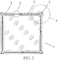
- the high-frequency induction welding head Since the solder and the metal layer coexist in the sealing region, in addition to heating the solder, the high-frequency induction welding head also heats the metal layer in the sealing region during the operation. In the actual production process, it is found that the glass substrate often has a phenomenon of over-burning of the metal layer in its corner position, referring to the position of the high-frequency induction welding head in FIG. 2 for the corner position, so that the bonding strength between the metal layer and the glass substrate is greatly reduced.
- the inventors have found through research that in theory, the above problem can be solved by reducing the power of induction heating, increasing the moving speed of the high-frequency induction welding head and changing the height between the high-frequency induction welding head and the metal layer.
- the above-mentioned means had low operability, and had certain, but not obvious effects.
- the present invention aims to provide an induction-heating welding method for vacuum insulated glass.
- the position of a moving trajectory of the center of the high-frequency induction welding head relative to the center line of the width direction of the metal layer is changed, so that the moving trajectory of the center of the high-frequency induction welding head deviates from the center line of the width direction of the metal layers, and thus, induction power of the metal layers in the corner regions is reduced, thereby avoiding the over-burning phenomenon of the metal layers in the corner regions.
- the corner region is explained as follows: the region where the metal layer is redirected at the center line of the width direction is the corner region.
- the present invention adopts the following technical solution: An induction-heating welding method for vacuum insulated glass is provided.
- the vacuum insulated glass comprises an upper glass substrate and a lower glass substrate.
- Metal layers are prepared in regions to be sealed of the upper glass substrate and the lower glass substrate.
- a continuous solder is distributed on the metal layer in the region to be sealed of the lower glass substrate.
- the upper glass substrate and the lower glass substrate are superposed.
- the center of a high-frequency induction welding head moves forward along the center line of the width direction of the metal layers; during induction heating of corner regions of the metal layers, the position of a moving trajectory of the center of the high-frequency induction welding head relative to the center line of the width direction of the metal layer is changed, so that the moving trajectory of the center of the high-frequency induction welding head deviates from the center line of the width direction of the metal layers, and thus, induction power of the metal layers in the corner regions is reduced, and overheating of the metal layers in the corner regions is avoided.
- the manner of changing the position of a moving trajectory of the center of the high-frequency induction welding head relative to the center line of the width direction of the metal layer is that the moving trajectory of the center of the high-frequency induction welding head in the corner region is located outside the center line of the width direction of the metal layer.
- the manner of changing the position of a moving trajectory of the center of the high-frequency induction welding head relative to the center line of the width direction of the metal layer is that a shape of the metal layer is changed such that the inner edge and the outer edge of the metal layer in the corner region are both arc-shaped.
- an arc radius of the inner edge of the metal layer in the corner region is r
- an arc radius of the outer edge of the metal layer in the corner region is R
- a width of a straight segment of the metal layer is d
- d R-r.
- the metal layer disposed in the region to be sealed of the glass substrate is in a shape of a circular ring, a width of the circular ring is d, a radius of the inner circle of the circular ring is r, the moving trajectory of the center of the high-frequency induction welding head is a circle concentric with the circular ring, a radius of the circle is R, and r+d/2 ⁇ R ⁇ r+d.
- the position of the moving trajectory of the center of the high-frequency induction welding head relative to the center line of the width direction of the metal layer is changed, so that a distance of the moving trajectory of the center of the high-frequency induction welding head deviating from the center line of the width direction of the metal layer is less than half of the width of the metal layer.
- the position of the moving trajectory of the center of the high-frequency induction welding head relative to the center line of the width direction of the metal layer is changed, so that the moving trajectory of the center of the high-frequency induction welding head deviates from the center line of the width direction of the metal layers, and thus, induction power of the metal layers in the corner regions is reduced, thereby avoiding the over-burning of the metal layers.
- the vacuum insulated glass obtained by the method the sealing performance of the sealing region is improved, the qualification rate of the product is increased, and the service life of the vacuum insulated glass is prolonged.
- 1 glass substrate 2 metal layer, 21 outer edge of metal layer in corner region, 22 inner edge of metal layer in corner region, 23 center line of width direction of metal layer, 3 high-frequency induction welding head, 4 moving route.
- spatially relative terms such as “above”, “below”, “left”, and “right” may be used herein to describe a relationship between one element or feature shown in the figure and another element or feature. It should be understood that such spatially relative terms are intended to encompass different orientations of the device in addition to the orientation depicted in the figures. For example, if the device in the figure is turned over, an element or feature described as being “below” another element or feature will then be “above” the other element or feature. Therefore, the exemplary term “below” may encompasses both the above and below orientations.
- the device may also be oriented in other ways (for example, rotated 90 degrees or at other orientations), and the spatially relative terms used herein are to be interpreted accordingly.
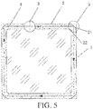
- FIG. 5 shows a second specific implementation of the induction-heating welding method for vacuum insulated glass according to the present invention.
- the glass substrate 1 to be sealed is glass having a square surface
- a metal layer 2 is previously disposed in the sealing region around the glass substrate 1
- a continuous solder is distributed on the metal layer 2.
- the high-frequency induction welding head 3 moves forward at a uniform speed while the center of the high-frequency induction welding head 3 is aligned with the center line of the width direction of the metal layer 2, and the moving route 4 thereof is a straight line.
- the moving route of the high-frequency induction welding head 3 is kept unchanged, with reference to FIG.
- the outer edge 21 and the inner edge 22 of the metal layer in the corner region are arc-shaped, so that the center of the high-frequency induction welding head 3 deviates outwardly from the center line of the metal layer 2 in the moving process, and thus, induction power of the metal layer 2 in the corner region is reduced.
- the deviation distance should be less than half of the width of the metal layer 2.
- the width of the metal layer is preferably 8 mm, the arc radius of the inner edge of the metal layer in the corner region is preferably 3 mm, and the arc radius of the outer edge of the metal layer in the corner region is preferably 11 mm.
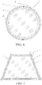
- FIG. 6 shows a third specific implementation of the induction-heating welding method for vacuum insulated glass according to the present invention.
- the surface of the glass substrate 1 to be sealed is in the shape of a circle
- a metal layer 2 in the shape of a circular ring is previously disposed in the sealing region around the glass substrate 1
- the width of the circular ring is d
- the radius of the inner circle of the circular ring is r.
- the metal layer 2 in this embodiment is all the corner region with no straight segments.
- the welding method for the corner region is substantially the same as that described in Embodiment 1.
- FIG. 7 shows a fourth specific implementation of the induction-heating welding method for vacuum insulated glass according to the present invention.
- the welding manner is substantially the same as in Embodiment 1, except that the surface of the glass substrate 1 in this embodiment is in the shape of a trapezoid.
- FIG. 8 shows a fifth specific implementation of the induction-heating welding method for vacuum insulated glass according to the present invention.
- the welding manner is substantially the same as in Embodiment 1, except that the surface of the glass substrate 1 in this embodiment is in the shape of a triangle.
Landscapes
- Engineering & Computer Science (AREA)
- Chemical & Material Sciences (AREA)
- Materials Engineering (AREA)
- Mechanical Engineering (AREA)
- Structural Engineering (AREA)
- Civil Engineering (AREA)
- Organic Chemistry (AREA)
- Ceramic Engineering (AREA)
- Geochemistry & Mineralogy (AREA)
- General Chemical & Material Sciences (AREA)
- Chemical Kinetics & Catalysis (AREA)
- Life Sciences & Earth Sciences (AREA)
- Joining Of Glass To Other Materials (AREA)
- Securing Of Glass Panes Or The Like (AREA)
- Manufacture Of Electron Tubes, Discharge Lamp Vessels, Lead-In Wires, And The Like (AREA)
Applications Claiming Priority (2)
| Application Number | Priority Date | Filing Date | Title |
|---|---|---|---|
| CN201710282659 | 2017-04-26 | ||
| PCT/CN2018/081812 WO2018196570A1 (fr) | 2017-04-26 | 2018-04-04 | Procédé de soudage par chauffage par induction pour verre sous vide |
Publications (2)
| Publication Number | Publication Date |
|---|---|
| EP3584232A1 true EP3584232A1 (fr) | 2019-12-25 |
| EP3584232A4 EP3584232A4 (fr) | 2020-04-08 |
Family
ID=60430289
Family Applications (2)
| Application Number | Title | Priority Date | Filing Date |
|---|---|---|---|
| EP17908035.3A Active EP3584231B1 (fr) | 2017-04-26 | 2017-11-10 | Produit en verre sous vide |
| EP18792086.3A Withdrawn EP3584232A4 (fr) | 2017-04-26 | 2018-04-04 | Procédé de soudage par chauffage par induction pour verre sous vide |
Family Applications Before (1)
| Application Number | Title | Priority Date | Filing Date |
|---|---|---|---|
| EP17908035.3A Active EP3584231B1 (fr) | 2017-04-26 | 2017-11-10 | Produit en verre sous vide |
Country Status (9)
| Country | Link |
|---|---|
| US (2) | US11459814B2 (fr) |
| EP (2) | EP3584231B1 (fr) |
| JP (2) | JP7023982B2 (fr) |
| KR (2) | KR102360064B1 (fr) |
| CN (2) | CN107417140B (fr) |
| AU (2) | AU2017412184B2 (fr) |
| CA (2) | CA3056172C (fr) |
| RU (2) | RU2736249C1 (fr) |
| WO (2) | WO2018196334A1 (fr) |
Families Citing this family (7)
| Publication number | Priority date | Publication date | Assignee | Title |
|---|---|---|---|---|
| CN107417140B (zh) | 2017-04-26 | 2020-01-14 | 洛阳兰迪玻璃机器股份有限公司 | 一种真空玻璃的感应加热焊接方法 |
| CN109494196B (zh) * | 2018-12-21 | 2021-01-01 | 西安赛尔电子材料科技有限公司 | 一种高硅铝合金封装外壳及其制作方法 |
| CN114735952A (zh) * | 2021-01-08 | 2022-07-12 | 洛阳兰迪玻璃机器股份有限公司 | 真空玻璃封接方法及真空玻璃、真空玻璃封接用焊料带 |
| CN115703166A (zh) * | 2021-08-04 | 2023-02-17 | 大族激光科技产业集团股份有限公司 | 一种半导体激光焊接oled的方法及激光焊接设备 |
| CN114541933A (zh) * | 2022-04-08 | 2022-05-27 | 四川零零昊科技有限公司 | 一种真空玻璃的封边结构及其封边方法 |
| CN115745429A (zh) * | 2022-11-23 | 2023-03-07 | 四川零零昊科技有限公司 | 真空玻璃在线封口系统、在线封口方法和连续生产系统 |
| US12442244B2 (en) * | 2022-11-23 | 2025-10-14 | LuxWall, Inc. | Vacuum insulated panel seal density |
Family Cites Families (28)
| Publication number | Priority date | Publication date | Assignee | Title |
|---|---|---|---|---|
| US2235680A (en) * | 1937-07-14 | 1941-03-18 | Libbey Owens Ford Glass Co | Multiple glass sheet glazing unit and method of making the same |
| US2624979A (en) * | 1950-03-14 | 1953-01-13 | Pittsburgh Corning Corp | Method of producing welded double glazed units |
| JP3237544B2 (ja) | 1996-10-11 | 2001-12-10 | 富士通株式会社 | 平面表示パネルの製造方法及び平面表示パネル |
| JPH11268934A (ja) * | 1998-03-24 | 1999-10-05 | Asahi Glass Co Ltd | 真空複層ガラスの製造方法 |
| CN100482605C (zh) * | 2004-09-08 | 2009-04-29 | 淮安市淮阴辉煌真空镀膜有限公司 | 制造层板真空玻璃的新方法 |
| US7371143B2 (en) * | 2004-10-20 | 2008-05-13 | Corning Incorporated | Optimization of parameters for sealing organic emitting light diode (OLED) displays |
| DE102007029031A1 (de) * | 2007-06-23 | 2008-12-24 | Fraunhofer-Gesellschaft zur Förderung der angewandten Forschung e.V. | Verfahren zum dauerhaften Verbinden zweier Komponenten durch Löten mit Glas- oder Metalllot |
| CN101215076B (zh) * | 2008-01-07 | 2012-07-04 | 左树森 | 一种真空玻璃的制备方法 |
| KR20100110544A (ko) * | 2009-04-03 | 2010-10-13 | 김현승 | 고주파 유도가열을 이용한 전기히터 |
| JP2011011925A (ja) * | 2009-06-30 | 2011-01-20 | Asahi Glass Co Ltd | 封着材料層付きガラス部材とそれを用いた電子デバイスおよびその製造方法 |
| CN102079619B (zh) * | 2009-11-27 | 2012-02-15 | 洛阳兰迪玻璃机器股份有限公司 | 一种玻璃板复合封接方法 |
| CN102079632A (zh) * | 2009-11-27 | 2011-06-01 | 洛阳兰迪玻璃机器有限公司 | 一种真空玻璃封接方法及真空玻璃产品 |
| CN102020415B (zh) * | 2010-03-02 | 2014-06-04 | 青岛亨达玻璃科技有限公司 | 弧形真空玻璃 |
| JP2012041196A (ja) * | 2010-08-12 | 2012-03-01 | Asahi Glass Co Ltd | 封着材料層付きガラス部材とそれを用いた電子デバイスおよびその製造方法 |
| CN102452801B (zh) * | 2010-10-29 | 2016-05-25 | 洛阳兰迪玻璃机器股份有限公司 | 一种真空玻璃封接方法及其产品 |
| CN102476926B (zh) * | 2010-11-23 | 2013-12-18 | 洛阳兰迪玻璃机器股份有限公司 | 一种真空玻璃封接装置 |
| WO2012075724A1 (fr) * | 2010-12-10 | 2012-06-14 | Luoyang Landglass Technology Co., Ltd. | Composant de verre à vide |
| TWI636875B (zh) * | 2013-02-04 | 2018-10-01 | Semiconductor Energy Laboratory Co., Ltd. | 玻璃層的形成方法及密封結構的製造方法 |
| US9784027B2 (en) * | 2013-12-31 | 2017-10-10 | Guardian Glass, LLC | Vacuum insulating glass (VIG) unit with metallic peripheral edge seal and/or methods of making the same |
| CN105669006A (zh) * | 2014-11-19 | 2016-06-15 | 戴长虹 | 复合密封的真空玻璃及其制备方法 |
| CN105645743A (zh) * | 2014-11-19 | 2016-06-08 | 戴长虹 | 两道或多道密封的真空玻璃及其制备方法 |
| CN104478202A (zh) * | 2014-12-19 | 2015-04-01 | 洛阳兰迪玻璃机器股份有限公司 | 一种真空玻璃的封接方法及真空玻璃产品 |
| CN104591527B (zh) * | 2015-02-09 | 2017-07-04 | 王磊 | 一种后支撑的真空玻璃制作方法 |
| CA3013908A1 (fr) * | 2015-02-11 | 2016-08-18 | Eversealed Windows, Inc. | Unite de verre isolee sous vide comportant un joint verre-metal, et ses procedes d'assemblage |
| CN106277850B (zh) | 2015-05-24 | 2019-02-01 | 上海微电子装备(集团)股份有限公司 | 激光准同步扫描方法 |
| CN105906222B (zh) * | 2016-07-05 | 2018-08-31 | 洛阳兰迪玻璃机器股份有限公司 | 一种钢化真空玻璃 |
| CN107417140B (zh) | 2017-04-26 | 2020-01-14 | 洛阳兰迪玻璃机器股份有限公司 | 一种真空玻璃的感应加热焊接方法 |
| CN110207961B (zh) * | 2019-05-21 | 2020-08-21 | 南京航空航天大学 | 一种对狭小空间内部位置准确打击的空气炮试验装置及试验方法 |
-
2017
- 2017-07-27 CN CN201710623026.5A patent/CN107417140B/zh active Active
- 2017-07-27 CN CN201720920604.7U patent/CN207002586U/zh active Active
- 2017-11-10 EP EP17908035.3A patent/EP3584231B1/fr active Active
- 2017-11-10 US US16/607,178 patent/US11459814B2/en active Active
- 2017-11-10 CA CA3056172A patent/CA3056172C/fr active Active
- 2017-11-10 JP JP2019557858A patent/JP7023982B2/ja active Active
- 2017-11-10 RU RU2019136434A patent/RU2736249C1/ru active
- 2017-11-10 AU AU2017412184A patent/AU2017412184B2/en active Active
- 2017-11-10 WO PCT/CN2017/110309 patent/WO2018196334A1/fr not_active Ceased
- 2017-11-10 KR KR1020197033453A patent/KR102360064B1/ko active Active
-
2018
- 2018-04-04 CA CA3056164A patent/CA3056164C/fr active Active
- 2018-04-04 AU AU2018259536A patent/AU2018259536B2/en not_active Ceased
- 2018-04-04 RU RU2019136479A patent/RU2736268C1/ru active
- 2018-04-04 JP JP2019557869A patent/JP6902624B2/ja not_active Expired - Fee Related
- 2018-04-04 US US16/607,182 patent/US11384593B2/en active Active
- 2018-04-04 WO PCT/CN2018/081812 patent/WO2018196570A1/fr not_active Ceased
- 2018-04-04 EP EP18792086.3A patent/EP3584232A4/fr not_active Withdrawn
- 2018-04-04 KR KR1020197033454A patent/KR102216059B1/ko not_active Expired - Fee Related
Also Published As
| Publication number | Publication date |
|---|---|
| CA3056164A1 (fr) | 2018-11-01 |
| EP3584231A4 (fr) | 2020-04-01 |
| KR20200014278A (ko) | 2020-02-10 |
| RU2736268C1 (ru) | 2020-11-12 |
| CA3056172A1 (fr) | 2018-11-01 |
| KR102360064B1 (ko) | 2022-02-09 |
| AU2017412184A1 (en) | 2019-11-07 |
| WO2018196570A1 (fr) | 2018-11-01 |
| EP3584231B1 (fr) | 2025-05-14 |
| EP3584231A1 (fr) | 2019-12-25 |
| JP7023982B2 (ja) | 2022-02-22 |
| US11459814B2 (en) | 2022-10-04 |
| EP3584231C0 (fr) | 2025-05-14 |
| CA3056164C (fr) | 2021-11-09 |
| WO2018196334A1 (fr) | 2018-11-01 |
| AU2017412184B2 (en) | 2020-12-10 |
| JP2020517569A (ja) | 2020-06-18 |
| KR102216059B1 (ko) | 2021-02-16 |
| CN107417140B (zh) | 2020-01-14 |
| JP6902624B2 (ja) | 2021-07-14 |
| EP3584232A4 (fr) | 2020-04-08 |
| KR20200015478A (ko) | 2020-02-12 |
| RU2736249C1 (ru) | 2020-11-12 |
| US20200378177A1 (en) | 2020-12-03 |
| AU2018259536B2 (en) | 2020-08-13 |
| CA3056172C (fr) | 2022-08-30 |
| US11384593B2 (en) | 2022-07-12 |
| JP2020517568A (ja) | 2020-06-18 |
| US20200384559A1 (en) | 2020-12-10 |
| CN107417140A (zh) | 2017-12-01 |
| AU2018259536A1 (en) | 2019-11-07 |
| CN207002586U (zh) | 2018-02-13 |
Similar Documents
| Publication | Publication Date | Title |
|---|---|---|
| AU2018259536B2 (en) | Induction-heating welding method for vacuum glass | |
| CN102249559B (zh) | 一种真空玻璃构件 | |
| JP2010100930A (ja) | 円筒形スパッタリングターゲット及びその製造方法 | |
| KR101919267B1 (ko) | 회전 전기의 회전자 및 회전 전기의 회전자의 제조 방법 | |
| TW201544221A (zh) | 均溫導熱裝置之真空密合結構及其製法 | |
| WO2018196328A1 (fr) | Appareil de soudage par induction destiné au scellement de bord de verre sous vide | |
| CN109604771A (zh) | 一种双面交替toptig冷丝增材制造系统及制造方法 | |
| CN203683390U (zh) | 真空玻璃封接结构及其半成品 | |
| CN105810360A (zh) | 一种rebco超导带材稳定层的制备方法 | |
| WO2022212683A1 (fr) | Appareil et procédé de chanfreinage à chaud | |
| CN222980467U (zh) | 具有多区温度补偿的加热盘及半导体设备 | |
| CN204925615U (zh) | 冷热一体式加热盘 | |
| CN206705974U (zh) | 一种真空玻璃封边用感应焊接设备 | |
| KR102806053B1 (ko) | 발열 어셈블리, 조리 기구 및 조리 기기 | |
| KR20150111018A (ko) | 스퍼터링 타겟 어셈블리 및 이의 제조방법 | |
| CN114735952A (zh) | 真空玻璃封接方法及真空玻璃、真空玻璃封接用焊料带 | |
| CN104775018A (zh) | 一种涂有MgO涂层的取向硅钢在高温退火时的固定方法 | |
| JPS61165271A (ja) | クラツド鋼管 | |
| JPH07275974A (ja) | 金属缶の加熱装置 | |
| CN105245064A (zh) | 扁铜线定子焊接接头的成型方法 |
Legal Events
| Date | Code | Title | Description |
|---|---|---|---|
| STAA | Information on the status of an ep patent application or granted ep patent |
Free format text: STATUS: THE INTERNATIONAL PUBLICATION HAS BEEN MADE |
|
| PUAI | Public reference made under article 153(3) epc to a published international application that has entered the european phase |
Free format text: ORIGINAL CODE: 0009012 |
|
| STAA | Information on the status of an ep patent application or granted ep patent |
Free format text: STATUS: REQUEST FOR EXAMINATION WAS MADE |
|
| 17P | Request for examination filed |
Effective date: 20190916 |
|
| AK | Designated contracting states |
Kind code of ref document: A1 Designated state(s): AL AT BE BG CH CY CZ DE DK EE ES FI FR GB GR HR HU IE IS IT LI LT LU LV MC MK MT NL NO PL PT RO RS SE SI SK SM TR |
|
| AX | Request for extension of the european patent |
Extension state: BA ME |
|
| A4 | Supplementary search report drawn up and despatched |
Effective date: 20200309 |
|
| RIC1 | Information provided on ipc code assigned before grant |
Ipc: B23K 1/00 20060101ALI20200303BHEP Ipc: B23K 103/00 20060101ALN20200303BHEP Ipc: C03B 23/24 20060101ALI20200303BHEP Ipc: B23K 1/19 20060101ALI20200303BHEP Ipc: C03C 27/08 20060101AFI20200303BHEP Ipc: B23K 1/002 20060101ALI20200303BHEP Ipc: E06B 3/66 20060101ALI20200303BHEP |
|
| DAV | Request for validation of the european patent (deleted) | ||
| DAX | Request for extension of the european patent (deleted) | ||
| STAA | Information on the status of an ep patent application or granted ep patent |
Free format text: STATUS: THE APPLICATION HAS BEEN WITHDRAWN |
|
| 18W | Application withdrawn |
Effective date: 20221108 |