EP3584501A1 - Système de brûleur et procédé de production de gaz chaud dans une installation de turbine à gaz - Google Patents
Système de brûleur et procédé de production de gaz chaud dans une installation de turbine à gaz Download PDFInfo
- Publication number
- EP3584501A1 EP3584501A1 EP19179795.0A EP19179795A EP3584501A1 EP 3584501 A1 EP3584501 A1 EP 3584501A1 EP 19179795 A EP19179795 A EP 19179795A EP 3584501 A1 EP3584501 A1 EP 3584501A1
- Authority
- EP
- European Patent Office
- Prior art keywords
- fuel
- flow
- oxidizer
- section
- channel
- Prior art date
- Legal status (The legal status is an assumption and is not a legal conclusion. Google has not performed a legal analysis and makes no representation as to the accuracy of the status listed.)
- Granted
Links
Images


Classifications
-
- F—MECHANICAL ENGINEERING; LIGHTING; HEATING; WEAPONS; BLASTING
- F23—COMBUSTION APPARATUS; COMBUSTION PROCESSES
- F23R—GENERATING COMBUSTION PRODUCTS OF HIGH PRESSURE OR HIGH VELOCITY, e.g. GAS-TURBINE COMBUSTION CHAMBERS
- F23R3/00—Continuous combustion chambers using liquid or gaseous fuel
- F23R3/28—Continuous combustion chambers using liquid or gaseous fuel characterised by the fuel supply
- F23R3/286—Continuous combustion chambers using liquid or gaseous fuel characterised by the fuel supply having fuel-air premixing devices
-
- F—MECHANICAL ENGINEERING; LIGHTING; HEATING; WEAPONS; BLASTING
- F23—COMBUSTION APPARATUS; COMBUSTION PROCESSES
- F23R—GENERATING COMBUSTION PRODUCTS OF HIGH PRESSURE OR HIGH VELOCITY, e.g. GAS-TURBINE COMBUSTION CHAMBERS
- F23R3/00—Continuous combustion chambers using liquid or gaseous fuel
- F23R3/28—Continuous combustion chambers using liquid or gaseous fuel characterised by the fuel supply
- F23R3/34—Feeding into different combustion zones
- F23R3/343—Pilot flames, i.e. fuel nozzles or injectors using only a very small proportion of the total fuel to insure continuous combustion
-
- F—MECHANICAL ENGINEERING; LIGHTING; HEATING; WEAPONS; BLASTING
- F23—COMBUSTION APPARATUS; COMBUSTION PROCESSES
- F23R—GENERATING COMBUSTION PRODUCTS OF HIGH PRESSURE OR HIGH VELOCITY, e.g. GAS-TURBINE COMBUSTION CHAMBERS
- F23R2900/00—Special features of, or arrangements for continuous combustion chambers; Combustion processes therefor
- F23R2900/03282—High speed injection of air and/or fuel inducing internal recirculation
-
- F—MECHANICAL ENGINEERING; LIGHTING; HEATING; WEAPONS; BLASTING
- F23—COMBUSTION APPARATUS; COMBUSTION PROCESSES
- F23R—GENERATING COMBUSTION PRODUCTS OF HIGH PRESSURE OR HIGH VELOCITY, e.g. GAS-TURBINE COMBUSTION CHAMBERS
- F23R2900/00—Special features of, or arrangements for continuous combustion chambers; Combustion processes therefor
- F23R2900/03342—Arrangement of silo-type combustion chambers
Definitions
- the invention relates to a burner system for generating hot gas in a gas turbine plant, comprising a combustion chamber which comprises a combustion chamber aligned along a longitudinal axis, and comprising a burner head with at least one oxidizer / fuel supply arrangement for supplying oxidizer and fuel as fresh gas components into the combustion chamber each have a flow path for fuel and oxidizer for feeding them into the combustion chamber, the flow paths upstream of a mixing chamber each having separate flow sections for separate guidance of the fresh gas components, and the flow paths being brought together into the mixing chamber, and at least a first supply opening for supplying fuel in the mixing room.
- the invention further relates to a corresponding method for generating hot gas in a gas turbine plant.
- Such a burner system is based, for example, on WO 2014/027005 A2 out.
- the composition of the different fuels can differ significantly.
- So z. B. natural gas has a high proportion of methane as a component, while a typical synthesis gas in addition to hydrogen and possibly other combustible components (e.g. carbon monoxide, methane) usually contains a high proportion of inert gas (especially carbon dioxide and nitrogen). Therefore, the fuels have differences in their combustion properties, such as. B. flame speed and ignition delay time, and in their calorific values or their Wobbe indices (as a parameter for assessing the interchangeability of fuel gases). So z. B. natural gas has a high proportion of methane as a component, while a typical synthesis gas in addition to hydrogen and possibly other combustible components (e.g. carbon monoxide, methane) usually contains a high proportion of inert gas (especially carbon dioxide and nitrogen). Therefore, the fuels have differences in their combustion properties, such as. B. flame speed and ignition delay time, and in their calorific values or their Wobbe indice
- a known procedure for using both high-calorie and low-calorie fuels in a single burner system is their separate introduction.
- the different fuels are introduced via separate feeds, which are each designed for the specific properties of the fuel.
- Another procedure is to replace and / or adapt the fuel nozzles or channels while changing the geometry. However, this is complex and usually does not allow any adjustment while the burner is in operation.
- the US 4,967,561 A shows a burner system in which either a liquid or gaseous fuel can be introduced into a combustion chamber for combustion.
- the burner system has a multiplicity of tubular bodies, within which, for premixing, a liquid or gaseous fuel can be added to the combustion air for premixing via separate nozzles when different fuels are added.
- Burner systems in particular for operation with medium or low-calorie fuels are in the US 6,684,640 B2 , the DE 44 09 918 A1 , the EP 1 800 062 B1 , the EP 1 892 469 A1 and the EP 0 908 671 A1 disclosed.
- a burner system based on the principle of a recirculation-stabilized jet flame burner is the EP 1 995 515 A1 removable.
- a mixing device for example for use in a recirculation-stabilized jet flame burner, is shown in US Pat DE 10 2010 062 351 A1 specified.
- the invention has for its object to provide a burner system and a method for generating hot gas, which enables reliable, low-pollutant and efficient operation with both high-calorie and low-calorific fuels with comparatively little effort.
- the oxidizer / fuel supply arrangement comprises at least one further flow section with a further feed opening, via which a portion of one of the fresh gas components can be fed into the flow chamber into a flow section with the other fresh gas component, the further flow section being arranged and designed in this way is that the proportion of the fresh gas component that flows over the further flow section, with unchanged geometry, can be changed with the calorific value of the fuel due to a changing pressure ratio.
- the proportion relates e.g. B. on the entire mass or volume flow of the corresponding fresh gas flowing through the oxidizer / fuel supply arrangement.
- the further flow section is in particular arranged in such a way that the corresponding fresh gas component flow is divided into at least two parts within the burner head, i. H. the further flow section branches off from the separate flow section (s) within the burner head.
- the flow section with the other fresh gas component can be, for example, one of the flow sections of fuel or oxidizer upstream of the mixing space.
- the flow paths of the fresh gas components are routed separately upstream of the further feed opening and downstream of the further feed opening / First partially brought together, in a common and a (still separate) flow section, before they are again completely brought together as a common flow section downstream of the first feed opening in the mixing space.
- the merging can thus take place in steps, one after the other, the further feed opening being arranged upstream of the first feed opening.
- the flow section with the other fresh gas component can be formed by the mixing space, with in particular a portion of the fuel being able to flow into the mixing space via the separate flow portion with the first feed opening and the other portion through the (parallel passable) further flow portion and the further feed opening ,
- the separate flow section with the first feed opening and the further flow section pass in parallel into the mixing space.
- the mixing chamber is part of the burner head, in particular of the oxidizer / fuel supply arrangement, it forming a common flow section.
- the mixing room corresponds to an area of the combustion chamber.
- the first and the further feed opening can also be groups of first and further feed openings (and / or flow sections assigned to them) which, for. B. are arranged in different (flow) areas, the groups z. B. are each designed according to corresponding design criteria and / or perform a corresponding function.
- the first and the further feed opening (s) differ from each other, e.g. B. by their design criteria and / or function.
- the arrangement and / or configuration of the further flow section is such that the proportion changes when fuel with a different calorific value (or a different Wobbe index) is introduced due to changing aerodynamic conditions, in particular the pressure conditions.
- the geometry remains unchanged, in particular the flow cross sections of the flow sections remain constant.
- Volume flow regulation by means of adjusting devices, in particular valves, can be dispensed with.
- Different fuels can thus advantageously be supplied via the same oxidizer / fuel supply arrangements. This advantageously allows the use of changing fuels and / or a mixed operation, e.g. B. with a continuous change in fuel composition, with little effort and during operation.
- a design process e.g. B. proceed as follows in order to arrive at the burner system according to the invention: starting from a known, generic burner system, one or more pairing / s of locations is / are located within the separate flow sections of oxidizer and fuel, at which / where the pressure difference and / or the pressure ratio between a high calorific and a low calorific design point to the flow section with the respective other fresh gas component (fuel or oxidizer) changes.
- This can e.g. B. via a pressure determination using computer-aided flow simulation and / or done experimentally, z. B. the mass or volume flows are set according to the design operating points.
- the (respective) further flow section is designed, in particular arranged, according to the desired division or proportions and / or designed (e.g. with a corresponding flow cross section).
- a rough pressure loss calculation and / or (subsequently) an iterative approach to a design goal e.g. B. by means of computer-aided flow simulation and / or experimental.
- the design target can represent, for example, the maintenance of a certain speed range between the different design points.
- the proportion can be changed such that the speeds at the first and / or at the further feed opening between a low calorific design point and a high calorific design point are maximally by a factor of 2 (speed with low caloric to speed with high calorific Fuel), in particular deviate from each other by a maximum of a factor of 1.5, preferably a maximum of by a factor of 1.2, ie the speeds in the different design points are similar to one another.
- the "low calorific design point” corresponds to a design operating point with a low calorific design fuel, for example a synthesis gas, with e.g. B. a mass-specific calorific value of about 5 MJ / kg.
- the "high calorific design point” corresponds to a design operating point with a high calorific design fuel, for example a natural gas, with e.g. B. a mass-specific calorific value of almost 50 MJ / kg.
- the thermal outputs of the two design points preferably correspond to one another, and are specified on the machine side.
- the thermal performance z. B. up to 1 MW or 500 kW, e.g. B. be around 300 kW.
- the air ratio or the combustion air ratio corresponds, for example, to that in a known, generic burner system and can e.g. B. be between 1.4 and 3.4.
- the fuel compositions in the low calorific and high caloric design point are preferred Extreme in terms of calorific value, between which the calorific values of the fuel compositions move during operation.
- the similar speeds (as defined above) can be achieved by designing and / or arranging the further flow section with the further feed opening.
- the design is preferably carried out, as is common today, via computer-aided flow simulation. In this way it is achieved that, in particular, those speeds which decisively influence the combustion process in the combustion chamber system remain similar to one another with different fuels (at least to the extent mentioned above).
- certain operating characteristics for example (at least in part or in some areas) the mixing of fuel into the oxidizer, can be adjusted in both design points. This contributes to a stable, low-emission and efficient combustion process with both low, medium and high-calorie fuels.
- the oxidizer / fuel supply arrangement has an oxidizer channel with an outlet to the outlet into the combustion chamber, the oxidizer channel being aligned with an outflow section comprising the outlet along a central axis M which is essentially axial, parallel to the longitudinal axis, runs.
- the oxidator channel forms a flow path for the oxidizer, which leads the oxidizer separately in an upstream section.
- the upstream end of the oxidizer channel can, in particular, be in flow connection with an oxidizer distributor chamber of the burner head, so that the oxidator channel forms a flow connection for the oxidizer between the oxidator distributor chamber and the combustion chamber.
- the oxidizer channel can in particular be designed like a nozzle.
- the oxidizer can be introduced into the combustion chamber with a high axial impulse, so that a pronounced recirculation zone is formed in the combustion chamber, which stabilizes the combustion, as in a recirculation-stabilized jet flame burner (also known as "FLOX burner”) common.
- FLOX burner recirculation-stabilized jet flame burner
- the oxidizer / fuel supply arrangement has a fuel channel which is delimited by a wall and which has at least one end section in the oxidizer channel which is parallel, in particular coaxial, to the oxidizer channel and which opens with a fuel outlet inside the oxidizer channel or at its outlet , wherein the fuel mouth forms the first feed opening.
- the separate section of the fuel flow path is formed in the fuel channel upstream of the fuel outlet (and possibly upstream of the further feed opening).
- the fuel channel can in particular form a flow connection between a fuel distribution area and the mixing space.
- the fuel outlet has a flow cross section, in particular with a diameter d 3 , which is reduced compared to the flow cross section, in particular with a diameter d 2 , of the upstream fuel channel.
- the flow cross section of the fuel orifice is preferably designed such that a speed similar to the speed of the fresh gases at the outlet of the oxidizer channel into the combustion chamber results at the high calorific design point.
- Similar here means, for example, between +/- 50%, preferably between +/- 20%, particularly preferably between +/- 10% of the speed at the outlet. The similar speed results in high stability when avoiding fuel mixing from detachments that can lead to unstable combustion to thermoacoustic vibrations.
- the fuel outlet has a flow cross section, in particular with a diameter d 3 , which corresponds to the flow cross section, in particular with a diameter d 2 , of the upstream fuel channel.
- the flow cross section is e.g. B. in such a way that a speed similar to that (as defined in the previous paragraph) of the fresh gases at the outlet of the oxidizer channel occurs in the low calorific design point, with the advantages mentioned above.
- the further feed opening is formed by at least one bypass opening, the bypass opening being formed in the wall upstream of the fuel outlet and the further flow section forming a flow connection between the flow paths of the oxidizer and the fuel.
- the bypass opening serves to partially bring the fresh gases together upstream of the fuel outlet.
- the separate flow sections of the flow paths are then located upstream of the bypass opening.
- the complete combination of fuel and oxidizer preferably continues to take place downstream of the fuel outlet.
- the flow cross section of the fuel outlet is preferably designed such that in the low calorific design point or in the high calorific design point the speed at the fuel outlet is between +/- 50%, preferably between +/- 20% of the speed of the fresh gas mixture at the outlet into the combustion chamber, the portion flowing through the bypass opening being (at least essentially) equal to zero.
- operation is then possible in which, as is known from the prior art, the fuel and oxidizer streams flow separately up to the fuel outlet and are (completely) brought together there. This advantageously enables a simple design based on a configuration (for example known from the prior art) without a bypass opening.
- the flow section with the bypass opening is designed (designed and / or arranged) in such a way that with another fuel (which has a different calorific value) a portion of fuel or oxidizer can flow through the bypass opening and into the flow path with the other fresh gas component. Differences in the fuel volume flows can be compensated for, at least in such a way that the speed at the fuel opening remains in a similar range, as stated above.
- the design is usually carried out with the aid of computer-aided flow simulation.
- the fuel outlet expediently having a flow cross section corresponding to the Fuel channel has:
- fuel and oxidizer flow separately to the fuel outlet and are completely merged there.
- the pressure ratios in the oxidizer and fuel channel are similar in the low calorific design point, so that the proportion of fresh gas, in this case oxidizer, flowing through the bypass opening is (essentially) zero.
- the high calorific design point with the low fuel mass or volume flow, there is then a lower pressure loss in the fuel channel than in the oxidizer channel. This results in a pressure difference between the oxidizer and the fuel channel.
- the pressure difference causes the oxidizer to flow into the fuel channel through the bypass opening in such a way that the pressure conditions equalize.
- This proportion of oxidizer increases the mass or volume flow in the fuel channel downstream of the bypass opening, while the oxidizer flow is reduced.
- the further flow section with the bypass opening in particular its angle and flow cross section, are designed in such a way that the proportion of oxidizer flowing through the bypass opening results in such a way that the speed at the fuel outlet is similar compared to the low calorific design point (as stated above) with the advantages stated above.
- the total flow cross section of the bypass opening and / or the further flow section is smaller than the smallest flow cross section in the fuel channel (with the fuel outlet), with z. B.
- the proportion of oxidizer can result, for example, in such a way that the oxidizer mass flow through the bypass channel corresponds to up to 5 times the fuel mass flow. It has been shown that in fuel compositions with a calorific value or Wobbe index between that of the low-calorie and the high-calorific fuel, a correspondingly lower proportion results, which leads to the similar speeds.
- the fuel orifice expediently has a reduced flow cross section of the fuel orifice compared to the fuel channel: in the high-caloric design point, with the low fuel mass or volume flow, fuel and oxidizer flow separately until to the fuel outlet and are completely merged there.
- the pressure ratios in the oxidizer and fuel channels are similar in the high calorific design point.
- due to the flow around the fuel channel by the oxidizer there is an aerodynamic blockage of the further flow section with the bypass opening. As a result, the proportion of fresh gas, in this case fuel, flowing through the bypass opening is (essentially) zero.
- the further flow section with the bypass opening are designed such that the proportion of fuel flowing through the bypass opening results in such a way that the speed at the fuel mouth is similar to the high-calorific design point (as stated above).
- the total flow cross section of the bypass opening and / or the further flow section is smaller than the smallest flow cross section in the fuel channel.
- the share can, for example amount to between 30% and 90% of the total fuel mass flow. It has been shown that in fuel compositions with a calorific value between that of the low-calorie and the high-calorie fuel, a correspondingly lower proportion results, which leads to the similar speeds.
- the bypass opening is preferably arranged axially within (or with respect to) the oxidizer channel downstream of an inflow section of the oxidizer channel, which preferably has an axial length such that inlet effects of the oxidizer flow when flowing into the oxidator channel, in particular local flow separations, have essentially subsided at the bypass opening.
- "Essentially” means that the inflow into or out of the bypass opening is not significantly influenced by unsteady flow phenomena.
- an arrangement in the oxidizer channel advantageously reduces the risk of backflow of fuel into an oxidator distribution space, which could occur, for example, in the case of a brief flow reversal in unsteady states (for example ignition processes, etc.).
- the length of the inflow section can correspond at least to the diameter of the bypass opening.
- the bypass opening is preferably arranged axially within (or with respect to) the oxidizer channel upstream of an outflow section of the end section (the fuel channel), which preferably has an axial length such that run-in effects when one fresh gas component flows in through the bypass opening have essentially subsided to the fuel outlet.
- "Essentially” means here that the flow from the fuel orifice is not significantly influenced by unsteady flow phenomena. In this way, a uniform, stable mixing of the (possibly remaining) fuel into the oxidizer can be achieved in the downstream mixing room.
- the length of the outflow section can be, for example, at least 0.5 times the inside diameter of the fuel channel.
- the length of the inflow and / or outflow section can be designed in particular with the aid of computer-assisted flow simulation.
- the desired flow guidance with the desired portion flowing through the bypass opening can be supported in that the further flow section comprises a bypass channel in the wall, which extends radially-axially at an angle with respect to the central axis (the fuel channel).
- the bypass channel opens into the bypass opening downstream. In this way, a flow direction of one fresh gas component into the other, which does not correspond to the design, is advantageously made more difficult.
- the angle between 0 ° and 90 °, in particular between 10 ° and 60 °, z. B. is between 15 ° and 45 °.
- the angle is measured between the bypass channel longitudinal axis and the central axis (with respect to the upstream leg of the central axis).
- This design supports a (optionally optional) flow of the oxidizer into the fuel channel and makes it difficult for fuel to flow outside into the oxidizer.
- This design of the bypass channel is expedient, for example, in combination with a flow cross section of the fuel outlet corresponding to the fuel channel, which allows an advantageous design based on the low calorific design point.
- the angle between 90 ° and 180 °, in particular between 110 ° and 170 °, z. B. is between 130 ° and 165 °.
- This training supports a (depending on the design optional) flow of fuel into the oxidizer channel and makes it difficult for oxidizer to flow into the fuel channel.
- This design of the bypass channel is expedient, for example, in combination with a reduced flow cross section of the fuel outlet compared to the fuel channel, which allows an advantageous design based on the high calorific design point.
- the oxidizer channel preferably comprises a first section in its axial course and a second section downstream of the first section, a cross-sectional reduction being arranged between the two sections.
- the fuel orifice is arranged axially at, within or downstream of the cross-sectional reduction.
- the cross-sectional reduction can be designed, for example, as a jump, conical or continuous.
- the oxidizer / fuel supply arrangement comprises a (possibly further) mixing space which is arranged centrally on the longitudinal axis and is symmetrical to the latter.
- the mixing room is on the bottom by a, for. B. aligned perpendicular to the longitudinal axis L, bottom wall and circumferentially limited by a wall and z. B. cylindrical. Downstream, the mixing room opens into the combustion chamber.
- the fresh gas components can be fed to the mixing chamber in such a way that a swirl (or Rotational) flow, with a tangential directional component.
- the oxidizer / fuel supply arrangement thus comprises a swirl burner arrangement.
- the oxidizer / fuel supply arrangement can be assigned to a single-stage burner system or to a multi-stage, in particular a 2-stage, wherein the oxidizer / fuel supply arrangement can in particular be assigned to a pilot stage.
- the cross section of the mixing chamber perpendicular to the longitudinal axis is preferably smaller than that of the combustion chamber.
- the length of the mixing space in the axial direction is at least so large that fresh gas orifices can be introduced on the circumference and preferably that an at least partial premixing of the fresh gas components results up to the outlet.
- the mixing chamber like the combustion chamber (in particular when assigned to a pilot stage), can be introduced, for example, into a burner head body.
- the oxidizer / fuel supply arrangement preferably has at least one oxidizer channel which opens into the mixing chamber on the circumference and which is aligned with a tangential (and possibly a radial) directional component with respect to the longitudinal axis, the oxidizer channel being assigned to the separate flow section of the oxidizer.
- the oxidizer channel forms, for example, a flow connection between the air distribution space and the mixing space.
- oxidizer channels run and open, for example, axially at the same height, lying in a plane perpendicular to the longitudinal axis. In this way, the oxidizer flow can be effectively impressed with a rotational movement for generating swirl.
- the oxidizer / fuel supply arrangement is assigned a distributor area for fuel, which is symmetrical in particular to the, for. B. is arranged centrally on the longitudinal axis (or the longitudinal axis and / or axis of symmetry of the mixing room) and / or adjacent to the rear of the bottom wall.
- the distributor area is arranged in a burner head body.
- the cross-sectional area (perpendicular to the longitudinal axis) of the distributor area is radially equal to or larger than that of the mixing space. In this way, an effective cooling of the bottom side of the mixing room can be achieved by the inflowing fuel.
- the fuel can bounce on the bottom wall and thus effect effective baffle cooling.
- the first feed opening is formed by at least one first fuel outlet, which opens into the mixing chamber on the circumferential side and which forms the downstream end of a first fuel channel, the fuel channel having an end section with a tangential (and possibly radial) directional component with respect to the longitudinal axis.
- the end section of the fuel channel is preferably rectified to the oxidizer channel, ie with a corresponding tangential and possibly radial directional component. In this way, the fuel flow can advantageously contribute to the generation of the swirl flow, which leads to a comparatively low pressure loss.
- the fuel channel preferably forms a flow connection between the distributor area and the mixing space. Upstream of the end section, the fuel channel is axially aligned, for example for the flow connection to the distributor area.
- an oxidizer mouth of the oxidizer channel and the first fuel mouth are arranged axially offset from one another, the axial lower edge of the oxidizer mouth being arranged upstream of the axial lower edge of the fuel mouth.
- the lower edge of the oxidizer mouth can, for example, be flush with the bottom wall. In this way, the fuel flow can be carried away by the swirling oxidizer flow.
- a certain distance from the bottom wall remains, and in particular the thermal load on the bottom wall is reduced by the air flow between them.
- oxidizer and fuel channels have been found to be three channels, which alternately open into the mixing chamber on the circumferential side and are arranged rotationally symmetrically to the longitudinal axis, in each case offset by 60 °. This allows the fresh gases to be mixed well with one another with effective swirl generation.
- the total flow cross section of the first fuel mouth is preferably designed such that the inflow speed of the fuel into the mixing space in the low calorific design point is between 10% and 120%, in particular between 15% and 80%, of the speed of the oxidizer at the oxidizer mouth.
- the speed of the oxidizer is such that sufficient swirl generation is achieved for flame stabilization and can be, for example, between 50 m / s and 120 m / s.
- the total flow cross section results from the sum of the flow cross sections of certain flow sections or outlets, here the existing first fuel outlets. The momentum of the high fuel mass or volume flow can thus advantageously contribute effectively to the swirl generation. In addition, it is avoided that the rotational movement of the oxidizer flow is slowed down by the high fuel flow, which could impair the flame stabilization.
- the further feed opening is preferably formed by a second fuel opening into the mixing space and the further flow section comprises a second fuel channel which is connected to an axial directional component, e.g. B. is aligned parallel to the longitudinal axis.
- a plurality of second fuel orifices and channels can preferably be provided for a uniform introduction of fuel.
- the total flow cross section of the second fuel mouth is preferably such that the speed in the high calorific design point z. B. is between 30% and 80% of the speed of the oxidizer at the oxidizer mouth.
- the total flow cross section of the second fuel outlet and / or the second fuel channel is smaller than the (total) flow cross section of the first fuel channel, and is z. B.
- the channels can have a radial directional component.
- the channels like the fuel and oxidizer channels, e.g. B. be formed by a circular cross section bore. It is thus advantageously possible to provide a plurality of separate flow sections through which fuel can flow in parallel and through which different portions of the fuel flow, depending on the calorific value of the fuel. In this way, operation with both high, medium and low calorific fuels is made possible, good mixing of the fuels and stable combustion being achievable in each case.
- the second fuel orifice is preferably arranged in the mixing chamber at a location at which a lower calorific design point (or with a pure oxidizer flow) prevails than at a location of the first fuel orifice.
- the location can also be an area, in particular if several (first and / or second) fuel orifices are present.
- the pressure can be, for example, between 0.1% and 2% lower than at the location of the first fuel outlet. In this way, a distribution of the fuel flow can be achieved aerodynamically, which changes with a change in the calorific value such that good mixing and sufficient swirl generation for stable combustion can be achieved for different fuel qualities: (almost) the entire stream flows in the high-calorific design point Fuel flow (a share of approx.
- the total flow cross-section (sum of the flow cross-sections) of the second fuel channels is significantly smaller than the total flow cross-section of the first fuel channels.
- the total flow cross section is so small that in the low calorific design point, with the high fuel mass or volume flow (fuel flow for short), a pressure loss would result which is higher than the pressure difference due to the arrangement of the second fuel orifices.
- a portion for example more than 30%, in particular more than 50%
- the high fuel flow in the low calorific design point supports the rotational movement. If the entire fuel flow were introduced in the low calorific design point via axial fuel channels, the angular momentum would there is not enough air to maintain the rotation movement enough to achieve stable combustion.
- the second fuel channel forms a flow connection between the distributor area and the mixing chamber and runs through the bottom wall, in particular the second fuel outlet being positioned axially at the level of the bottom wall of the mixing chamber.
- the second fuel orifice is arranged radially offset from the central axis, for example between 1 ⁇ 4 and 3 ⁇ 4 of the diameter of the mixing chamber. This is particularly advantageous in the presence of several fuel orifices, which are preferably arranged symmetrically about the central axis. If there is only one fuel orifice, it can be arranged on the central axis.
- An advantageous burner system that allows stable operation over a wide operating range with high, medium and low calorific fuels is obtained if at least two oxidizer / fuel arrangements are present, one, preferably several, for flame stabilization in the manner of a recirculation-stabilized jet flame burner ( preferably as a main stage) and one for flame stabilization via a swirl flow (preferably as a pilot stage).
- the oxidizer channels are preferably fed via a common oxidizer distribution space, while separate distribution areas are assigned to the fuel channels.
- Fig. 1 shows a burner system 1 of a gas turbine arrangement, in particular a micro gas turbine arrangement, for operation with low, medium and high calorific fuels in a longitudinal section.
- the burner system 1 burns the oxidizer and fuel to form hot gas as the working medium for the gas turbine arrangement.
- the oxidizer is usually formed by air, which may also contain other components, e.g. B. externally recirculated exhaust gas or thermally usable hydrocarbons. Exhaust gas containing oxygen is also possible.
- air is used synonymously with the more general expression "oxidizer".
- the burner system 1 extends along a longitudinal axis L, which represents the axis of symmetry here by way of example.
- the burner system 1 with a combustion chamber 6 is installed in a pressure housing, more precisely in a pressure housing space 12, surrounded by a pressure housing wall 10, of a gas turbine arrangement.
- the pressure housing is e.g. B. connected pressure-tight to a turbine housing (not shown here).
- the combustion chamber 6 comprises a combustion chamber 24 which extends along the longitudinal axis L and is delimited by a peripheral wall 20.
- the peripheral wall 20 is cylindrical, for example, which is advantageous for a symmetrical, uniform and thus low-emission combustion process is.
- the peripheral wall 20 ends in an outlet opening 22, via which the combustion chamber 6 is connected to an exhaust gas line 8 of the gas turbine arrangement.
- Mixed air openings 18 are provided all around in the peripheral wall 20 and are arranged axially in the peripheral wall 20 such that they are located downstream of a combustion zone during operation.
- the peripheral wall 20 runs coaxially with an outer wall 14 of the combustion chamber 6, which is arranged around the peripheral wall 20 to form a circumferential, here annular, gap.
- the gap forms a feed channel 16 for the counterflow-like supply of air into an air distribution space 30 of a burner head 4.
- a different design of the air supply is also possible.
- the burner head 4 of the burner system 1 is arranged upstream of the combustion chamber 6.
- the burner head 4 comprises a carrier plate 32, into which a distributor area 38 for the fuel of the main stage is integrated.
- the distributor area 38 is here, for example, in the form of a ring plenum that runs in a ring around the longitudinal axis L and is fed by a fuel supply 34.
- the carrier plate 32 forms an end of the pressure housing space 12 and is connected to the pressure housing wall 10 via fastening devices 31 for the pressure-tight closing of the pressure housing space 12.
- a flat insulation means 33 of the burner head 4 for heat insulation is arranged between the carrier plate 32 and the pressure housing space 12 or the combustion chamber 6.
- the burner head 4 here comprises separate air / fuel supply arrangements 50, 60 as an example.
- the air / fuel supply arrangements 50 are assigned to a main stage of the burner system 1 and are used to add the fresh gas components Air and fuel into the combustion chamber 24.
- the air / fuel supply arrangements 50 ten in the present example, are arranged equidistantly on an imaginary circular ring to form a nozzle ring. This arrangement advantageously contributes to a small axial expansion of the combustion zone.
- the air / fuel supply arrangement 60 is assigned to a (stabilizing) pilot stage of the burner system 1 and serves to supply the fresh gas components air and fuel into a second (pilot) combustion chamber 26.
- the second combustion chamber 26 is arranged upstream of the combustion chamber 24 and opens into the combustion chamber 24 with an opening 28, in the present case being formed on the longitudinal axis L and symmetrical, in particular cylindrical, to it.
- the air / fuel arrangements 50 are arranged with air channels 504 all around the second combustion chamber 26.
- the air channels 504 and the combustion chamber 26 are incorporated here, by way of example, into a burner head body 25 made of solid material. Another configuration is also possible, for example with (thinner) walls. At stationary operating points, the larger air and fuel mass flow is usually routed through the main stage.
- a fuel supply system 2 of the burner system 1 is used for the separate supply of fuels for the main and pilot stages into the distribution area 38 of the main stage, via the fuel feed 34, and into a second distribution area 40 of the pilot stage via a second fuel feed 36.
- the fuel mass flows are preferably separate controls - or adjustable, whereby different fuels can also be used.
- the first air / fuel supply arrangements 50 are designed to supply the fresh gas components air and fuel axially, parallel to the longitudinal axis L, with a high momentum to form a large-scale recirculation flow into the combustion chamber 24 to bring.
- the air / fuel supply arrangements 50 have the air channels 504, which are arranged in a ring shape to form the nozzle ring.
- the air channels 504 each open into the combustion chamber 24 with an outlet 512 and are aligned in the longitudinal direction along a central axis M running parallel to the longitudinal axis L. With the upstream ends, the air channels 504 are in flow communication with the air distribution space 30, which in the present case forms an air plenum and from which they are fed with air.
- the air channels 504 each have an upstream first section 520 and a downstream second section 522, which is reduced in cross section compared to the first section 520 to accelerate the flow.
- the sections 520, 522 are each in particular cylindrical, a different cross-sectional shape also being conceivable.
- the cross-sectional reduction between the two sections 520, 522 can, for. B. as a cross-sectional jump, be conical or continuous.
- the air / fuel supply arrangements 50 each have fuel channels 502 projecting into the air channels 504.
- the fuel channels 502 are each delimited by a wall 501 and arranged in the longitudinal direction on the central axis M.
- the fuel channels 502 form a flow connection from the distributor area 38 for fuel, from which they run through the insulation means 33 and the air distributor space 30 and are each arranged coaxially with end sections 503 within the air channels 504.
- With fuel orifices 510 the fuel channels 502 open into the air channels 504 for the coaxial addition of fuel into the air.
- the fuel orifices 510 are positioned axially at the very beginning, within, or downstream of the cross-sectional reduction.
- the fuel orifices 510 each form first supply openings for supplying fuel into the air flow. Upstream of the fuel orifices 510, the flow paths of the fresh gas components run at least partially in separate flow sections. Downstream of the fuel orifices 510, mixing spaces 508 are formed in the air channels 504, in which the flow paths of air and fuel are brought together, i. H. the entire fuel flow is introduced into the air flow in the mixing rooms. The mixing spaces 508 are used for the at least partial premixing of fuel and air upstream of their feed into the combustion chamber 6 or the combustion space 24.
- the air / fuel supply arrangements 50 comprise, in addition to the fuel orifices 510, as first supply openings, further flow sections with further supply openings.
- the other flow sections are here e.g. of several, e.g. four, bypass channels 526 are formed.
- the bypass channels 526 are e.g. B. introduced rotationally symmetrically around the central axis and axially at the same height in the walls 501 of the fuel channels 502. For example, they have a circular cross section.
- the bypass openings 528 are arranged within the air channel 504 axially upstream of an outflow section 516 of the end section 503 of the fuel channel 502.
- the end section 503 extends between the downstream edges of the bypass openings 528 and the fuel orifices 510.
- the length of the outflow section 516 is selected such that run-in effects when one fresh gas component flows in, in this embodiment variant in particular air, into the other up to the fuel orifice 510 at least largely have subsided. For example, there is no longer any recirculation flow at the fuel orifice 510.
- bypass openings 528 are arranged downstream of inflow sections 514 within the air channels 504.
- the length of the inflow sections 514 is such that inflow effects of the air flow when inflowing into the air channels 504, in particular, for. B. recirculation areas at the inlet opening, have decayed to the bypass channels 526.
- the probability can be reduced that in the event of a brief reversal of flow during an unsteady maneuver, fuel gets into the air distributor area 30.
- the air channels 504 may have a greater length than recirculation-stabilized jet flame burners known from the prior art.
- the air / fuel supply arrangements 50 are designed starting from a low calorific design point (a design operating point for operation with a low calorific design fuel, for example a synthesis gas with a calorific value of 5 MJ / kg).
- the flow cross sections or here diameter d 3 of the fuel orifices 510 and the flow cross sections or diameter d 2 of the fuel channels 502 correspond to one another.
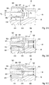
- FIG. 3A to 3C A second embodiment variant is shown, in which the air / fuel supply arrangements 50 are designed on the basis of a high-calorific design point (a design operating point for operation with a high-calorific design fuel, for example natural gas with a calorific value of just under 50 MJ / kg).
- the flow cross section at the fuel orifice 510, or here the diameter d 3 is reduced by the amount compared to the flow cross section or the diameter d 2 of the fuel channel 502 Accelerate fuel flow to a desired speed at fuel orifice 510.
- the diameters d 3 are designed such that the speeds of the (low-calorific or high-calorific design) fuel at the fuel outlet 510 are similar to the speed of the fresh gas mixture at the outlet 512 into the combustion chamber 24 (for example between +/- 50% , especially between +/- 20%).
- the outlet 512 there are typical speeds for a recirculation-stabilized jet flame burner, for example between 60 m / s and 180 m / s.
- the similar entry velocities prevent flow detachments and associated fuel fluctuations at the fuel orifice 510 and support a stable combustion process.
- the bypass channels 526 run here, for example, radially-axially, inclined at an angle ⁇ with respect to the central axis M.
- the angle ⁇ is in the first embodiment ( 2A to 2C ) z. B. between 15 ° and 45 ° ( ⁇ direction opened upstream).
- the angle ⁇ z. B. between 135 ° and 165 ° ( ⁇ direction opened upstream).
- the angle ⁇ and the total flow cross sections of the bypass channels 526 and / or the bypass openings 528 are designed in the first exemplary embodiment with regard to the high calorific design point, in the second exemplary embodiment with regard to the low calorific design point.
- the design is such that the speeds at the fuel orifices 510 in the high caloric or low calorific design point is adapted to the speeds in the low caloric or high caloric design point, ie the speeds are similar.
- the speed ratio at the fuel orifices 510 "low-calorie / high-calorie" is less than a factor of 2, preferably less than a factor of 1.5.
- FIG. 2B shows the flow in the low calorific design point, with a large fuel mass or volume flow.
- Air and fuel are first brought through the air duct 504 or the fuel duct 502 in separate flow sections to the bypass opening.
- the pressure ratios in the air duct 504 and the fuel duct 502 are similar at the low calorific design point, so that the proportion of air flowing through the bypass opening 528 is (essentially) zero. Therefore, there is no, or at most a small, driving force that causes a flow through the bypass openings 528.
- the air flows (at least for the most part) through the air duct 504 and the fuel through the fuel duct 502 essentially separately to the fuel outlet 510, where the fresh gas components are brought together.
- the flow guidance during operation is in the Figures 3B and 3C indicated by arrows.
- Figure 3B shows the flow guidance in the low calorific design point, with a large fuel volume flow. Air and fuel are first brought through the air duct 504 or the fuel duct 502 to the bypass opening 528. Due to the high fuel mass or volume flow, a high pressure drops at the fuel orifice 510. Accordingly, there is an increased pressure upstream in the fuel channel 502, which leads to an increased pressure difference between the fuel channel 502 and the surrounding air channel 504. The pressure difference causes a portion of the fuel to flow through the bypass channels 526 with the bypass openings 528 into the air channel 504 for pressure equalization.
- bypass channels 526 with the bypass openings 528 are in particular with regard to their angle ⁇ and the flow cross sections are designed such that a pressure difference is brought about, by which the fuel flow is divided proportionally such that the speed at the fuel orifice 510 is similar (for example by a factor of 2 or less, preferably by a factor of 1.3 or less) Speed in the high caloric design point is.
- the fuel compositions in the low calorific and in the high calorific design points are preferably extremes between which the fuel compositions move during operation.
- the pressure conditions within the air / fuel supply arrangements 50 adjust accordingly so that the proportion of the respective fresh gas that flows into the flow path of the other fresh gas is so large that the desired adjustment of the speeds occurs.
- the second air / fuel supply arrangement 60 (cf. Fig. 1 and Fig. 5 . 6A, B ) is designed to supply the fresh gas components air and fuel to the second combustion chamber 26 in a swirl flow, ie with a tangential directional component.
- the air / fuel supply arrangement 60 comprises a mixing chamber 608, which is formed on the bottom in the inner wall, upstream, of the combustion chamber 26, so that it opens into the combustion chamber 26 downstream with an outlet 612.
- the mixing space 608 is arranged centrally, on the longitudinal axis L, and is symmetrical to it, in particular cylindrical.
- the mixing space 608 is delimited on the bottom side by a bottom wall 626, which, for example, is oriented perpendicular to the longitudinal axis L.
- the mixing space 608 is delimited on the circumference by a wall 609.
- the mixing space 608 is used for at least partial premixing of the fresh gas components.
- the air channels 604 form a flow connection between the air distribution space 30 and the mixing space 608 and form separate flow sections of the flow path of the air, here as an example for the pilot stage.
- the air channels 604 have a circular cross section, for example.
- the air channels 604 are, for example, axially constant, in a plane perpendicular to the longitudinal axis L, and are oriented tangentially to the cylindrical mixing space 608 in order to impart a tangential directional component to the emerging air flow in order to generate the swirl flow.
- the alignment could additionally have a radial direction component.
- the fuel channels 602 have, for example, a circular cross section and separate flow sections of the flow paths for the fuel.
- the mouths of the air and fuel channels are arranged in a rotationally symmetrical manner with respect to the longitudinal axis L, here offset by 60 ° to one another, for example.
- the fuel channels 602 each run with an end section 601 axially constant in a plane perpendicular to the longitudinal axis L and tangentially, optionally with an additional radial direction component, to the mixing space 608.
- the end sections 601 of the fuel channels 602 are preferably directed tangentially and radially in the same way as the air channels 604. In this way, the fuel can drive the rotational movement of the swirl flow.
- the fuel channels 602 are designed such that the rotational movement of the swirl flow is also driven in the low calorific design point with the higher mass or volume flows.
- the fresh gas components each have similar orders of magnitude for the inflow speeds into the mixing chamber 608, the fuel speed being 10% and 120%, in particular between 15% and 80%, of the air speed, for example.
- the air speed can be, for example, between 50 m / s and 120 m / s and is such that a flame-stabilizing swirl flow is achieved.
- the fuel orifice 614 and the air orifices 610 are arranged axially offset from one another, the axial lower edges of the fuel orifices 614 being arranged further downstream than the axial lower edges of the air orifices 610.
- the air orifices 610 can, for example, adjoin the bottom wall 626 flush with the floor with the axial lower edges. The generally larger air flow can thus advantageously counteract undesired stabilization of a flame at the fuel orifice 610.
- the fuel channels 602 Upstream of the end sections 601, the fuel channels 602 have axial sections 605, which extend from the distributor area 40.
- the distributor area 40 is arranged centrally on the longitudinal axis L and adjoins the rear of the bottom wall 626. The radial extent of the distributor area 40 is greater than that of the mixing chamber 608, so that the fuel flow can be fed to the mixing chamber 608 simply from the distributor region 40 via the axial sections 605 and the downstream end sections 601.
- the distributor area 40 is fed by the second fuel supply 36 arranged centrally on the longitudinal axis L.
- the central arrangement of the fuel supply 36 and the distributor area 40 with its arrangement adjacent to the rear of the bottom wall 626 advantageously enables cooling of the bottom wall 626 by means of the supplied fuel flow, which impinges on the back of the bottom wall 626 when it is supplied and cools it in the manner of an impact cooling.
- the fuel channels 602, which are arranged uniformly around the mixing chamber 608, with the axial sections 605 and end sections 601, likewise contribute to cooling the mixing chamber 608.
- the temperature load in the burner head 4 is advantageously reduced in some areas. Temperature-sensitive components, such as an ignition device or bearing points, can be arranged in these areas. This has a positive influence on the service life of the individual components of the burner system 1.
- the fuel orifices 614 form a group of first supply openings, the fresh gas components fuel and air being brought together in the mixing space 608.
- the second fuel channels 603 are aligned axially to the longitudinal axis L, whereby they can also have a radial component.
- the second fuel orifices 616 are arranged in the mixing space 608, in particular in the bottom wall 626, at a location B (here area) at which a lower pressure prevails in the high-calorific design point than at a location A (here area) of the first fuel orifices 614.
- a place is located e.g. B. flush with the side in the direction of the mixing chamber 608 of the bottom wall 626, radially offset from the longitudinal axis L.
- Such an arrangement results in operation at the high calorific design point a pressure difference through which the fuel preferably flows into the mixing chamber 608 via the second fuel channels 603 and the second fuel orifices 616.
- the flow cross sections or the total flow cross section of the second fuel channels 603 are designed such that the speeds at the second fuel orifices 616 z. B. between 30% and 80% of the speed of the air flow. This advantageously brings about a good mixing of the fuel into the swirled air flow.
- the fuel flow through the second fuel channels 603 is (almost) 100% and through the first fuel channels 602 (almost) 0%.
- Figure 6A shows the operation in the low calorific design point, with high fuel mass flow.
- the fuel flows through the distributor area 40.
- the flow cross sections of the second fuel channels 603 or the second fuel orifices 616 or the total flow cross section (sum of the flow cross sections) is selected such that there is a high pressure loss within the second fuel channels 603 at the low calorific design point.
- the pressure loss caused by the design is so high that a portion, for example between 90% and 30%, of the fuel flows into the mixing chamber 608 via the first fuel channels 602, the fuel at the first fuel orifices 614 having a speed of e.g. B. 10% to 30% of the air flow at the air orifices 610.
- the rotation of the swirl flow is also driven by the high fuel mass flows.
- the other portion of the fuel e.g. B. 10% to 70% flows through the second fuel channels 603.
- the swirl flow of the air entrains the fuel flowing into the mixing space 608 and accelerates it.
- the air velocities are such that flame stabilization is achieved by the swirl flow.
- the proportion of fuel flow through the second fuel channels 603 varies between e.g. B. 10% to 70% and (almost) 100% between the low calorie and the high calorie design point. In this way, stable, pressure-loss-optimized (and thus more efficient) operation can be achieved with the same geometry with low, medium and high-calorie fuels.
- the burner system 1 can be operated stably and reliably with both low and high-calorific fuels and variants in between. Since the adjusted flow through the air / fuel supply arrangements occurs due to the changing pressure conditions with the changing calorific value or Wobbe index without changing the (burner head) geometry, no adjustment or regulation via a control device is advantageously necessary.
Landscapes
- Engineering & Computer Science (AREA)
- Chemical & Material Sciences (AREA)
- Combustion & Propulsion (AREA)
- Mechanical Engineering (AREA)
- General Engineering & Computer Science (AREA)
- Gas Burners (AREA)
- Engine Equipment That Uses Special Cycles (AREA)
- Feeding And Controlling Fuel (AREA)
- Combustion Of Fluid Fuel (AREA)
Applications Claiming Priority (1)
| Application Number | Priority Date | Filing Date | Title |
|---|---|---|---|
| DE102018114870.4A DE102018114870B3 (de) | 2018-06-20 | 2018-06-20 | Brennersystem und Verfahren zur Erzeugung von Heißgas in einer Gasturbinenanlage |
Publications (2)
| Publication Number | Publication Date |
|---|---|
| EP3584501A1 true EP3584501A1 (fr) | 2019-12-25 |
| EP3584501B1 EP3584501B1 (fr) | 2022-12-07 |
Family
ID=66857678
Family Applications (1)
| Application Number | Title | Priority Date | Filing Date |
|---|---|---|---|
| EP19179795.0A Active EP3584501B1 (fr) | 2018-06-20 | 2019-06-12 | Système de brûleur et procédé de production de gaz chaud dans une installation de turbine à gaz |
Country Status (4)
| Country | Link |
|---|---|
| EP (1) | EP3584501B1 (fr) |
| DE (1) | DE102018114870B3 (fr) |
| ES (1) | ES2935763T3 (fr) |
| FI (1) | FI3584501T3 (fr) |
Cited By (1)
| Publication number | Priority date | Publication date | Assignee | Title |
|---|---|---|---|---|
| CN114856826A (zh) * | 2021-02-03 | 2022-08-05 | 通用电气公司 | 用于在增强型燃气涡轮发动机中喷洒燃料的系统和方法 |
Citations (14)
| Publication number | Priority date | Publication date | Assignee | Title |
|---|---|---|---|---|
| US4967561A (en) | 1982-05-28 | 1990-11-06 | Asea Brown Boveri Ag | Combustion chamber of a gas turbine and method of operating it |
| DE4409918A1 (de) | 1994-03-23 | 1995-09-28 | Abb Management Ag | Brenner zum Betrieb einer Brennkammer |
| EP0908671A1 (fr) | 1997-10-08 | 1999-04-14 | Abb Research Ltd. | Procédé de combustion des combustibles gazeux, liquides et combustibles à moyen et bas pouvoir calorifique dans un brûleur |
| EP1255080A1 (fr) * | 2001-04-30 | 2002-11-06 | ALSTOM (Switzerland) Ltd | Brûleur catalytique |
| US6684640B2 (en) | 2000-10-23 | 2004-02-03 | Alstom Power N.V. | Gas turbine engine combustion system |
| US20040068973A1 (en) * | 2001-03-09 | 2004-04-15 | Tsutomu Wakabayashi | Burner and gas turbine engine |
| EP1800062A1 (fr) | 2004-10-11 | 2007-06-27 | Siemens Aktiengesellschaft | Bruleur destine a la combustion d'un gaz combustible a faible pouvoir calorifique et procede pour faire fonctionner un bruleur |
| JP3976464B2 (ja) * | 2000-02-18 | 2007-09-19 | 大阪瓦斯株式会社 | 流体混合器とそれを用いたバーナ装置 |
| EP1892469A1 (fr) | 2006-08-16 | 2008-02-27 | Siemens Aktiengesellschaft | Passage de tourbillonneur et brûleur pour une turbine à gaz |
| EP1995515A1 (fr) | 2007-05-23 | 2008-11-26 | WS-Wärmeprozesstechnik GmbH | Fonctionnement FLOX pris en charge et son brûleur |
| US20100077759A1 (en) * | 2008-09-30 | 2010-04-01 | Arjun Singh | Tubular Fuel Injector for Secondary Fuel Nozzle |
| US20100139238A1 (en) * | 2008-12-04 | 2010-06-10 | General Electric Company | Combustor Housing for Combustion of Low-BTU Fuel Gases and Methods of Making and Using the Same |
| DE102010062351A1 (de) | 2010-12-02 | 2012-06-06 | Deutsches Zentrum für Luft- und Raumfahrt e.V. | Mischungsvorrichtung |
| WO2014027005A2 (fr) | 2012-08-17 | 2014-02-20 | Dürr Systems GmbH | Brûleur |
-
2018
- 2018-06-20 DE DE102018114870.4A patent/DE102018114870B3/de active Active
-
2019
- 2019-06-12 FI FIEP19179795.0T patent/FI3584501T3/de active
- 2019-06-12 EP EP19179795.0A patent/EP3584501B1/fr active Active
- 2019-06-12 ES ES19179795T patent/ES2935763T3/es active Active
Patent Citations (14)
| Publication number | Priority date | Publication date | Assignee | Title |
|---|---|---|---|---|
| US4967561A (en) | 1982-05-28 | 1990-11-06 | Asea Brown Boveri Ag | Combustion chamber of a gas turbine and method of operating it |
| DE4409918A1 (de) | 1994-03-23 | 1995-09-28 | Abb Management Ag | Brenner zum Betrieb einer Brennkammer |
| EP0908671A1 (fr) | 1997-10-08 | 1999-04-14 | Abb Research Ltd. | Procédé de combustion des combustibles gazeux, liquides et combustibles à moyen et bas pouvoir calorifique dans un brûleur |
| JP3976464B2 (ja) * | 2000-02-18 | 2007-09-19 | 大阪瓦斯株式会社 | 流体混合器とそれを用いたバーナ装置 |
| US6684640B2 (en) | 2000-10-23 | 2004-02-03 | Alstom Power N.V. | Gas turbine engine combustion system |
| US20040068973A1 (en) * | 2001-03-09 | 2004-04-15 | Tsutomu Wakabayashi | Burner and gas turbine engine |
| EP1255080A1 (fr) * | 2001-04-30 | 2002-11-06 | ALSTOM (Switzerland) Ltd | Brûleur catalytique |
| EP1800062A1 (fr) | 2004-10-11 | 2007-06-27 | Siemens Aktiengesellschaft | Bruleur destine a la combustion d'un gaz combustible a faible pouvoir calorifique et procede pour faire fonctionner un bruleur |
| EP1892469A1 (fr) | 2006-08-16 | 2008-02-27 | Siemens Aktiengesellschaft | Passage de tourbillonneur et brûleur pour une turbine à gaz |
| EP1995515A1 (fr) | 2007-05-23 | 2008-11-26 | WS-Wärmeprozesstechnik GmbH | Fonctionnement FLOX pris en charge et son brûleur |
| US20100077759A1 (en) * | 2008-09-30 | 2010-04-01 | Arjun Singh | Tubular Fuel Injector for Secondary Fuel Nozzle |
| US20100139238A1 (en) * | 2008-12-04 | 2010-06-10 | General Electric Company | Combustor Housing for Combustion of Low-BTU Fuel Gases and Methods of Making and Using the Same |
| DE102010062351A1 (de) | 2010-12-02 | 2012-06-06 | Deutsches Zentrum für Luft- und Raumfahrt e.V. | Mischungsvorrichtung |
| WO2014027005A2 (fr) | 2012-08-17 | 2014-02-20 | Dürr Systems GmbH | Brûleur |
Cited By (3)
| Publication number | Priority date | Publication date | Assignee | Title |
|---|---|---|---|---|
| CN114856826A (zh) * | 2021-02-03 | 2022-08-05 | 通用电气公司 | 用于在增强型燃气涡轮发动机中喷洒燃料的系统和方法 |
| US11578870B2 (en) | 2021-02-03 | 2023-02-14 | General Electric Company | Systems and methods for spraying fuel in an augmented gas turbine engine |
| CN114856826B (zh) * | 2021-02-03 | 2024-03-15 | 通用电气公司 | 用于在增强型燃气涡轮发动机中喷洒燃料的系统和方法 |
Also Published As
| Publication number | Publication date |
|---|---|
| FI3584501T3 (en) | 2023-01-13 |
| ES2935763T3 (es) | 2023-03-09 |
| EP3584501B1 (fr) | 2022-12-07 |
| DE102018114870B3 (de) | 2019-11-28 |
Similar Documents
| Publication | Publication Date | Title |
|---|---|---|
| DE69210715T2 (de) | Brenner mit geringer NOx-Produktion | |
| EP2116766B1 (fr) | Brûleur avec lance à combustible | |
| DE60007946T2 (de) | Eine Brennkammer | |
| EP1336800B1 (fr) | Procédé de réduction des oscillations induites par la combustion dans les dispositifs de combustion ainsi que brûleur à prémélange pour la mise en oeuvre du procédé | |
| EP2058590B1 (fr) | Procédé de fonctionnement d'un brûleur | |
| EP0781967B1 (fr) | Chambre de combustion annulaire pour turbine à gaz | |
| EP2225488B1 (fr) | Brûleur à prémélange pour une turbine à gaz | |
| DE69306950T2 (de) | Brennkammer und verfahren dafür | |
| EP3559551B1 (fr) | Dispositif de mélange et tête de brûleur pour un brûleur à émission de nox réduite | |
| DE102008037480A1 (de) | Mager vorgemischte Dual-Fuel-Ringrohrbrennkammer mit Radial-Mehrring-Stufendüse | |
| EP2329196B1 (fr) | Brûleur et procédé d'utilisation d'un brûleur | |
| DE102014102780A1 (de) | System und Verfahren zur Luftstromkonditionierung auf Rohniveau | |
| DE102014103083A1 (de) | System und Verfahren zur Luftkonditionierung auf Rohrniveau | |
| DE102010017778A1 (de) | Vorrichtung zur Brennstoffeinspritzung bei einer Turbine | |
| WO2006053866A1 (fr) | Procede pour mettre en marche un bruleur | |
| DE4446945A1 (de) | Gasbetriebener Vormischbrenner | |
| EP0692675A2 (fr) | Procédé et dispositif pour la mise en oeuvre d'un brûleur combiné à combustibles liquides et gazeux | |
| EP3940293B1 (fr) | Procédé de combustion étagée d'un combustible et tête de combustion | |
| EP1730448B1 (fr) | Ensemble a plusieurs bruleurs servant a faire fonctionner une chambre de combustion et procede pour faire fonctionner un tel ensemble | |
| EP2583033B1 (fr) | Brûleur de turbines | |
| EP3584501B1 (fr) | Système de brûleur et procédé de production de gaz chaud dans une installation de turbine à gaz | |
| EP3250857B1 (fr) | Agencement de brûleur | |
| EP4321804B1 (fr) | Ensemble turbine à gaz avec ensemble chambre de combustion et procédé | |
| DE102017120370A1 (de) | Brennerkopf, Brennersystem und Verfahren zum Betreiben des Brennersystems | |
| DE102005061486B4 (de) | Verfahren zum Betreiben einer Brennkammer einer Gasturbine |
Legal Events
| Date | Code | Title | Description |
|---|---|---|---|
| PUAI | Public reference made under article 153(3) epc to a published international application that has entered the european phase |
Free format text: ORIGINAL CODE: 0009012 |
|
| STAA | Information on the status of an ep patent application or granted ep patent |
Free format text: STATUS: THE APPLICATION HAS BEEN PUBLISHED |
|
| AK | Designated contracting states |
Kind code of ref document: A1 Designated state(s): AL AT BE BG CH CY CZ DE DK EE ES FI FR GB GR HR HU IE IS IT LI LT LU LV MC MK MT NL NO PL PT RO RS SE SI SK SM TR |
|
| AX | Request for extension of the european patent |
Extension state: BA ME |
|
| STAA | Information on the status of an ep patent application or granted ep patent |
Free format text: STATUS: REQUEST FOR EXAMINATION WAS MADE |
|
| 17P | Request for examination filed |
Effective date: 20200625 |
|
| RBV | Designated contracting states (corrected) |
Designated state(s): AL AT BE BG CH CY CZ DE DK EE ES FI FR GB GR HR HU IE IS IT LI LT LU LV MC MK MT NL NO PL PT RO RS SE SI SK SM TR |
|
| STAA | Information on the status of an ep patent application or granted ep patent |
Free format text: STATUS: EXAMINATION IS IN PROGRESS |
|
| 17Q | First examination report despatched |
Effective date: 20200921 |
|
| GRAP | Despatch of communication of intention to grant a patent |
Free format text: ORIGINAL CODE: EPIDOSNIGR1 |
|
| STAA | Information on the status of an ep patent application or granted ep patent |
Free format text: STATUS: GRANT OF PATENT IS INTENDED |
|
| INTG | Intention to grant announced |
Effective date: 20220413 |
|
| GRAJ | Information related to disapproval of communication of intention to grant by the applicant or resumption of examination proceedings by the epo deleted |
Free format text: ORIGINAL CODE: EPIDOSDIGR1 |
|
| STAA | Information on the status of an ep patent application or granted ep patent |
Free format text: STATUS: EXAMINATION IS IN PROGRESS |
|
| GRAP | Despatch of communication of intention to grant a patent |
Free format text: ORIGINAL CODE: EPIDOSNIGR1 |
|
| STAA | Information on the status of an ep patent application or granted ep patent |
Free format text: STATUS: GRANT OF PATENT IS INTENDED |
|
| INTC | Intention to grant announced (deleted) | ||
| INTG | Intention to grant announced |
Effective date: 20220830 |
|
| GRAS | Grant fee paid |
Free format text: ORIGINAL CODE: EPIDOSNIGR3 |
|
| GRAA | (expected) grant |
Free format text: ORIGINAL CODE: 0009210 |
|
| STAA | Information on the status of an ep patent application or granted ep patent |
Free format text: STATUS: THE PATENT HAS BEEN GRANTED |
|
| AK | Designated contracting states |
Kind code of ref document: B1 Designated state(s): AL AT BE BG CH CY CZ DE DK EE ES FI FR GB GR HR HU IE IS IT LI LT LU LV MC MK MT NL NO PL PT RO RS SE SI SK SM TR |
|
| REG | Reference to a national code |
Ref country code: GB Ref legal event code: FG4D Free format text: NOT ENGLISH |
|
| REG | Reference to a national code |
Ref country code: CH Ref legal event code: EP Ref country code: AT Ref legal event code: REF Ref document number: 1536516 Country of ref document: AT Kind code of ref document: T Effective date: 20221215 |
|
| REG | Reference to a national code |
Ref country code: DE Ref legal event code: R096 Ref document number: 502019006462 Country of ref document: DE |
|
| REG | Reference to a national code |
Ref country code: FI Ref legal event code: FGE Ref country code: IE Ref legal event code: FG4D Free format text: LANGUAGE OF EP DOCUMENT: GERMAN |
|
| REG | Reference to a national code |
Ref country code: NL Ref legal event code: FP |
|
| REG | Reference to a national code |
Ref country code: SE Ref legal event code: TRGR |
|
| REG | Reference to a national code |
Ref country code: NO Ref legal event code: T2 Effective date: 20221207 |
|
| REG | Reference to a national code |
Ref country code: ES Ref legal event code: FG2A Ref document number: 2935763 Country of ref document: ES Kind code of ref document: T3 Effective date: 20230309 |
|
| REG | Reference to a national code |
Ref country code: LT Ref legal event code: MG9D |
|
| PG25 | Lapsed in a contracting state [announced via postgrant information from national office to epo] |
Ref country code: LT Free format text: LAPSE BECAUSE OF FAILURE TO SUBMIT A TRANSLATION OF THE DESCRIPTION OR TO PAY THE FEE WITHIN THE PRESCRIBED TIME-LIMIT Effective date: 20221207 |
|
| PG25 | Lapsed in a contracting state [announced via postgrant information from national office to epo] |
Ref country code: RS Free format text: LAPSE BECAUSE OF FAILURE TO SUBMIT A TRANSLATION OF THE DESCRIPTION OR TO PAY THE FEE WITHIN THE PRESCRIBED TIME-LIMIT Effective date: 20221207 Ref country code: PL Free format text: LAPSE BECAUSE OF FAILURE TO SUBMIT A TRANSLATION OF THE DESCRIPTION OR TO PAY THE FEE WITHIN THE PRESCRIBED TIME-LIMIT Effective date: 20221207 Ref country code: LV Free format text: LAPSE BECAUSE OF FAILURE TO SUBMIT A TRANSLATION OF THE DESCRIPTION OR TO PAY THE FEE WITHIN THE PRESCRIBED TIME-LIMIT Effective date: 20221207 Ref country code: HR Free format text: LAPSE BECAUSE OF FAILURE TO SUBMIT A TRANSLATION OF THE DESCRIPTION OR TO PAY THE FEE WITHIN THE PRESCRIBED TIME-LIMIT Effective date: 20221207 Ref country code: GR Free format text: LAPSE BECAUSE OF FAILURE TO SUBMIT A TRANSLATION OF THE DESCRIPTION OR TO PAY THE FEE WITHIN THE PRESCRIBED TIME-LIMIT Effective date: 20230308 |
|
| PG25 | Lapsed in a contracting state [announced via postgrant information from national office to epo] |
Ref country code: SM Free format text: LAPSE BECAUSE OF FAILURE TO SUBMIT A TRANSLATION OF THE DESCRIPTION OR TO PAY THE FEE WITHIN THE PRESCRIBED TIME-LIMIT Effective date: 20221207 Ref country code: RO Free format text: LAPSE BECAUSE OF FAILURE TO SUBMIT A TRANSLATION OF THE DESCRIPTION OR TO PAY THE FEE WITHIN THE PRESCRIBED TIME-LIMIT Effective date: 20221207 Ref country code: PT Free format text: LAPSE BECAUSE OF FAILURE TO SUBMIT A TRANSLATION OF THE DESCRIPTION OR TO PAY THE FEE WITHIN THE PRESCRIBED TIME-LIMIT Effective date: 20230410 Ref country code: EE Free format text: LAPSE BECAUSE OF FAILURE TO SUBMIT A TRANSLATION OF THE DESCRIPTION OR TO PAY THE FEE WITHIN THE PRESCRIBED TIME-LIMIT Effective date: 20221207 Ref country code: CZ Free format text: LAPSE BECAUSE OF FAILURE TO SUBMIT A TRANSLATION OF THE DESCRIPTION OR TO PAY THE FEE WITHIN THE PRESCRIBED TIME-LIMIT Effective date: 20221207 |
|
| PG25 | Lapsed in a contracting state [announced via postgrant information from national office to epo] |
Ref country code: SK Free format text: LAPSE BECAUSE OF FAILURE TO SUBMIT A TRANSLATION OF THE DESCRIPTION OR TO PAY THE FEE WITHIN THE PRESCRIBED TIME-LIMIT Effective date: 20221207 Ref country code: IS Free format text: LAPSE BECAUSE OF FAILURE TO SUBMIT A TRANSLATION OF THE DESCRIPTION OR TO PAY THE FEE WITHIN THE PRESCRIBED TIME-LIMIT Effective date: 20230407 Ref country code: AL Free format text: LAPSE BECAUSE OF FAILURE TO SUBMIT A TRANSLATION OF THE DESCRIPTION OR TO PAY THE FEE WITHIN THE PRESCRIBED TIME-LIMIT Effective date: 20221207 |
|
| REG | Reference to a national code |
Ref country code: DE Ref legal event code: R097 Ref document number: 502019006462 Country of ref document: DE |
|
| PLBE | No opposition filed within time limit |
Free format text: ORIGINAL CODE: 0009261 |
|
| STAA | Information on the status of an ep patent application or granted ep patent |
Free format text: STATUS: NO OPPOSITION FILED WITHIN TIME LIMIT |
|
| PG25 | Lapsed in a contracting state [announced via postgrant information from national office to epo] |
Ref country code: DK Free format text: LAPSE BECAUSE OF FAILURE TO SUBMIT A TRANSLATION OF THE DESCRIPTION OR TO PAY THE FEE WITHIN THE PRESCRIBED TIME-LIMIT Effective date: 20221207 |
|
| 26N | No opposition filed |
Effective date: 20230908 |
|
| PG25 | Lapsed in a contracting state [announced via postgrant information from national office to epo] |
Ref country code: SI Free format text: LAPSE BECAUSE OF FAILURE TO SUBMIT A TRANSLATION OF THE DESCRIPTION OR TO PAY THE FEE WITHIN THE PRESCRIBED TIME-LIMIT Effective date: 20221207 |
|
| PG25 | Lapsed in a contracting state [announced via postgrant information from national office to epo] |
Ref country code: MC Free format text: LAPSE BECAUSE OF FAILURE TO SUBMIT A TRANSLATION OF THE DESCRIPTION OR TO PAY THE FEE WITHIN THE PRESCRIBED TIME-LIMIT Effective date: 20221207 |
|
| PG25 | Lapsed in a contracting state [announced via postgrant information from national office to epo] |
Ref country code: MC Free format text: LAPSE BECAUSE OF FAILURE TO SUBMIT A TRANSLATION OF THE DESCRIPTION OR TO PAY THE FEE WITHIN THE PRESCRIBED TIME-LIMIT Effective date: 20221207 |
|
| PG25 | Lapsed in a contracting state [announced via postgrant information from national office to epo] |
Ref country code: LU Free format text: LAPSE BECAUSE OF NON-PAYMENT OF DUE FEES Effective date: 20230612 |
|
| REG | Reference to a national code |
Ref country code: IE Ref legal event code: MM4A |
|
| PG25 | Lapsed in a contracting state [announced via postgrant information from national office to epo] |
Ref country code: LU Free format text: LAPSE BECAUSE OF NON-PAYMENT OF DUE FEES Effective date: 20230612 |
|
| PG25 | Lapsed in a contracting state [announced via postgrant information from national office to epo] |
Ref country code: IE Free format text: LAPSE BECAUSE OF NON-PAYMENT OF DUE FEES Effective date: 20230612 |
|
| PG25 | Lapsed in a contracting state [announced via postgrant information from national office to epo] |
Ref country code: IE Free format text: LAPSE BECAUSE OF NON-PAYMENT OF DUE FEES Effective date: 20230612 |
|
| PG25 | Lapsed in a contracting state [announced via postgrant information from national office to epo] |
Ref country code: BG Free format text: LAPSE BECAUSE OF FAILURE TO SUBMIT A TRANSLATION OF THE DESCRIPTION OR TO PAY THE FEE WITHIN THE PRESCRIBED TIME-LIMIT Effective date: 20221207 |
|
| PG25 | Lapsed in a contracting state [announced via postgrant information from national office to epo] |
Ref country code: BG Free format text: LAPSE BECAUSE OF FAILURE TO SUBMIT A TRANSLATION OF THE DESCRIPTION OR TO PAY THE FEE WITHIN THE PRESCRIBED TIME-LIMIT Effective date: 20221207 |
|
| PGFP | Annual fee paid to national office [announced via postgrant information from national office to epo] |
Ref country code: NL Payment date: 20250515 Year of fee payment: 7 |
|
| PGFP | Annual fee paid to national office [announced via postgrant information from national office to epo] |
Ref country code: FI Payment date: 20250527 Year of fee payment: 7 |
|
| PGFP | Annual fee paid to national office [announced via postgrant information from national office to epo] |
Ref country code: DE Payment date: 20250509 Year of fee payment: 7 |
|
| PGFP | Annual fee paid to national office [announced via postgrant information from national office to epo] |
Ref country code: GB Payment date: 20250508 Year of fee payment: 7 |
|
| PGFP | Annual fee paid to national office [announced via postgrant information from national office to epo] |
Ref country code: NO Payment date: 20250526 Year of fee payment: 7 |
|
| PGFP | Annual fee paid to national office [announced via postgrant information from national office to epo] |
Ref country code: BE Payment date: 20250513 Year of fee payment: 7 |
|
| PGFP | Annual fee paid to national office [announced via postgrant information from national office to epo] |
Ref country code: FR Payment date: 20250512 Year of fee payment: 7 |
|
| PGFP | Annual fee paid to national office [announced via postgrant information from national office to epo] |
Ref country code: AT Payment date: 20250526 Year of fee payment: 7 |
|
| PG25 | Lapsed in a contracting state [announced via postgrant information from national office to epo] |
Ref country code: CY Free format text: LAPSE BECAUSE OF FAILURE TO SUBMIT A TRANSLATION OF THE DESCRIPTION OR TO PAY THE FEE WITHIN THE PRESCRIBED TIME-LIMIT; INVALID AB INITIO Effective date: 20190612 |
|
| PGFP | Annual fee paid to national office [announced via postgrant information from national office to epo] |
Ref country code: SE Payment date: 20250609 Year of fee payment: 7 |
|
| PG25 | Lapsed in a contracting state [announced via postgrant information from national office to epo] |
Ref country code: HU Free format text: LAPSE BECAUSE OF FAILURE TO SUBMIT A TRANSLATION OF THE DESCRIPTION OR TO PAY THE FEE WITHIN THE PRESCRIBED TIME-LIMIT; INVALID AB INITIO Effective date: 20190612 |
|
| PGFP | Annual fee paid to national office [announced via postgrant information from national office to epo] |
Ref country code: ES Payment date: 20250709 Year of fee payment: 7 |
|
| PGFP | Annual fee paid to national office [announced via postgrant information from national office to epo] |
Ref country code: IT Payment date: 20250610 Year of fee payment: 7 |
|
| PGFP | Annual fee paid to national office [announced via postgrant information from national office to epo] |
Ref country code: CH Payment date: 20250701 Year of fee payment: 7 |
|
| PG25 | Lapsed in a contracting state [announced via postgrant information from national office to epo] |
Ref country code: TR Free format text: LAPSE BECAUSE OF FAILURE TO SUBMIT A TRANSLATION OF THE DESCRIPTION OR TO PAY THE FEE WITHIN THE PRESCRIBED TIME-LIMIT Effective date: 20221207 |