EP3584501B1 - Système de brûleur et procédé de production de gaz chaud dans une installation de turbine à gaz - Google Patents
Système de brûleur et procédé de production de gaz chaud dans une installation de turbine à gaz Download PDFInfo
- Publication number
- EP3584501B1 EP3584501B1 EP19179795.0A EP19179795A EP3584501B1 EP 3584501 B1 EP3584501 B1 EP 3584501B1 EP 19179795 A EP19179795 A EP 19179795A EP 3584501 B1 EP3584501 B1 EP 3584501B1
- Authority
- EP
- European Patent Office
- Prior art keywords
- fuel
- oxidizer
- flow
- opening
- calorific
- Prior art date
- Legal status (The legal status is an assumption and is not a legal conclusion. Google has not performed a legal analysis and makes no representation as to the accuracy of the status listed.)
- Active
Links
Images



Classifications
-
- F—MECHANICAL ENGINEERING; LIGHTING; HEATING; WEAPONS; BLASTING
- F23—COMBUSTION APPARATUS; COMBUSTION PROCESSES
- F23R—GENERATING COMBUSTION PRODUCTS OF HIGH PRESSURE OR HIGH VELOCITY, e.g. GAS-TURBINE COMBUSTION CHAMBERS
- F23R3/00—Continuous combustion chambers using liquid or gaseous fuel
- F23R3/28—Continuous combustion chambers using liquid or gaseous fuel characterised by the fuel supply
- F23R3/286—Continuous combustion chambers using liquid or gaseous fuel characterised by the fuel supply having fuel-air premixing devices
-
- F—MECHANICAL ENGINEERING; LIGHTING; HEATING; WEAPONS; BLASTING
- F23—COMBUSTION APPARATUS; COMBUSTION PROCESSES
- F23R—GENERATING COMBUSTION PRODUCTS OF HIGH PRESSURE OR HIGH VELOCITY, e.g. GAS-TURBINE COMBUSTION CHAMBERS
- F23R3/00—Continuous combustion chambers using liquid or gaseous fuel
- F23R3/28—Continuous combustion chambers using liquid or gaseous fuel characterised by the fuel supply
- F23R3/34—Feeding into different combustion zones
- F23R3/343—Pilot flames, i.e. fuel nozzles or injectors using only a very small proportion of the total fuel to insure continuous combustion
-
- F—MECHANICAL ENGINEERING; LIGHTING; HEATING; WEAPONS; BLASTING
- F23—COMBUSTION APPARATUS; COMBUSTION PROCESSES
- F23R—GENERATING COMBUSTION PRODUCTS OF HIGH PRESSURE OR HIGH VELOCITY, e.g. GAS-TURBINE COMBUSTION CHAMBERS
- F23R2900/00—Special features of, or arrangements for continuous combustion chambers; Combustion processes therefor
- F23R2900/03282—High speed injection of air and/or fuel inducing internal recirculation
-
- F—MECHANICAL ENGINEERING; LIGHTING; HEATING; WEAPONS; BLASTING
- F23—COMBUSTION APPARATUS; COMBUSTION PROCESSES
- F23R—GENERATING COMBUSTION PRODUCTS OF HIGH PRESSURE OR HIGH VELOCITY, e.g. GAS-TURBINE COMBUSTION CHAMBERS
- F23R2900/00—Special features of, or arrangements for continuous combustion chambers; Combustion processes therefor
- F23R2900/03342—Arrangement of silo-type combustion chambers
Definitions
- the invention relates to a burner system for generating hot gas in a gas turbine system, with a combustion chamber that includes a combustion chamber aligned along a longitudinal axis, and with a burner head with at least one oxidizer/fuel supply arrangement for supplying oxidizer and fuel as fresh gas components into the combustion chamber one flow path each for fuel and oxidizer for feeding them into the combustion chamber, with the flow paths upstream of a mixing chamber each having separate flow sections for separate routing of the fresh gas components, and the flow paths in the mixing chamber are combined, and at least one first feed opening for feeding fuel into the mixing room.
- the invention also relates to a corresponding method for generating hot gas in a gas turbine system.
- JP 3 976464 B2 discloses a combustor having a fluid mixer including a plurality of feed ports. A design for operation with fuels of different calorific values is not specified.
- the U.S. 2010/139238 A1 discloses a burner for operation with a low-calorific fuel which is also operable with a high-calorific fuel.
- the fuels with different calorific values are introduced into the combustion chamber via different fuel feeds.
- the arrangement and / or design of the other flow section is such that the proportion when introducing fuel with a different calorific value (or a different Wobbe index) due to changing aerodynamic Conditions, especially the pressure conditions, changes.
- the geometry remains unchanged, in particular the flow cross sections of the flow sections remain constant.
- different fuels can advantageously be supplied via the same oxidizer/fuel supply arrangements. This advantageously allows the use of changing fuels and/or mixed operation, e.g. B. with a continuous change in the fuel composition, with little effort and during operation.
- the (respective) further flow section is designed, in particular arranged and/or formed (e.g. with a corresponding flow cross section) according to the desired division or proportions.
- e.g. B. (initially) an approximate pressure drop calculation and/or (subsequently) an iterative approach to a design goal, e.g. B. by means of computer-aided flow simulation and / or experimentally.
- the design goal can be, for example, maintaining a certain speed range between the different design points.
- the design goal is that the proportion can be changed in such a way that the speeds at the first and/or at the further feed opening between a low-calorific design point and a high-calorific design point by a maximum of a factor of 2 (speed with low-calorific to speed with high-calorific Fuel), in particular by a maximum of a factor of 1.5, preferably a maximum of a factor of 1.2, deviate from one another, ie the speeds in the different design points are similar to one another.
- the “low-calorific design point” corresponds to a design operating point with a low-calorific design fuel, for example a synthesis gas, with a mass-specific calorific value of approx. 5 MJ/kg.
- the proportion of oxidizer can result, for example, in such a way that the oxidizer mass flow through the bypass channel corresponds to up to 5 times the fuel mass flow. It has been shown that in the case of fuel compositions with a calorific value or Wobbe index between that of the low-calorific and the high-calorific fuel, a correspondingly lower proportion is established, which leads to similar speeds.
- the following advantageous method results, for example, with the fuel orifice expediently having a reduced flow cross section of the fuel orifice compared to the fuel channel:
- fuel and oxidizer flow separately up to to the fuel orifice and are completely brought together there.
- the pressure conditions in the oxidizer and fuel channels are similar in the high calorific design point.
- an aerodynamic obstruction of the further flow section with the bypass opening results.
- the proportion of fresh gas, here fuel, flowing through the bypass opening is (essentially) zero.
- the oxidizer channel preferably comprises a first section in its axial course and a second section downstream of the first section, with a cross-sectional reduction being arranged between the two sections.
- the fuel orifice is arranged axially on, within or downstream of the cross-sectional reduction.
- the reduction in cross section can be designed, for example, as a step, conical or continuous. This arrangement of the fuel orifice means that the fuel is (completely) added to the flow that is accelerated immediately downstream or to the flow that has already been accelerated. This advantageously counteracts (undesirable) flame stabilization at the fuel orifice.
- an oxidator orifice of the oxidator channel and the first fuel orifice are preferably arranged axially offset from one another, particularly if there are several oxidator or fuel channels, with the axial lower edge of the oxidator orifice being arranged upstream of the axial lower edge of the fuel orifice.
- the lower edge of the oxidizer outlet can be flush with the bottom wall, for example. In this way, the fuel flow can be entrained by the swirling oxidizer flow.
- a certain distance from the bottom wall remains, and in particular the thermal load on the bottom wall is reduced by the intermediate air flow.
- the overall flow cross-section of the first fuel orifice is designed in such a way that the inflow velocity of the fuel into the mixing chamber at the low-calorific design point is between 10% and 120%, in particular between 15% and 80% of the velocity of the oxidizer at the oxidator orifice.
- the speed of the oxidizer is such that sufficient swirl generation for flame stabilization is achieved and can be between 50 m/s and 120 m/s, for example.
- the total flow cross-section results from the sum of the flow cross-sections of certain flow sections or orifices, here the first fuel orifices that are present.
- the impulse of the high fuel mass or volume flow can thus advantageously contribute effectively to the generation of swirl.
- it is avoided that the rotational movement of the oxidizer flow is slowed down by the high fuel flow, which could impair flame stabilization.
- the further feed opening is formed by a second fuel orifice into the mixing chamber and the further flow section comprises a second fuel channel which is connected with an axial directional component, e.g. B. parallel to the longitudinal axis.
- an axial directional component e.g. B. parallel to the longitudinal axis.
- the overall flow cross-section of the second fuel port is preferably such that the velocity at the high calorific design point z. B. is between 30% and 80% of the velocity of the oxidizer at the oxidizer orifice.
- the total flow cross section of the second fuel port and/or the second fuel channel is smaller than the (total) flow cross section of the first fuel channel, and is z. B.
- the second fuel port is preferably arranged in the mixing space at a location at which a lower pressure prevails in a high-calorific design point (or with pure oxidizer flow) than at a location of the first fuel port.
- the location can, in particular when there are several (first and/or second) fuel orifices, also be an area.
- the pressure may be between 0.1% and 2% lower than at the location of the first fuel port.
- a portion for example more than 30%, in particular more than 50%
- the remaining portion flows via the second fuel duct/fuel ducts.
- the high fuel flow in the low-calorific design point supports the rotational movement. If the entire fuel flow were introduced in the low-calorific design point via axial fuel channels, the angular momentum of the air would not be sufficient to cause the rotational movement maintained to such an extent that stable combustion would be achieved.
- the peripheral wall 20 runs coaxially to an outer wall 14 of the combustion chamber 6, which is arranged around the peripheral wall 20 to form a circumferential gap, here in the form of a circular ring.
- the gap forms a feeder duct 16 for the countercurrent supply of air into an air distribution space 30 of a burner head 4.
- a different configuration of the air supply is also possible.
- the burner head 4 includes here, for example, separate air/fuel supply arrangements 50, 60.
- the air/fuel supply arrangements 50 are assigned to a main stage of the burner system 1 and are used to add the fresh gas components Air and fuel into the combustion chamber 24.
- the air/fuel supply arrangements 50 ten in number in the present example, are arranged equidistantly on an imaginary circular ring to form a nozzle ring. This arrangement advantageously contributes to a small axial extent of the combustion zone.
- the air/fuel supply arrangement 60 is assigned to a (stabilizing) pilot stage of the burner system 1 and serves to supply the fresh gas components air and fuel to a second (pilot) combustion chamber 26.
- the second combustion chamber 26 is arranged upstream of the combustion chamber 24 and opens into the combustion chamber 24 with an opening 28, wherein in the present case it is embodied on the longitudinal axis L and symmetrically, in particular cylindrically, thereto.
- the air/fuel assemblies 50 are arranged with air ducts 504 circumferentially around the second combustion chamber 26 .
- the air ducts 504 and the combustion chamber 26 are here, for example, incorporated into a burner head body 25 made of solid material. Another configuration is also possible, for example with (thinner) walls. At stationary operating points, the larger air and fuel mass flow is usually routed through the main stage.
- the fuel orifices 510 each form first feed openings for feeding fuel into the air flow. Upstream of the fuel ports 510, the flow paths of the fresh gas components run at least partially in separate flow sections. Mixing spaces 508 are formed in the air passages 504 downstream of the fuel ports 510, in which the flow paths of air and fuel are merged, i. H. in the mixing chambers, the entire fuel flow is introduced into the air flow.
- the mixing chambers 508 are used for the at least partial premixing of fuel and air upstream of their feed into the combustion chamber 6 or the combustion chamber 24.
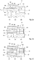
- FIG. 3A to 3C a second embodiment variant is shown, in which the air/fuel supply arrangements 50 are designed starting from a high-calorific design point (a design operating point for operation with a high-calorific design fuel, for example natural gas with a calorific value of just under 50 MJ/kg).
- the flow cross section at the fuel orifice 510, or here the diameter d 3 is reduced compared to the flow cross section or the diameter d 2 of the fuel channel 502 by the Accelerate fuel flow to a desired velocity at fuel orifice 510.
- the bypass channels 526 here run radially-axially, for example, inclined at an angle ⁇ with respect to the central axis M.
- the angle ⁇ is ( Figures 2A to 2C ) e.g. B. between 15 ° and 45 ° (open ⁇ direction upstream).
- the angle ⁇ and the total flow cross-sections of the bypass channels 526 and/or the bypass openings 528 are designed with respect to the high-calorific design point in the first exemplary embodiment and with respect to the low-calorific design point in the second exemplary embodiment.
- the design is such that the velocities at the fuel orifices 510 in the high-caloric or low-caloric design point is matched to the velocities in the low-caloric or high-caloric design point, ie the velocities are similar.
- the "low calorific/high calorific" velocity ratio at the fuel orifices 510 is less than a factor of 2, preferably less than a factor of 1.5.
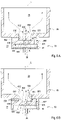
- the second air/fuel supply arrangement 60 (cf. 1 and figure 5 , 6A, B ) is designed to supply the fresh gas components, air and fuel, to the second combustion chamber 26 in a swirling flow, ie with a tangential directional component.
- the air/fuel supply arrangement 60 comprises a mixing chamber 608 which is formed on the bottom side in the inner wall, upstream, of the combustion chamber 26 so that it opens into the combustion chamber 26 downstream with an outlet 612 .
- the mixing chamber 608 is arranged centrally, on the longitudinal axis L, and is embodied symmetrically to this, in particular cylindrically.
- the air ducts 604 with air openings 610, three in number here by way of example, open out into the mixing chamber 608 in the wall 609 on the peripheral side.
- the air channels 604 form a flow connection between the air distribution space 30 and the mixing space 608 and form separate flow sections of the flow path of the air, here by way of example for the pilot stage.
- the air ducts 604 have a circular cross section, for example.
- the air ducts 604 run, for example, axially constant, in a plane perpendicular to the longitudinal axis L, and are aligned tangentially to the cylindrical mixing space 608 in order to impress the exiting air flow with a tangential directional component for generating the swirl flow.
- the alignment could also have a radial directional component.
- the distribution area 40 is fed by the second fuel feed 36 arranged centrally on the longitudinal axis L.
- FIG. The central arrangement of the fuel feed 36 and the distributor area 40 with its arrangement adjacent to the rear of the bottom wall 626 advantageously enables cooling of the bottom wall 626 by means of the supplied fuel flow, which impinges on the rear of the bottom wall 626 and cools it in the manner of impingement cooling.
- the fuel orifices 614 form a group of first supply openings, with the fresh gas components fuel and air being brought together in the mixing space 608 .
- further flow sections, formed by second fuel channels 603, are present, which each open into the mixing chamber 608 of a group via further feed openings, formed by second fuel ports 616.
- the second fuel channels 603 are aligned axially with respect to the longitudinal axis L, although they can also have a radial component.
- Figure 6A shows the operation in the low calorific design point, with high fuel mass flow.
- the fuel flows through the distribution area 40.
- the flow cross sections of the second fuel channels 603 or the second fuel openings 616 or the total flow cross section (sum of the flow cross sections) is selected in such a way that there is a high pressure loss within the second fuel channels 603 at the low-calorific design point.
- the pressure loss caused by the design is so high that a proportion, for example between 90% and 30%, of the fuel flows into the mixing chamber 608 via the first fuel channels 602, the fuel at the first fuel ports 614 having a speed of z. B. 10% to 30% of the air flow at the air ports 610 has.
- the rotation of the swirl flow is thus driven by the high fuel mass flows.
- the other portion of the fuel e.g. B. 10% to 70%, flows via the second fuel channels 603.
- the burner system 1 can be operated stably and reliably with both low-calorific and high-calorific fuels and variants in between. Since the adjusted flow through the air/fuel supply arrangements is set due to the changing pressure conditions with the changing calorific value or Wobbe index without changing the (burner head) geometry, no adjustment or regulation via a control or regulating device is advantageously required.
Landscapes
- Engineering & Computer Science (AREA)
- Chemical & Material Sciences (AREA)
- Combustion & Propulsion (AREA)
- Mechanical Engineering (AREA)
- General Engineering & Computer Science (AREA)
- Engine Equipment That Uses Special Cycles (AREA)
- Feeding And Controlling Fuel (AREA)
- Gas Burners (AREA)
- Combustion Of Fluid Fuel (AREA)
Claims (17)
- Système de brûleur (1) permettant de générer du gaz chaud dans une installation de turbine à gaz, comportant une chambre de combustion (6) qui comprend un espace de combustion (24, 26) aligné le long d'un axe longitudinal (L), et comportant une tête de brûleur (4) comportant au moins un agencement d'acheminement d'oxydant/de combustible (50) pour l'acheminement d'oxydant et de combustible en tant que composants de gaz frais dans la chambre de combustion (6), comprenant- respectivement un trajet d'écoulement pour le combustible et l'oxydant pour les acheminer dans l'espace de combustion (24, 26), les trajets d'écoulement présentant, en amont d'un espace de mélange (508), des sections d'écoulement respectivement séparées pour la conduite séparée des composants de gaz frais, et les trajets d'écoulement étant fusionnés dans l'espace de mélange (508), et- au moins une première ouverture d'acheminement pour l'acheminement de combustible dans l'espace de mélange (508), l'agencement d'acheminement d'oxydant/de combustible (50) comprenant au moins une section d'écoulement supplémentaire comportant une ouverture d'acheminement supplémentaire, par l'intermédiaire de laquelle section d'acheminement une partie de l'un des composants de gaz frais peut être acheminée dans une section d'écoulement avec l'autre composant de gaz frais pour l'acheminement dans l'espace de combustion (24, 26), la section d'écoulement supplémentaire étant disposée et conçue de telle sorte que la partie du composant de gaz frais qui s'écoule par l'intermédiaire de la section d'écoulement supplémentaire, lorsque la géométrie est inchangée, peut être changée par la valeur calorifique du combustible en raison d'un rapport de compression changeant, de telle manière que les vitesses au niveau de la première ouverture d'acheminement et/ou au niveau de l'ouverture d'acheminement supplémentaire diffèrent les unes des autres d'au plus d'un facteur de 2, en particulier d'au plus d'un facteur de 1,5, de préférence d'au plus d'un facteur de 1,2, entre un point de conception à faible pouvoir calorifique et un point de conception à haut pouvoir calorifique,- le point de conception à faible pouvoir calorifique correspondant à un point de fonctionnement de conception comportant un combustible de conception à faible pouvoir calorifique dont la valeur calorifique spécifique à la masse est d'environ 5 MJ/kg, et le point de conception à haut pouvoir calorifique correspondant à un point de fonctionnement de conception comportant un combustible de conception à haut pouvoir calorifique dont la valeur calorifique spécifique à la masse est légèrement inférieure à 50 MJ/kg,- les performances thermiques des deux points de conception correspondant l'une à l'autre, et- l'ouverture d'acheminement supplémentaire étant formée par au moins une ouverture de dérivation (528), l'ouverture de dérivation (528) étant réalisée en amont d'un orifice de combustible (510) d'un canal de combustible (502) dans une paroi (501) de celui-ci, et la section d'écoulement supplémentaire formant une liaison par écoulement entre les trajets d'écoulement de l'oxydant et du combustible.
- Système de brûleur (1) permettant de générer du gaz chaud dans une installation de turbine à gaz, comportant une chambre de combustion (6) qui comprend un espace de combustion (24, 26) aligné le long d'un axe longitudinal (L), et comportant une tête de brûleur (4) comportant au moins un agencement d'acheminement d'oxydant/de combustible (60) pour l'acheminement d'oxydant et de combustible en tant que composants de gaz frais dans la chambre de combustion (6), comprenant- respectivement un trajet d'écoulement pour le combustible et l'oxydant pour les acheminer dans l'espace de combustion (24, 26), les trajets d'écoulement présentant, en amont d'un espace de mélange (608), des sections d'écoulement respectivement séparées pour la conduite séparée des composants de gaz frais, et les trajets d'écoulement étant fusionnés dans l'espace de mélange (608), et- au moins une première ouverture d'acheminement pour l'acheminement de combustible dans l'espace de mélange (608), la première ouverture d'acheminement étant formée par un premier orifice de combustible (614), l'agencement d'acheminement d'oxydant/de combustible (60) comprenant au moins une section d'écoulement supplémentaire comportant une ouverture d'acheminement supplémentaire, par l'intermédiaire de laquelle section d'acheminement une partie de l'un des composants de gaz frais peut être acheminée dans une section d'écoulement avec l'autre composant de gaz frais pour l'acheminement dans l'espace de combustion (24, 26), la section d'écoulement supplémentaire étant disposée et conçue de telle manière que la partie du composant de gaz frais qui s'écoule par l'intermédiaire de la section d'écoulement supplémentaire, lorsque la géométrie est inchangée, peut être changée par la valeur calorifique du combustible en raison d'un rapport de compression changeant, de telle manière que les vitesses au niveau de la première ouverture d'acheminement et/ou au niveau de l'ouverture d'acheminement supplémentaire diffèrent les unes des autres d'au plus d'un facteur de 2, en particulier d'au plus d'un facteur de 1,5, de préférence d'au plus d'un facteur de 1,2, entre un point de conception à faible pouvoir calorifique et un point de conception à haut pouvoir calorifique,- le point de conception à faible pouvoir calorifique correspondant à un point de fonctionnement de conception comportant un combustible de conception à faible pouvoir calorifique dont la valeur calorifique spécifique à la masse est d'environ 5 MJ/kg, et le point de conception à haut pouvoir calorifique correspondant à un point de fonctionnement de conception comportant un combustible de conception à haut pouvoir calorifique dont la valeur calorifique spécifique à la masse est légèrement inférieure à 50 MJ/kg,- les performances thermiques des deux points de conception correspondant l'une à l'autre,- l'espace de mélange (608) étant disposé au centre de l'axe longitudinal (L) et lui étant symétrique, et étant délimité côté fond par une paroi de fond (626), de préférence alignée perpendiculairement à l'axe longitudinal (L), et côté circonférence par une paroi (609), et débouchant en aval avec une sortie (612) dans l'espace de combustion (26), les composants de gaz frais pouvant être acheminés vers l'espace de mélange (608) de telle manière qu'un écoulement tourbillonnaire est généré avec une composante directionnelle tangentielle, et- l'ouverture d'acheminement supplémentaire étant formée par un second orifice de combustible (616) dans l'espace de mélange (608), la section d'écoulement supplémentaire comprenant un second canal de combustible (603) aligné avec une composante directionnelle axiale par rapport à l'axe longitudinal (L).
- Système de brûleur (1) selon la revendication 1,
caractérisé en ce
que l'agencement d'acheminement d'oxydant/de combustible (50) présente un canal d'oxydant (504) comportant une sortie (512) permettant de déboucher dans la chambre de combustion (6), le canal d'oxydant (504) étant aligné avec une section d'évacuation (516) le long d'un axe central (M) s'étendant parallèlement à l'axe longitudinal (L) de manière sensiblement axiale. - Système de brûleur (1) selon la revendication 3,
caractérisé en ce
que l'agencement d'acheminement d'oxydant/de combustible (50) présente le canal de combustible (502) délimité par la paroi (501), lequel s'étend parallèlement, en particulier coaxialement, au canal d'oxydant (504) au moins avec une section d'extrémité (503) dans le canal d'oxydant (504) et débouche avec l'orifice de combustible (510) à l'intérieur du canal d'oxydant (504) ou au niveau de sa sortie (512), l'orifice de combustible (510) formant la première ouverture d'acheminement. - Système de brûleur (1) selon la revendication 4,
caractérisé en ceque l'orifice de combustible (510) présente une section transversale d'écoulement, en particulier d'un diamètre (d3), qui est réduite par rapport à la section transversale d'écoulement, en particulier d'un diamètre (d2), du canal de combustible (502) s'étendant en amont, ouque l'orifice de combustible (510) présente une section transversale d'écoulement, en particulier d'un diamètre (d3), correspondant à la section transversale d'écoulement, en particulier d'un diamètre (d2), du canal de combustible (502) s'étendant en amont. - Système de brûleur (1) selon l'une des revendications 1 ou 3 à 5,
caractérisé en ce
que la section transversale d'écoulement de l'orifice de combustible (510) est conçue de telle sorte qu'au point de conception à faible pouvoir calorifique ou au point de conception à haut pouvoir calorifique, la vitesse au niveau de l'orifice de combustible (510) est de +/-50 %, de préférence de +/-20 %, de la vitesse du mélange de gaz frais au niveau de la sortie (512) dans l'espace de combustion (24), la partie s'écoulant à travers l'ouverture de dérivation (528) étant égale à zéro. - Système de brûleur (1) selon l'une des revendications précédentes,
caractérisé en ce
que plusieurs sections d'écoulement supplémentaires sont prévues, lesquelles sont disposées en particulier symétriquement les unes par rapport aux autres, par exemple symétriquement en rotation autour de l'axe central (M) et axialement à la même hauteur. - Système de brûleur (1) selon l'une des revendications 1 ou 3 à 7,
caractérisé en ceque l'ouverture de dérivation (528) est disposée axialement à l'intérieur du canal d'oxydant (504) en aval d'une section d'admission (514) du canal d'oxydant (504) qui présente de préférence une longueur axiale telle que des effets d'entrée du flux d'oxydant, lorsqu'il est admis dans le canal d'oxydant (504), en particulier dans des séparations d'écoulement locales, sont sensiblement diminués au niveau de l'ouverture de dérivation (528), et/ouque l'ouverture de dérivation (528) est disposée axialement à l'intérieur du canal d'oxydant (504) en amont d'une section d'évacuation (516) de la section d'extrémité (503) qui présente de préférence une longueur axiale telle que des effets d'entrée, lorsqu'un composant de gaz frais est admis dans l'autre, sont sensiblement diminués jusqu'à l'orifice de combustible (510). - Système de brûleur (1) selon l'une des revendications 1 ou 3 à 8,
caractérisé en ce
que la section d'écoulement supplémentaire comprend un canal de dérivation (526) dans la paroi (501) qui s'étend radialement axialement à un angle (a) par rapport à l'axe central (M). - Système de brûleur (1) selon la revendication 9,
caractérisé en ceque l'angle (α) est compris entre 0 et 90°, en particulier entre 10 et 60°, par exemple entre 15 et 45°, ouque l'angle (a) est compris entre 90 et 180°, en particulier entre 110 et 170°, par exemple entre 135 et 165°. - Système de brûleur (1) selon l'une des revendications 3 à 10,
caractérisé en ceque le canal d'oxydant (504) comprend, dans son parcours axial, une première section (520) et une seconde section (522) en aval de la première section (520), une réduction de section transversale étant disposée entre les deux sections (520, 522), etque l'orifice de combustible (510) est disposé axialement au niveau, à l'intérieur ou en aval de la réduction de section transversale. - Système de brûleur (1) selon l'une des revendications 2 ou 7,
caractérisé en ceque l'agencement d'acheminement d'oxydant/de combustible (60) présente au moins un canal d'oxydant (604) qui débouche dans l'espace de mélange (608) côté circonférence et qui est aligné avec une composante directionnelle tangentielle par rapport à l'axe longitudinal (L), le canal d'oxydant (604) étant associé à la section d'écoulement séparée de l'oxydant et/ouqu'une zone de distribution (40) pour le combustible est associée à l'agencement d'acheminement d'oxydant/de combustible (50, 60), laquelle est disposée en particulier symétriquement par rapport à l'axe longitudinal (L), par exemple au centre de celui-ci, et adjacente à la face arrière de la paroi de fond (626). - Système de brûleur (1) selon l'une des revendications 2, 7 ou 12, caractérisé en ce
que la première ouverture d'acheminement est formée par au moins un premier orifice de combustible (614) qui débouche dans l'espace de mélange (608) côté circonférence et qui forme l'extrémité aval d'un premier canal de combustible (602), le canal de combustible (602) s'étendant avec une section d'extrémité (601) avec une composante directionnelle tangentielle par rapport à l'axe longitudinal. - Système de brûleur (1) selon la revendication 13,
caractérisé en cequ'un orifice d'oxydant (610) du canal d'oxydant (604) et le premier orifice de combustible (614) sont disposés décalés axialement l'un de l'autre, le bord inférieur axial de l'orifice d'oxydant (610) étant disposé en amont du bord inférieur axial de l'orifice de combustible (614) et/ouque la section transversale totale d'écoulement du premier orifice de combustible (614) est conçue de telle sorte que la vitesse d'admission du combustible dans l'espace de mélange (608) au point de conception à faible pouvoir calorifique est comprise entre 10 et 120 %, en particulier entre 15 et 80 %, de la vitesse d'admission de l'oxydant au niveau de l'orifice d'oxydant (610). - Système de brûleur (1) selon l'une des revendications 2, 7 ou 12 à 14,
caractérisé en ceque le second orifice de combustible (616) est disposé dans l'espace de mélange (608) à un emplacement (B) auquel règne une pression inférieure à un point de conception à haut pouvoir calorifique par rapport à un emplacement (A) du premier orifice de combustible (614) et/ouque le second canal de combustible (603) forme une liaison par écoulement entre la zone de distribution (40) et l'espace de mélange (608) et s'étend à travers la paroi de fond (626), le second orifice de combustible (616) étant en particulier positionné axialement au niveau de la surface de la paroi de fond (626) côté espace de mélange. - Système de brûleur (1) selon l'une des revendications 2, 7 ou 12 à 15,
caractérisé en ceque la ou les sections transversales totales d'écoulement de la ou des sections d'écoulement supplémentaires sont conçues de telle sorte qu'au point de conception à haut pouvoir calorifique, une proportion d'au moins 70 %, de préférence d'au moins 90%, par exemple de 100%, du combustible s'écoule par l'intermédiaire du second canal de combustible (603) et/ouen ce qu'au point de conception à faible pouvoir calorifique, une proportion d'au moins 30 %, de préférence d'au moins 70 %, par exemple d'au moins 90 %, du combustible s'écoule par l'intermédiaire du premier canal de combustible (602). - Procédé permettant de générer du gaz chaud dans une installation de turbine à gaz comportant un système de brûleur (1) selon l'une des revendications précédentes, dans lequel de l'oxydant et du combustible sont acheminés en tant que composants de gaz frais à un espace de combustion (24, 26) d'une chambre de combustion (6) par l'intermédiaire d'au moins un agencement d'acheminement d'oxydant/de combustible (50, 60) d'une tête de brûleur (4), les composants de gaz frais s'écoulant respectivement par l'intermédiaire d'un trajet d'écoulement comportant des sections d'écoulement séparées à l'intérieur de l'agencement d'acheminement d'oxydant/de combustible (50, 60) dans un espace de mélange (508, 608) dans lequel les trajets d'écoulement des composants de gaz frais sont fusionnés, l'écoulement de combustible passant par une première ouverture d'acheminement pour déboucher dans l'espace de mélange (508, 608),
caractérisé en ce
que l'un des écoulements de composants de gaz frais peut être divisé en au moins deux parties à l'intérieur de la tête de brûleur (4), en particulier à l'intérieur de l'agencement d'acheminement d'oxydant/de combustible (50, 60), l'une des parties s'écoulant à l'intérieur de l'agencement d'acheminement d'oxydant/de combustible (50, 60) par l'intermédiaire d'au moins une section d'écoulement supplémentaire comportant une ouverture d'acheminement supplémentaire, et la partie du composant de gaz frais qui s'écoule par l'intermédiaire de la section d'écoulement supplémentaire, lorsque la géométrie est définie, étant changée par la valeur calorifique du combustible en raison d'un rapport de compression changeant, de telle manière que les vitesses au niveau de la première ouverture d'acheminement et/ou au niveau de l'ouverture d'acheminement supplémentaire diffèrent les unes des autres d'au plus d'un facteur de 2, en particulier d'au plus d'un facteur de 1,5, de préférence d'au plus d'un facteur de 1,2, entre un point de conception à faible pouvoir calorifique et un point de conception à haut pouvoir calorifique.
Applications Claiming Priority (1)
| Application Number | Priority Date | Filing Date | Title |
|---|---|---|---|
| DE102018114870.4A DE102018114870B3 (de) | 2018-06-20 | 2018-06-20 | Brennersystem und Verfahren zur Erzeugung von Heißgas in einer Gasturbinenanlage |
Publications (2)
| Publication Number | Publication Date |
|---|---|
| EP3584501A1 EP3584501A1 (fr) | 2019-12-25 |
| EP3584501B1 true EP3584501B1 (fr) | 2022-12-07 |
Family
ID=66857678
Family Applications (1)
| Application Number | Title | Priority Date | Filing Date |
|---|---|---|---|
| EP19179795.0A Active EP3584501B1 (fr) | 2018-06-20 | 2019-06-12 | Système de brûleur et procédé de production de gaz chaud dans une installation de turbine à gaz |
Country Status (4)
| Country | Link |
|---|---|
| EP (1) | EP3584501B1 (fr) |
| DE (1) | DE102018114870B3 (fr) |
| ES (1) | ES2935763T3 (fr) |
| FI (1) | FI3584501T3 (fr) |
Families Citing this family (1)
| Publication number | Priority date | Publication date | Assignee | Title |
|---|---|---|---|---|
| US11408610B1 (en) * | 2021-02-03 | 2022-08-09 | General Electric Company | Systems and methods for spraying fuel in an augmented gas turbine engine |
Family Cites Families (14)
| Publication number | Priority date | Publication date | Assignee | Title |
|---|---|---|---|---|
| DE3361535D1 (en) * | 1982-05-28 | 1986-01-30 | Bbc Brown Boveri & Cie | Gas turbine combustion chamber and method of operating it |
| DE4409918A1 (de) | 1994-03-23 | 1995-09-28 | Abb Management Ag | Brenner zum Betrieb einer Brennkammer |
| DE59710093D1 (de) | 1997-10-08 | 2003-06-18 | Alstom Switzerland Ltd | Verfahren zur Verbrennung von gasförmigen, flüssigen sowie mittel-oder niederkalorischen Brennstoffen in einem Brenner |
| JP3976464B2 (ja) * | 2000-02-18 | 2007-09-19 | 大阪瓦斯株式会社 | 流体混合器とそれを用いたバーナ装置 |
| GB2368386A (en) | 2000-10-23 | 2002-05-01 | Alstom Power Nv | Gas turbine engine combustion system |
| JP4683787B2 (ja) * | 2001-03-09 | 2011-05-18 | 大阪瓦斯株式会社 | バーナ装置及びガスタービンエンジン |
| EP1255080B1 (fr) * | 2001-04-30 | 2008-09-03 | ALSTOM Technology Ltd | Brûleur catalytique |
| EP1645807A1 (fr) | 2004-10-11 | 2006-04-12 | Siemens Aktiengesellschaft | Brûleur pour gas à faible capacité calorifique et méthode d'utilisation d'un tel brûleur |
| EP1892469B1 (fr) | 2006-08-16 | 2011-10-05 | Siemens Aktiengesellschaft | Passage de tourbillonneur et brûleur pour une turbine à gaz |
| EP1995515B1 (fr) | 2007-05-23 | 2013-10-30 | WS-Wärmeprozesstechnik GmbH | Fonctionnement FLOX pris en charge et son brûleur |
| US8113001B2 (en) * | 2008-09-30 | 2012-02-14 | General Electric Company | Tubular fuel injector for secondary fuel nozzle |
| US8220272B2 (en) * | 2008-12-04 | 2012-07-17 | General Electric Company | Combustor housing for combustion of low-BTU fuel gases and methods of making and using the same |
| DE102010062351A1 (de) | 2010-12-02 | 2012-06-06 | Deutsches Zentrum für Luft- und Raumfahrt e.V. | Mischungsvorrichtung |
| DE102012216080A1 (de) * | 2012-08-17 | 2014-02-20 | Dürr Systems GmbH | Brenner |
-
2018
- 2018-06-20 DE DE102018114870.4A patent/DE102018114870B3/de active Active
-
2019
- 2019-06-12 EP EP19179795.0A patent/EP3584501B1/fr active Active
- 2019-06-12 ES ES19179795T patent/ES2935763T3/es active Active
- 2019-06-12 FI FIEP19179795.0T patent/FI3584501T3/de active
Also Published As
| Publication number | Publication date |
|---|---|
| FI3584501T3 (en) | 2023-01-13 |
| EP3584501A1 (fr) | 2019-12-25 |
| DE102018114870B3 (de) | 2019-11-28 |
| ES2935763T3 (es) | 2023-03-09 |
Similar Documents
| Publication | Publication Date | Title |
|---|---|---|
| EP1336800B1 (fr) | Procédé de réduction des oscillations induites par la combustion dans les dispositifs de combustion ainsi que brûleur à prémélange pour la mise en oeuvre du procédé | |
| EP2116766B1 (fr) | Brûleur avec lance à combustible | |
| EP2225488B1 (fr) | Brûleur à prémélange pour une turbine à gaz | |
| EP2329196B1 (fr) | Brûleur et procédé d'utilisation d'un brûleur | |
| EP2156095B1 (fr) | Stabilisation sans tourbillonner de la flamme d'un brûleur à prémélange | |
| DE102008037480A1 (de) | Mager vorgemischte Dual-Fuel-Ringrohrbrennkammer mit Radial-Mehrring-Stufendüse | |
| EP3559551B1 (fr) | Dispositif de mélange et tête de brûleur pour un brûleur à émission de nox réduite | |
| DE102018110969A1 (de) | Dual-Brennstoff-Injektoren und Verfahren zur Verwendung in einer Gasturbinenbrennkammer | |
| EP0781967A2 (fr) | Chambre de combustion annulaire pour turbine à gaz | |
| EP3004743B1 (fr) | Brûleur pour une turbine à gaz et procédé de réduction d'oscillations thermoacoustiques dans une turbine à gaz | |
| DE102015121653A1 (de) | Pilotdüse in einer Gasturbinenbrennkammer | |
| CH708992A2 (de) | Brennstoffinjektor mit Vormisch-Pilotdüse. | |
| WO2003098110A1 (fr) | Bruleur a premelange | |
| EP1812756A1 (fr) | Procede pour mettre en marche un bruleur | |
| EP2470834A1 (fr) | Brûleur notamment destiné à des turbines à gaz | |
| DE102020215597A1 (de) | Gasturbinenbrennkammervorrichtung | |
| EP0995066A1 (fr) | Agencement de bruleurs pour une installation de chauffe, notamment une chambre de combustion de turbine a gaz | |
| EP1730448B1 (fr) | Ensemble a plusieurs bruleurs servant a faire fonctionner une chambre de combustion et procede pour faire fonctionner un tel ensemble | |
| DE102020118325A1 (de) | Verfahren zur gestuften verbrennung eines brennstoffes und brennkopf | |
| EP3584501B1 (fr) | Système de brûleur et procédé de production de gaz chaud dans une installation de turbine à gaz | |
| EP2583033B1 (fr) | Brûleur de turbines | |
| EP1510755A1 (fr) | Brûleur avec lance et alimentation étagée en carburant | |
| DE102017120370B4 (de) | Brennerkopf, Brennersystem und Verfahren zum Betreiben des Brennersystems | |
| EP3250857B1 (fr) | Agencement de brûleur | |
| EP4321804B1 (fr) | Ensemble turbine à gaz avec ensemble chambre de combustion et procédé |
Legal Events
| Date | Code | Title | Description |
|---|---|---|---|
| PUAI | Public reference made under article 153(3) epc to a published international application that has entered the european phase |
Free format text: ORIGINAL CODE: 0009012 |
|
| STAA | Information on the status of an ep patent application or granted ep patent |
Free format text: STATUS: THE APPLICATION HAS BEEN PUBLISHED |
|
| AK | Designated contracting states |
Kind code of ref document: A1 Designated state(s): AL AT BE BG CH CY CZ DE DK EE ES FI FR GB GR HR HU IE IS IT LI LT LU LV MC MK MT NL NO PL PT RO RS SE SI SK SM TR |
|
| AX | Request for extension of the european patent |
Extension state: BA ME |
|
| STAA | Information on the status of an ep patent application or granted ep patent |
Free format text: STATUS: REQUEST FOR EXAMINATION WAS MADE |
|
| 17P | Request for examination filed |
Effective date: 20200625 |
|
| RBV | Designated contracting states (corrected) |
Designated state(s): AL AT BE BG CH CY CZ DE DK EE ES FI FR GB GR HR HU IE IS IT LI LT LU LV MC MK MT NL NO PL PT RO RS SE SI SK SM TR |
|
| STAA | Information on the status of an ep patent application or granted ep patent |
Free format text: STATUS: EXAMINATION IS IN PROGRESS |
|
| 17Q | First examination report despatched |
Effective date: 20200921 |
|
| GRAP | Despatch of communication of intention to grant a patent |
Free format text: ORIGINAL CODE: EPIDOSNIGR1 |
|
| STAA | Information on the status of an ep patent application or granted ep patent |
Free format text: STATUS: GRANT OF PATENT IS INTENDED |
|
| INTG | Intention to grant announced |
Effective date: 20220413 |
|
| GRAJ | Information related to disapproval of communication of intention to grant by the applicant or resumption of examination proceedings by the epo deleted |
Free format text: ORIGINAL CODE: EPIDOSDIGR1 |
|
| STAA | Information on the status of an ep patent application or granted ep patent |
Free format text: STATUS: EXAMINATION IS IN PROGRESS |
|
| GRAP | Despatch of communication of intention to grant a patent |
Free format text: ORIGINAL CODE: EPIDOSNIGR1 |
|
| STAA | Information on the status of an ep patent application or granted ep patent |
Free format text: STATUS: GRANT OF PATENT IS INTENDED |
|
| INTC | Intention to grant announced (deleted) | ||
| INTG | Intention to grant announced |
Effective date: 20220830 |
|
| GRAS | Grant fee paid |
Free format text: ORIGINAL CODE: EPIDOSNIGR3 |
|
| GRAA | (expected) grant |
Free format text: ORIGINAL CODE: 0009210 |
|
| STAA | Information on the status of an ep patent application or granted ep patent |
Free format text: STATUS: THE PATENT HAS BEEN GRANTED |
|
| AK | Designated contracting states |
Kind code of ref document: B1 Designated state(s): AL AT BE BG CH CY CZ DE DK EE ES FI FR GB GR HR HU IE IS IT LI LT LU LV MC MK MT NL NO PL PT RO RS SE SI SK SM TR |
|
| REG | Reference to a national code |
Ref country code: GB Ref legal event code: FG4D Free format text: NOT ENGLISH |
|
| REG | Reference to a national code |
Ref country code: CH Ref legal event code: EP Ref country code: AT Ref legal event code: REF Ref document number: 1536516 Country of ref document: AT Kind code of ref document: T Effective date: 20221215 |
|
| REG | Reference to a national code |
Ref country code: DE Ref legal event code: R096 Ref document number: 502019006462 Country of ref document: DE |
|
| REG | Reference to a national code |
Ref country code: FI Ref legal event code: FGE Ref country code: IE Ref legal event code: FG4D Free format text: LANGUAGE OF EP DOCUMENT: GERMAN |
|
| REG | Reference to a national code |
Ref country code: NL Ref legal event code: FP |
|
| REG | Reference to a national code |
Ref country code: SE Ref legal event code: TRGR |
|
| REG | Reference to a national code |
Ref country code: NO Ref legal event code: T2 Effective date: 20221207 |
|
| REG | Reference to a national code |
Ref country code: ES Ref legal event code: FG2A Ref document number: 2935763 Country of ref document: ES Kind code of ref document: T3 Effective date: 20230309 |
|
| REG | Reference to a national code |
Ref country code: LT Ref legal event code: MG9D |
|
| PG25 | Lapsed in a contracting state [announced via postgrant information from national office to epo] |
Ref country code: LT Free format text: LAPSE BECAUSE OF FAILURE TO SUBMIT A TRANSLATION OF THE DESCRIPTION OR TO PAY THE FEE WITHIN THE PRESCRIBED TIME-LIMIT Effective date: 20221207 |
|
| PG25 | Lapsed in a contracting state [announced via postgrant information from national office to epo] |
Ref country code: RS Free format text: LAPSE BECAUSE OF FAILURE TO SUBMIT A TRANSLATION OF THE DESCRIPTION OR TO PAY THE FEE WITHIN THE PRESCRIBED TIME-LIMIT Effective date: 20221207 Ref country code: PL Free format text: LAPSE BECAUSE OF FAILURE TO SUBMIT A TRANSLATION OF THE DESCRIPTION OR TO PAY THE FEE WITHIN THE PRESCRIBED TIME-LIMIT Effective date: 20221207 Ref country code: LV Free format text: LAPSE BECAUSE OF FAILURE TO SUBMIT A TRANSLATION OF THE DESCRIPTION OR TO PAY THE FEE WITHIN THE PRESCRIBED TIME-LIMIT Effective date: 20221207 Ref country code: HR Free format text: LAPSE BECAUSE OF FAILURE TO SUBMIT A TRANSLATION OF THE DESCRIPTION OR TO PAY THE FEE WITHIN THE PRESCRIBED TIME-LIMIT Effective date: 20221207 Ref country code: GR Free format text: LAPSE BECAUSE OF FAILURE TO SUBMIT A TRANSLATION OF THE DESCRIPTION OR TO PAY THE FEE WITHIN THE PRESCRIBED TIME-LIMIT Effective date: 20230308 |
|
| PG25 | Lapsed in a contracting state [announced via postgrant information from national office to epo] |
Ref country code: SM Free format text: LAPSE BECAUSE OF FAILURE TO SUBMIT A TRANSLATION OF THE DESCRIPTION OR TO PAY THE FEE WITHIN THE PRESCRIBED TIME-LIMIT Effective date: 20221207 Ref country code: RO Free format text: LAPSE BECAUSE OF FAILURE TO SUBMIT A TRANSLATION OF THE DESCRIPTION OR TO PAY THE FEE WITHIN THE PRESCRIBED TIME-LIMIT Effective date: 20221207 Ref country code: PT Free format text: LAPSE BECAUSE OF FAILURE TO SUBMIT A TRANSLATION OF THE DESCRIPTION OR TO PAY THE FEE WITHIN THE PRESCRIBED TIME-LIMIT Effective date: 20230410 Ref country code: EE Free format text: LAPSE BECAUSE OF FAILURE TO SUBMIT A TRANSLATION OF THE DESCRIPTION OR TO PAY THE FEE WITHIN THE PRESCRIBED TIME-LIMIT Effective date: 20221207 Ref country code: CZ Free format text: LAPSE BECAUSE OF FAILURE TO SUBMIT A TRANSLATION OF THE DESCRIPTION OR TO PAY THE FEE WITHIN THE PRESCRIBED TIME-LIMIT Effective date: 20221207 |
|
| PG25 | Lapsed in a contracting state [announced via postgrant information from national office to epo] |
Ref country code: SK Free format text: LAPSE BECAUSE OF FAILURE TO SUBMIT A TRANSLATION OF THE DESCRIPTION OR TO PAY THE FEE WITHIN THE PRESCRIBED TIME-LIMIT Effective date: 20221207 Ref country code: IS Free format text: LAPSE BECAUSE OF FAILURE TO SUBMIT A TRANSLATION OF THE DESCRIPTION OR TO PAY THE FEE WITHIN THE PRESCRIBED TIME-LIMIT Effective date: 20230407 Ref country code: AL Free format text: LAPSE BECAUSE OF FAILURE TO SUBMIT A TRANSLATION OF THE DESCRIPTION OR TO PAY THE FEE WITHIN THE PRESCRIBED TIME-LIMIT Effective date: 20221207 |
|
| REG | Reference to a national code |
Ref country code: DE Ref legal event code: R097 Ref document number: 502019006462 Country of ref document: DE |
|
| PLBE | No opposition filed within time limit |
Free format text: ORIGINAL CODE: 0009261 |
|
| STAA | Information on the status of an ep patent application or granted ep patent |
Free format text: STATUS: NO OPPOSITION FILED WITHIN TIME LIMIT |
|
| PG25 | Lapsed in a contracting state [announced via postgrant information from national office to epo] |
Ref country code: DK Free format text: LAPSE BECAUSE OF FAILURE TO SUBMIT A TRANSLATION OF THE DESCRIPTION OR TO PAY THE FEE WITHIN THE PRESCRIBED TIME-LIMIT Effective date: 20221207 |
|
| 26N | No opposition filed |
Effective date: 20230908 |
|
| PG25 | Lapsed in a contracting state [announced via postgrant information from national office to epo] |
Ref country code: SI Free format text: LAPSE BECAUSE OF FAILURE TO SUBMIT A TRANSLATION OF THE DESCRIPTION OR TO PAY THE FEE WITHIN THE PRESCRIBED TIME-LIMIT Effective date: 20221207 |
|
| PG25 | Lapsed in a contracting state [announced via postgrant information from national office to epo] |
Ref country code: MC Free format text: LAPSE BECAUSE OF FAILURE TO SUBMIT A TRANSLATION OF THE DESCRIPTION OR TO PAY THE FEE WITHIN THE PRESCRIBED TIME-LIMIT Effective date: 20221207 |
|
| PG25 | Lapsed in a contracting state [announced via postgrant information from national office to epo] |
Ref country code: MC Free format text: LAPSE BECAUSE OF FAILURE TO SUBMIT A TRANSLATION OF THE DESCRIPTION OR TO PAY THE FEE WITHIN THE PRESCRIBED TIME-LIMIT Effective date: 20221207 |
|
| PG25 | Lapsed in a contracting state [announced via postgrant information from national office to epo] |
Ref country code: LU Free format text: LAPSE BECAUSE OF NON-PAYMENT OF DUE FEES Effective date: 20230612 |
|
| REG | Reference to a national code |
Ref country code: IE Ref legal event code: MM4A |
|
| PG25 | Lapsed in a contracting state [announced via postgrant information from national office to epo] |
Ref country code: LU Free format text: LAPSE BECAUSE OF NON-PAYMENT OF DUE FEES Effective date: 20230612 |
|
| PG25 | Lapsed in a contracting state [announced via postgrant information from national office to epo] |
Ref country code: IE Free format text: LAPSE BECAUSE OF NON-PAYMENT OF DUE FEES Effective date: 20230612 |
|
| PG25 | Lapsed in a contracting state [announced via postgrant information from national office to epo] |
Ref country code: IE Free format text: LAPSE BECAUSE OF NON-PAYMENT OF DUE FEES Effective date: 20230612 |
|
| PG25 | Lapsed in a contracting state [announced via postgrant information from national office to epo] |
Ref country code: BG Free format text: LAPSE BECAUSE OF FAILURE TO SUBMIT A TRANSLATION OF THE DESCRIPTION OR TO PAY THE FEE WITHIN THE PRESCRIBED TIME-LIMIT Effective date: 20221207 |
|
| PG25 | Lapsed in a contracting state [announced via postgrant information from national office to epo] |
Ref country code: BG Free format text: LAPSE BECAUSE OF FAILURE TO SUBMIT A TRANSLATION OF THE DESCRIPTION OR TO PAY THE FEE WITHIN THE PRESCRIBED TIME-LIMIT Effective date: 20221207 |
|
| PGFP | Annual fee paid to national office [announced via postgrant information from national office to epo] |
Ref country code: NL Payment date: 20250515 Year of fee payment: 7 |
|
| PGFP | Annual fee paid to national office [announced via postgrant information from national office to epo] |
Ref country code: FI Payment date: 20250527 Year of fee payment: 7 |
|
| PGFP | Annual fee paid to national office [announced via postgrant information from national office to epo] |
Ref country code: DE Payment date: 20250509 Year of fee payment: 7 |
|
| PGFP | Annual fee paid to national office [announced via postgrant information from national office to epo] |
Ref country code: GB Payment date: 20250508 Year of fee payment: 7 |
|
| PGFP | Annual fee paid to national office [announced via postgrant information from national office to epo] |
Ref country code: NO Payment date: 20250526 Year of fee payment: 7 |
|
| PGFP | Annual fee paid to national office [announced via postgrant information from national office to epo] |
Ref country code: BE Payment date: 20250513 Year of fee payment: 7 |
|
| PGFP | Annual fee paid to national office [announced via postgrant information from national office to epo] |
Ref country code: FR Payment date: 20250512 Year of fee payment: 7 |
|
| PGFP | Annual fee paid to national office [announced via postgrant information from national office to epo] |
Ref country code: AT Payment date: 20250526 Year of fee payment: 7 |
|
| PG25 | Lapsed in a contracting state [announced via postgrant information from national office to epo] |
Ref country code: CY Free format text: LAPSE BECAUSE OF FAILURE TO SUBMIT A TRANSLATION OF THE DESCRIPTION OR TO PAY THE FEE WITHIN THE PRESCRIBED TIME-LIMIT; INVALID AB INITIO Effective date: 20190612 |
|
| PGFP | Annual fee paid to national office [announced via postgrant information from national office to epo] |
Ref country code: SE Payment date: 20250609 Year of fee payment: 7 |
|
| PG25 | Lapsed in a contracting state [announced via postgrant information from national office to epo] |
Ref country code: HU Free format text: LAPSE BECAUSE OF FAILURE TO SUBMIT A TRANSLATION OF THE DESCRIPTION OR TO PAY THE FEE WITHIN THE PRESCRIBED TIME-LIMIT; INVALID AB INITIO Effective date: 20190612 |
|
| PGFP | Annual fee paid to national office [announced via postgrant information from national office to epo] |
Ref country code: ES Payment date: 20250709 Year of fee payment: 7 |
|
| PGFP | Annual fee paid to national office [announced via postgrant information from national office to epo] |
Ref country code: IT Payment date: 20250610 Year of fee payment: 7 |
|
| PGFP | Annual fee paid to national office [announced via postgrant information from national office to epo] |
Ref country code: CH Payment date: 20250701 Year of fee payment: 7 |
|
| PG25 | Lapsed in a contracting state [announced via postgrant information from national office to epo] |
Ref country code: TR Free format text: LAPSE BECAUSE OF FAILURE TO SUBMIT A TRANSLATION OF THE DESCRIPTION OR TO PAY THE FEE WITHIN THE PRESCRIBED TIME-LIMIT Effective date: 20221207 |