EP3584774B1 - Détecteur de lumière diffusée et système de détection d'incendie au niveau d'aspiration pourvu d'un détecteur de lumière diffusée - Google Patents
Détecteur de lumière diffusée et système de détection d'incendie au niveau d'aspiration pourvu d'un détecteur de lumière diffusée Download PDFInfo
- Publication number
- EP3584774B1 EP3584774B1 EP18020263.2A EP18020263A EP3584774B1 EP 3584774 B1 EP3584774 B1 EP 3584774B1 EP 18020263 A EP18020263 A EP 18020263A EP 3584774 B1 EP3584774 B1 EP 3584774B1
- Authority
- EP
- European Patent Office
- Prior art keywords
- light
- scattered light
- scattered
- test area
- test
- Prior art date
- Legal status (The legal status is an assumption and is not a legal conclusion. Google has not performed a legal analysis and makes no representation as to the accuracy of the status listed.)
- Active
Links
Images



Classifications
-
- G—PHYSICS
- G08—SIGNALLING
- G08B—SIGNALLING SYSTEMS, e.g. PERSONAL CALLING SYSTEMS; ORDER TELEGRAPHS; ALARM SYSTEMS
- G08B17/00—Fire alarms; Alarms responsive to explosion
- G08B17/10—Actuation by presence of smoke or gases, e.g. automatic alarm devices for analysing flowing fluid materials by the use of optical means
- G08B17/103—Actuation by presence of smoke or gases, e.g. automatic alarm devices for analysing flowing fluid materials by the use of optical means using a light emitting and receiving device
- G08B17/107—Actuation by presence of smoke or gases, e.g. automatic alarm devices for analysing flowing fluid materials by the use of optical means using a light emitting and receiving device for detecting light-scattering due to smoke
-
- G—PHYSICS
- G01—MEASURING; TESTING
- G01N—INVESTIGATING OR ANALYSING MATERIALS BY DETERMINING THEIR CHEMICAL OR PHYSICAL PROPERTIES
- G01N21/00—Investigating or analysing materials by the use of optical means, i.e. using sub-millimetre waves, infrared, visible or ultraviolet light
- G01N21/17—Systems in which incident light is modified in accordance with the properties of the material investigated
- G01N21/47—Scattering, i.e. diffuse reflection
- G01N21/49—Scattering, i.e. diffuse reflection within a body or fluid
- G01N21/53—Scattering, i.e. diffuse reflection within a body or fluid within a flowing fluid, e.g. smoke
Definitions
- the invention relates to a scattered light detector with the features of claim 1 for detecting particles, in particular smoke particles, in a test fluid, in particular for use in an intake fire detection system, with a test area which has a flow inlet and a flow outlet to form a flow path through which the test fluid can flow, a light transmitter which sends a light beam in a beam direction, wherein the transmitted light beam forms an overlap area with the flow path, a light receiver for receiving a scattered light component scattered by particles in the overlap area, and a circuit board, wherein the light transmitter and the light receiver are connected to a front side of the circuit board facing the test area as surface-mountable components.
- the invention also relates to an intake fire detection system with the features of claim 11 with such a scattered light detector, wherein the intake fire detection system has one or more intake openings arranged for sucking in a test fluid in one or more monitoring rooms, a pipe and/or hose system for fluid-conducting connection of the one or more intake openings to the scattered light detector and an intake device for generating a flow and/or a negative pressure within the pipe and/or hose system.
- the invention relates to an associated method with the features of claim 13 for Detection of particles contained in a test fluid, in particular smoke particles, in particular for the detection of a fire.
- scattered light detectors are suitable for use in so-called aspiration fire detection systems, also known as aspiration smoke detectors, which continuously collect a sufficiently representative amount of test fluid, in particular air, from a monitoring room, a Room or area or an environment to be monitored, and feed it to the scattered light detector arranged in the suction path.
- the sucked in test fluid is guided along a flow path through a test area of the scattered light detector, with a light beam emitted by the light transmitter being directed at the test area.
- Diodes so-called light-emitting diodes (LEDs), also simply referred to as light-emitting diodes, have proven to be suitable for use as light transmitters.
- a first intersection volume in which the emitted or sent light beam and the flow path of the test fluid overlap, forms an overlap area, within which any sucked-in particles, in particular smoke particles, cause the incident light to be scattered.
- a field of view of a light receiver usually a photodiode (PD)
- PD photodiode
- a second intersection volume in which the light beam of the light transmitter and the field of view of the light receiver coincide, is referred to as the scattered light center.
- a third intersection volume in which the overlap area and the scattered light center, i.e. the light beam of the light transmitter, the field of view of the light receiver and the flow path of the test fluid overlap, forms a detection volume.
- a portion of the scattered light scattered by any particles or smoke particles present there, particularly sucked in particles, is detected by the light receiver and used to detect a fire by means of a downstream evaluation. Due to the high sensitivity of suction fire detection systems, fire detection is often possible during the fire's initial phase, which is why suction smoke detectors are classified as so-called early fire detection or even very early fire detection.
- a generic photoelectric particle sensor for detecting scattered light from particles for an intake fire detection system is known from EP 0 729 024 A2 known.
- the particle sensor comprises an optical chamber surrounded by a housing with an air inlet and an air outlet.
- the optical chamber forms an air passage in which the sucked-in air is guided into the chamber via an air inlet and out of the chamber via an air outlet.
- the light transmitter and the light receiver are arranged within the optical chamber or protrude into it and are therefore in direct contact with the air passage. This leads to a complex structure of the optical chamber and the associated contamination, particle deposits and, as a result, to a reduced sensitivity or increased error rate of the particle sensor.
- structurally separate circuit carriers are required to supply power to the light transmitter and the light receiver or to forward the received signals. and/or circuit boards are necessary, which results in increased manufacturing costs due to more complex production.
- a scattered light smoke detector which has a circuit carrier accommodated in a housing shell. Both a light emitting diode as a light transmitter and a photodiode as a light receiver are connected to this circuit carrier.
- SMD Surface Mounted Device
- At least one of the diodes is designed as a so-called "side-looker” LED.
- a "side-looker” LED By using such a “side-looker” LED, a "lateral" direction of emission, parallel to the circuit carrier, can be achieved.
- the disadvantage of this embodiment is, on the one hand, that the entire circuit carrier with all active optical components is arranged within the test fluid, here directly within the monitoring space or the environment to be monitored, and, on the other hand, the emission or reception direction of the diodes is limited to a parallel (“sidelooker” diode) or orthogonal arrangement (conventional diode) with respect to the circuit carrier.
- the angle spanned between the direction of emission of the transmitted light beam and the viewing direction of the light receiver is referred to as the scattering angle.
- a scattering angle between 0° and 90° is referred to as forward scattering, and a scattering angle greater than 90° is referred to as backward scattering.
- Various options for deflecting and/or reflecting the light beam transmitted by a light-emitting diode or the scattered light path of a scattered scattered light component are also known from the prior art.
- the term “reflection” describes the one-time change in direction of a light beam by means of a reflector, e.g. a mirror. A light beam striking the surface of the reflector is thrown back (reflected) by the reflector, whereby the angle of incidence of the light beam is equal to the angle of reflection.
- the term “deflection” of a light beam describes the change in the direction of the light beam by means of an optical waveguide, e.g. an optical fiber.
- the light beam unlike in the case of Single reflection, into the medium of the optical waveguide and is passed on inside it, making any change in direction possible.
- the angle of incidence of the light beam into the optical waveguide does not have to correspond to the angle of exit.
- focusing of a light beam does not refer to a change in direction.
- Refraction e.g. using a converging lens, increases the light intensity and/or changes the width of the field of view of a photodiode or the light beam of a light-emitting diode.
- a lens in the field of photoelectric detection is known, for example, from EP 2 881 719 A1 in connection with spark detection.
- the use of a light transmitter is not necessary in spark detection, as the sparks to be detected already serve as a light source.
- the actual light receiver is arranged outside a channel in which a combined material and gas flow to be monitored flows.
- An optical rod transmits the radiation emitted by the sparks to the light receiver and extends into the channel, where it is shielded from the material and gas flow by a lens.
- the width of the field of view is changed, in particular enlarged, depending on the design of the lens.
- An optical scattered light detector is known in which it is proposed to change the direction of emission of the light beam of a light-emitting diode and the scattered light path of a scattered scattered light component by means of two light reflectors, in particular prisms, projecting into a measuring chamber.
- a first prism is directed at the light-emitting diode in order to reflect its light beam at an angle into a detection zone within the measuring chamber, and a second prism is directed at a photodiode in order to reflect the scattered light originating from the detection zone at the same angle in the direction of the photodiode.
- the light reflectors are arranged on a common support part which connects them indirectly to a circuit board.
- WO 2016/102891 A1 A similar structure of a scattered light detector is known, which differs from the structure described above in that two light guides protruding into the measuring chamber are used instead of the two prisms.
- the proposed arrangement of the diodes and the respective reflectors or light guides in relation to one another makes it possible to detect only forward scattering in a limited scattering angle range.
- An object of the present invention is therefore to provide a scattered light detector which is improved compared to the prior art and which in particular has a more cost-effective, more compact and more durable design while at the same time offering high and, over the operating time, consistent response sensitivity, lower false alarm rate and detection accuracy, in particular to meet the special requirements of an air intake fire detection system, such as the comparatively small available installation space.
- a scattered light detector according to the invention of the type described in more detail at the outset is characterized in that the light beam transmitted by the light transmitter is guided into the test area by means of an optical waveguide which deflects the light beam and the light receiver is arranged in such a way that a direct or indirect scattered light path runs between the light receiver and the overlap area.
- the optical waveguide opens into one of the recesses of the test area wall, is received by one of the recesses or passes through one of the recesses, wherein a light passage or a non-reflective optical component is arranged within the direct scattered light path running between the light receiver and the overlapping area and/or the indirect scattered light path running between the light receiver and the overlapping area is formed by means of an optical waveguide arranged within one of the recesses of the test area wall and in the field of view of the light receiver.
- the front of the circuit board is the side of the circuit board that faces or is closest to the test area. In principle, all components mounted on the circuit board can be attached to the front of the circuit board.
- circuit board it is also conceivable for the circuit board to be equipped on both sides, on the front and on the back opposite the front and facing away from the test area.
- circuits for controlling the light transmitter or for amplifying and evaluating the light receiver signal can also be arranged on the circuit board.
- Energy-converting optical components that consume or generate electrical energy are also referred to below as active optical components.
- Optical components without significant energy conversion, such as lenses, optical fibers or filters, are also referred to below as passive optical components.
- a light trap can also be arranged within the test area to absorb a non-scattered light portion of the light beam emitted by the light transmitter.
- the light beam sent by the light transmitter in particular running orthogonally to the front of the circuit board, is deflected by an optical waveguide and directed into the test area in order to form an overlap area with the test fluid flowing along the flow path within the test area.
- the light receiver is arranged on the circuit board in such a way that a direct scattered light path is formed between the overlap area and the light receiver, i.e. a straight, non-reflected and non-deflected course of a scattered light component scattered by a particle in the overlap area.
- the light receiver is arranged in such a way that an indirect scattered light path is formed between the overlap area and the light receiver, i.e. a "bent” and/or "curved", reflected and/or deflected course of a scattered light component scattered by a particle in the overlap area.
- the field of view of the light receiver is directed directly or immediately to the overlap area in one receiving direction.
- the scattered light center in which the light beam of the light transmitter and the field of view of the light receiver overlap, with a small number of optical components and thus with little effort within the overlap area in which the emitted or transmitted light beam of the light transmitter and the flow path of the test fluid overlap, to form the detection volume.
- an indirect scattered light path is formed if the field of view of the light receiver is not directed directly or immediately at the overlap area, but rather, in particular passive, optical components for reflecting or deflecting the scattered light component are arranged within the field of view of the light receiver and are thus used to place the scattered light center within the overlap area.
- the invention therefore provides a modifiable structure of a scattered light detector with a large number of arrangement options for optical components, in which all active optical components are arranged on a single circuit board, in particular on the front side of this circuit board, the light beam of the light transmitter is deflected as required by an optical waveguide to form the overlap region with the test fluid, and the light receiver is arranged as required and/or optionally to form a direct or an indirect scattered light path between the overlap region and the light receiver.
- a flexible structure enables an adapted use of the scattered light detector for an intake fire detection system, in that the light beam of the light transmitter can be directed onto the flow path of the test fluid and the light receiver is either directed directly onto the overlap area to form the scattered light center or the detection volume within the overlap area and to detect the scattered light portion scattered in the detection volume, or the overlap area is within the field of view of the light receiver, or indirectly onto the overlap area or the overlap area is outside the field of view of the light receiver and the scattered scattered light portion is deflected or reflected by means of an optical component, in particular a passive one, preferably an optical waveguide.
- an optical component in particular a passive one, preferably an optical waveguide.
- all active optical components are arranged on a single circuit board, additional manufacturing costs are saved and the structure of the scattered light detector is considerably simplified.
- all active optical components as well as passive optical components are arranged outside the flow path of the test fluid, in particular outside the test area, or only the light beam of the light transmitter, the passive optical component, the optical waveguide, into the test area. In this way, contamination of the test area by particle deposits on optical components, which occurs particularly frequently in suction fire detection systems, can be significantly reduced or even completely avoided.
- the light beam transmitted by the light transmitter runs in a radiation direction directed along the flow path.
- the light beam emitted by the light transmitter preferably runs in a radiation direction directed towards the flow path.
- the light beam sent by the light transmitter runs in a beam direction directed along the flow path, in particular parallel to the flow path, a larger overlap area of the light beam and the flow path can be formed.
- several respective scattered light centers can be placed within the flow path by means of these, for example, in order to form associated detection volumes in different areas of the test area.
- a more precise delimitation of the detection volume is possible by forming a smaller overlap area between the light beam and the flow path.
- An advantageous embodiment of the scattered light detector is characterized in that a non-reflective, non-deflecting optical component or medium is arranged within the direct scattered light path running between the light receiver and the overlap region.
- a non-reflective, non-deflecting optical component or medium is, for example, a lens or simple window glass.
- the indirect scattered light path running between the light receiver and the overlap region is formed by means of an optical waveguide that deflects the scattered scattered light component. This allows the light receiver to be arranged at almost any position on the circuit board and the available space to be used more effectively.
- an indirect scattered light path is preferably formed by means of an optical waveguide that deflects the scattered scattered light component.
- a first planar optic for focusing the light beam is arranged between the light transmitter and the overlap region and/or a second planar optic for focusing a scattered light portion scattered along the scattered light path is arranged between the light receiver and the overlap region.
- planar i.e. flat or planar optics, in particular lenses, for example converging or diverging lenses, but also so-called Fresnel lenses
- the light beam of the light transmitter and/or the scattered light portion scattered in the scattered light path can be focused and the width and/or light intensity of the light beam and/or the scattered light portion or the field of view of a light receiver can be varied.
- the first and/or the second planar optics are aligned parallel or at an angle, in particular in a range between 0° and 45°, to the front of the circuit board and/or arranged opposite an associated light transmitter or light receiver.
- the arrangement of a converging lens in front of the light emitter enables, for example, a point-based formation of the overlap area in which the flow path of the test fluid and the light beam of the light emitter overlap.
- the arrangement of a converging lens in front of the light receiver, in particular the photodiode results in an enlarged detection area.
- the scattered light component falling on the converging lens is bundled, with the focal point being directed towards the light receiver. In this way, it is possible to "intercept" and detect scattered light components that would otherwise pass by the light receiver.
- the test area is delimited by a test area wall, wherein the test area wall has one or more recesses for receiving optical components and/or for generating one or more light passages, wherein the light transmitter and the light receiver as well as the circuit board having the light transmitter and the light receiver are arranged outside the test area wall delimiting the test area.
- the optical waveguide and/or the first planar optics and/or the second planar optics and/or further optical components can be arranged outside the test area, in particular outside the test area wall delimiting the test area.
- a light passage or a non-reflective optical component is then arranged within the direct scattered light path running between the light receiver and the overlap region and/or the indirect scattered light path running between the light receiver and the overlap region is formed by means of an optical waveguide arranged within one of the recesses of the test area wall and in the field of view of the light receiver.
- the optical waveguide deflecting the light beam of the light transmitter ends within one of the recesses in the test area wall or the optical waveguide is accommodated in a recess.
- the optical waveguide passes through the recess and ends in the test area.
- the light receiver can be assigned to a lens located within a recess or a light passage, e.g. a gap formed within the test area wall, to form a direct scattered light path, so that only the medium and/or test fluid present in the monitoring space or in the environment to be monitored, usually air, is arranged within the scattered light path.
- the circuit board, the active optical components connected to it and in particular also all passive optical components are arranged outside the test area and are accommodated within corresponding recesses so that the optical components are flush with the test area wall. This ensures that the test area is kept to a minimum level of contamination by particle deposits on optical components and/or on the test area wall, thus ensuring a particularly long service life for the scattered light detector.
- test area wall is designed with a circular cylindrical cross-section, a flow with as little turbulence as possible, ideally even laminar, can be achieved within the test area.
- use in an intake fire detection system is made considerably easier.
- the variable arrangement and alignment options of the light receiver allow the scattered light detector to be adapted to the geometric specifications of the intake fire detection system.
- a housing surrounding the test area wall and the circuit board arranged outside the test area wall can also be designed in a particularly space-saving manner and adapted to the limited installation space available.
- the scattered light detector is characterized by one or more additional light receivers which are connected as secondary light receivers to the circuit board, in particular to the front side of the circuit board.
- the one or more light sub-receivers are also arranged such that a direct or indirect scattered light path runs between the respective light sub-receiver and the overlap region.
- auxiliary light receivers can thus be connected to the front of the circuit board, preferably adjacent to it.
- the one or more auxiliary light receivers are essentially identical to the light receiver, for example designed as a photodiode, and can each be designed optionally and/or as required in corresponding possible configurations and/or orientations and/or arrangements of the light receiver.
- the one or more auxiliary light receivers can be connected indirectly or directly to the circuit board and a direct or indirect scattered light path can run between the overlap area and the respective auxiliary light receiver.
- the one or more auxiliary light receivers can be used, for example, for multi-detection, i.e. for detecting scattered light components scattered at different scattering angles in the overlap area using several light receivers.
- the one or more light secondary receivers In addition to the formation of several scattered light centers assigned to a respective light secondary receiver within the overlap area, it is particularly expedient to arrange the one or more light secondary receivers in such a way and/or to align their respective field of view in such a way that they form a common scattered light center within the overlap area or a common detection volume with the light transmitter.
- the scattering angle-dependent scattered light distribution can be included in the evaluation, which makes it possible to distinguish between fire and deceptive quantities (e.g. dust or steam particles).
- one or more second planar optics for focusing a scattered light component in a respective scattered light path can also be arranged between the one or more secondary light receivers and the overlap region.
- the one or more second planar optics are each aligned parallel or at an angle to the front of the circuit board and/or arranged opposite the associated light secondary receiver and in particular accommodated within recesses of a test area wall surrounding the test area.
- the one or more second planar optics are each arranged tangentially to a common circumference surrounding the flow path and/or each have the same distance from the overlap region.
- planar optics in particular converging lenses
- the planar optics preferably designed as converging or Fresnel lenses, each have the same distance in this arrangement to the flow path of the test fluid, which expediently runs along a central axis of the test area wall, or to the Overlap area of the light beam of the light transmitter with the flow path. This simplifies focusing the respective reception direction of the light secondary receivers within a common detection volume and at the same time increases the width of the respective field of view.
- At least one polarization filter can be arranged within the respective direct or indirect scattered light path of two or more of the light sub-receivers or of the light receiver and at least one of the light sub-receivers.
- the polarization planes of the polarization filters are orthogonal to each other, whereby additional analysis information can be obtained based on the filtered scattered light component.
- An inventive intake fire detection system of the type described in more detail at the outset with a scattered light detector is characterized in that a test area of the scattered light detector is designed as an integrated component of the pipe and/or hose system, in that the test area is designed as a flow section, in particular a supply pipe, of the pipe and/or hose system.
- an intake fire detection system with an integrated scattered light detector.
- the scattered light detector is designed as an integrated, preferably even integral, component of the pipe and/or hose system.
- the scattered light detector is built into the pipe and/or hose system in such a way that the flow enters the test area through an inlet of the detector and leaves it again through an outlet of the detector.
- the pipe and/or hose wall even forms the test area wall at the same time, so that the test area can be inserted into the pipe and/or hose system, for example as a so-called pipe fitting.
- existing intake fire detection systems can also be easily and simply retrofitted with the scattered light detector according to the invention.
- An advantageous embodiment of the suction fire detection system is characterized in that a test area wall delimiting the test area is arranged in the flow direction of the test fluid in front of, in particular immediately in front of, the suction device.
- the scattered light detector is expediently arranged within the pipe and/or hose system of the intake fire detection system before, in particular immediately before, its intake device.
- this makes it possible to use the longest possible straight flow path of the test fluid within the pipe and/or hose system, which makes it possible to achieve a more even distribution of the particles within the test fluid or a flow of the test fluid with less turbulence.
- test fluid quantities originating from different branches of the pipe and/or hose system and taken from a respective monitoring space can be checked and evaluated using the same scattered light detector.
- additional scattered light detectors arranged in a decentralized manner within, in particular in, different branches of the pipe and/or hose system. These decentralized scattered light detectors are preferably also designed according to at least one embodiment of the present invention.
- a test fluid is continuously removed from one or more monitoring spaces by means of one or more suction openings and fed to the scattered light detector by means of a fluid-conducting pipe and/or hose system.
- the method according to the invention is characterized in that the overlap region is formed within the pipe and/or hose system and the light receiver is directed at the overlap region to form a detection volume, wherein a flow path carrying the test fluid is generated along a flow section of the pipe and/or hose system and the light transmitter sends a light beam in a beam direction directed at the flow path or along the flow path, wherein the transmitted light beam forms the overlap region with the flow path.
- the light receiver receives at least a scattered light component of the scattered light scattered within the overlap region, provided that particles are present within the test fluid.
- the flow section can be integrated into the pipe and/or hose system for this purpose, i.e. a test area surrounded by a preferably circular-cylindrical test area wall replaces a flow section of the pipe and/or hose system or is additionally interposed or can be formed integrally with the pipe and/or hose system, i.e. a flow section of the pipe and/or hose system itself is used as a test area within which the flow path is formed.
- the light receiver In order to detect at least a portion of the scattered light scattered within the overlap area, the light receiver, in particular its field of view, is also directed towards the overlap area, whereby a scattered light center, in particular detection volume, is formed within the pipe and/or hose system.
- a scattered light path running between the overlap area and the light receiver can be formed directly or indirectly as required and/or as required.
- FIG. 1 is an exemplary, schematic representation of an inventive suction fire detection system 100 with an integrated scattered light detector 200.
- the suction fire detection system 100 has a pipe and/or hose system 110 with a first Pipe branch 111 and a second pipe branch 112.
- the pipe branches 111, 112 each comprise a plurality of suction openings 120, which are arranged in one or more monitoring spaces 300 for sucking in a test fluid.
- the first pipe branch 111 and the second pipe branch 112 are arranged in different, structurally separate monitoring spaces 300, with each monitoring space 300 being assigned a plurality of suction openings 120.
- the pipe and/or hose system 110 also has a supply pipe 113 for fluid-conducting connection of the suction openings 120 and the pipe branches 111, 112 to the scattered light detector 200.
- a suction device 130 is provided in order to generate a negative pressure and/or a flow within the pipe and/or hose system 110.
- a quantity of test fluid can be removed from the one or more monitoring spaces 300 via the suction openings 120 and fed to the scattered light detector 200 in a flow direction P of the test fluid, which is illustrated by the arrows, via the pipe and/or hose system 110.
- the scattered light detector 200 is designed here as an integrated component of the pipe and/or hose system 110 in that its test area 210, which is delimited by a test area wall 211, replaces a flow section and/or line section, in particular the supply pipe 113 of the pipe and/or hose system 110 and is arranged in the flow direction P of the test fluid immediately upstream of the suction device 130.
- the scattered light detector 200 and the suction device 130 are enclosed by a common housing 140.
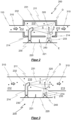
- FIG. 2 A schematic representation of a first exemplary embodiment of a scattered light detector 200 according to the invention can be found in Figure 2
- the scattered light detector 200 has a test area 210, which is delimited by a tubular or cylindrical test area wall 211.
- the test area 210 In order to form a flow path 310 through which a test fluid can flow, indicated by arrows, the test area 210 also has a flow inlet 212 and a flow outlet 213.
- the cross section of the flow path 310 formed within the test area 210 shown by dashed lines, corresponds approximately to the cross section of the flow inlet 212 and the flow outlet 213 or is formed by them.
- the flow inlet 212 can be connected to a pipe and/or hose system 110 of an intake fire detection system 100, the flow outlet 213 can be arranged directly in front of an intake device 130 of the intake fire detection system 100 (see Figure 1 ) or connected to the pipe and/or hose system 110.
- a light transmitter 230 in particular a light emitting diode and a light receiver 240, in particular a Photodiodes are each directly connected to the front of a circuit board 220 and optically separated from one another by an opaque separating device 221.
- the circuit board 220 and the active optical components connected to it, the light transmitter 230 and the light receiver 240, are arranged both outside the test area 210 and outside the test area wall 211.
- the test area wall 211 comprises two recesses 214.
- the light transmitter 230 and the light receiver 240 point orthogonally away from the circuit board 220 and are directed in the direction of the test area 210.
- a light beam 231 initially sent by the light transmitter 230 orthogonally to the front of the circuit board 220 is deflected by means of an optical waveguide 232 in order to run in an emission direction A directed along the flow path 310.
- the optical waveguide 232 assigned to the light transmitter 230 is arranged to pass through a recess 214 of the test area wall 211 and deflects the light beam 231 in an emission direction A, here parallel to the front of the circuit board 220.
- the light receiver 240 is also directed with its field of view towards the test area 210 in a receiving direction E that is orthogonal to the front of the circuit board 220, with the light beam 231 of the light transmitter 230 and the field of view of the light receiver 240 forming a second intersection volume, a so-called scattered light center.
- the scattered light center is placed within the flow path 310, thereby defining a third intersection volume, a detection volume D, in which the light beam 231 of the light transmitter 230, the field of view of the light receiver 240 and the flow path 310 of the test fluid overlap.
- a scattered light portion 233 scattered within the detection volume D can be detected by the light receiver 240.
- smoke particles 320 are contained within the overlap area X, which are sucked in from one or more monitoring rooms 300.
- a portion of the light beam 231 striking a smoke particle 320 is scattered in several directions, including at a scattering angle ⁇ .
- a direct scattered light path S is formed, ie a straight, non-reflected and non-deflected path of a scattered light portion 233 scattered in the overlapping area X on a smoke particle 320, which runs through a recess 214 in the test area wall 211 designed as a light passage or gap and hits the light receiver 240.
- the receiving direction E of the light receiver 240 is directed opposite to the scattered light path S.
- FIG. 3 A schematic representation of a second exemplary embodiment of a scattered light detector 200 according to the invention can be seen.
- the second embodiment of the scattered light detector 200 differs in that it has a test area wall 211 that delimits the test area 210 in a tube or cylinder shape and has a circular cylindrical cross-sectional area, the diameter of which corresponds to the diameter of the pipe and/or hose system 110.
- the test area wall 211 As an integral component of an intake fire detection system 100, it is advantageous to adapt the diameter of the circular cylindrical cross-sectional area to the diameter of the pipe and/or hose system 110, in particular to design it with an identical inner diameter.
- the test area wall 211 can then form an integral component of the pipe and/or hose system 100 as a so-called pipe fitting, or a line or flow section of the pipe and/or hose system 110, in particular of the supply pipe 113, can be used as the test area wall 211 for the scattered light detector 200.
- the flow inlet 212 and the flow outlet 213 are immediately flush with adjacent lines of the pipe and/or hose system 110 of the intake fire detection system 100.
- the flow path 310 is designed to run essentially within the entire test area 210. Due to the cylindrical geometry of the test area wall 211, corners and/or dead flow spaces within which contamination from particle deposits can easily occur can be avoided.
- the flow path 310 is preferably designed within the entire test area 210, whereby all particles 320 contained within the test fluid are captured by the flow and can thus be more easily transported out of the test area 210 via the flow outlet 213.
- a third exemplary embodiment of a scattered light detector 200 according to the invention is shown in Figure 4 shown schematically.
- the third embodiment of the scattered light detector 200 also has a test area wall 211 with a circular cylindrical cross-sectional area, which can be integrated into either a pipe and/or hose system 110 of an intake fire detection system 100 (see Figure 1 ) or even as an integral part of the pipe and/or hose system 110 (see Figure 3 ) can be formed.
- a flow path 310 is formed within the test area 210 and runs along the central axis of the cylindrical or circular-cylindrical cross-section test area wall 211.
- the light beam 231 sent by the light transmitter 230 is directed here at the flow path 310 and runs in a radiation direction A essentially radially or orthogonally to the flow path 310.
- the optical waveguide 232 which deflects the light beam 231 sent by the light transmitter 230, outside the test area 210 and outside the test area wall 211.
- all optical components, active as well as passive, are located outside the test area 210, which enables a trouble-free, low-turbulence test fluid flow along the flow path 310.
- a light trap 250 for absorbing a non-scattered portion of the light beam 231 emitted by the light transmitter 230 can expediently also be arranged within the test area 210.
- the light trap 250 is preferably designed as a complete or partial coating of the inner surface of the test area wall 211, but could alternatively also be arranged as an optical component within the test area 210.
- FIG. 5 A schematic representation of a fourth exemplary embodiment of a scattered light detector 200 according to the invention is shown.
- the scattered light detector 200 shown here differs in that the light beam 231 sent by the light transmitter 230 and directed radially onto the flow path 310 is focused by means of a first planar optic 261, in particular a converging lens or Fresnel lens.
- the first planar optic 261 is arranged within a recess 214 of the test area wall 211 and is connected to the optical waveguide 232, which deflects the light beam 231 sent by the light transmitter 230.
- the width of the light beam 231 is reduced by the first planar optic 261 and the light beam 231 itself is parallelized.
- an overlap area X between the flow path 310 of the test fluid and the light beam 231 is smaller than with a non-focused light beam, which enables more precise detection of the scattered scattered light.
- an optional light trap 250 can be designed with a correspondingly smaller size.
- the first planar optics 261 could also be designed as a simple window glass in order to only close the opening 214 so that the test fluid cannot escape through the recess 214.
- the direct scattered light path S which runs between the overlap area X or the detection volume D and the light receiver 240, is also focused by means of a second planar optic 262, in particular a converging lens or Fresnel lens.
- the scattered light component 233 incident on the second planar optic 262 is bundled and focused on the light receiver 240. In this way, it is possible to "intercept" and detect scattered light components that would otherwise run past the light receiver 240.
- the emission direction A of the light transmitter 230 in this embodiment does not run parallel to the front of the circuit board 220, so that the scattering angle ⁇ shown here as an example, at which the light beam 231 sent by the light transmitter 230 is scattered by a particle 320, is greater than 90°, which is why this can be referred to as so-called backward scattering ( ⁇ >90°).
- the second planar optic 262 is alternatively designed as a simple window glass.
- a schematic representation of a fifth exemplary embodiment of a scattered light detector 200 according to the invention with an indirect and focused scattered light path S can be found in the Figure 6 From the fourth embodiment described above (see Figure 5 ), the present fifth embodiment again differs in terms of the scattering angle ⁇ .
- the light beam 231 sent by the light transmitter 230 is scattered by a particle 320 at a scattering angle ⁇ of less than 90°, so that the present scattering can be classified in the area of forward scattering.
- the scattered light component 233 scattered at the scattering angle ⁇ runs along an indirect scattered light path S, i.e.
- the scattered light component 233 running along the scattered light path S is deflected by means of an optical waveguide 241 assigned to the light receiver 240 and arranged in its field of view, so that it has a "curved" course.
- the area of the circuit board 220 required to detect a scattered light component 233 scattered forwards at an angle between 0° and 90° can be reduced in this way.
- the deflection by means of the optical waveguide 241 makes it possible to detect forward scattering via a scattered light detector 200 with a single Printed circuit board 220, the front of which has both the light transmitter 230 and the light receiver 240.
- a second planar optic 262 is provided within the scattered light path S, which is arranged in a recess 214 of the test area wall 211 and in front of the optical waveguide 241 with respect to the direction of the scattered light path S.
- FIG 7 is a schematic representation of a sixth exemplary embodiment of a scattered light detector 200 according to the invention, which is provided for multi-detection.
- a light beam 231 sent by the light transmitter 230 is deflected by means of an optical waveguide 232 and directed onto the flow path 310 running within the test area 210, wherein the light beam 231 is focused by means of a first planar optic 261.
- the light beam 231 unlike in the fifth embodiment (see Figure 6 ), is deflected by an angle of approximately 90°, so that the light beam 231 runs essentially parallel to the front of the circuit board 220. Together with the flow path 310, the light beam 231 forms the overlap region X.
- further secondary light receivers 240a, 240b, 240c in this figure are each indirectly, ie via additional substructures or surface-mounted components 242a, 242b, 242c, also connected to the front of the circuit board 220.
- the surface-mounted components 242a, 242b, 242c are designed here as a solid support base, for example, whose support surface is pivoted by a respective detection angle ⁇ relative to the front of the circuit board 220 and is connected to the respectively assigned light auxiliary receiver 240a, 240b, 240c, so that the light auxiliary receivers 240a, 240b, 240c themselves are aligned for multi-detection in a respective detection angle ⁇ .
- the detection angle ⁇ spans between the front of the circuit board 220 and the respective reception direction E.
- the light auxiliary receivers 240a, 240b, 240c are each connected directly to the front of the circuit board 220, i.e.
- the respective detection angles ⁇ of the light receiver 240 and the secondary light receivers 240a, 240b, 240c are selected accordingly to form a common scattered light center with the light beam 231 within the overlap area X and thus to form a common detection volume D.
- a direct scattered light path S of a scattered light portion 233 scattered at an associated scattering angle ⁇ strikes the light receiver 240 or the secondary light receivers 240a, 240b, 240c (here shown schematically using the secondary light receiver 240c as an example).
- the scattering angle ⁇ -dependent scattered light distribution can be included in the evaluation, whereby, for example, fire and deceptive quantities (dust or vapor particles) can be distinguished.
- FIG. 8 A schematic representation of a seventh exemplary embodiment of a scattered light detector 200 according to the invention, which is intended for multi-detection, can be found in the Figure 8
- the light receiver 240 and the auxiliary light receivers 240a, 240b, 240c are aligned at a respective detection angle ⁇ to form a common detection volume D.
- the auxiliary light receivers 240a, 240b, 240c are each indirectly connected to the circuit board 220 via an associated surface-mounted component 242a, 242b, 242c, but here designed as an inclined sheet metal.
- polarization filters 243, 243a, 243b, 243c are also arranged within the respective direct and focused scattered light path S.
- the polarization planes of two polarization filters 243, 243a, 243b, 243c are orthogonal to each other, whereby additional analysis information can be obtained on the basis of the filtered scattered light component 233.
- FIG 9 is a schematic representation of an eighth exemplary embodiment of a scattered light detector 200 according to the invention, which is provided for multi-detection.
- the respective scattered light path S has a "curved" course or is indirectly
- a respective optical waveguide 241, 241a, 241b, 241c it is possible to change the detection angle ⁇ by deflecting the respective scattered light component 233, without using additional surface-mounted components 242a, 242b, 242c (see Figures 7 and 8 ), to change.
- the light secondary receivers 240a, 240b, 240c can thus also be connected directly, ie directly and without additional substructures, to the front of the circuit board 220.
- the distance between the light secondary receivers 240a, 240b, 240c and the light transmitter 230 required to detect the scattered light portion 233 scattered at the associated scattering angle ⁇ is smaller, so that the circuit board 220 can be designed with a smaller area in favor of an overall smaller scattered light detector 200.
- the size of the circuit board 220 and thus the size of the scattered light detector 200 can be reduced overall, so that multi-detection with several secondary light receivers 240a, 240b, 240c can be simplified or even implemented in the first place.
- all active optical components light transmitter 230, light receiver 240, light sub-receivers 240a, 240b, 240c
- additional manufacturing costs are saved and the structure of the scattered light detector 200 is considerably simplified.
- the Figure 10 an exemplary, schematic flow diagram of such a method can be taken.
- the method according to the invention is preferably carried out continuously for the constant monitoring of a monitoring space 300.
- the process sequence is explained step by step below using a single sampled test fluid quantity.
- a quantity of test fluid is first taken from one or more monitoring spaces 300 via one or more suction openings 120 of a suction fire detection system 100.
- the sampled quantity of test fluid is then fed to the scattered light detector 200 via a fluid-conducting pipe and/or hose system 110 (see also Figure 1 ).
- the scattered light detector 200 more precisely its test area 210, is integrated into the pipe and/or hose system 110 or is formed integrally with it, so that a flow path 310 is created along a flow section of the pipe and/or hose system 110, which then functions as a test area 210.
- An overlap area X is then formed within the test area 210 and consequently within the pipe and/or hose system 110 by a light transmitter 230 sending a light beam 231 in a beam direction A directed towards the flow path 310 or along the flow path 310.
- the light receiver 240 is directed towards the overlap area (X) to form a detection volume (D). If particles 320 are present within the aspirated test fluid quantity, a scattered light component 233 scattered by a particle 320 within the detection volume D is received by the light receiver 240 (see also, for example, Figure 2 ).
- the overlap area X within the pipe and/or hose system 110 of an intake fire detection system 100 in that both the light beam 231 sent by the light transmitter 230 and the flow path 310 carrying the test fluid meet within a flow section of the pipe and/or hose system 110 and at the same time the field of view of the light receiver 240 is directed towards them in a receiving direction E.
- the scattered light center is therefore also formed within a flow section of the pipe and/or hose system 110.
- a scattered light path 310 running between the overlap area X and the light receiver 240 can be formed directly or indirectly as required and/or as required. Further steps for evaluating the detected scattered light component for the presence of a fire or a fire hazard or the risk of a fire occurring are sufficiently known from the state of the art.
Landscapes
- Chemical & Material Sciences (AREA)
- Analytical Chemistry (AREA)
- Physics & Mathematics (AREA)
- General Physics & Mathematics (AREA)
- Business, Economics & Management (AREA)
- Emergency Management (AREA)
- Health & Medical Sciences (AREA)
- Life Sciences & Earth Sciences (AREA)
- Biochemistry (AREA)
- General Health & Medical Sciences (AREA)
- Immunology (AREA)
- Pathology (AREA)
- Fire-Detection Mechanisms (AREA)
- Investigating Or Analysing Materials By Optical Means (AREA)
Claims (13)
- Détecteur de lumière diffusée (200) destiné à détecter des particules, notamment des particules de fumée (320) dans un fluide de contrôle, destiné à être utilisé dans un système de détection d'incendie par aspiration (100), comprenant- une zone de contrôle (210), laquelle possède une entrée d'écoulement (212) et une sortie d'écoulement (213) en vue de former un trajet d'écoulement (310) qui peut être traversé par le fluide de contrôle,- un émetteur de lumière (230), lequel émet un faisceau lumineux (231) dans une direction de rayonnement (A), le faisceau lumineux (231) émis formant une zone d'intersection (X) avec le trajet d'écoulement (310),- un récepteur de lumière (240) destiné à recevoir une partie de lumière diffusée (233) diffusée dans la zone d'intersection (X) au niveau de particules (320),- une carte à circuit imprimé (220), l'émetteur de lumière (230) et le récepteur de lumière (240) étant reliés à un côté avant de la carte à circuit imprimé (220) qui est orienté vers la zone de contrôle (210) sous la forme de composants pouvant être montés en surface, et- le récepteur de lumière (240) est disposé de telle sorte qu'un trajet de lumière diffusée (S) direct ou indirect suit un tracé entre le récepteur de lumière (240) et la zone d'intersection (X),
caractérisé en ce que- la zone de contrôle (210) est délimitée par une paroi de zone de contrôle (211), la paroi de zone de contrôle (211) possédant un ou plusieurs évidements (214) destinés à recevoir des composants optiques et/ou à générer plusieurs passages de lumière,- l'émetteur de lumière (230) et le récepteur de lumière (240) ainsi que la carte à circuit imprimé (220) qui comporte l'émetteur de lumière (230) et le récepteur de lumière (240) étant disposés à l'extérieur de la paroi de zone de contrôle (211) qui délimite la zone de contrôle (210),- le faisceau lumineux (231) émis par l'émetteur de lumière (230) étant guidé dans la zone de contrôle (210) au moyen d'un guide d'ondes optiques (232) qui dévie le faisceau lumineux (231), le faisceau lumineux (231) pénétrant dans le milieu du guide d'ondes optiques (232) et étant transmis à l'intérieur de celui-ci,- le guide d'ondes optiques (232) débouchant à l'intérieur de l'un des évidements (214) de la paroi de zone de contrôle (211), étant accueilli par l'un des évidements (214) ou traversant l'un des évidements (214), et- un passage de lumière ou un composant optique non réfléchissant étant disposé à l'intérieur du trajet de lumière diffusée (S) direct qui suit un tracé entre le récepteur de lumière (240) et la zone d'intersection (X) et/ou- le trajet de lumière diffusée (S) indirect qui suit un tracé entre le récepteur de lumière (240) et la zone d'intersection (X) est formé au moyen d'un guide d'ondes optiques (232) disposé à l'intérieur de l'un des évidements (214) de la paroi de zone de contrôle (211) et dans le champ de vision du récepteur de lumière (240). - Détecteur de lumière diffusée (200) selon la revendication 1,
caractérisé en ce que
le faisceau lumineux (231) émis par l'émetteur de lumière (230) suit un tracé dans une direction de rayonnement (A) dirigée le long du trajet d'écoulement (310). - Détecteur de lumière diffusée (200) selon la revendication 1,
caractérisé en ce que
le faisceau lumineux (231) émis par l'émetteur de lumière (230) suit un tracé dans une direction de rayonnement (A) dirigée vers le trajet d'écoulement (310). - Détecteur de lumière diffusée (200) selon l'une des revendications 1 à 3,
caractérisé en ce que
le trajet de lumière diffusée (S) indirect qui suit un tracé entre le récepteur de lumière (240) et la zone d'intersection (X) est formé au moyen d'un guide d'ondes optiques (241) qui dévie la partie de lumière diffusée (233). - Détecteur de lumière diffusée (200) selon l'une des revendications précédentes,
caractérisé en ce que
une première optique plane (261) destinée à focaliser le faisceau lumineux (231) est disposée entre l'émetteur de lumière (230) et la zone d'intersection (X) et/ou une deuxième optique plane (262) destinée à focaliser une partie de lumière diffusée (233) diffusée le long du trajet de lumière diffusée (S) est disposée entre le récepteur de lumière (240) et la zone d'intersection (X). - Détecteur de lumière diffusée (200) selon l'une des revendications précédentes,
caractérisé en ce que
le guide d'ondes optiques (232, 241) et/ou la première optique plane (261) et/ou la deuxième optique plane (262) et/ou d'autres composants optiques sont disposés à l'extérieur de la zone de contrôle (210), en particulier à l'extérieur de la paroi de zone de contrôle (211) qui délimite la zone de contrôle (210). - Détecteur de lumière diffusée (200) selon l'une des revendications précédentes,
caractérisé en ce que
un passage de lumière ou un composant optique non réfléchissant est disposé à l'intérieur du trajet de lumière diffusée (S) direct qui suit un tracé entre le récepteur de lumière (240) et la zone d'intersection (X) ou le trajet de lumière diffusée (S) indirect qui suit un tracé entre le récepteur de lumière (240) et la zone d'intersection (X) est formé au moyen d'un guide d'ondes optiques (241) disposé à l'intérieur de l'un des évidements (214). - Détecteur de lumière diffusée (200) selon l'une des revendications précédentes,
caractérisé en ce que
un ou plusieurs récepteurs de lumière supplémentaires sont reliés en tant que récepteurs de lumière secondaires (240a, 240b, 240c) à la carte à circuit imprimé (220), notamment à un côté avant de la carte à circuit imprimé (220). - Détecteur de lumière diffusée (200) selon la revendication 8,
caractérisé en ce que
le ou les récepteurs de lumière secondaires (240a, 240b, 240c) sont disposés de telle sorte qu'un trajet de lumière diffusée (S) direct ou indirect suit un tracé entre le récepteur de lumière secondaire (240a, 240b, 240c) respectif et la zone d'intersection (X). - Détecteur de lumière diffusée (200) selon l'une des revendications 8 ou 9,
caractérisé en ce que
une ou plusieurs deuxièmes optiques planes (262) destinées à focaliser une partie de lumière diffusée (233) sont disposées dans un trajet de lumière diffusée (S) respectif entre les un ou plusieurs récepteurs de lumière secondaires (240a, 240b, 240c) et la zone d'intersection (X). - Système de détection d'incendie par aspiration (100) comprenant un détecteur de lumière diffusée (200) selon l'une des revendications 1 à 10, le système de détection d'incendie par aspiration (100) comprenant une ou plusieurs ouvertures d'aspiration (120) qui sont disposées dans un ou plusieurs espaces de surveillance (300) pour aspirer un fluide de contrôle, un système de tubes et/ou de tuyaux (110) destiné à la liaison fluidique de l'une ou des plusieurs ouvertures d'aspiration (120) avec le détecteur de lumière diffusée (200) et un dispositif d'aspiration (130) destiné à générer un écoulement et/ou une dépression à l'intérieur du système de tubes et/ou de tuyaux (110),
caractérisé en ce que
une zone de contrôle (210) du détecteur de lumière diffusée (230) est réalisée en tant que partie intégrante du système de tubes et/ou de tuyaux (110), par le fait que la zone de contrôle (210) est réalisée sous la forme d'une section d'écoulement du système de tubes et/ou de tuyaux (110). - Système de détection d'incendie par aspiration (100) selon la revendication 11,
caractérisé en ce que
une paroi de zone de contrôle (211) qui délimite la zone de contrôle (210) possède une entrée d'écoulement (212), laquelle est disposée avant la zone de contrôle (210) dans la direction d'écoulement (P) du fluide de contrôle afin de former et/ou d'orienter un trajet d'écoulement (310) à l'intérieur de la zone de contrôle (210) et possède une sortie d'écoulement (213) qui, dans la direction d'écoulement (P) du fluide de contrôle, est disposée après la zone de contrôle (210) et avant le dispositif d'aspiration (130). - Procédé de détection de particules contenues dans un fluide de contrôle, notamment de particules de fumée (320), en particulier pour la reconnaissance d'un incendie et/ou d'un début d'incendie, en utilisant un détecteur de lumière diffusée (200) selon l'une des revendications 1 à 10, lequel détecteur de lumière diffusée (200) possède un émetteur de lumière (230) destiné à former une zone d'intersection (X) avec le fluide de contrôle et un récepteur de lumière (240) destiné à détecter la lumière diffusée à l'intérieur de la zone d'intersection (X), un fluide de contrôle étant prélevé en continu au moyen d'une ou plusieurs ouvertures d'aspiration (120) dans une ou plusieurs chambres de contrôle (300) et étant acheminé au détecteur de lumière diffusée (200) au moyen d'un système de tubes et/ou de tuyaux (110) conduisant le fluide,
caractérisé en ce que
la zone d'intersection (X) est formée à l'intérieur du système de tubes et/ou de tuyaux (110) et le récepteur de lumière (240) est dirigé vers la zone d'intersection (X) en vue de former un volume de détection (D),- un trajet d'écoulement (310) qui guide le fluide de contrôle étant généré le long d'une portion d'écoulement du système de tubes et/ou de tuyaux (110), et- l'émetteur de lumière (230) émettant un faisceau lumineux (231) dans une direction de rayonnement (A) dirigée vers le trajet d'écoulement (310) ou le long du trajet d'écoulement (310), le faisceau lumineux (231) émis formant la zone d'intersection (X) avec le trajet d'écoulement (310).
Priority Applications (7)
| Application Number | Priority Date | Filing Date | Title |
|---|---|---|---|
| EP18020263.2A EP3584774B1 (fr) | 2018-06-19 | 2018-06-19 | Détecteur de lumière diffusée et système de détection d'incendie au niveau d'aspiration pourvu d'un détecteur de lumière diffusée |
| CN201980040755.5A CN112313720B (zh) | 2018-06-19 | 2019-06-12 | 散射光检测器和具有散射光检测器的吸气式火灾检测系统 |
| PCT/EP2019/065373 WO2019243135A1 (fr) | 2018-06-19 | 2019-06-12 | Détecteur de lumière dispersée et système de reconnaissance de feu d'aspiration avec un détecteur de lumière dispersée |
| AU2019290965A AU2019290965B2 (en) | 2018-06-19 | 2019-06-12 | Scattered light detector and aspirating fire detection system with a scattered light detector |
| MX2020013418A MX2020013418A (es) | 2018-06-19 | 2019-06-12 | Detector de luz dispersa y sistema de deteccion de incendios por succion con detector de luz dispersa. |
| US16/972,047 US11417187B2 (en) | 2018-06-19 | 2019-06-12 | Scattered light detector and suction fire detection system having a scattered light detector |
| CA3101697A CA3101697A1 (fr) | 2018-06-19 | 2019-06-12 | Detecteur de lumiere dispersee et systeme de reconnaissance de feu d'aspiration avec un detecteur de lumiere dispersee |
Applications Claiming Priority (1)
| Application Number | Priority Date | Filing Date | Title |
|---|---|---|---|
| EP18020263.2A EP3584774B1 (fr) | 2018-06-19 | 2018-06-19 | Détecteur de lumière diffusée et système de détection d'incendie au niveau d'aspiration pourvu d'un détecteur de lumière diffusée |
Publications (2)
| Publication Number | Publication Date |
|---|---|
| EP3584774A1 EP3584774A1 (fr) | 2019-12-25 |
| EP3584774B1 true EP3584774B1 (fr) | 2025-03-05 |
Family
ID=62712707
Family Applications (1)
| Application Number | Title | Priority Date | Filing Date |
|---|---|---|---|
| EP18020263.2A Active EP3584774B1 (fr) | 2018-06-19 | 2018-06-19 | Détecteur de lumière diffusée et système de détection d'incendie au niveau d'aspiration pourvu d'un détecteur de lumière diffusée |
Country Status (7)
| Country | Link |
|---|---|
| US (1) | US11417187B2 (fr) |
| EP (1) | EP3584774B1 (fr) |
| CN (1) | CN112313720B (fr) |
| AU (1) | AU2019290965B2 (fr) |
| CA (1) | CA3101697A1 (fr) |
| MX (1) | MX2020013418A (fr) |
| WO (1) | WO2019243135A1 (fr) |
Families Citing this family (6)
| Publication number | Priority date | Publication date | Assignee | Title |
|---|---|---|---|---|
| EP3955226B1 (fr) * | 2020-08-12 | 2025-02-19 | Wagner Group GmbH | Système de détection des particules d'admission pourvu de système de guidage de lumière |
| US11385212B2 (en) * | 2020-09-25 | 2022-07-12 | Honeywell International Inc. | Smoke detection sample point |
| US11804118B2 (en) * | 2022-03-01 | 2023-10-31 | Honeywell International Inc. | Aspirating smoke detector discreet sample point |
| CN115862256B (zh) * | 2022-11-22 | 2024-12-13 | 中国联合网络通信集团有限公司 | 一种光电感烟探测器以及光电感烟探测器自维保系统 |
| CN115858403B (zh) * | 2023-03-01 | 2023-06-02 | 中国电子科技集团公司第十研究所 | 一种电子系统的虚警率预计方法 |
| EP4530685A1 (fr) | 2023-09-28 | 2025-04-02 | Wagner Group GmbH | Prisme optique et unité de détection de particules comprenant un prisme optique |
Citations (2)
| Publication number | Priority date | Publication date | Assignee | Title |
|---|---|---|---|---|
| JP4981404B2 (ja) * | 2006-10-16 | 2012-07-18 | ニッタン株式会社 | 粒子カウンタ式煙感知装置 |
| EP3029647B1 (fr) * | 2014-12-04 | 2017-05-31 | Siemens Schweiz AG | Détecteur de fumée à écran diffusant ouvert, notamment équipé d'une LED Side-looker |
Family Cites Families (24)
| Publication number | Priority date | Publication date | Assignee | Title |
|---|---|---|---|---|
| GB1179409A (en) * | 1966-11-28 | 1970-01-28 | Kidde Walter Co Ltd | Improvements in or relating to Smoke Detectors |
| DE3233368A1 (de) * | 1982-09-08 | 1984-03-08 | Heimann Gmbh, 6200 Wiesbaden | Strahlungsrauchmelder |
| GB9014015D0 (en) * | 1990-06-23 | 1990-08-15 | Dennis Peter N J | Improvements in or relating to smoke detectors |
| JPH08233736A (ja) | 1995-02-27 | 1996-09-13 | Nohmi Bosai Ltd | 微粒子検出センサ |
| JP3588535B2 (ja) * | 1997-06-30 | 2004-11-10 | ホーチキ株式会社 | 煙感知装置 |
| WO1999045369A1 (fr) * | 1998-03-07 | 1999-09-10 | Robert Bosch Gmbh | Capteur optique |
| JP2001014570A (ja) * | 1999-04-28 | 2001-01-19 | Nittan Co Ltd | 火災感知器 |
| DE10124280A1 (de) * | 2001-05-23 | 2002-12-12 | Preussag Ag Minimax | Selbstansaugende Brandmeldeeinrichtung |
| US6842243B2 (en) * | 2001-12-10 | 2005-01-11 | Apprise Technologies, Inc. | Turbidity sensor |
| CN2599569Y (zh) * | 2003-01-17 | 2004-01-14 | 海湾安全技术股份有限公司 | 立式双向散射型光电感烟探测器 |
| DE102004004098B3 (de) * | 2004-01-27 | 2005-09-01 | Wagner Alarm- Und Sicherungssysteme Gmbh | Verfahren zur Auswertung eines Streulichtsignals und Streulichtdetektor zur Durchführung des Verfahrens |
| DE102007045018B4 (de) * | 2007-09-20 | 2011-02-17 | Perkinelmer Optoelectronics Gmbh & Co.Kg | Strahlungsleitvorrichtung für einen Detektor, Streustrahlungsdetektor |
| ATE507544T1 (de) * | 2008-02-19 | 2011-05-15 | Siemens Ag | Rauchdetektion mittels zweier spektral unterschiedlicher streulichtmessungen |
| JP2009237697A (ja) * | 2008-03-26 | 2009-10-15 | Nohmi Bosai Ltd | 光電式煙感知器 |
| FR2964743B1 (fr) | 2010-09-14 | 2015-06-26 | Finsecur | Circuit de detection de fumee, detecteur de fumee le comportant et dispositif d'alarme les comportant. |
| CN103098107B (zh) * | 2011-09-02 | 2016-05-25 | 日本芬翁股份有限公司 | 吸气式烟雾检测系统 |
| EP2608174B1 (fr) * | 2011-12-20 | 2016-10-19 | Siemens Schweiz AG | Procédé de reconnaissance d'un objet parasite dans un volume de diffusion d'un détecteur d'incendie optique et détecteur d'incendie optique |
| PL2881719T3 (pl) | 2013-12-03 | 2024-08-12 | Atexon Oy | Wykrywanie iskier |
| EP3029646B1 (fr) * | 2014-12-01 | 2019-01-30 | Siemens Schweiz AG | Détecteur de fumée à écran diffusant doté d'une diode lumineuse bicolore |
| FR3030750B1 (fr) | 2014-12-22 | 2017-01-13 | Finsecur | Detecteur optique d'une valeur d'une grandeur physique de l'atmosphere representative d'un danger |
| US9196141B1 (en) * | 2015-05-15 | 2015-11-24 | Google, Inc. | Smoke detector chamber |
| RU2687141C1 (ru) * | 2015-08-25 | 2019-05-07 | Фенвал Контролз Оф Джэпэн, Лтд. | Фотоэлектрический датчик дыма |
| CN107016815A (zh) * | 2016-01-28 | 2017-08-04 | 日本德赖化学股份有限公司 | 光电式烟雾传感器 |
| CN107545695A (zh) * | 2016-06-27 | 2018-01-05 | 北京西门子西伯乐斯电子有限公司 | 烟感探测器 |
-
2018
- 2018-06-19 EP EP18020263.2A patent/EP3584774B1/fr active Active
-
2019
- 2019-06-12 CA CA3101697A patent/CA3101697A1/fr active Pending
- 2019-06-12 AU AU2019290965A patent/AU2019290965B2/en active Active
- 2019-06-12 MX MX2020013418A patent/MX2020013418A/es unknown
- 2019-06-12 CN CN201980040755.5A patent/CN112313720B/zh active Active
- 2019-06-12 WO PCT/EP2019/065373 patent/WO2019243135A1/fr not_active Ceased
- 2019-06-12 US US16/972,047 patent/US11417187B2/en active Active
Patent Citations (2)
| Publication number | Priority date | Publication date | Assignee | Title |
|---|---|---|---|---|
| JP4981404B2 (ja) * | 2006-10-16 | 2012-07-18 | ニッタン株式会社 | 粒子カウンタ式煙感知装置 |
| EP3029647B1 (fr) * | 2014-12-04 | 2017-05-31 | Siemens Schweiz AG | Détecteur de fumée à écran diffusant ouvert, notamment équipé d'une LED Side-looker |
Also Published As
| Publication number | Publication date |
|---|---|
| AU2019290965B2 (en) | 2024-08-29 |
| US11417187B2 (en) | 2022-08-16 |
| AU2019290965A1 (en) | 2020-12-17 |
| CA3101697A1 (fr) | 2019-12-26 |
| MX2020013418A (es) | 2021-02-26 |
| US20210174659A1 (en) | 2021-06-10 |
| CN112313720B (zh) | 2023-06-16 |
| WO2019243135A1 (fr) | 2019-12-26 |
| EP3584774A1 (fr) | 2019-12-25 |
| CN112313720A (zh) | 2021-02-02 |
Similar Documents
| Publication | Publication Date | Title |
|---|---|---|
| EP3584774B1 (fr) | Détecteur de lumière diffusée et système de détection d'incendie au niveau d'aspiration pourvu d'un détecteur de lumière diffusée | |
| EP3274975B1 (fr) | Détecteur d'incendie présentant un dispositif de lumière diffusée au niveau d'une ouverture d'entrée de fumée en vue de la surveillance de l'encrassement | |
| EP0756703B1 (fr) | Dispositif de mesure de la dispersion de la lumiere par des particules | |
| DE102012007561A1 (de) | Gasdetektorsystem | |
| DE2504300B2 (de) | Vorrichtung zur Messung des Absorptionsvermögens eines Mediums, insbesondere von Rauch | |
| RU2006108798A (ru) | Оптический расходомер для измерения расхода газов и жидкостей в трубопроводах | |
| EP0120881A1 (fr) | Detecteur de fumee a rayonnement diffuse. | |
| DE69319184T2 (de) | Flüssigkeitsverschmutzungfühler | |
| DE102016113492A1 (de) | Teilchensensor | |
| DE4444079C2 (de) | Verfahren und Vorrichtung zur Durchführung dieses Verfahrens zum Messen der Lage einer Kante von einer Bahn oder einem Bogen | |
| CN109632588B (zh) | 一种油液颗粒物污染检测装置和方法 | |
| EP0802499A2 (fr) | Balayeur à luminescence | |
| DE7935901U1 (de) | Strahlungsdetektor | |
| EP2963627B1 (fr) | Agencement destiné à atténuer la lumière incidente d'un faisceau de rayons | |
| EP2093731A1 (fr) | Détecteur de fumée optique linéaire doté de plusieurs rayons partiels | |
| CN117233056B (zh) | 生物气溶胶空气动力学谱仪 | |
| EP1903352B1 (fr) | Capteur optoélectronique et procédé d'opération d'un capteur optoélectronique | |
| DE102007013356A1 (de) | Partikelsensor für strömende flüssige oder gasförmige Medien | |
| EP1010992B1 (fr) | Système optique | |
| DE2339575A1 (de) | Lichtschranken- und lichttastersystem zur herstellung verschiedenartiger lichtschranken- und lichttaster-bauformen unterschiedlicher optischer lichtstrahlenfuehrung | |
| EP4530685A1 (fr) | Prisme optique et unité de détection de particules comprenant un prisme optique | |
| DE10202999B4 (de) | Verfahren und Vorrichtung zum Messen der Größenverteilung und Konzentration von Partikeln in einem Fluid | |
| RU2814440C2 (ru) | Детектор рассеянного света и аспирационная система обнаружения пожара с детектором рассеянного света | |
| DE10060044C2 (de) | Streulichtdetektor | |
| DE2758517A1 (de) | Rauchdetektor mit einer dunkelfeldoptik |
Legal Events
| Date | Code | Title | Description |
|---|---|---|---|
| STAA | Information on the status of an ep patent application or granted ep patent |
Free format text: STATUS: UNKNOWN |
|
| PUAI | Public reference made under article 153(3) epc to a published international application that has entered the european phase |
Free format text: ORIGINAL CODE: 0009012 |
|
| STAA | Information on the status of an ep patent application or granted ep patent |
Free format text: STATUS: THE APPLICATION HAS BEEN PUBLISHED |
|
| AK | Designated contracting states |
Kind code of ref document: A1 Designated state(s): AL AT BE BG CH CY CZ DE DK EE ES FI FR GB GR HR HU IE IS IT LI LT LU LV MC MK MT NL NO PL PT RO RS SE SI SK SM TR |
|
| AX | Request for extension of the european patent |
Extension state: BA ME |
|
| STAA | Information on the status of an ep patent application or granted ep patent |
Free format text: STATUS: REQUEST FOR EXAMINATION WAS MADE |
|
| 17P | Request for examination filed |
Effective date: 20200604 |
|
| RBV | Designated contracting states (corrected) |
Designated state(s): AL AT BE BG CH CY CZ DE DK EE ES FI FR GB GR HR HU IE IS IT LI LT LU LV MC MK MT NL NO PL PT RO RS SE SI SK SM TR |
|
| STAA | Information on the status of an ep patent application or granted ep patent |
Free format text: STATUS: EXAMINATION IS IN PROGRESS |
|
| 17Q | First examination report despatched |
Effective date: 20211126 |
|
| P01 | Opt-out of the competence of the unified patent court (upc) registered |
Effective date: 20230526 |
|
| GRAP | Despatch of communication of intention to grant a patent |
Free format text: ORIGINAL CODE: EPIDOSNIGR1 |
|
| STAA | Information on the status of an ep patent application or granted ep patent |
Free format text: STATUS: GRANT OF PATENT IS INTENDED |
|
| INTG | Intention to grant announced |
Effective date: 20241218 |
|
| GRAS | Grant fee paid |
Free format text: ORIGINAL CODE: EPIDOSNIGR3 |
|
| GRAA | (expected) grant |
Free format text: ORIGINAL CODE: 0009210 |
|
| STAA | Information on the status of an ep patent application or granted ep patent |
Free format text: STATUS: THE PATENT HAS BEEN GRANTED |
|
| AK | Designated contracting states |
Kind code of ref document: B1 Designated state(s): AL AT BE BG CH CY CZ DE DK EE ES FI FR GB GR HR HU IE IS IT LI LT LU LV MC MK MT NL NO PL PT RO RS SE SI SK SM TR |
|
| REG | Reference to a national code |
Ref country code: GB Ref legal event code: FG4D Free format text: NOT ENGLISH |
|
| REG | Reference to a national code |
Ref country code: CH Ref legal event code: EP |
|
| REG | Reference to a national code |
Ref country code: DE Ref legal event code: R096 Ref document number: 502018015615 Country of ref document: DE |
|
| REG | Reference to a national code |
Ref country code: IE Ref legal event code: FG4D Free format text: LANGUAGE OF EP DOCUMENT: GERMAN |
|
| PG25 | Lapsed in a contracting state [announced via postgrant information from national office to epo] |
Ref country code: RS Free format text: LAPSE BECAUSE OF FAILURE TO SUBMIT A TRANSLATION OF THE DESCRIPTION OR TO PAY THE FEE WITHIN THE PRESCRIBED TIME-LIMIT Effective date: 20250605 |
|
| PG25 | Lapsed in a contracting state [announced via postgrant information from national office to epo] |
Ref country code: FI Free format text: LAPSE BECAUSE OF FAILURE TO SUBMIT A TRANSLATION OF THE DESCRIPTION OR TO PAY THE FEE WITHIN THE PRESCRIBED TIME-LIMIT Effective date: 20250305 |
|
| PGFP | Annual fee paid to national office [announced via postgrant information from national office to epo] |
Ref country code: DE Payment date: 20250618 Year of fee payment: 8 |
|
| REG | Reference to a national code |
Ref country code: NL Ref legal event code: MP Effective date: 20250305 |
|
| PG25 | Lapsed in a contracting state [announced via postgrant information from national office to epo] |
Ref country code: ES Free format text: LAPSE BECAUSE OF FAILURE TO SUBMIT A TRANSLATION OF THE DESCRIPTION OR TO PAY THE FEE WITHIN THE PRESCRIBED TIME-LIMIT Effective date: 20250305 |
|
| PGFP | Annual fee paid to national office [announced via postgrant information from national office to epo] |
Ref country code: GB Payment date: 20250618 Year of fee payment: 8 |
|
| REG | Reference to a national code |
Ref country code: LT Ref legal event code: MG9D |
|
| PG25 | Lapsed in a contracting state [announced via postgrant information from national office to epo] |
Ref country code: NO Free format text: LAPSE BECAUSE OF FAILURE TO SUBMIT A TRANSLATION OF THE DESCRIPTION OR TO PAY THE FEE WITHIN THE PRESCRIBED TIME-LIMIT Effective date: 20250605 |
|
| PG25 | Lapsed in a contracting state [announced via postgrant information from national office to epo] |
Ref country code: HR Free format text: LAPSE BECAUSE OF FAILURE TO SUBMIT A TRANSLATION OF THE DESCRIPTION OR TO PAY THE FEE WITHIN THE PRESCRIBED TIME-LIMIT Effective date: 20250305 |
|
| PG25 | Lapsed in a contracting state [announced via postgrant information from national office to epo] |
Ref country code: LV Free format text: LAPSE BECAUSE OF FAILURE TO SUBMIT A TRANSLATION OF THE DESCRIPTION OR TO PAY THE FEE WITHIN THE PRESCRIBED TIME-LIMIT Effective date: 20250305 |
|
| PGFP | Annual fee paid to national office [announced via postgrant information from national office to epo] |
Ref country code: FR Payment date: 20250626 Year of fee payment: 8 |
|
| PG25 | Lapsed in a contracting state [announced via postgrant information from national office to epo] |
Ref country code: GR Free format text: LAPSE BECAUSE OF FAILURE TO SUBMIT A TRANSLATION OF THE DESCRIPTION OR TO PAY THE FEE WITHIN THE PRESCRIBED TIME-LIMIT Effective date: 20250606 Ref country code: BG Free format text: LAPSE BECAUSE OF FAILURE TO SUBMIT A TRANSLATION OF THE DESCRIPTION OR TO PAY THE FEE WITHIN THE PRESCRIBED TIME-LIMIT Effective date: 20250305 |
|
| PGFP | Annual fee paid to national office [announced via postgrant information from national office to epo] |
Ref country code: AT Payment date: 20250620 Year of fee payment: 8 |
|
| PG25 | Lapsed in a contracting state [announced via postgrant information from national office to epo] |
Ref country code: NL Free format text: LAPSE BECAUSE OF FAILURE TO SUBMIT A TRANSLATION OF THE DESCRIPTION OR TO PAY THE FEE WITHIN THE PRESCRIBED TIME-LIMIT Effective date: 20250305 |
|
| PG25 | Lapsed in a contracting state [announced via postgrant information from national office to epo] |
Ref country code: SE Free format text: LAPSE BECAUSE OF FAILURE TO SUBMIT A TRANSLATION OF THE DESCRIPTION OR TO PAY THE FEE WITHIN THE PRESCRIBED TIME-LIMIT Effective date: 20250305 |
|
| PG25 | Lapsed in a contracting state [announced via postgrant information from national office to epo] |
Ref country code: SM Free format text: LAPSE BECAUSE OF FAILURE TO SUBMIT A TRANSLATION OF THE DESCRIPTION OR TO PAY THE FEE WITHIN THE PRESCRIBED TIME-LIMIT Effective date: 20250305 |
|
| PG25 | Lapsed in a contracting state [announced via postgrant information from national office to epo] |
Ref country code: PT Free format text: LAPSE BECAUSE OF FAILURE TO SUBMIT A TRANSLATION OF THE DESCRIPTION OR TO PAY THE FEE WITHIN THE PRESCRIBED TIME-LIMIT Effective date: 20250707 |
|
| PG25 | Lapsed in a contracting state [announced via postgrant information from national office to epo] |
Ref country code: PL Free format text: LAPSE BECAUSE OF FAILURE TO SUBMIT A TRANSLATION OF THE DESCRIPTION OR TO PAY THE FEE WITHIN THE PRESCRIBED TIME-LIMIT Effective date: 20250305 |
|
| PGFP | Annual fee paid to national office [announced via postgrant information from national office to epo] |
Ref country code: IT Payment date: 20250627 Year of fee payment: 8 |
|
| PGFP | Annual fee paid to national office [announced via postgrant information from national office to epo] |
Ref country code: CH Payment date: 20250701 Year of fee payment: 8 |
|
| PG25 | Lapsed in a contracting state [announced via postgrant information from national office to epo] |
Ref country code: CZ Free format text: LAPSE BECAUSE OF FAILURE TO SUBMIT A TRANSLATION OF THE DESCRIPTION OR TO PAY THE FEE WITHIN THE PRESCRIBED TIME-LIMIT Effective date: 20250305 Ref country code: EE Free format text: LAPSE BECAUSE OF FAILURE TO SUBMIT A TRANSLATION OF THE DESCRIPTION OR TO PAY THE FEE WITHIN THE PRESCRIBED TIME-LIMIT Effective date: 20250305 |
|
| PG25 | Lapsed in a contracting state [announced via postgrant information from national office to epo] |
Ref country code: RO Free format text: LAPSE BECAUSE OF FAILURE TO SUBMIT A TRANSLATION OF THE DESCRIPTION OR TO PAY THE FEE WITHIN THE PRESCRIBED TIME-LIMIT Effective date: 20250305 |
|
| PG25 | Lapsed in a contracting state [announced via postgrant information from national office to epo] |
Ref country code: SK Free format text: LAPSE BECAUSE OF FAILURE TO SUBMIT A TRANSLATION OF THE DESCRIPTION OR TO PAY THE FEE WITHIN THE PRESCRIBED TIME-LIMIT Effective date: 20250305 |
|
| PG25 | Lapsed in a contracting state [announced via postgrant information from national office to epo] |
Ref country code: IS Free format text: LAPSE BECAUSE OF FAILURE TO SUBMIT A TRANSLATION OF THE DESCRIPTION OR TO PAY THE FEE WITHIN THE PRESCRIBED TIME-LIMIT Effective date: 20250705 |
|
| REG | Reference to a national code |
Ref country code: DE Ref legal event code: R097 Ref document number: 502018015615 Country of ref document: DE |
|
| PLBE | No opposition filed within time limit |
Free format text: ORIGINAL CODE: 0009261 |
|
| STAA | Information on the status of an ep patent application or granted ep patent |
Free format text: STATUS: NO OPPOSITION FILED WITHIN TIME LIMIT |
|
| PG25 | Lapsed in a contracting state [announced via postgrant information from national office to epo] |
Ref country code: DK Free format text: LAPSE BECAUSE OF FAILURE TO SUBMIT A TRANSLATION OF THE DESCRIPTION OR TO PAY THE FEE WITHIN THE PRESCRIBED TIME-LIMIT Effective date: 20250305 |
|
| REG | Reference to a national code |
Ref country code: CH Ref legal event code: L10 Free format text: ST27 STATUS EVENT CODE: U-0-0-L10-L00 (AS PROVIDED BY THE NATIONAL OFFICE) Effective date: 20260114 |
|
| PG25 | Lapsed in a contracting state [announced via postgrant information from national office to epo] |
Ref country code: MC Free format text: LAPSE BECAUSE OF FAILURE TO SUBMIT A TRANSLATION OF THE DESCRIPTION OR TO PAY THE FEE WITHIN THE PRESCRIBED TIME-LIMIT Effective date: 20250305 |
|
| 26N | No opposition filed |
Effective date: 20251208 |
|
| PG25 | Lapsed in a contracting state [announced via postgrant information from national office to epo] |
Ref country code: LU Free format text: LAPSE BECAUSE OF NON-PAYMENT OF DUE FEES Effective date: 20250619 |
|
| REG | Reference to a national code |
Ref country code: BE Ref legal event code: MM Effective date: 20250630 |
|
| PG25 | Lapsed in a contracting state [announced via postgrant information from national office to epo] |
Ref country code: IE Free format text: LAPSE BECAUSE OF NON-PAYMENT OF DUE FEES Effective date: 20250619 |
|
| PG25 | Lapsed in a contracting state [announced via postgrant information from national office to epo] |
Ref country code: BE Free format text: LAPSE BECAUSE OF NON-PAYMENT OF DUE FEES Effective date: 20250630 |