EP3584916A1 - Procédé de commande d'inverseur - Google Patents
Procédé de commande d'inverseur Download PDFInfo
- Publication number
- EP3584916A1 EP3584916A1 EP19162262.0A EP19162262A EP3584916A1 EP 3584916 A1 EP3584916 A1 EP 3584916A1 EP 19162262 A EP19162262 A EP 19162262A EP 3584916 A1 EP3584916 A1 EP 3584916A1
- Authority
- EP
- European Patent Office
- Prior art keywords
- voltage
- direct current
- value
- control unit
- link
- Prior art date
- Legal status (The legal status is an assumption and is not a legal conclusion. Google has not performed a legal analysis and makes no representation as to the accuracy of the status listed.)
- Granted
Links
Images


Classifications
-
- H—ELECTRICITY
- H02—GENERATION; CONVERSION OR DISTRIBUTION OF ELECTRIC POWER
- H02M—APPARATUS FOR CONVERSION BETWEEN AC AND AC, BETWEEN AC AND DC, OR BETWEEN DC AND DC, AND FOR USE WITH MAINS OR SIMILAR POWER SUPPLY SYSTEMS; CONVERSION OF DC OR AC INPUT POWER INTO SURGE OUTPUT POWER; CONTROL OR REGULATION THEREOF
- H02M1/00—Details of apparatus for conversion
- H02M1/32—Means for protecting converters other than automatic disconnection
-
- H—ELECTRICITY
- H02—GENERATION; CONVERSION OR DISTRIBUTION OF ELECTRIC POWER
- H02H—EMERGENCY PROTECTIVE CIRCUIT ARRANGEMENTS
- H02H3/00—Emergency protective circuit arrangements for automatic disconnection directly responsive to an undesired change from normal electric working condition with or without subsequent reconnection ; integrated protection
- H02H3/02—Details
- H02H3/06—Details with automatic reconnection
- H02H3/066—Reconnection being a consequence of eliminating the fault which caused disconnection
-
- H—ELECTRICITY
- H02—GENERATION; CONVERSION OR DISTRIBUTION OF ELECTRIC POWER
- H02H—EMERGENCY PROTECTIVE CIRCUIT ARRANGEMENTS
- H02H7/00—Emergency protective circuit arrangements specially adapted for specific types of electric machines or apparatus or for sectionalised protection of cable or line systems, and effecting automatic switching in the event of an undesired change from normal working conditions
- H02H7/10—Emergency protective circuit arrangements specially adapted for specific types of electric machines or apparatus or for sectionalised protection of cable or line systems, and effecting automatic switching in the event of an undesired change from normal working conditions for converters; for rectifiers
- H02H7/12—Emergency protective circuit arrangements specially adapted for specific types of electric machines or apparatus or for sectionalised protection of cable or line systems, and effecting automatic switching in the event of an undesired change from normal working conditions for converters; for rectifiers for static converters or rectifiers
- H02H7/122—Emergency protective circuit arrangements specially adapted for specific types of electric machines or apparatus or for sectionalised protection of cable or line systems, and effecting automatic switching in the event of an undesired change from normal working conditions for converters; for rectifiers for static converters or rectifiers for inverters, i.e. DC/AC converters
- H02H7/1222—Emergency protective circuit arrangements specially adapted for specific types of electric machines or apparatus or for sectionalised protection of cable or line systems, and effecting automatic switching in the event of an undesired change from normal working conditions for converters; for rectifiers for static converters or rectifiers for inverters, i.e. DC/AC converters responsive to abnormalities in the input circuit, e.g. transients in the DC input
-
- H—ELECTRICITY
- H02—GENERATION; CONVERSION OR DISTRIBUTION OF ELECTRIC POWER
- H02H—EMERGENCY PROTECTIVE CIRCUIT ARRANGEMENTS
- H02H9/00—Emergency protective circuit arrangements for limiting excess current or voltage without disconnection
- H02H9/04—Emergency protective circuit arrangements for limiting excess current or voltage without disconnection responsive to excess voltage
- H02H9/045—Emergency protective circuit arrangements for limiting excess current or voltage without disconnection responsive to excess voltage adapted to a particular application and not provided for elsewhere
-
- H—ELECTRICITY
- H02—GENERATION; CONVERSION OR DISTRIBUTION OF ELECTRIC POWER
- H02M—APPARATUS FOR CONVERSION BETWEEN AC AND AC, BETWEEN AC AND DC, OR BETWEEN DC AND DC, AND FOR USE WITH MAINS OR SIMILAR POWER SUPPLY SYSTEMS; CONVERSION OF DC OR AC INPUT POWER INTO SURGE OUTPUT POWER; CONTROL OR REGULATION THEREOF
- H02M5/00—Conversion of AC power input into AC power output, e.g. for change of voltage, for change of frequency, for change of number of phases
- H02M5/40—Conversion of AC power input into AC power output, e.g. for change of voltage, for change of frequency, for change of number of phases with intermediate conversion into DC
- H02M5/42—Conversion of AC power input into AC power output, e.g. for change of voltage, for change of frequency, for change of number of phases with intermediate conversion into DC by static converters
- H02M5/44—Conversion of AC power input into AC power output, e.g. for change of voltage, for change of frequency, for change of number of phases with intermediate conversion into DC by static converters using discharge tubes or semiconductor devices to convert the intermediate DC into AC
- H02M5/453—Conversion of AC power input into AC power output, e.g. for change of voltage, for change of frequency, for change of number of phases with intermediate conversion into DC by static converters using discharge tubes or semiconductor devices to convert the intermediate DC into AC using devices of a triode or transistor type requiring continuous application of a control signal
- H02M5/458—Conversion of AC power input into AC power output, e.g. for change of voltage, for change of frequency, for change of number of phases with intermediate conversion into DC by static converters using discharge tubes or semiconductor devices to convert the intermediate DC into AC using devices of a triode or transistor type requiring continuous application of a control signal using semiconductor devices only
-
- H—ELECTRICITY
- H02—GENERATION; CONVERSION OR DISTRIBUTION OF ELECTRIC POWER
- H02M—APPARATUS FOR CONVERSION BETWEEN AC AND AC, BETWEEN AC AND DC, OR BETWEEN DC AND DC, AND FOR USE WITH MAINS OR SIMILAR POWER SUPPLY SYSTEMS; CONVERSION OF DC OR AC INPUT POWER INTO SURGE OUTPUT POWER; CONTROL OR REGULATION THEREOF
- H02M7/00—Conversion of AC power input into DC power output; Conversion of DC power input into AC power output
- H02M7/42—Conversion of DC power input into AC power output without possibility of reversal
- H02M7/44—Conversion of DC power input into AC power output without possibility of reversal by static converters
- H02M7/48—Conversion of DC power input into AC power output without possibility of reversal by static converters using discharge tubes with control electrode or semiconductor devices with control electrode
- H02M7/53—Conversion of DC power input into AC power output without possibility of reversal by static converters using discharge tubes with control electrode or semiconductor devices with control electrode using devices of a triode or transistor type requiring continuous application of a control signal
- H02M7/537—Conversion of DC power input into AC power output without possibility of reversal by static converters using discharge tubes with control electrode or semiconductor devices with control electrode using devices of a triode or transistor type requiring continuous application of a control signal using semiconductor devices only, e.g. single switched pulse inverters
- H02M7/5387—Conversion of DC power input into AC power output without possibility of reversal by static converters using discharge tubes with control electrode or semiconductor devices with control electrode using devices of a triode or transistor type requiring continuous application of a control signal using semiconductor devices only, e.g. single switched pulse inverters in a bridge configuration
- H02M7/53871—Conversion of DC power input into AC power output without possibility of reversal by static converters using discharge tubes with control electrode or semiconductor devices with control electrode using devices of a triode or transistor type requiring continuous application of a control signal using semiconductor devices only, e.g. single switched pulse inverters in a bridge configuration with automatic control of output voltage or current
-
- H—ELECTRICITY
- H02—GENERATION; CONVERSION OR DISTRIBUTION OF ELECTRIC POWER
- H02P—CONTROL OR REGULATION OF ELECTRIC MOTORS, ELECTRIC GENERATORS OR DYNAMO-ELECTRIC CONVERTERS; CONTROLLING TRANSFORMERS, REACTORS OR CHOKE COILS
- H02P29/00—Arrangements for regulating or controlling electric motors, appropriate for both AC and DC motors
- H02P29/02—Providing protection against overload without automatic interruption of supply
- H02P29/024—Detecting a fault condition, e.g. short circuit, locked rotor, open circuit or loss of load
- H02P29/0241—Detecting a fault condition, e.g. short circuit, locked rotor, open circuit or loss of load the fault being an overvoltage
-
- H—ELECTRICITY
- H02—GENERATION; CONVERSION OR DISTRIBUTION OF ELECTRIC POWER
- H02H—EMERGENCY PROTECTIVE CIRCUIT ARRANGEMENTS
- H02H3/00—Emergency protective circuit arrangements for automatic disconnection directly responsive to an undesired change from normal electric working condition with or without subsequent reconnection ; integrated protection
- H02H3/02—Details
- H02H3/027—Details with automatic disconnection after a predetermined time
-
- H—ELECTRICITY
- H02—GENERATION; CONVERSION OR DISTRIBUTION OF ELECTRIC POWER
- H02M—APPARATUS FOR CONVERSION BETWEEN AC AND AC, BETWEEN AC AND DC, OR BETWEEN DC AND DC, AND FOR USE WITH MAINS OR SIMILAR POWER SUPPLY SYSTEMS; CONVERSION OF DC OR AC INPUT POWER INTO SURGE OUTPUT POWER; CONTROL OR REGULATION THEREOF
- H02M1/00—Details of apparatus for conversion
- H02M1/0003—Details of control, feedback or regulation circuits
- H02M1/0016—Control circuits providing compensation of output voltage deviations using feedforward of disturbance parameters
- H02M1/0022—Control circuits providing compensation of output voltage deviations using feedforward of disturbance parameters the disturbance parameters being input voltage fluctuations
Definitions
- the present disclosure relates to a method for controlling an inverter.
- An inverter is an inverse-converting device that electrically convert direct current (DC) to alternating current (AC).
- the inverter used in the industry receives a power supplied from a commercial power supply, varies a voltage and frequency thereof on its own, and supplies the varied voltage and frequency to a motor.
- the inverter is defined as a series of devices that control the motor velocity to be used with high efficiency.
- the inverter may be controlled by a variable voltage variable frequency (VVVF) scheme.
- VVVF variable voltage variable frequency
- the inverter may vary the voltage and frequency input to the motor based on pulse width modulation (PWM) output.
- PWM pulse width modulation
- Figure 1 shows a typical inverter configuration.
- an inverter 100 receives an alternating current power of three phases and a rectifier 110 rectifies the alternating current power.
- a direct current-link capacitor 120 may smooth and store a direct current voltage rectified by the rectifier 110.
- An inverting unit 130 converts the direct current voltage stored in the direct current-link capacitor 120 based on the PWM control signal. Thus, the inverting unit outputs an alternating current voltage having a predefined voltage and frequency and may provide the same to the motor.
- the inverting unit 130 includes three legs. In each leg, two switching elements are connected in series.
- the direct current-link voltage rarely exceeds the rated voltage of the direct current-link capacitor 120.
- a fluctuation of the input voltage is large.
- the direct current-link voltage exceeds the rated voltage of the direct current-link capacitor 120, thereby causing the direct current-link overvoltage fault and thus causing the inverter 100 to stop.
- a technical purpose to be achieved by the present disclosure is to provide a method for controlling an inverter in which when an input voltage becomes high, increasing an operable region of the inverter allows the inverte to continuously operate.
- a technical purpose to be achieved by the present disclosure is to provide a method for controlling an inverter, in which the method may satisfy a lifespan condition of a direct current-link capacitor without requiring a hardware change.
- a method for controlling an inverter in an inverter system including the inverter, wherein the inverter includes a direct current-link capacitor, and an inverting unit including a plurality of switching elements, wherein the inverter system includes a control unit for controlling the inverting unit, wherein the method comprises: checking, by the control unit, whether a direct current-link voltage of the direct current-link capacitor is equal to or greater than a predefined first voltage; checking, by the control unit, whether the direct current-link voltage is greater than or equal to a second voltage greater than the first voltage; when the direct current-link voltage is greater than or equal to the first voltage and is smaller than the second voltage, calculating, by the control unit, a value using the direct current-link voltage and a time, and accumulating, by the control unit, the calculated value over time to generate a cumulative value; when the cumulative value is greater than or equal to a predefined first value, blocking, by the control unit, an output of the inverting unit;
- the method further comprises, when the direct current-link voltage is greater than or equal to the second voltage, blocking the output of the inverting unit by the control unit.
- the value calculated using the direct current-link voltage and the time is V 2 t, where V indicates the direct current-link voltage, and t indicates a unit time.
- the method further comprises, after updating the cumulative value as the obtained value and when the updated cumulative value is smaller than 0, updating the cumulative value to 0 by the control unit.
- the method further comprises, when a predefined time period has elapsed after the output of the inverting unit is blocked, when the direct current-link voltage is within a rated voltage range, disabling, by the control unit, the blocking of the output of the inverting unit.
- the direct current-link capacitor may be protected from a problem occurring when the overvoltage state of the direct current-link capacitor is maintained since the input voltage fluctuation of the inverter is large, or a voltage from the motor is regenerated. Further, a situation that frequent overvoltage faults when the input voltage is high disallow the continuous operation of the inverter may be avoided.
- Figure 2 illustrates an example of a time it will take for an overvoltage fault to occur based on a direct current-link voltage.
- the time required for the occurrence of the overvoltage fault is about 1 msec.
- the direct current-link voltage is 820V, the time it takes for an overvoltage fault to occur is about 400 msec.
- the larger the direct current-link voltage the shorter the time required for an overvoltage fault to occur.
- a method for controlling an inverter may be configured such that an inverse time characteristic is present in the specification guaranteed by the IEC 60383 4-14 standard, in order to protect the capacitor 20.
- the inverter is disabled for 5 seconds after an overvoltage fault occurs in the inverter.
- the direct current-link capacitor voltage is within the rated voltage of the capacitor 20 after 5 seconds after the overvoltage occurs, the fault is released, such that the inverter 1 is enabled.
- the method calculates V 2 t, and calculates a cumulative value of V 2 t.
- the cumulative value of V 2 t is greater than or equal to a predetermined reference value ⁇
- the method generates an overvoltage fault signal.
- V 2 t is continuously accumulated.
- the cumulative value may be reduced by a predetermined value ⁇ .
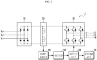
- Figure 3 is a block diagram of an inverter system including an inverter control device according to an embodiment of the present disclosure.
- the inverter 1 in accordance with one embodiment of the present disclosure includes a rectifier 10, a direct current-link capacitor 20, and an inverting unit 30.
- the inverter system may include the inverter 1, a power supply 40, an isolator 50, and a control unit 60.
- the inverter control device may include a power supply 40, an isolator 50, and a control unit 60.
- the rectifier 10 may rectify an input three-phase power.
- the direct current-link capacitor 20 may smooth and store the power.
- the direct current-link capacitor 20 may be composed of a series connection between two or more capacitors.
- the inverting unit 30 includes a plurality of semiconductor switching elements. The voltage stored in the direct current-link capacitor 20 may be converted to a three-phase alternating current voltage via on/off operations of upper and lower switching elements of the three-phase legs.
- the power supply 40 may be, for example, a switched mode power supply (SMPS).
- SMPS switched mode power supply
- the voltage detected in the direct current-link capacitor 20 may be provided to the power supply 40.
- the power supply 40 may divide the direct current-link voltage input into a small voltage. For example, when a direct current-link voltage 900V is input to the power supply 40, the power supply 40 may convert the voltage to 200 mV and provide the same to the isolator 50.
- SMPS switched mode power supply
- the isolator 50 may provide the control unit 60 with the small voltage which results from a division of the direct current-link voltage from the power supply 40.
- the isolator 50 may be a passive element that transfers a signal in a single direction of a circuit.
- the control unit 60 determines the overvoltage state of the direct current-link voltage and blocks a gate signal of the inverting unit 30 based on the determination result to perform the overvoltage protection.
- a method for controlling an inverter according to an embodiment of the present disclosure will be described with reference to the drawings.
- the inverter control device further includes a storage unit 70.
- the storage unit may store data generated by the control unit 60.
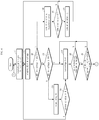
- Figure 4 is a flow chart illustrating a method for controlling an inverter according to an embodiment of the present disclosure.
- the control unit 60 applies a gate signal to switching elements of the inverting unit 30 (S10).
- S10 switching elements of the inverting unit 30
- the control unit 60 applies a gate signal so that the on/off of the switching elements of the inverting unit 30 may be controlled.
- the power supply 40 may receive the direct current-link voltage of the direct current-link capacitor 20 from a voltage detector (not shown). The power supply then converts the DC-link voltage to a small voltage. Then, the converted small voltage may be provided to the control unit 60 through the isolator 50.
- the control unit 60 checks the direct current-link voltage.
- the control unit may check whether the direct current-link voltage is greater than or equal to a predefined first voltage (assuming 805 V in one embodiment of the present disclosure).
- a predefined first voltage assuming 805 V in one embodiment of the present disclosure.
- the capacitance of each of the series-connected capacitors of the direct current-link capacitor 20 is 400V.
- the first voltage may be 800V in principle.
- the first voltage is assumed to be 805 V, with taking into account a margin. It should be understood, however, that this is merely one embodiment of the present disclosure and the disclosure is not limited thereto.
- the magnitude of the first voltage may be determined based on the number of capacitors connected in series and the capacitance of the individual capacitors.
- a direct current-link voltage and a comparator reference are compared with each other. It is determined whether overvoltage has occurred based on the comparison result. Based on this determination, the gate signal of the inverting unit 30 is interrupted. That is, when the comparator reference is set to, for example, 820 V, and when the direct current-link voltage exceeds 820V, it is determined that overvoltage occurred. Therefore, when the voltage fluctuation is large, or the voltage is regenerated, such that the overvoltage state of the direct current-link capacitor is maintained, there was a problem that frequent overvoltage fault occurred.
- the present disclosure aims to solve the problem.
- the control unit 60 may determine whether the direct current-link voltage is greater than or equal to a predefined second voltage (e.g., 850 V in one embodiment of the present disclosure).
- a predefined second voltage e.g., 850 V in one embodiment of the present disclosure.
- the second voltage is not limited to 850V. The second voltage may be determined based on the number of capacitors connected in series and the capacitance of the individual capacitors.
- control unit 60 determines that the current state is an overvoltage fault. Then, the control unit may block the gate signal to be transmitted to the inverting unit 30 and thus block the output of the inverting unit 30.
- V 2 t may be accumulated S30.
- V indicates a direct current-link voltage
- t indicates a preset unit time.
- the cumulative value may be stored in the storage unit 70.
- the control unit 60 determines the current state to be an overvoltage fault. Thus, the control unit 60 may block the gate signal transmitted to the inverting unit 30 to block the output of the inverting unit 30. However, when the cumulative value of V 2 t is not equal to or larger than the predefined value ⁇ , the method proceeds to S15, where the control unit 60 may recheck the direct current-link voltage.
- the control unit 60 determines whether a predefined time period (for example, 5 seconds) has elapsed after the output of the inverting unit 30 is blocked. When the predefined time period has not elapsed, the control unit may maintain the interruption state of the output of the inverting unit 30.
- a predefined time period for example, 5 seconds
- the control unit 60 checks whether the direct current-link voltage is within the rated voltage range. When the DC link voltage is within the range of the rated voltage, the method proceeds again to S10, where the control unit 60 transmits a gate signal to the switching elements of the inverting unit 30, such that the operation of the inverter 1 may be started. However, when the direct current-link voltage is out of the range of the rated voltage, the control unit may maintain the output blocking state of the inverting unit 30.
- the control unit 60 may calculate a value obtained by subtracting ⁇ from the cumulative value and update the calculated value to be the cumulative value S45.
- V 2 t may be accumulated during a time period other than 5 seconds.
- control unit 60 When the updated cumulative value of the control unit 60 is smaller than 0 S50, the control unit updates the cumulative value to be 0 S55. The method proceeds again to S15 where the control unit may check the direct current-link voltage.
- the direct current-link capacitor may be protected from a problem occurring when the overvoltage state of the direct current-link capacitor is maintained since the input voltage fluctuation of the inverter is large, or a voltage from the motor is regenerated. Further, a situation that frequent overvoltage faults when the input voltage is high disallow the continuous operation of the inverter may be avoided.
Landscapes
- Engineering & Computer Science (AREA)
- Power Engineering (AREA)
- Inverter Devices (AREA)
Applications Claiming Priority (1)
| Application Number | Priority Date | Filing Date | Title |
|---|---|---|---|
| KR1020180069669A KR20190142562A (ko) | 2018-06-18 | 2018-06-18 | 인버터 제어방법 |
Publications (2)
| Publication Number | Publication Date |
|---|---|
| EP3584916A1 true EP3584916A1 (fr) | 2019-12-25 |
| EP3584916B1 EP3584916B1 (fr) | 2023-07-12 |
Family
ID=65801889
Family Applications (1)
| Application Number | Title | Priority Date | Filing Date |
|---|---|---|---|
| EP19162262.0A Active EP3584916B1 (fr) | 2018-06-18 | 2019-03-12 | Procédé de commande d'inverseur |
Country Status (5)
| Country | Link |
|---|---|
| US (1) | US10333429B1 (fr) |
| EP (1) | EP3584916B1 (fr) |
| JP (1) | JP6630424B2 (fr) |
| KR (1) | KR20190142562A (fr) |
| CN (1) | CN110620518A (fr) |
Citations (4)
| Publication number | Priority date | Publication date | Assignee | Title |
|---|---|---|---|---|
| JPH06335154A (ja) * | 1993-05-21 | 1994-12-02 | Toshiba Corp | 欠相検知装置 |
| JP2007166815A (ja) * | 2005-12-15 | 2007-06-28 | Toshiba Mitsubishi-Electric Industrial System Corp | インバータ装置及びその過電圧保護方法 |
| EP2434628A2 (fr) * | 2010-09-27 | 2012-03-28 | Fuji Electric Co., Ltd. | Procédé de protection de surtension pour un dispositif inverseur |
| WO2015097838A1 (fr) * | 2013-12-27 | 2015-07-02 | 株式会社日立産機システム | Dispositif de conversion de puissance |
Family Cites Families (9)
| Publication number | Priority date | Publication date | Assignee | Title |
|---|---|---|---|---|
| JP4077326B2 (ja) * | 2003-01-21 | 2008-04-16 | 三菱電機株式会社 | インバータ装置の回生電力の処理方法およびこの方法に使用するインバータ装置 |
| KR100977013B1 (ko) | 2003-10-24 | 2010-08-19 | 엘지전자 주식회사 | 모터의 과전압 보호회로 |
| JP4980686B2 (ja) * | 2006-10-06 | 2012-07-18 | トヨタ自動車株式会社 | 電力システムおよびこれを備える駆動装置並びにこれを搭載する車両、電力システムの制御方法 |
| JP2009095202A (ja) * | 2007-10-12 | 2009-04-30 | Daikin Ind Ltd | インバータ |
| JP5520639B2 (ja) * | 2010-03-05 | 2014-06-11 | 株式会社日立産機システム | 電力変換装置および過負荷保護方法 |
| JP5363607B2 (ja) * | 2012-04-05 | 2013-12-11 | ファナック株式会社 | Dcリンク低電圧アラーム検出レベル可変機能を有するモータ駆動装置 |
| JP5638043B2 (ja) * | 2012-09-07 | 2014-12-10 | ファナック株式会社 | アラームレベル設定部を有するモータ駆動装置 |
| JP5820021B1 (ja) * | 2014-06-13 | 2015-11-24 | ファナック株式会社 | 充電抵抗の保護手段を有するモータ制御装置 |
| JP6287661B2 (ja) | 2014-07-22 | 2018-03-07 | アイシン・エィ・ダブリュ株式会社 | 回転電機制御装置 |
-
2018
- 2018-06-18 KR KR1020180069669A patent/KR20190142562A/ko not_active Ceased
- 2018-11-29 JP JP2018224116A patent/JP6630424B2/ja not_active Expired - Fee Related
- 2018-12-03 CN CN201811466793.0A patent/CN110620518A/zh active Pending
- 2018-12-05 US US16/210,206 patent/US10333429B1/en active Active
-
2019
- 2019-03-12 EP EP19162262.0A patent/EP3584916B1/fr active Active
Patent Citations (4)
| Publication number | Priority date | Publication date | Assignee | Title |
|---|---|---|---|---|
| JPH06335154A (ja) * | 1993-05-21 | 1994-12-02 | Toshiba Corp | 欠相検知装置 |
| JP2007166815A (ja) * | 2005-12-15 | 2007-06-28 | Toshiba Mitsubishi-Electric Industrial System Corp | インバータ装置及びその過電圧保護方法 |
| EP2434628A2 (fr) * | 2010-09-27 | 2012-03-28 | Fuji Electric Co., Ltd. | Procédé de protection de surtension pour un dispositif inverseur |
| WO2015097838A1 (fr) * | 2013-12-27 | 2015-07-02 | 株式会社日立産機システム | Dispositif de conversion de puissance |
Also Published As
| Publication number | Publication date |
|---|---|
| JP2019221123A (ja) | 2019-12-26 |
| KR20190142562A (ko) | 2019-12-27 |
| CN110620518A (zh) | 2019-12-27 |
| JP6630424B2 (ja) | 2020-01-15 |
| US10333429B1 (en) | 2019-06-25 |
| EP3584916B1 (fr) | 2023-07-12 |
Similar Documents
| Publication | Publication Date | Title |
|---|---|---|
| TWI392213B (zh) | Power supply | |
| US6118676A (en) | Dynamic voltage sag correction | |
| JP6730515B2 (ja) | 電力変換装置 | |
| US8154890B2 (en) | Inverter apparatus with control and voltage-sag circuitry to quickly restart when recovering from a mini power failure | |
| US10790698B2 (en) | Uninterruptible power supply system and uninterruptible power supply | |
| US9197139B2 (en) | Rectifier charge rate controller | |
| CN112840522B (zh) | 电源装置以及交流电源的异常检测方法 | |
| US20160327998A1 (en) | Low Capacitance Drive With Improved Immunity | |
| US9525363B2 (en) | Method for voltage dip compensation of inverter | |
| US10250037B2 (en) | Harmonic current compensator and air-conditioning system | |
| US10042007B2 (en) | Method for detecting a failing rectifier or rectifier source | |
| EP3244521B1 (fr) | Système de conversion de puissance ayant une régulation de bus cc pour maintenir l'alimentation en cas d'état de réseau anormal | |
| KR20200106205A (ko) | 전원 장치 | |
| KR101653374B1 (ko) | 리액터 보호 모듈이 내장된 자동 역률 보상 장치 | |
| EP3584916A1 (fr) | Procédé de commande d'inverseur | |
| JP7370954B2 (ja) | 電力変換装置 | |
| US20220239146A1 (en) | Power supply device | |
| US20110110131A1 (en) | Method And Apparatus For A Power Conversion Device | |
| KR20150005822A (ko) | H-브리지 멀티 레벨 인버터의 순간정전 제어 장치 및 방법 | |
| JP3773798B2 (ja) | 電力変換装置 | |
| CN112534695B (zh) | 控制mmc的方法 | |
| KR102777642B1 (ko) | 인버터의 출력 개폐 또는 결상 상황에서의 보호 동작 방법 및 이를 이용하는 인버터 | |
| JP7844761B1 (ja) | 無停電電源装置 | |
| JP2020156146A (ja) | 電力変換装置 | |
| KR102485120B1 (ko) | 인버터 직류링크 캐패시터의 전압분배 회로 |
Legal Events
| Date | Code | Title | Description |
|---|---|---|---|
| PUAI | Public reference made under article 153(3) epc to a published international application that has entered the european phase |
Free format text: ORIGINAL CODE: 0009012 |
|
| STAA | Information on the status of an ep patent application or granted ep patent |
Free format text: STATUS: THE APPLICATION HAS BEEN PUBLISHED |
|
| AK | Designated contracting states |
Kind code of ref document: A1 Designated state(s): AL AT BE BG CH CY CZ DE DK EE ES FI FR GB GR HR HU IE IS IT LI LT LU LV MC MK MT NL NO PL PT RO RS SE SI SK SM TR |
|
| AX | Request for extension of the european patent |
Extension state: BA ME |
|
| STAA | Information on the status of an ep patent application or granted ep patent |
Free format text: STATUS: REQUEST FOR EXAMINATION WAS MADE |
|
| 17P | Request for examination filed |
Effective date: 20200623 |
|
| RBV | Designated contracting states (corrected) |
Designated state(s): AL AT BE BG CH CY CZ DE DK EE ES FI FR GB GR HR HU IE IS IT LI LT LU LV MC MK MT NL NO PL PT RO RS SE SI SK SM TR |
|
| STAA | Information on the status of an ep patent application or granted ep patent |
Free format text: STATUS: EXAMINATION IS IN PROGRESS |
|
| 17Q | First examination report despatched |
Effective date: 20211110 |
|
| REG | Reference to a national code |
Ref country code: DE Ref legal event code: R079 Ipc: H02M0005458000 Ref country code: DE Ref legal event code: R079 Ref document number: 602019032401 Country of ref document: DE Free format text: PREVIOUS MAIN CLASS: H02M0001320000 Ipc: H02M0005458000 |
|
| GRAP | Despatch of communication of intention to grant a patent |
Free format text: ORIGINAL CODE: EPIDOSNIGR1 |
|
| STAA | Information on the status of an ep patent application or granted ep patent |
Free format text: STATUS: GRANT OF PATENT IS INTENDED |
|
| RIC1 | Information provided on ipc code assigned before grant |
Ipc: H02M 1/32 20070101ALI20230210BHEP Ipc: H02P 29/024 20160101ALI20230210BHEP Ipc: H02H 7/122 20060101ALI20230210BHEP Ipc: H02H 3/027 20060101ALI20230210BHEP Ipc: H02M 7/5387 20060101ALI20230210BHEP Ipc: H02M 5/458 20060101AFI20230210BHEP |
|
| INTG | Intention to grant announced |
Effective date: 20230321 |
|
| GRAS | Grant fee paid |
Free format text: ORIGINAL CODE: EPIDOSNIGR3 |
|
| GRAA | (expected) grant |
Free format text: ORIGINAL CODE: 0009210 |
|
| STAA | Information on the status of an ep patent application or granted ep patent |
Free format text: STATUS: THE PATENT HAS BEEN GRANTED |
|
| AK | Designated contracting states |
Kind code of ref document: B1 Designated state(s): AL AT BE BG CH CY CZ DE DK EE ES FI FR GB GR HR HU IE IS IT LI LT LU LV MC MK MT NL NO PL PT RO RS SE SI SK SM TR |
|
| REG | Reference to a national code |
Ref country code: CH Ref legal event code: EP |
|
| REG | Reference to a national code |
Ref country code: DE Ref legal event code: R096 Ref document number: 602019032401 Country of ref document: DE |
|
| REG | Reference to a national code |
Ref country code: IE Ref legal event code: FG4D |
|
| REG | Reference to a national code |
Ref country code: LT Ref legal event code: MG9D |
|
| REG | Reference to a national code |
Ref country code: NL Ref legal event code: MP Effective date: 20230712 |
|
| REG | Reference to a national code |
Ref country code: AT Ref legal event code: MK05 Ref document number: 1588161 Country of ref document: AT Kind code of ref document: T Effective date: 20230712 |
|
| PG25 | Lapsed in a contracting state [announced via postgrant information from national office to epo] |
Ref country code: NL Free format text: LAPSE BECAUSE OF FAILURE TO SUBMIT A TRANSLATION OF THE DESCRIPTION OR TO PAY THE FEE WITHIN THE PRESCRIBED TIME-LIMIT Effective date: 20230712 |
|
| PG25 | Lapsed in a contracting state [announced via postgrant information from national office to epo] |
Ref country code: GR Free format text: LAPSE BECAUSE OF FAILURE TO SUBMIT A TRANSLATION OF THE DESCRIPTION OR TO PAY THE FEE WITHIN THE PRESCRIBED TIME-LIMIT Effective date: 20231013 |
|
| PG25 | Lapsed in a contracting state [announced via postgrant information from national office to epo] |
Ref country code: ES Free format text: LAPSE BECAUSE OF FAILURE TO SUBMIT A TRANSLATION OF THE DESCRIPTION OR TO PAY THE FEE WITHIN THE PRESCRIBED TIME-LIMIT Effective date: 20230712 |
|
| PG25 | Lapsed in a contracting state [announced via postgrant information from national office to epo] |
Ref country code: IS Free format text: LAPSE BECAUSE OF FAILURE TO SUBMIT A TRANSLATION OF THE DESCRIPTION OR TO PAY THE FEE WITHIN THE PRESCRIBED TIME-LIMIT Effective date: 20231112 |
|
| PG25 | Lapsed in a contracting state [announced via postgrant information from national office to epo] |
Ref country code: SE Free format text: LAPSE BECAUSE OF FAILURE TO SUBMIT A TRANSLATION OF THE DESCRIPTION OR TO PAY THE FEE WITHIN THE PRESCRIBED TIME-LIMIT Effective date: 20230712 Ref country code: RS Free format text: LAPSE BECAUSE OF FAILURE TO SUBMIT A TRANSLATION OF THE DESCRIPTION OR TO PAY THE FEE WITHIN THE PRESCRIBED TIME-LIMIT Effective date: 20230712 Ref country code: PT Free format text: LAPSE BECAUSE OF FAILURE TO SUBMIT A TRANSLATION OF THE DESCRIPTION OR TO PAY THE FEE WITHIN THE PRESCRIBED TIME-LIMIT Effective date: 20231113 Ref country code: NO Free format text: LAPSE BECAUSE OF FAILURE TO SUBMIT A TRANSLATION OF THE DESCRIPTION OR TO PAY THE FEE WITHIN THE PRESCRIBED TIME-LIMIT Effective date: 20231012 Ref country code: LV Free format text: LAPSE BECAUSE OF FAILURE TO SUBMIT A TRANSLATION OF THE DESCRIPTION OR TO PAY THE FEE WITHIN THE PRESCRIBED TIME-LIMIT Effective date: 20230712 Ref country code: LT Free format text: LAPSE BECAUSE OF FAILURE TO SUBMIT A TRANSLATION OF THE DESCRIPTION OR TO PAY THE FEE WITHIN THE PRESCRIBED TIME-LIMIT Effective date: 20230712 Ref country code: IS Free format text: LAPSE BECAUSE OF FAILURE TO SUBMIT A TRANSLATION OF THE DESCRIPTION OR TO PAY THE FEE WITHIN THE PRESCRIBED TIME-LIMIT Effective date: 20231112 Ref country code: HR Free format text: LAPSE BECAUSE OF FAILURE TO SUBMIT A TRANSLATION OF THE DESCRIPTION OR TO PAY THE FEE WITHIN THE PRESCRIBED TIME-LIMIT Effective date: 20230712 Ref country code: GR Free format text: LAPSE BECAUSE OF FAILURE TO SUBMIT A TRANSLATION OF THE DESCRIPTION OR TO PAY THE FEE WITHIN THE PRESCRIBED TIME-LIMIT Effective date: 20231013 Ref country code: FI Free format text: LAPSE BECAUSE OF FAILURE TO SUBMIT A TRANSLATION OF THE DESCRIPTION OR TO PAY THE FEE WITHIN THE PRESCRIBED TIME-LIMIT Effective date: 20230712 Ref country code: ES Free format text: LAPSE BECAUSE OF FAILURE TO SUBMIT A TRANSLATION OF THE DESCRIPTION OR TO PAY THE FEE WITHIN THE PRESCRIBED TIME-LIMIT Effective date: 20230712 Ref country code: AT Free format text: LAPSE BECAUSE OF FAILURE TO SUBMIT A TRANSLATION OF THE DESCRIPTION OR TO PAY THE FEE WITHIN THE PRESCRIBED TIME-LIMIT Effective date: 20230712 |
|
| PG25 | Lapsed in a contracting state [announced via postgrant information from national office to epo] |
Ref country code: PL Free format text: LAPSE BECAUSE OF FAILURE TO SUBMIT A TRANSLATION OF THE DESCRIPTION OR TO PAY THE FEE WITHIN THE PRESCRIBED TIME-LIMIT Effective date: 20230712 |
|
| REG | Reference to a national code |
Ref country code: DE Ref legal event code: R097 Ref document number: 602019032401 Country of ref document: DE |
|
| PG25 | Lapsed in a contracting state [announced via postgrant information from national office to epo] |
Ref country code: SM Free format text: LAPSE BECAUSE OF FAILURE TO SUBMIT A TRANSLATION OF THE DESCRIPTION OR TO PAY THE FEE WITHIN THE PRESCRIBED TIME-LIMIT Effective date: 20230712 Ref country code: RO Free format text: LAPSE BECAUSE OF FAILURE TO SUBMIT A TRANSLATION OF THE DESCRIPTION OR TO PAY THE FEE WITHIN THE PRESCRIBED TIME-LIMIT Effective date: 20230712 Ref country code: EE Free format text: LAPSE BECAUSE OF FAILURE TO SUBMIT A TRANSLATION OF THE DESCRIPTION OR TO PAY THE FEE WITHIN THE PRESCRIBED TIME-LIMIT Effective date: 20230712 Ref country code: DK Free format text: LAPSE BECAUSE OF FAILURE TO SUBMIT A TRANSLATION OF THE DESCRIPTION OR TO PAY THE FEE WITHIN THE PRESCRIBED TIME-LIMIT Effective date: 20230712 Ref country code: CZ Free format text: LAPSE BECAUSE OF FAILURE TO SUBMIT A TRANSLATION OF THE DESCRIPTION OR TO PAY THE FEE WITHIN THE PRESCRIBED TIME-LIMIT Effective date: 20230712 Ref country code: SK Free format text: LAPSE BECAUSE OF FAILURE TO SUBMIT A TRANSLATION OF THE DESCRIPTION OR TO PAY THE FEE WITHIN THE PRESCRIBED TIME-LIMIT Effective date: 20230712 |
|
| PLBE | No opposition filed within time limit |
Free format text: ORIGINAL CODE: 0009261 |
|
| STAA | Information on the status of an ep patent application or granted ep patent |
Free format text: STATUS: NO OPPOSITION FILED WITHIN TIME LIMIT |
|
| PG25 | Lapsed in a contracting state [announced via postgrant information from national office to epo] |
Ref country code: IT Free format text: LAPSE BECAUSE OF FAILURE TO SUBMIT A TRANSLATION OF THE DESCRIPTION OR TO PAY THE FEE WITHIN THE PRESCRIBED TIME-LIMIT Effective date: 20230712 |
|
| 26N | No opposition filed |
Effective date: 20240415 |
|
| PG25 | Lapsed in a contracting state [announced via postgrant information from national office to epo] |
Ref country code: SI Free format text: LAPSE BECAUSE OF FAILURE TO SUBMIT A TRANSLATION OF THE DESCRIPTION OR TO PAY THE FEE WITHIN THE PRESCRIBED TIME-LIMIT Effective date: 20230712 |
|
| REG | Reference to a national code |
Ref country code: CH Ref legal event code: PL |
|
| PG25 | Lapsed in a contracting state [announced via postgrant information from national office to epo] |
Ref country code: BG Free format text: LAPSE BECAUSE OF FAILURE TO SUBMIT A TRANSLATION OF THE DESCRIPTION OR TO PAY THE FEE WITHIN THE PRESCRIBED TIME-LIMIT Effective date: 20230712 |
|
| PG25 | Lapsed in a contracting state [announced via postgrant information from national office to epo] |
Ref country code: LU Free format text: LAPSE BECAUSE OF NON-PAYMENT OF DUE FEES Effective date: 20240312 |
|
| PG25 | Lapsed in a contracting state [announced via postgrant information from national office to epo] |
Ref country code: MC Free format text: LAPSE BECAUSE OF FAILURE TO SUBMIT A TRANSLATION OF THE DESCRIPTION OR TO PAY THE FEE WITHIN THE PRESCRIBED TIME-LIMIT Effective date: 20230712 |
|
| GBPC | Gb: european patent ceased through non-payment of renewal fee |
Effective date: 20240312 |
|
| PG25 | Lapsed in a contracting state [announced via postgrant information from national office to epo] |
Ref country code: MC Free format text: LAPSE BECAUSE OF FAILURE TO SUBMIT A TRANSLATION OF THE DESCRIPTION OR TO PAY THE FEE WITHIN THE PRESCRIBED TIME-LIMIT Effective date: 20230712 Ref country code: LU Free format text: LAPSE BECAUSE OF NON-PAYMENT OF DUE FEES Effective date: 20240312 Ref country code: BG Free format text: LAPSE BECAUSE OF FAILURE TO SUBMIT A TRANSLATION OF THE DESCRIPTION OR TO PAY THE FEE WITHIN THE PRESCRIBED TIME-LIMIT Effective date: 20230712 |
|
| REG | Reference to a national code |
Ref country code: BE Ref legal event code: MM Effective date: 20240331 |
|
| PG25 | Lapsed in a contracting state [announced via postgrant information from national office to epo] |
Ref country code: BE Free format text: LAPSE BECAUSE OF NON-PAYMENT OF DUE FEES Effective date: 20240331 |
|
| PG25 | Lapsed in a contracting state [announced via postgrant information from national office to epo] |
Ref country code: GB Free format text: LAPSE BECAUSE OF NON-PAYMENT OF DUE FEES Effective date: 20240312 |
|
| PG25 | Lapsed in a contracting state [announced via postgrant information from national office to epo] |
Ref country code: FR Free format text: LAPSE BECAUSE OF NON-PAYMENT OF DUE FEES Effective date: 20240331 |
|
| PG25 | Lapsed in a contracting state [announced via postgrant information from national office to epo] |
Ref country code: IE Free format text: LAPSE BECAUSE OF NON-PAYMENT OF DUE FEES Effective date: 20240312 |
|
| PG25 | Lapsed in a contracting state [announced via postgrant information from national office to epo] |
Ref country code: IE Free format text: LAPSE BECAUSE OF NON-PAYMENT OF DUE FEES Effective date: 20240312 Ref country code: GB Free format text: LAPSE BECAUSE OF NON-PAYMENT OF DUE FEES Effective date: 20240312 Ref country code: FR Free format text: LAPSE BECAUSE OF NON-PAYMENT OF DUE FEES Effective date: 20240331 Ref country code: BE Free format text: LAPSE BECAUSE OF NON-PAYMENT OF DUE FEES Effective date: 20240331 Ref country code: CH Free format text: LAPSE BECAUSE OF NON-PAYMENT OF DUE FEES Effective date: 20240331 |
|
| PG25 | Lapsed in a contracting state [announced via postgrant information from national office to epo] |
Ref country code: CY Free format text: LAPSE BECAUSE OF FAILURE TO SUBMIT A TRANSLATION OF THE DESCRIPTION OR TO PAY THE FEE WITHIN THE PRESCRIBED TIME-LIMIT; INVALID AB INITIO Effective date: 20190312 |
|
| PG25 | Lapsed in a contracting state [announced via postgrant information from national office to epo] |
Ref country code: HU Free format text: LAPSE BECAUSE OF FAILURE TO SUBMIT A TRANSLATION OF THE DESCRIPTION OR TO PAY THE FEE WITHIN THE PRESCRIBED TIME-LIMIT; INVALID AB INITIO Effective date: 20190312 |
|
| PG25 | Lapsed in a contracting state [announced via postgrant information from national office to epo] |
Ref country code: TR Free format text: LAPSE BECAUSE OF FAILURE TO SUBMIT A TRANSLATION OF THE DESCRIPTION OR TO PAY THE FEE WITHIN THE PRESCRIBED TIME-LIMIT Effective date: 20230712 |
|
| PGFP | Annual fee paid to national office [announced via postgrant information from national office to epo] |
Ref country code: DE Payment date: 20251208 Year of fee payment: 8 |