EP3585143B1 - Zweischeibenstreusystem - Google Patents
Zweischeibenstreusystem Download PDFInfo
- Publication number
- EP3585143B1 EP3585143B1 EP18757209.4A EP18757209A EP3585143B1 EP 3585143 B1 EP3585143 B1 EP 3585143B1 EP 18757209 A EP18757209 A EP 18757209A EP 3585143 B1 EP3585143 B1 EP 3585143B1
- Authority
- EP
- European Patent Office
- Prior art keywords
- spreader
- hopper
- rotor
- rotors
- agitator
- Prior art date
- Legal status (The legal status is an assumption and is not a legal conclusion. Google has not performed a legal analysis and makes no representation as to the accuracy of the status listed.)
- Active
Links
Images


Classifications
-
- A—HUMAN NECESSITIES
- A01—AGRICULTURE; FORESTRY; ANIMAL HUSBANDRY; HUNTING; TRAPPING; FISHING
- A01C—PLANTING; SOWING; FERTILISING
- A01C15/00—Fertiliser distributors
- A01C15/02—Fertiliser distributors for hand use
-
- A—HUMAN NECESSITIES
- A01—AGRICULTURE; FORESTRY; ANIMAL HUSBANDRY; HUNTING; TRAPPING; FISHING
- A01C—PLANTING; SOWING; FERTILISING
- A01C15/00—Fertiliser distributors
- A01C15/005—Undercarriages, tanks, hoppers, stirrers specially adapted for seeders or fertiliser distributors
- A01C15/008—Aprons; Deflecting plates; Band-spreading attachments
-
- A—HUMAN NECESSITIES
- A01—AGRICULTURE; FORESTRY; ANIMAL HUSBANDRY; HUNTING; TRAPPING; FISHING
- A01C—PLANTING; SOWING; FERTILISING
- A01C17/00—Fertilisers or seeders with centrifugal wheels
- A01C17/001—Centrifugal throwing devices with a vertical axis
-
- A—HUMAN NECESSITIES
- A01—AGRICULTURE; FORESTRY; ANIMAL HUSBANDRY; HUNTING; TRAPPING; FISHING
- A01C—PLANTING; SOWING; FERTILISING
- A01C17/00—Fertilisers or seeders with centrifugal wheels
- A01C17/005—Driving mechanisms for the throwing devices
-
- A—HUMAN NECESSITIES
- A01—AGRICULTURE; FORESTRY; ANIMAL HUSBANDRY; HUNTING; TRAPPING; FISHING
- A01C—PLANTING; SOWING; FERTILISING
- A01C19/00—Arrangements for driving working parts of fertilisers or seeders
- A01C19/04—Arrangements for driving working parts of fertilisers or seeders by a ground-engaging wheel
-
- A—HUMAN NECESSITIES
- A01—AGRICULTURE; FORESTRY; ANIMAL HUSBANDRY; HUNTING; TRAPPING; FISHING
- A01C—PLANTING; SOWING; FERTILISING
- A01C7/00—Sowing
- A01C7/02—Hand sowing implements
-
- A—HUMAN NECESSITIES
- A01—AGRICULTURE; FORESTRY; ANIMAL HUSBANDRY; HUNTING; TRAPPING; FISHING
- A01M—CATCHING, TRAPPING OR SCARING OF ANIMALS; APPARATUS FOR THE DESTRUCTION OF NOXIOUS ANIMALS OR NOXIOUS PLANTS
- A01M9/00—Special adaptations or arrangements of powder-spraying apparatus for purposes covered by this subclass
- A01M9/0053—Mechanical dusters
- A01M9/0061—Centrifugal dusters
-
- B—PERFORMING OPERATIONS; TRANSPORTING
- B62—LAND VEHICLES FOR TRAVELLING OTHERWISE THAN ON RAILS
- B62B—HAND-PROPELLED VEHICLES, e.g. HAND CARTS OR PERAMBULATORS; SLEDGES
- B62B1/00—Hand carts having only one axis carrying one or more transport wheels; Equipment therefor
- B62B1/18—Hand carts having only one axis carrying one or more transport wheels; Equipment therefor in which the load is disposed between the wheel axis and the handles, e.g. wheelbarrows
-
- E—FIXED CONSTRUCTIONS
- E01—CONSTRUCTION OF ROADS, RAILWAYS, OR BRIDGES
- E01H—STREET CLEANING; CLEANING OF PERMANENT WAYS; CLEANING BEACHES; DISPERSING OR PREVENTING FOG IN GENERAL CLEANING STREET OR RAILWAY FURNITURE OR TUNNEL WALLS
- E01H10/00—Improving gripping of ice-bound or other slippery traffic surfaces, e.g. using gritting or thawing materials ; Roadside storage of gritting or solid thawing materials; Permanently installed devices for applying gritting or thawing materials; Mobile apparatus specially adapted for treating wintry roads by applying liquid, semi-liquid or granular materials
- E01H10/007—Mobile apparatus specially adapted for preparing or applying liquid or semi-liquid thawing material or spreading granular material on wintry roads
Definitions
- the systems and methods described herein relate to spreader devices which are used in the consumer, professional or industrial markets, for example, to distribute granular product over terrain or other surfaces.
- conventional spreaders have an application rate adjustment mechanism that the consumer must set correctly before applying the granular product to the surface to be treated (e.g., lawn, driveway, walkway, parking lot, etc.).
- the adjustment settings are found on the material packaging, typically. However, this is only one setting for proper distribution of the product and this setting throttles the flow rate of product exiting the hopper of the spreader. Accordingly, there is still a continual need for improved mechanisms to control the application rate of spreaders.
- US 5,203,510 A discloses a spreading device including two impellers mounted to rotate in rotational correspondence about their axes toward one another as the device is moved in a forwardly advancing direction so as to broadcast particulate materials deposited thereon in a controlled distribution pattern along a predetermined distribution path generally in the direction of advancement of the device onto a selected target area.
- the spreader may have a dual rotor configuration, a material deflection system, and/or a portable electronic device holder (e.g., a smart phone holder, a personal music player holder, a tablet holder, etc.).
- the material deflection system may include components for deflecting material broadcasted by one or each of the rotors.
- the spreader is configured to distribute granular material or product.
- the granular material may be contained in a hopper and may flow by gravity through one or more ports or openings to the rotors.
- the spreader includes a velocity measuring system (e.g.
- a walking speed indicator with the purpose to inform the user whether the user's current speed is too fast, too slow, or correct (e.g., within an acceptable reference range).
- the correct speed may be configured in order to provide one or more of the spreader embodiments herein an improved and/or more controlled application rate of the product.
- the spreader configurations may solve one or more various problems associated with the "left-to-right distribution pattern problem" associated with single rotor spreaders as well as may address coverage issues (e.g., lbs/sq ft) and/or application rate issues when users walk either too fast or too slow when using (e.g., pushing) the spreader.
- granular product refers to product that is particulate (or granular) in nature in that it is a dry (not liquid) product that is flowable.
- granular product may include without limitation, ice melting granules, fertilizer, pesticides, herbicides, granular soil amendment material, granular oil absorbent material, dusting products, granular floor cleaning product, grass seed, or any other product that is dry and flowable.
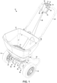
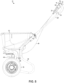
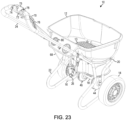
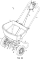
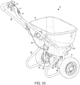
- the illustrative spreader 10 includes a container or hopper 12 into which particulate or granular material such as fertilizer, pesticides, herbicides, seed and the like are placed by a user.
- the hopper 12 may include a grate 13 or a grid disposed therein.
- the grate 13 is fabricated from metal, but other materials are contemplated herein.
- the hopper 12 is mounted to a base assembly 20, which is mounted to a support frame 22.
- a tubular handle 24 is detachably connected to the support frame 22.
- the support frame 22 may include axel mounting brackets 24, 26, each including one or more axel clearance openings configured to be intersected by or contained by an axle 18.
- a pair of wheels or tires 14, 16 is connected by the axel 18.
- the tires 14, 16 are constructed of polypropylene over foam rubber instead of being made of only plastic or rubber inflated with air.
- the tires 14, 16 may be referred to as a "never flat" tire. It should be appreciated that any other type of tire can be also be used.
- the support frame 22, base assembly 20, mounting brackets 24, 26, axle 18, and/or hopper 12 may comprise a variety of shapes, configurations, and materials. Illustrative materials may include, but not be limited to, metals, plastics, composites, combinations thereof, or the like.
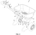
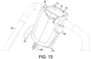
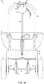
- rotors 34, 36 Located beneath the hopper 12 are two rotors 34, 36, which are driven by a gear system 40 connected to the wheels 14, 16 of the spreader 10 via axle 18.
- the gear system 40 includes a separate gearbox 44, 46 for each rotor 34, 36, respectively.
- the rotors 34, 36 distribute the granular material that is deposited thereon from the hopper 12 when the spreader 10 is moving (and therefore the rotors are rotating).
- Each of the rotors 34, 36 is connected to a different agitator 28, 29, respectively, by a shaft, rod, or cabling such that when the rotors 34, 36 rotate, the corresponding agitator 28, 29 rotates as well.
- the agitators 28, 29 may be positioned in the bottom portion of the hopper 12 and are configured to facilitate transmission of the granular material in the hopper 12 through the openings 50 onto the respective rotors 34, 36.
- the dual rotor configuration described herein provides improved distribution of granular material over single rotor configurations.
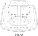
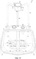
- the openings 50a, 50b, 50c, 50d are disposed within the hopper 12 such that the openings 50a, 50b are positioned over the rotor 34 and the openings 50c, 50d are positioned over the rotor 36.
- the openings 50 e.g., 50a, 50b, 50c, 50d
- openings 50 may also be formed in any other shape or configuration suitable for distributing the granular material to the rotors 34, 36.
- Various embodiments described herein may include a dual rotor system as described in U.S. Patent No. 5,203,510 . The dual rotor system of U.S. Patent No.
- 5,203,510 is constructed in a manner such that the discharge from each of the two individual impellers is controlled to achieve an additive distribution effect from each of the individual impellers resulting in a desired pattern of material distribution or coverage over a target area or treatment path or swath while avoiding undesirable skewing patterns and essentially eliminating centrally located coverage voids, thus addressing deficiencies of prior art dual rotor spreaders.
- each rotor 34, 36 may have a material deflection system 60.
- the material deflection system 60 of the various embodiments may include EdgeGuard ® technology. Such technology may prevent granular material or product from being thrown onto sidewalks, driveways, or other areas, as described in U.S. Patent No. 6,616,074 .
- the material deflection system 60 includes a pair of moveable deflectors 64, 66, one for each rotor 34, 36, respectively.
- the moveable deflectors 64, 66 include corresponding gear portions 67.
- the gear portions 67 of the moveable deflectors 64, 66 are configured such that rotation of the moveable deflector 64 in one direction (e.g., a clockwise direction when viewed from a bottom plan view of the spreader 10, FIG. 16 ) causes the moveable deflector 66 to rotate in the opposite direction (e.g., a counter-clockwise direction when viewed from a bottom plan view of the spreader 10, FIG. 16 ).
- the moveable deflector 64 is larger than the moveable deflector 66. That is, the moveable deflector 64 is configured to cover or block more of the rotor 34 than the amount of the rotor 36 blocked or covered by the moveable deflector 66.
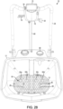
- the moveable deflectors 64, 66 may alternatively be configured to block or cover the same amount of the rotors 34, 36 or the moveable deflector 66 may be configured to block or cover more than the moveable deflector 64. Additionally, in some embodiments, either of the moveable deflectors 64, 66 may be configured not to block the corresponding rotor 34, 36 (see FIG. 19 ). In some embodiments, the moveable deflectors 64, 66 each include an aperture 63 sized and/or shaped to block a portion of the openings 50 of the hopper 12 when the material deflection system 60 is engaged or activated. For example, as illustratively shown in FIG.
- the apertures 63 of the moveable deflectors 64, 66 block a portion of each of the openings 50a, 50b and the openings 50c, 50d, respectively, of the hopper 12. It should be appreciated that the apertures 63 of the moveable deflectors 64, 66 may be sized or shaped to partially or completely block one or more of the openings 50 (e.g., openings 50a, 50b, 50c, and/or 50d) of the hopper 12 by any variety of amounts.
- the apertures 60 of the moveable deflectors 64, 66 may be sized to block approximately half of the inner-most openings 50b, 50c and approximately three-quarters of the outer-most openings 50a, 50d.
- the apertures 60 of the moveable deflectors 64, 66 may be sized to block any amount and any combination of the openings 50, in other embodiments.
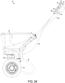
- a user or consumer may engage or activate the material deflection system 60 via a deflection activation lever 62, which may form part of the control assembly 70 of the spreader 10.
- the deflection activation lever 62 may be connected to an end (not shown) of a deflection activation cable or wire 68.
- the deflection activation wire 68 may be covered by a sheath or routed through a conduit.
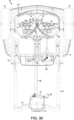
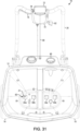
- the other end 69 of the deflection activation wire 68 may be connected to an aperture 65 or opening of the moveable deflector 64 such that when the position of the deflection activation lever 62 is moved from a disengaged state (see FIGS. 1-8 , 16 , and 17 ) to an engaged state (see FIGS. 22-31 ), the deflection activation wire 68 is pulled towards the control assembly 70 and the moveable deflector 64 is rotated into an engaged position.
- the spreader 10 includes a velocity measuring system or walking speed indicator assembly 80.
- This indicator assembly 80 may receive inputs from a gear assembly 82 connected to the agitator 28 (see FIGS. 7 and 15 ).
- the gear assembly 82 may instead be connected to the agitator 29.
- the gear assembly 82 transmits rotational movement of the agitator 28 to a stepper motor (not shown) via a wire or a shaft connected thereto.
- the stepper motor is configured to generate an amount of current based on linear velocity of the spreader 10 moved by the user or the consumer. That is, when a consumer pushes or pulls the spreader 10, the wheels rotate, which drive the gear system 40 connected to the wheels 14, 16.
- the gear system 40 of the spreader 10 in turn, drive the rotors 34, 36 and the agitators 28, 29 thereby generating rotational movement from linear movement of the spreader 10.
- the rotational movement generated therefrom is transmitted to the stepper motor via the gear assembly 82 and connecting wire or shaft.
- the amount of rotational movement generated may be a function of the speed or rate at which the user is pushing or pulling the spreader 10. As such, the faster the user pushes or pulls the spreader 10, the more current can be generated by the stepper motor.
- the spreader 10 may not include the walking speed indicator assembly 80.
- FIGS. 32-34 depict an illustrative embodiment of the spreader 10 without the walking speed indicator assembly 80.
- the walking speed indicator assembly 80 includes three light emitting diodes (LEDs) 84, 86, 88.
- the LED 84 may be a red LED to represent that the current speed is too slow
- the LED 86 may be a green LED to represent that the current speed is ideal
- the LED 88 may be another red LED to represent that the current speed is too fast. It should be appreciated that no separate power source is required since the integrated logic circuit and the indicator lights 84, 86, 88 are powered by current generated by the stepper motor.
- the walking speed indicator assembly 80 can include additional or other types of indicators (e.g., display screens, speakers, tactile generation devices, etc.), in other embodiments.
- the control assembly 70 may include a holder 72 for holding a portable electronic device (e.g., a smart phone, a personal music player, a tablet, a PDA, etc.).
- the holder 72 can include a lip 73 and/or a base surface 74 configured to retain at least a portion of the portable electronic device.
- the holder 70 also includes a securing mechanism 75 (e.g., an elastic band, a hook and loop strap, a tether, a clip, etc.) for securing at least a portion of the portable electronic device to the holder 70.
- a securing mechanism 75 e.g., an elastic band, a hook and loop strap, a tether, a clip, etc.
- the control assembly 70 includes a locking mechanism 78.
- the locking mechanism 78 is configured to lock or secure the distribution lever 78 in an engaged state.
- the shutter 21 can be in any shape or configuration suitable for exposing and covering the openings 50 of the hopper 12 (see FIGS. 20-21 ).
- the control assembly 20 of the spreader 10 may include a lock guard 79 or any other suitable structure for protecting the lock 78 from damage when the handle 24 is in a folded position.
Landscapes
- Life Sciences & Earth Sciences (AREA)
- Soil Sciences (AREA)
- Environmental Sciences (AREA)
- Engineering & Computer Science (AREA)
- Mechanical Engineering (AREA)
- Wood Science & Technology (AREA)
- Architecture (AREA)
- Pest Control & Pesticides (AREA)
- Structural Engineering (AREA)
- Zoology (AREA)
- Civil Engineering (AREA)
- Insects & Arthropods (AREA)
- Combustion & Propulsion (AREA)
- Transportation (AREA)
- Chemical & Material Sciences (AREA)
- Catching Or Destruction (AREA)
- Fertilizing (AREA)
- Sowing (AREA)
- Coating Apparatus (AREA)
Claims (13)
- Streuer (10), umfassend:einen Rahmen (22);einen Trichter (12), der mit dem Rahmen (22) verbunden ist und so gestaltet ist, dass er granuläres Material enthält, das über das Gelände oder andere Oberflächen gestreut werden soll;zwei Räder (14, 16), die drehbar mit dem Rahmen (22) verbunden sind;einen ersten Rotor (34) und einen zweiten Rotor (36), die drehbar mit dem Rahmen (22) unterhalb des Trichters (12) verbunden und so gestaltet sind, dass sie das granulare Material ausstreuen, wobei sich der erste und der zweite Rotor (34, 36) in entgegengesetzten Richtungen und unabhängig voneinander drehen;ein erstes Rührwerk (29), das mit dem ersten Rotor (34) über eine Welle, eine Stange oder ein Kabel verbunden ist, wobei das erste Rührwerk (29) so konfiguriert ist, dass es den Fluss von granularem Material aus dem Trichter (12) auf den ersten Rotor (34) erleichtert;ein zweites Rührwerk (28), das mit dem zweiten Rotor (36) über eine Welle, eine Stange oder ein Kabel verbunden ist, wobei das zweite Rührwerk (28) so konfiguriert ist, dass es den Fluss des granularen Materials aus dem Trichter (12) auf den zweiten Rotor (36) erleichtert;einen Antriebsstrang (40), der so konstruiert ist, dass er den ersten und den zweiten Rotor (34, 36) antreibt, wobei der Antriebsstrang (40) einen Antrieb von mindestens einem Rad (14, 16) erhält;dadurch gekennzeichnet, dass der Streuer ferner umfasst:eine Getriebeanordnung (82), die mit dem ersten Rührwerk (29) oder dem zweiten Rührwerk (28) verbunden ist;einen Schrittmotor, der mit der Getriebeanordnung (82) über einen Draht oder eine Welle verbunden ist, wobei der Schrittmotor so konfiguriert ist, dass er eine Strommenge auf der Grundlage einer linearen Geschwindigkeit des Streuers und in Abhängigkeit von der Drehbewegung des Rührwerks (28 oder 29) erzeugt, die von der Getriebeanordnung (82) auf den Schrittmotor übertragen wird;zwei quadratische Auslassöffnungen (50a, 50d), die im unteren Teil des Trichters (12) so angeordnet sind, dass jede der beiden Auslassöffnungen (50a, 50d) über einem anderen der ersten und zweiten Rotoren (34, 36) angeordnet ist, wobei jede Auslassöffnung (50a, 50d) so konfiguriert ist, dass sie den Fluss von granularem Material durch Schwerkraft vom Trichter (12) auf den anderen der ersten und zweiten Rotoren (34, 36) ermöglicht; undein Geschwindigkeitsmesssystem (80), das so konfiguriert ist, dass es die Drehgeschwindigkeit mindestens eines Rades (14, 16) in eine lineare Geschwindigkeit umwandelt, die lineare Geschwindigkeit mit einer vorgegebenen linearen Geschwindigkeit vergleicht und einem Benutzer eine Rückmeldung über die Ergebnisse des Vergleichs gibt.
- Streuer (10) nach Anspruch 1 umfasst ferner einen Indikator, der so angeordnet ist, dass er für den Benutzer sichtbar ist und die Rückmeldung liefert.
- Streuer (10) nach Anspruch 2, wobei die Anzeige drei Lichter (84, 86, 88) umfasst, wobei die drei Lichter jeweils die lineare Geschwindigkeit des Streuers (10) relativ zu der vorgegebenen linearen Geschwindigkeit anzeigen.
- Streuer (10) nach Anspruch 3, wobei die drei Leuchten (84, 86, 88) rote, grüne und rote Leuchten umfassen.
- Streuer (10) nach Anspruch 2, wobei die Rückmeldung eine Anzeige umfasst, dass die lineare Geschwindigkeit des Streuers (10) zu schnell, zu langsam oder innerhalb eines akzeptablen Referenzbereichs ist.
- Streuer (10) nach Anspruch 1, der ferner einen Halter (72) zum Halten eines tragbaren elektronischen Geräts umfasst, wobei der Halter (72) so angeordnet ist, dass er für den Benutzer während der Verwendung des Streuers (10) zugänglich ist.
- Streuer (10) nach Anspruch 1, wobei die Räder (14, 16) aus einem Schaumgummimaterial hergestellt sind.
- Streuer (10) nach Anspruch 1, wobei das granulare Material ein beliebiges eisschmelzendes Granulat, Düngemittel, Pestizide, Herbizide, granulatförmiges Bodenverbesserungsmaterial, granulatförmiges ölabsorbierendes Material, Staubsaugerprodukte, granulatförmiges Bodenreinigungsprodukt und Grassamen umfasst.
- Streuer (10) nach Anspruch 1, der ferner zwei zusätzliche quadratische Auslassöffnungen (50b, 50c) umfasst, die im unteren Teil des Trichters (12) so angeordnet sind, dass jede der zwei zusätzlichen quadratischen Auslassöffnungen (50b, 50c) über einem anderen der ersten und zweiten Rotoren (34, 36) angeordnet ist, wobei jede zusätzliche quadratische Auslassöffnung (50b, 50c) so konfiguriert ist, dass sie den Fluss von granularem Material durch Schwerkraft aus dem Trichter (12) auf den anderen der ersten und zweiten Rotoren (34, 36) ermöglicht.
- Streuer (10) nach Anspruch 1, der ferner eine integrierte Logikschaltung umfasst, die so konfiguriert ist, dass sie die vom Schrittmotor erzeugte Strommenge bestimmt und die bestimmte Strommenge mit einer Referenzstrommenge vergleicht, die einer idealen oder bevorzugten linearen Geschwindigkeit des Streuers (10) entspricht.
- Streuer (10) nach einem der Ansprüche 1 bis 10, der ferner ein Materialablenkungssystem (60) zum Blockieren mindestens eines Teils des von mindestens einem der ersten und zweiten Rotoren (34, 36) ausgestoßenen granularen Materials umfasst.
- Streuer (10) nach Anspruch 11, wobei das Materialablenkungssystem (60) eine erste bewegliche Ablenkeinrichtung (64) und eine zweite bewegliche Ablenkeinrichtung (66) umfasst, wobei sich die erste bewegliche Ablenkeinrichtung (64) in einer ersten Richtung dreht und sich die zweite bewegliche Ablenkeinrichtung (66) in einer zweiten, der ersten Richtung entgegengesetzten Richtung dreht; und
wobei die erste bewegliche Ablenkeinrichtung (64) mindestens einen Teil des ersten Rotors (34) blockiert, wenn er aktiviert wird, und die zweite bewegliche Ablenkeinrichtung (66) mindestens einen Teil des zweiten Rotors (36) blockiert, wenn er aktiviert wird. - Streuer (10) nach Anspruch 12, wobei die erste bewegliche Ablenkeinrichtung (64) und die zweite bewegliche Ablenkeinrichtung (66) zwischen mindestens einer ersten Position und einer zweiten Position bewegbar sind.
Applications Claiming Priority (2)
| Application Number | Priority Date | Filing Date | Title |
|---|---|---|---|
| US201762462794P | 2017-02-23 | 2017-02-23 | |
| PCT/US2018/019528 WO2018156958A1 (en) | 2017-02-23 | 2018-02-23 | Dual rotor spreader system |
Publications (3)
| Publication Number | Publication Date |
|---|---|
| EP3585143A1 EP3585143A1 (de) | 2020-01-01 |
| EP3585143A4 EP3585143A4 (de) | 2021-01-13 |
| EP3585143B1 true EP3585143B1 (de) | 2024-07-10 |
Family
ID=63254004
Family Applications (1)
| Application Number | Title | Priority Date | Filing Date |
|---|---|---|---|
| EP18757209.4A Active EP3585143B1 (de) | 2017-02-23 | 2018-02-23 | Zweischeibenstreusystem |
Country Status (10)
| Country | Link |
|---|---|
| US (1) | US11490561B2 (de) |
| EP (1) | EP3585143B1 (de) |
| JP (1) | JP7069193B2 (de) |
| KR (1) | KR20190128177A (de) |
| CN (1) | CN110602940B (de) |
| AU (1) | AU2018223782B2 (de) |
| CA (1) | CA3054310A1 (de) |
| IL (1) | IL268869A (de) |
| MX (1) | MX2019010047A (de) |
| WO (1) | WO2018156958A1 (de) |
Families Citing this family (6)
| Publication number | Priority date | Publication date | Assignee | Title |
|---|---|---|---|---|
| USD860261S1 (en) | 2017-02-24 | 2019-09-17 | Oms Investments, Inc. | Spreader |
| US11553641B2 (en) | 2018-12-18 | 2023-01-17 | Earthway Products Inc | Dual-impeller spreader with dual shut-off controls |
| DE102019135005A1 (de) | 2018-12-18 | 2020-06-18 | Earthway Products Inc | Doppellaufradstreuer mit doppelabsperrsteuerungen |
| US12274196B2 (en) * | 2021-09-17 | 2025-04-15 | Earthway Products Inc | Electric assist walk-behind spreader |
| US20230304242A1 (en) * | 2022-03-25 | 2023-09-28 | Douglas Dynamics, L.L.C. | Spreader or sprayer and control system therefore |
| US20240193707A1 (en) * | 2022-12-09 | 2024-06-13 | Dark Horse Ag Ventures Ltd. | Methods and systems for agricultural yield data management |
Family Cites Families (53)
| Publication number | Priority date | Publication date | Assignee | Title |
|---|---|---|---|---|
| CH170701A (fr) | 1932-03-14 | 1934-07-31 | Le Semoir Rotoportatif Soc | Semoir mécanique. |
| US2594084A (en) * | 1946-04-29 | 1952-04-22 | Skibbe Henry | Seed and fertilizer spreader |
| US3383055A (en) | 1965-12-02 | 1968-05-14 | Cyclone Seeder Co | Material spreader |
| US4032074A (en) | 1975-11-24 | 1977-06-28 | O. M. Scott & Sons Company | Material spreader |
| US4180184A (en) | 1978-03-29 | 1979-12-25 | Lambert Corporation | Fertilizer spreader |
| JPS5815474A (ja) * | 1981-07-17 | 1983-01-28 | Mitsubishi Electric Corp | 電動機駆動制御装置 |
| JPH0713457Y2 (ja) | 1988-04-09 | 1995-04-05 | 落合刃物工業株式会社 | 肥料散布機 |
| JPH0248201A (ja) | 1988-08-08 | 1990-02-19 | Aichi Tire Kogyo Kk | ハンドトラック用タイヤ及びその製造方法 |
| US5040711A (en) * | 1990-04-27 | 1991-08-20 | Niederhauser Robert D | Lawn mower apparatus for holding lawn care supplies |
| US5203510A (en) | 1990-12-28 | 1993-04-20 | The O. M. Scott & Sons Company | Dual rotary impeller broadcast spreaders |
| USD338894S (en) | 1991-02-14 | 1993-08-31 | White Castle System, Inc. | Material spreader |
| USD359963S (en) | 1994-06-10 | 1995-07-04 | The Toro Company | Granular fertilizer spreader attachment for lawn mower |
| USD373367S (en) | 1994-12-16 | 1996-09-03 | Republic Tool & Mfg. Corp. | Collapsible spreader |
| US5570814A (en) | 1994-12-16 | 1996-11-05 | Republic Tool & Mfg. Corp. | Collapsible broadcast spreader |
| USD376155S (en) | 1995-01-13 | 1996-12-03 | Republic Tool & Mfg. Corp. | Collapsible spreader |
| USD371780S (en) | 1995-01-19 | 1996-07-16 | Republic Tool & Mfg. Corp. | Rotary spreader |
| USD384679S (en) | 1996-07-08 | 1997-10-07 | Republic Tool & Mfg. Corp. | Broadcast spreader |
| US5842648A (en) | 1996-12-30 | 1998-12-01 | Republic Tool & Mfg. Corp. | Molded broadcast spreader |
| JPH11225652A (ja) * | 1997-12-04 | 1999-08-24 | American Cyanamid Co | 粒状物散布機および材料製品容器 |
| US6499679B1 (en) * | 1997-12-04 | 2002-12-31 | Basf Aktiengesellschaft | Granular spreader and product container |
| USD414783S (en) | 1998-12-11 | 1999-10-05 | O. Ames Co. | Broadcast spreader |
| USD413903S (en) | 1998-12-11 | 1999-09-14 | O. Ames Co. | Drop spreader |
| USD413904S (en) | 1999-02-16 | 1999-09-14 | O. Ames Co. | Dual mode spreader |
| US6138927A (en) * | 1999-03-01 | 2000-10-31 | O. Ames Co. | Dual mode spreader |
| US20020129883A1 (en) * | 2001-01-17 | 2002-09-19 | O'coin Bernard J. | Solid rubber tire with cellular foam rubber region |
| JP3857530B2 (ja) * | 2001-03-09 | 2006-12-13 | インターナショナル・ビジネス・マシーンズ・コーポレーション | ジョブ実行制御装置、方法、及びプログラム |
| US6616074B2 (en) | 2001-05-02 | 2003-09-09 | Oms Investments, Inc. | Broadcast spreader with movable deflector |
| US6945481B2 (en) * | 2001-09-27 | 2005-09-20 | Lesco Technologies, Llc | Dual mode spreader |
| CN2696296Y (zh) * | 2004-04-27 | 2005-05-04 | 何彦平 | 双圆盘离心式撒肥机 |
| SE0401202L (sv) * | 2004-05-10 | 2005-09-20 | Ksab Golf Equipment Ab | Spridare med två roterbara utkastarskivor |
| US7837073B2 (en) | 2005-01-14 | 2010-11-23 | Oms Investments, Inc. | Collapsible spreader |
| US20070244605A1 (en) * | 2006-04-12 | 2007-10-18 | Mark Hopkins | Monitoring devices for use with ground treatment equipment |
| US20080078850A1 (en) | 2006-09-15 | 2008-04-03 | Agri-Fab, Inc. | Spreader deflection plate apparatus and method |
| US8757521B2 (en) | 2008-05-09 | 2014-06-24 | Oms Investments, Inc. | Cartridge spreader system |
| CA133826S (en) | 2008-11-21 | 2010-05-03 | Smg Brands Inc | Product cartridge for a spreader |
| USD602046S1 (en) | 2009-03-10 | 2009-10-13 | Agri-Fab, Inc. | Push broadcast spreader |
| USD602045S1 (en) | 2009-03-10 | 2009-10-13 | Agri-Fab, Inc. | Tow broadcast spreader |
| US20110297763A1 (en) | 2010-06-06 | 2011-12-08 | Kressy Matthew S | Portable spreader for particulate matter |
| US9820430B2 (en) | 2011-10-27 | 2017-11-21 | Earthway Products, Inc. | Spread control mechanism |
| US9192094B2 (en) | 2011-10-27 | 2015-11-24 | Earthway Products, Inc. | Adaptable spreader |
| US20140257150A1 (en) | 2013-03-07 | 2014-09-11 | Zoll Medical Corporation | Providing Feedback for CPR Treatment |
| DE202013002363U1 (de) | 2013-03-12 | 2013-04-30 | Josef Straub | Handstreugutgerät, insbesondere für Streusalz, Sand, feinem Splitt und allen rieselfähigen Materialien |
| US9222231B2 (en) | 2013-03-15 | 2015-12-29 | Fred Marconi | Electrically powered hand spreader |
| JP5847107B2 (ja) * | 2013-03-27 | 2016-01-20 | 株式会社クボタ | 水田作業機 |
| USD718792S1 (en) | 2013-11-26 | 2014-12-02 | Ralph Lapham | Shovel |
| US10271537B2 (en) | 2015-04-28 | 2019-04-30 | Exmark Manufacturing Company, Incorporated | Motorized material broadcast spreader apparatus |
| US10499559B2 (en) * | 2016-12-15 | 2019-12-10 | Home Depot Product Authority, Llc | Handle mounted control system for a broadcast spreader |
| USD860261S1 (en) | 2017-02-24 | 2019-09-17 | Oms Investments, Inc. | Spreader |
| USD829773S1 (en) | 2017-05-10 | 2018-10-02 | Home Depot Product Authority, Llc | Broadcast spreader |
| CN108432427A (zh) * | 2018-05-03 | 2018-08-24 | 农业部南京农业机械化研究所 | 一种挂接式精准变量施肥机 |
| USD853446S1 (en) | 2018-05-08 | 2019-07-09 | Chapin Manufacturing, Inc. | Controlled-release spreader |
| USD873865S1 (en) | 2018-10-12 | 2020-01-28 | Chapin Manufacturing, Inc. | Particulate spreader |
| USD875789S1 (en) | 2018-11-27 | 2020-02-18 | Great Plains Manufacturing, Inc. | Spreader |
-
2018
- 2018-02-23 MX MX2019010047A patent/MX2019010047A/es unknown
- 2018-02-23 EP EP18757209.4A patent/EP3585143B1/de active Active
- 2018-02-23 CN CN201880025437.7A patent/CN110602940B/zh active Active
- 2018-02-23 AU AU2018223782A patent/AU2018223782B2/en active Active
- 2018-02-23 US US16/488,004 patent/US11490561B2/en active Active
- 2018-02-23 CA CA3054310A patent/CA3054310A1/en active Pending
- 2018-02-23 JP JP2019545999A patent/JP7069193B2/ja active Active
- 2018-02-23 WO PCT/US2018/019528 patent/WO2018156958A1/en not_active Ceased
- 2018-02-23 KR KR1020197027468A patent/KR20190128177A/ko not_active Ceased
-
2019
- 2019-08-22 IL IL26886919A patent/IL268869A/en unknown
Also Published As
| Publication number | Publication date |
|---|---|
| IL268869A (en) | 2019-10-31 |
| MX2019010047A (es) | 2019-10-30 |
| CA3054310A1 (en) | 2018-08-30 |
| AU2018223782A1 (en) | 2019-09-12 |
| JP2020508065A (ja) | 2020-03-19 |
| WO2018156958A1 (en) | 2018-08-30 |
| EP3585143A1 (de) | 2020-01-01 |
| JP7069193B2 (ja) | 2022-05-17 |
| NZ756627A (en) | 2025-02-28 |
| KR20190128177A (ko) | 2019-11-15 |
| CN110602940B (zh) | 2023-11-03 |
| EP3585143A4 (de) | 2021-01-13 |
| AU2018223782B2 (en) | 2024-03-21 |
| US20200053956A1 (en) | 2020-02-20 |
| CN110602940A (zh) | 2019-12-20 |
| US11490561B2 (en) | 2022-11-08 |
Similar Documents
| Publication | Publication Date | Title |
|---|---|---|
| EP3585143B1 (de) | Zweischeibenstreusystem | |
| US10595458B2 (en) | Powered hand-held spreader | |
| US11553641B2 (en) | Dual-impeller spreader with dual shut-off controls | |
| KR20120076917A (ko) | 동력수단이 구비된 소형 비료 살포기 | |
| JP2020508065A5 (de) | ||
| JP3212710U (ja) | 散布装置 | |
| KR101009994B1 (ko) | 소형 비료 살포기 | |
| EP3544408B1 (de) | Handgehaltener apparat zum ausstreuen von material | |
| HK40019878B (zh) | 双转子散布机系统 | |
| HK40019878A (en) | Dual rotor spreader system | |
| US10375877B2 (en) | Electric handheld broadcast spreader with pattern and speed controlling baffled skirt | |
| NZ756627B2 (en) | Dual rotor spreader system | |
| GB2582423A (en) | Dual-impeller spreader with dual shut-off controls | |
| NZ778222B2 (en) | Powered hand-held spreader | |
| KR101153209B1 (ko) | 자동 비료살포기 | |
| NZ778222A (en) | Powered hand-held spreader | |
| NZ740776B2 (en) | Powered hand-held spreader |
Legal Events
| Date | Code | Title | Description |
|---|---|---|---|
| STAA | Information on the status of an ep patent application or granted ep patent |
Free format text: STATUS: THE INTERNATIONAL PUBLICATION HAS BEEN MADE |
|
| PUAI | Public reference made under article 153(3) epc to a published international application that has entered the european phase |
Free format text: ORIGINAL CODE: 0009012 |
|
| STAA | Information on the status of an ep patent application or granted ep patent |
Free format text: STATUS: REQUEST FOR EXAMINATION WAS MADE |
|
| 17P | Request for examination filed |
Effective date: 20190822 |
|
| AK | Designated contracting states |
Kind code of ref document: A1 Designated state(s): AL AT BE BG CH CY CZ DE DK EE ES FI FR GB GR HR HU IE IS IT LI LT LU LV MC MK MT NL NO PL PT RO RS SE SI SK SM TR |
|
| AX | Request for extension of the european patent |
Extension state: BA ME |
|
| RIN1 | Information on inventor provided before grant (corrected) |
Inventor name: GLASSNER, ERIC Inventor name: BERGER, RYAN R. Inventor name: HSU, PAUL E. Inventor name: HERTRICH, JOHANNES Inventor name: WISNIEWSKI, DANIEL Inventor name: KNITTLE, JOHN |
|
| DAV | Request for validation of the european patent (deleted) | ||
| DAX | Request for extension of the european patent (deleted) | ||
| A4 | Supplementary search report drawn up and despatched |
Effective date: 20201216 |
|
| RIC1 | Information provided on ipc code assigned before grant |
Ipc: A01C 7/02 20060101ALI20201210BHEP Ipc: A01C 17/00 20060101ALI20201210BHEP Ipc: B62B 1/18 20060101ALN20201210BHEP Ipc: E01C 19/20 20060101ALI20201210BHEP Ipc: A01C 19/04 20060101ALI20201210BHEP Ipc: A01C 15/02 20060101AFI20201210BHEP Ipc: A01C 15/00 20060101ALI20201210BHEP |
|
| REG | Reference to a national code |
Ref country code: DE Free format text: PREVIOUS MAIN CLASS: A01C0015000000 Ipc: A01C0015020000 Ref country code: DE Ref legal event code: R079 Ref document number: 602018071580 Country of ref document: DE Free format text: PREVIOUS MAIN CLASS: A01C0015000000 Ipc: A01C0015020000 |
|
| RIC1 | Information provided on ipc code assigned before grant |
Ipc: B62B 1/18 20060101ALN20230721BHEP Ipc: A01C 15/00 20060101ALI20230721BHEP Ipc: E01C 19/20 20060101ALI20230721BHEP Ipc: A01C 7/02 20060101ALI20230721BHEP Ipc: A01C 19/04 20060101ALI20230721BHEP Ipc: A01C 17/00 20060101ALI20230721BHEP Ipc: A01C 15/02 20060101AFI20230721BHEP |
|
| GRAP | Despatch of communication of intention to grant a patent |
Free format text: ORIGINAL CODE: EPIDOSNIGR1 |
|
| RIC1 | Information provided on ipc code assigned before grant |
Ipc: B62B 1/18 20060101ALN20230801BHEP Ipc: A01C 15/00 20060101ALI20230801BHEP Ipc: E01C 19/20 20060101ALI20230801BHEP Ipc: A01C 7/02 20060101ALI20230801BHEP Ipc: A01C 19/04 20060101ALI20230801BHEP Ipc: A01C 17/00 20060101ALI20230801BHEP Ipc: A01C 15/02 20060101AFI20230801BHEP |
|
| STAA | Information on the status of an ep patent application or granted ep patent |
Free format text: STATUS: GRANT OF PATENT IS INTENDED |
|
| INTG | Intention to grant announced |
Effective date: 20230907 |
|
| GRAJ | Information related to disapproval of communication of intention to grant by the applicant or resumption of examination proceedings by the epo deleted |
Free format text: ORIGINAL CODE: EPIDOSDIGR1 |
|
| STAA | Information on the status of an ep patent application or granted ep patent |
Free format text: STATUS: REQUEST FOR EXAMINATION WAS MADE |
|
| GRAP | Despatch of communication of intention to grant a patent |
Free format text: ORIGINAL CODE: EPIDOSNIGR1 |
|
| STAA | Information on the status of an ep patent application or granted ep patent |
Free format text: STATUS: GRANT OF PATENT IS INTENDED |
|
| INTC | Intention to grant announced (deleted) | ||
| INTG | Intention to grant announced |
Effective date: 20240216 |
|
| RIC1 | Information provided on ipc code assigned before grant |
Ipc: B62B 1/18 20060101ALN20240205BHEP Ipc: A01C 15/00 20060101ALI20240205BHEP Ipc: E01C 19/20 20060101ALI20240205BHEP Ipc: A01C 7/02 20060101ALI20240205BHEP Ipc: A01C 19/04 20060101ALI20240205BHEP Ipc: A01C 17/00 20060101ALI20240205BHEP Ipc: A01C 15/02 20060101AFI20240205BHEP |
|
| GRAS | Grant fee paid |
Free format text: ORIGINAL CODE: EPIDOSNIGR3 |
|
| GRAA | (expected) grant |
Free format text: ORIGINAL CODE: 0009210 |
|
| STAA | Information on the status of an ep patent application or granted ep patent |
Free format text: STATUS: THE PATENT HAS BEEN GRANTED |
|
| AK | Designated contracting states |
Kind code of ref document: B1 Designated state(s): AL AT BE BG CH CY CZ DE DK EE ES FI FR GB GR HR HU IE IS IT LI LT LU LV MC MK MT NL NO PL PT RO RS SE SI SK SM TR |
|
| REG | Reference to a national code |
Ref country code: CH Ref legal event code: EP |
|
| REG | Reference to a national code |
Ref country code: DE Ref legal event code: R096 Ref document number: 602018071580 Country of ref document: DE |
|
| REG | Reference to a national code |
Ref country code: LT Ref legal event code: MG9D |
|
| REG | Reference to a national code |
Ref country code: NL Ref legal event code: MP Effective date: 20240710 |
|
| PG25 | Lapsed in a contracting state [announced via postgrant information from national office to epo] |
Ref country code: PT Free format text: LAPSE BECAUSE OF FAILURE TO SUBMIT A TRANSLATION OF THE DESCRIPTION OR TO PAY THE FEE WITHIN THE PRESCRIBED TIME-LIMIT Effective date: 20241111 |
|
| REG | Reference to a national code |
Ref country code: AT Ref legal event code: MK05 Ref document number: 1701156 Country of ref document: AT Kind code of ref document: T Effective date: 20240710 |
|
| PG25 | Lapsed in a contracting state [announced via postgrant information from national office to epo] |
Ref country code: NL Free format text: LAPSE BECAUSE OF FAILURE TO SUBMIT A TRANSLATION OF THE DESCRIPTION OR TO PAY THE FEE WITHIN THE PRESCRIBED TIME-LIMIT Effective date: 20240710 |
|
| PG25 | Lapsed in a contracting state [announced via postgrant information from national office to epo] |
Ref country code: PT Free format text: LAPSE BECAUSE OF FAILURE TO SUBMIT A TRANSLATION OF THE DESCRIPTION OR TO PAY THE FEE WITHIN THE PRESCRIBED TIME-LIMIT Effective date: 20241111 Ref country code: NL Free format text: LAPSE BECAUSE OF FAILURE TO SUBMIT A TRANSLATION OF THE DESCRIPTION OR TO PAY THE FEE WITHIN THE PRESCRIBED TIME-LIMIT Effective date: 20240710 |
|
| PG25 | Lapsed in a contracting state [announced via postgrant information from national office to epo] |
Ref country code: NO Free format text: LAPSE BECAUSE OF FAILURE TO SUBMIT A TRANSLATION OF THE DESCRIPTION OR TO PAY THE FEE WITHIN THE PRESCRIBED TIME-LIMIT Effective date: 20241010 |
|
| PG25 | Lapsed in a contracting state [announced via postgrant information from national office to epo] |
Ref country code: PL Free format text: LAPSE BECAUSE OF FAILURE TO SUBMIT A TRANSLATION OF THE DESCRIPTION OR TO PAY THE FEE WITHIN THE PRESCRIBED TIME-LIMIT Effective date: 20240710 Ref country code: GR Free format text: LAPSE BECAUSE OF FAILURE TO SUBMIT A TRANSLATION OF THE DESCRIPTION OR TO PAY THE FEE WITHIN THE PRESCRIBED TIME-LIMIT Effective date: 20241011 Ref country code: FI Free format text: LAPSE BECAUSE OF FAILURE TO SUBMIT A TRANSLATION OF THE DESCRIPTION OR TO PAY THE FEE WITHIN THE PRESCRIBED TIME-LIMIT Effective date: 20240710 |
|
| PG25 | Lapsed in a contracting state [announced via postgrant information from national office to epo] |
Ref country code: BG Free format text: LAPSE BECAUSE OF FAILURE TO SUBMIT A TRANSLATION OF THE DESCRIPTION OR TO PAY THE FEE WITHIN THE PRESCRIBED TIME-LIMIT Effective date: 20240710 |
|
| PG25 | Lapsed in a contracting state [announced via postgrant information from national office to epo] |
Ref country code: LV Free format text: LAPSE BECAUSE OF FAILURE TO SUBMIT A TRANSLATION OF THE DESCRIPTION OR TO PAY THE FEE WITHIN THE PRESCRIBED TIME-LIMIT Effective date: 20240710 |
|
| PG25 | Lapsed in a contracting state [announced via postgrant information from national office to epo] |
Ref country code: IS Free format text: LAPSE BECAUSE OF FAILURE TO SUBMIT A TRANSLATION OF THE DESCRIPTION OR TO PAY THE FEE WITHIN THE PRESCRIBED TIME-LIMIT Effective date: 20241110 Ref country code: AT Free format text: LAPSE BECAUSE OF FAILURE TO SUBMIT A TRANSLATION OF THE DESCRIPTION OR TO PAY THE FEE WITHIN THE PRESCRIBED TIME-LIMIT Effective date: 20240710 |
|
| PG25 | Lapsed in a contracting state [announced via postgrant information from national office to epo] |
Ref country code: HR Free format text: LAPSE BECAUSE OF FAILURE TO SUBMIT A TRANSLATION OF THE DESCRIPTION OR TO PAY THE FEE WITHIN THE PRESCRIBED TIME-LIMIT Effective date: 20240710 |
|
| PG25 | Lapsed in a contracting state [announced via postgrant information from national office to epo] |
Ref country code: ES Free format text: LAPSE BECAUSE OF FAILURE TO SUBMIT A TRANSLATION OF THE DESCRIPTION OR TO PAY THE FEE WITHIN THE PRESCRIBED TIME-LIMIT Effective date: 20240710 Ref country code: RS Free format text: LAPSE BECAUSE OF FAILURE TO SUBMIT A TRANSLATION OF THE DESCRIPTION OR TO PAY THE FEE WITHIN THE PRESCRIBED TIME-LIMIT Effective date: 20241010 |
|
| PG25 | Lapsed in a contracting state [announced via postgrant information from national office to epo] |
Ref country code: RS Free format text: LAPSE BECAUSE OF FAILURE TO SUBMIT A TRANSLATION OF THE DESCRIPTION OR TO PAY THE FEE WITHIN THE PRESCRIBED TIME-LIMIT Effective date: 20241010 Ref country code: PL Free format text: LAPSE BECAUSE OF FAILURE TO SUBMIT A TRANSLATION OF THE DESCRIPTION OR TO PAY THE FEE WITHIN THE PRESCRIBED TIME-LIMIT Effective date: 20240710 Ref country code: NO Free format text: LAPSE BECAUSE OF FAILURE TO SUBMIT A TRANSLATION OF THE DESCRIPTION OR TO PAY THE FEE WITHIN THE PRESCRIBED TIME-LIMIT Effective date: 20241010 Ref country code: LV Free format text: LAPSE BECAUSE OF FAILURE TO SUBMIT A TRANSLATION OF THE DESCRIPTION OR TO PAY THE FEE WITHIN THE PRESCRIBED TIME-LIMIT Effective date: 20240710 Ref country code: IS Free format text: LAPSE BECAUSE OF FAILURE TO SUBMIT A TRANSLATION OF THE DESCRIPTION OR TO PAY THE FEE WITHIN THE PRESCRIBED TIME-LIMIT Effective date: 20241110 Ref country code: HR Free format text: LAPSE BECAUSE OF FAILURE TO SUBMIT A TRANSLATION OF THE DESCRIPTION OR TO PAY THE FEE WITHIN THE PRESCRIBED TIME-LIMIT Effective date: 20240710 Ref country code: GR Free format text: LAPSE BECAUSE OF FAILURE TO SUBMIT A TRANSLATION OF THE DESCRIPTION OR TO PAY THE FEE WITHIN THE PRESCRIBED TIME-LIMIT Effective date: 20241011 Ref country code: FI Free format text: LAPSE BECAUSE OF FAILURE TO SUBMIT A TRANSLATION OF THE DESCRIPTION OR TO PAY THE FEE WITHIN THE PRESCRIBED TIME-LIMIT Effective date: 20240710 Ref country code: ES Free format text: LAPSE BECAUSE OF FAILURE TO SUBMIT A TRANSLATION OF THE DESCRIPTION OR TO PAY THE FEE WITHIN THE PRESCRIBED TIME-LIMIT Effective date: 20240710 Ref country code: BG Free format text: LAPSE BECAUSE OF FAILURE TO SUBMIT A TRANSLATION OF THE DESCRIPTION OR TO PAY THE FEE WITHIN THE PRESCRIBED TIME-LIMIT Effective date: 20240710 Ref country code: AT Free format text: LAPSE BECAUSE OF FAILURE TO SUBMIT A TRANSLATION OF THE DESCRIPTION OR TO PAY THE FEE WITHIN THE PRESCRIBED TIME-LIMIT Effective date: 20240710 |
|
| REG | Reference to a national code |
Ref country code: DE Ref legal event code: R097 Ref document number: 602018071580 Country of ref document: DE |
|
| PG25 | Lapsed in a contracting state [announced via postgrant information from national office to epo] |
Ref country code: RO Free format text: LAPSE BECAUSE OF FAILURE TO SUBMIT A TRANSLATION OF THE DESCRIPTION OR TO PAY THE FEE WITHIN THE PRESCRIBED TIME-LIMIT Effective date: 20240710 Ref country code: DK Free format text: LAPSE BECAUSE OF FAILURE TO SUBMIT A TRANSLATION OF THE DESCRIPTION OR TO PAY THE FEE WITHIN THE PRESCRIBED TIME-LIMIT Effective date: 20240710 Ref country code: SM Free format text: LAPSE BECAUSE OF FAILURE TO SUBMIT A TRANSLATION OF THE DESCRIPTION OR TO PAY THE FEE WITHIN THE PRESCRIBED TIME-LIMIT Effective date: 20240710 |
|
| PG25 | Lapsed in a contracting state [announced via postgrant information from national office to epo] |
Ref country code: EE Free format text: LAPSE BECAUSE OF FAILURE TO SUBMIT A TRANSLATION OF THE DESCRIPTION OR TO PAY THE FEE WITHIN THE PRESCRIBED TIME-LIMIT Effective date: 20240710 |
|
| PG25 | Lapsed in a contracting state [announced via postgrant information from national office to epo] |
Ref country code: CZ Free format text: LAPSE BECAUSE OF FAILURE TO SUBMIT A TRANSLATION OF THE DESCRIPTION OR TO PAY THE FEE WITHIN THE PRESCRIBED TIME-LIMIT Effective date: 20240710 |
|
| PG25 | Lapsed in a contracting state [announced via postgrant information from national office to epo] |
Ref country code: SK Free format text: LAPSE BECAUSE OF FAILURE TO SUBMIT A TRANSLATION OF THE DESCRIPTION OR TO PAY THE FEE WITHIN THE PRESCRIBED TIME-LIMIT Effective date: 20240710 Ref country code: IT Free format text: LAPSE BECAUSE OF FAILURE TO SUBMIT A TRANSLATION OF THE DESCRIPTION OR TO PAY THE FEE WITHIN THE PRESCRIBED TIME-LIMIT Effective date: 20240710 |
|
| PLBE | No opposition filed within time limit |
Free format text: ORIGINAL CODE: 0009261 |
|
| STAA | Information on the status of an ep patent application or granted ep patent |
Free format text: STATUS: NO OPPOSITION FILED WITHIN TIME LIMIT |
|
| 26N | No opposition filed |
Effective date: 20250411 |
|
| PG25 | Lapsed in a contracting state [announced via postgrant information from national office to epo] |
Ref country code: SE Free format text: LAPSE BECAUSE OF FAILURE TO SUBMIT A TRANSLATION OF THE DESCRIPTION OR TO PAY THE FEE WITHIN THE PRESCRIBED TIME-LIMIT Effective date: 20240710 |
|
| PG25 | Lapsed in a contracting state [announced via postgrant information from national office to epo] |
Ref country code: MC Free format text: LAPSE BECAUSE OF FAILURE TO SUBMIT A TRANSLATION OF THE DESCRIPTION OR TO PAY THE FEE WITHIN THE PRESCRIBED TIME-LIMIT Effective date: 20240710 |
|
| REG | Reference to a national code |
Ref country code: CH Ref legal event code: PL |
|
| PG25 | Lapsed in a contracting state [announced via postgrant information from national office to epo] |
Ref country code: LU Free format text: LAPSE BECAUSE OF NON-PAYMENT OF DUE FEES Effective date: 20250223 |
|
| PG25 | Lapsed in a contracting state [announced via postgrant information from national office to epo] |
Ref country code: CH Free format text: LAPSE BECAUSE OF NON-PAYMENT OF DUE FEES Effective date: 20250228 |
|
| REG | Reference to a national code |
Ref country code: BE Ref legal event code: MM Effective date: 20250228 |
|
| PG25 | Lapsed in a contracting state [announced via postgrant information from national office to epo] |
Ref country code: BE Free format text: LAPSE BECAUSE OF NON-PAYMENT OF DUE FEES Effective date: 20250228 |
|
| PG25 | Lapsed in a contracting state [announced via postgrant information from national office to epo] |
Ref country code: IE Free format text: LAPSE BECAUSE OF NON-PAYMENT OF DUE FEES Effective date: 20250223 |
|
| PGFP | Annual fee paid to national office [announced via postgrant information from national office to epo] |
Ref country code: GB Payment date: 20260227 Year of fee payment: 9 |
|
| PGFP | Annual fee paid to national office [announced via postgrant information from national office to epo] |
Ref country code: DE Payment date: 20260227 Year of fee payment: 9 |
|
| PGFP | Annual fee paid to national office [announced via postgrant information from national office to epo] |
Ref country code: FR Payment date: 20260225 Year of fee payment: 9 |