EP3585206B1 - Enveloppe de protection destinée à un appareil électronique - Google Patents
Enveloppe de protection destinée à un appareil électronique Download PDFInfo
- Publication number
- EP3585206B1 EP3585206B1 EP18711020.0A EP18711020A EP3585206B1 EP 3585206 B1 EP3585206 B1 EP 3585206B1 EP 18711020 A EP18711020 A EP 18711020A EP 3585206 B1 EP3585206 B1 EP 3585206B1
- Authority
- EP
- European Patent Office
- Prior art keywords
- cover according
- retaining lip
- retaining
- base element
- peripheral edge
- Prior art date
- Legal status (The legal status is an assumption and is not a legal conclusion. Google has not performed a legal analysis and makes no representation as to the accuracy of the status listed.)
- Not-in-force
Links
Images


Classifications
-
- A—HUMAN NECESSITIES
- A45—HAND OR TRAVELLING ARTICLES
- A45C—PURSES; LUGGAGE; HAND CARRIED BAGS
- A45C5/00—Rigid or semi-rigid luggage
- A45C5/02—Materials therefor
-
- A—HUMAN NECESSITIES
- A45—HAND OR TRAVELLING ARTICLES
- A45C—PURSES; LUGGAGE; HAND CARRIED BAGS
- A45C11/00—Receptacles for purposes not provided for in groups A45C1/00-A45C9/00
-
- A—HUMAN NECESSITIES
- A45—HAND OR TRAVELLING ARTICLES
- A45C—PURSES; LUGGAGE; HAND CARRIED BAGS
- A45C11/00—Receptacles for purposes not provided for in groups A45C1/00-A45C9/00
- A45C11/002—Receptacles for purposes not provided for in groups A45C1/00-A45C9/00 for storing portable handheld communication devices, e.g. pagers or smart phones
-
- A—HUMAN NECESSITIES
- A45—HAND OR TRAVELLING ARTICLES
- A45C—PURSES; LUGGAGE; HAND CARRIED BAGS
- A45C11/00—Receptacles for purposes not provided for in groups A45C1/00-A45C9/00
- A45C11/003—Receptacles for purposes not provided for in groups A45C1/00-A45C9/00 for storing portable computing devices, e.g. laptops, tablets or calculators
Definitions
- the invention relates to a case for an electronic device, in particular a mobile phone or a handheld computer, with a metal receptacle into which the device can be inserted, according to the preamble of claim 1.
- So-called cell phone cases made of plastic are widespread. These can be used for additional protection of the mobile radio device and also for the visual design and individualization of the device. Such covers made of plastic are susceptible to wear and aging, depending on the plastic material used. In addition, cases made of plastic are often perceived as a reduction in the perceived value of the sometimes high-priced mobile phones.
- a lockable container for portable radio-enabled devices continues from the DE 20 2014 008 506 U1 emerged.
- a sleeve made of metal is also provided, which is provided with a closure device for closing the device in the sleeve.
- the US 2012/0302294 A1 describes a housing for a mobile radio device, a lighting device being installed in a shell-shaped lower part.
- the device is held in the shell by means of a frame-like flange.
- a case for a mobile radio device having an inner frame with dampers for holding the mobile radio device and an outer frame which receives the inner frame in a non-positive manner.
- a back plate can be inserted into the inner frame.
- the US 2010/0203931 A1 discloses a cover for a mobile radio device, an outer cover made of hard plastic being provided in which an inner cover made of an elastomer is introduced.
- a generic cover for a mobile phone is from the FR 2 968 900 A1 known. This has a metal plate which is inserted into a plastic frame.
- the invention is based on the object of specifying a case for an electronic device which is compact and can be manufactured efficiently.
- a base element made of metal is provided and that a retaining lip made of an elastic material is arranged along an edge of the receiving shell.
- a basic idea of the invention can be seen in forming a receiving tray in which the device is to be inserted appropriately according to the shape of the electronic device, a retaining lip being arranged along an edge of a base element of the receiving tray.
- the device is held positively or non-positively in the holding shell by the holding lip made of an elastic material.
- the retaining lip can protrude inwards into the region of the receiving shell, the device being held detachably in the receiving shell.
- the retaining lip is arranged and dimensioned overall in such a way that a device can be used in a simple manner by deforming the retaining lip.
- the electronic device is, so to speak, clipped into the cradle and held by the retaining lip. In a corresponding manner, the electronic device can then be pushed out of the receiving shell and released again.
- the case according to the invention is particularly suitable for mobile telephones, in particular smartphones, and handheld computers, in particular so-called tablet computers.
- the case can also be designed and used for other electronic devices.
- the base element is shaped as an essentially flat plate and that the retaining lip forms a side wall area of the receiving shell.
- the base element can preferably be a flat metal sheet, the dimensions of which essentially correspond to a base area of the device to be accommodated.
- a retaining lip is attached to one edge of the plate-shaped base element, which lip extends essentially in accordance with the height or the thickness of the device.
- the metallic base element achieves a high level of stability, while the surrounding retaining lip, in particular made of a plastic or rubber material, ensures that the device is held in a reliable and shock-proof manner.
- a preferred embodiment of the invention consists in that the base element is formed from a metal sheet which has a sheet thickness of 0.2 mm to 2 mm, preferably of 0.5 mm to 1 mm.
- the metal can be a sheet steel, aluminum or some other suitable metal or metal alloy.
- a metal sheet is preferably selected which is sufficiently stable with the smallest possible sheet metal thickness and does not, or only insignificantly, influence the transmission and reception power of the device.
- a basic element can be formed from the sheet metal by deep drawing and can be work hardened in the process. Deep drawing can be carried out as ironing deep drawing, with an initial wall thickness being reduced even further. Depending on the degree of deformation, a targeted solidification of the material structure can be set, so that the use of material is reduced even further. A particularly good protective function of the cover is achieved in that it is largely or completely closed along its rear side and its side surfaces. A top side is left free so that a control panel, in particular a so-called touch screen, is freely accessible is.
- the recesses are preferably made in the area of buttons, cameras, microphones, loudspeaker openings, the brand or type designation of the device or at other locations necessary for the function in the receptacle.
- the introduction can take place by means of a punching or cutting process or material-removing by milling, drilling or in any other suitable manner.
- the metal in particular when using aluminum or an aluminum alloy, can be used without any surface treatment. This may even be preferred for a wanted technical impression.
- a particularly advantageous development of the invention can be seen in the fact that at least one outer side of the metallic base element is surface-treated, in particular shot-peened, sand-blasted, brushed, coated, chrome-plated or painted. In this way, a particularly noble and individual impression of the receiving shell can be created.
- the surface treatment can also be provided on the entire surface, that is to say also on the inside of the receiving shell. With a corresponding surface treatment, the appearance of value of the case and thus of a device inserted in it can be maintained or even increased.
- a housing made of a metal is viewed as particularly stable and valuable.
- the surface treatment and surface processing can also be used to apply a pattern, lettering, characters, labels, etc. This can be done for example by means of a laser, which is particularly useful when processing anodized aluminum material.
- the laser can remove the matt anodized surface layer and create shiny metal areas in a targeted manner.
- the retaining lip is arranged in areas or along the entire edge of the base element.
- the retaining lip can be arranged only in corner areas or at certain points of the base element.
- the retaining lip can be formed from any suitable material which enables the electronic device to be reliably held in the receiving shell.
- the retaining lip forms an undercut on the receiving shell.
- a further preferred embodiment of the invention consists in that in the retaining lip, which forms a wall area of the receiving shell, recesses for Functional areas are provided.
- the functional areas can in particular be line connections, for example for a charging cable, and for adjustment buttons, for example for switching on and off or for volume regulation.
- the retaining lip is formed from an elastic material, in particular a rubber material.
- the rubber material can be arranged not only on the edge of the receiving shell but also in corner areas or other locations on the outside as an additional impact protection and / or also on certain areas of the inside. An arrangement along the inside can contribute to a certain frictional retention and a cushioning mounting of the device in the receiving shell.
- a particularly good fixation of the device with a further good releasability from the receiving shell can be achieved according to an embodiment variant of the invention in that the retaining lip protrudes inward between 0.5 mm and 4 mm. Depending on the device size, different dimensions can also be provided.
- the retaining lip protrudes axially with respect to the device inserted in the receiving shell. This makes it possible, for example, to place the receiving tray with a touchscreen facing down on a surface without contacting the exposed side of the device. This also protects the device and ensures good functionality.
- a particularly efficient attachment of the retaining lip is achieved according to the invention in that the retaining lip is molded onto the edge, namely is cast on or extruded onto it.
- the retaining lip is formed from a plastic material, which is preferably a thermoplastic. This is poured or extruded onto the edge in a softened, in particular melted, state. When the retaining lip cools and solidifies, a firm connection to the receiving shell is created.
- the receiving tray has an additional holding area which is designed for receiving small objects, preferably money or cards.
- a mobile phone for example, can take on the function of a wallet.
- the holding area can in particular be provided in the form of a slot with one or more slots or formations for receiving banknotes and cards, such as payment or credit cards.
- a particularly advantageous embodiment variant consists in that the holding area has a pocket-shaped receptacle.
- a receiving area can be provided between the receiving shell and the device used. An insertion of money can be done either through a slot or by loosening and reinserting the device in the receiving tray.
- the holding area has a holding element, preferably a clamp or a magnetic element.
- a holding element preferably a clamp
- banknotes or payment cards can be clamped or clipped in place.
- the holding element can be a magnetic element. This means that the holding element is designed to be magnetic, at least in some areas. In this way, narrow objects, such as money or payment cards, can be clamped magnetically between the metallic receiving shell and the holding element.
- a casing 10 not according to the invention according to FIG Fig. 1 has a metallic base element 11, which is deep-drawn from sheet metal and shaped into a receiving shell 12.
- the receiving shell 12 comprises a plate-shaped bottom area 14, to which side wall areas 16 are connected all the way around.
- the receiving shell 12 is designed overall so that a mobile phone (not shown) can be suitably received therein.
- Recesses 18a for connections are made in a lower side wall region 16.
- Elongated recesses 18b for buttons or switches are formed in the lateral side wall areas 16.
- a recess 18c for a camera lens is made in an upper corner area and a recess 18d for a brand emblem on the back of the cell phone to be used is made in a central area.
- the rear recess 18d serves as an engaging hole for pushing the inserted device out of the receiving tray 12 from behind.
- a marginal edge 20 on the metallic receiving shell 12 can be thickened and / or rounded by a certain upsetting.
- a frame-like, circumferential retaining lip 30 is attached to the marginal edge 20.
- the retaining lip 30 can be pushed on and glued on. It is also possible to cast on or extrude the retaining lip 30 made of a flexible plastic material directly onto the edge 20.
- the retaining lip 30 is approximately T-shaped or angular, with a lip-like area protruding further inward. This area forms an undercut and rests positively and / or non-positively on an inserted electronic device and holds it reliably in the receiving shell 12.
- the retaining lip 30 is designed so that the electronic device can be opened by a slight pressure on the The rear side, for example through the recess 18d, can be removed from the receiving shell 12 again.
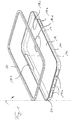
- a metallic base element 11 is designed as a substantially rectangular plate. Openings 13 for improved connection of a retaining lip 30 made of a soft elastic material are provided along an edge 20 of the plate-shaped base element 11.
- the retaining lip 30 forms a side wall area 16, so that a receiving tray 12 for a device 5, in particular a mobile phone, is formed by the metallic base element 11, which forms a base plate 14, and the retaining lip 30 attached around it.
- the holding lip 30 is correspondingly contoured on its inside for receiving the device 5, an elastic undercut being formed as a result.
- the retaining lip 30 is preferably molded onto the metallic base plate 14 in an injection molding process.
- Corresponding recesses 18 a for functional elements of the device 5 are provided in the retaining lip 30.
- a recess 18c for a camera lens and a recess 18d, for example for a camera lens, are also made on the metallic base element 11.
Landscapes
- Chemical & Material Sciences (AREA)
- Engineering & Computer Science (AREA)
- Materials Engineering (AREA)
- Telephone Set Structure (AREA)
- Casings For Electric Apparatus (AREA)
Claims (14)
- Enveloppe pour un appareil électronique (5), en particulier un téléphone mobile ou un ordinateur de poche, avec une coque de réception (12) avec du métal, dans laquelle l'appareil (5) peut être introduit de manière ajustée, dans laquelle- un élément de base (11) est prévu en métal, lequel est formé comme une plaque sensiblement plane, et- une lèvre de retenue (30) en un matériau élastique est agencée le long d'une arête de bord (20) de l'élément de base (11) en forme de plaque, dans laquelle la lèvre de retenue (30) forme une zone de paroi latérale (16) de la coque de réception (12), caractérisée en ce- que le matériau élastique est une matière thermoplastique qui est coulée ou extrudée dans un état fondu sur l'arête de bord (20), et- que des ouvertures (13) sont prévues le long de l'arête de bord (20) de l'élément de base (11) en forme de plaque pour la liaison améliorée de la lèvre de retenue (30) coulée ou extrudée.
- Enveloppe selon la revendication 1,
caractérisée en ce
que la lèvre de retenue (30) dépasse vers l'intérieur dans la zone de la coque de réception (12), l'appareil (5) étant maintenu de manière détachable dans la coque de réception (12). - Enveloppe selon la revendication 1,
caractérisée en ce
que la lèvre de retenue (30) est réalisée pour la fixation de la lèvre de retenue (30) à l'arête de bord (20) avec une ou plusieurs saillies de type pince de serrage le long de l'arête de bord (20). - Enveloppe selon l'une des revendications 1 à 3,
caractérisée en ce
que l'élément de base (11) est formé en une tôle métallique qui présente une épaisseur de tôle de 0,2 mm à 2 mm, de préférence de 0,5 mm à 1 mm. - Enveloppe selon l'une des revendications 1 à 4,
caractérisée en ce
que la lèvre de retenue (30) est en un matériau de caoutchouc. - Enveloppe selon l'une des revendications 1 à 5,
caractérisée en ce
que des évidements (18) pour des zones fonctionnelles et/ou pour une désignation de marque de l'appareil (5) sont ménagés dans l'élément de base (11) métallique. - Enveloppe selon l'une des revendications 1 à 6,
caractérisée en ce
qu'au moins un côté extérieur de l'élément de base (11) est traité en surface, en particulier est grenaillé, sablé, brossé, revêtu, chromé ou laqué. - Enveloppe selon l'une des revendications 1 à 7,
caractérisée en ce
que la lèvre de retenue (30) est agencée par endroits ou le long de l'arête de bord (20) entière de l'élément de base (11). - Enveloppe selon l'une des revendications 1 à 8,
caractérisée en ce
que des évidements (18) pour des zones fonctionnelles sont prévus dans la lèvre de retenue (30) qui forme une zone de paroi (16) de la coque de réception (12). - Enveloppe selon l'une des revendications 1 à 9,
caractérisée en ce
que la lèvre de retenue (30) dépasse entre 0,5 mm et 4 mm vers l'intérieur. - Enveloppe selon l'une des revendications 1 à 10,
caractérisée en ce
que la lèvre de retenue (30) dépasse axialement par rapport à l'appareil (5) inséré dans la coque de réception (12). - Enveloppe selon l'une des revendications 1 à 11,
caractérisée en ce
que la coque de réception (12) présente une zone de retenue supplémentaire qui est réalisée pour la réception de petits objets, de préférence d'argent ou de cartes. - Enveloppe selon la revendication 12,
caractérisée en ce
que la zone de retenue présente un logement en forme de poche. - Enveloppe selon la revendication 12 ou 13,
caractérisée en ce
que la zone de retenue présente un élément de retenue, de préférence une pince de serrage ou un élément magnétique.
Applications Claiming Priority (3)
| Application Number | Priority Date | Filing Date | Title |
|---|---|---|---|
| DE202017101013 | 2017-02-23 | ||
| DE202017104546.3U DE202017104546U1 (de) | 2017-02-23 | 2017-07-31 | Hülle für ein elektronisches Gerät |
| PCT/EP2018/054454 WO2018154029A1 (fr) | 2017-02-23 | 2018-02-23 | Enveloppe de protection destinée à un appareil électronique |
Publications (2)
| Publication Number | Publication Date |
|---|---|
| EP3585206A1 EP3585206A1 (fr) | 2020-01-01 |
| EP3585206B1 true EP3585206B1 (fr) | 2021-10-27 |
Family
ID=60163095
Family Applications (1)
| Application Number | Title | Priority Date | Filing Date |
|---|---|---|---|
| EP18711020.0A Not-in-force EP3585206B1 (fr) | 2017-02-23 | 2018-02-23 | Enveloppe de protection destinée à un appareil électronique |
Country Status (3)
| Country | Link |
|---|---|
| EP (1) | EP3585206B1 (fr) |
| DE (1) | DE202017104546U1 (fr) |
| WO (1) | WO2018154029A1 (fr) |
Families Citing this family (2)
| Publication number | Priority date | Publication date | Assignee | Title |
|---|---|---|---|---|
| WO2020197557A1 (fr) * | 2019-03-28 | 2020-10-01 | Hewlett-Packard Development Company, L.P. | Couvercles pour dispositifs électroniques |
| CN113905120B (zh) * | 2020-07-06 | 2023-05-26 | 深圳市中创卓越科技有限公司 | 移动终端保护壳 |
Family Cites Families (8)
| Publication number | Priority date | Publication date | Assignee | Title |
|---|---|---|---|---|
| EP1003914A1 (fr) | 1997-08-05 | 2000-05-31 | Ambion, Inc. | Procedes et compositions de stripage d'acides nucleiques |
| DE19828193C2 (de) | 1998-06-24 | 2002-11-28 | Stefan Worlitzer | Schutzetui für Mobiltelefone |
| US20090194444A1 (en) * | 2006-10-24 | 2009-08-06 | Darren Jones | Electronics Device Case |
| US8755852B2 (en) * | 2009-02-06 | 2014-06-17 | Speculative Product Design, Llc | One piece co-formed exterior hard shell case with an elastomeric liner for mobile electronic devices |
| US9294601B2 (en) | 2011-05-23 | 2016-03-22 | Alexander H Hammond | Illuminated cell phone case |
| US8695798B2 (en) * | 2012-01-09 | 2014-04-15 | Case-Mate, Inc. | Case for electronic devices |
| WO2015022675A1 (fr) * | 2013-08-15 | 2015-02-19 | Bergstrom Anton Wayne | Étui de dispositif mobile et module caractéristique |
| DE202014008506U1 (de) | 2014-10-24 | 2015-01-15 | Eben Basis Gmbh | Verschließbarer Behälter für tragbare funkfähige Geräte |
-
2017
- 2017-07-31 DE DE202017104546.3U patent/DE202017104546U1/de not_active Expired - Lifetime
-
2018
- 2018-02-23 EP EP18711020.0A patent/EP3585206B1/fr not_active Not-in-force
- 2018-02-23 WO PCT/EP2018/054454 patent/WO2018154029A1/fr not_active Ceased
Also Published As
| Publication number | Publication date |
|---|---|
| EP3585206A1 (fr) | 2020-01-01 |
| DE202017104546U1 (de) | 2017-10-05 |
| WO2018154029A1 (fr) | 2018-08-30 |
Similar Documents
| Publication | Publication Date | Title |
|---|---|---|
| DE69716885T2 (de) | Elektronisches gerät mit zusätzlichem gehäuse | |
| EP1523842B1 (fr) | Contenant, notamment boitier de partie de telephone mobile et procede de production d'une partie de boitier | |
| EP3585206B1 (fr) | Enveloppe de protection destinée à un appareil électronique | |
| EP1090464A1 (fr) | Etui de protection pour telephones mobiles | |
| DE4445840A1 (de) | Handapparat für Telefon- und Funksprechsysteme | |
| DE102011054346B3 (de) | Halter für ein elektronisches Gerät | |
| DE60306498T2 (de) | Stossfeste flüssigkristallanzeigeanordnung | |
| DE102013106649A1 (de) | Halter für ein elektronisches Gerät | |
| DE202015005102U1 (de) | Bildschirmständer für zwei Bildschirme mit einem Gehäuse für elektrische Komponenten | |
| DE202009006513U1 (de) | Abdeckung, Individualisierungsmittel sowie Schmuck- und/oder Schutzeinrichtung für mobile Multimedia- oder andere elektronische Endgeräte wie insbesondere Mobiltelefone | |
| DE202009005948U1 (de) | Vorrichtung zur Aufnahme eines kartenartigen Datenschildes | |
| DE102009009729A1 (de) | Türaußengriff, insbesondere für Fahrzeuge sowie Verfahren zu dessen Herstellung | |
| DE4228632C1 (fr) | ||
| DE2834238A1 (de) | vorrichtung zum von-vorn-befestigen eines lautsprechers am bzw. im schalldurchbruch einer tragwand | |
| DE102018130600A1 (de) | Magnetischer Blickschutzfilter | |
| EP3079140A2 (fr) | Dispositif d'ecran echangeable a double couche | |
| DE102014013103A1 (de) | Montageeinheit und Verfahren für das Einbauen eines elektrischen Moduls | |
| EP2610818A2 (fr) | Boîtier, en particulier pour une clé électronique | |
| DE10139480B4 (de) | Halterung für ein Mobiltelefon im Kraftfahrzeug | |
| DE10063574C1 (de) | Halterung | |
| DE102009002832A1 (de) | Abdeckung für mobile Multimedia- oder andere elektronische Endgeräte wie insbesondere Mobiltelefone | |
| DE4413129C2 (de) | Wassergeschütztes elektrisches Gerät | |
| DE102024107694A1 (de) | Hülle für ein mobiles Endgerät, vorzugsweise für ein Smartphone | |
| DE102009002830A1 (de) | Individualisierungsmittel für mobile Multimedia- oder andere elektronische Endgeräte wie insbesondere Mobiltelefone | |
| DE102009002831A1 (de) | Schmuck- und/oder Schutzeinrichtung für mobile Multimedia- oder andere elektronische Endgeräte wie insbersondere Mobiltelefone |
Legal Events
| Date | Code | Title | Description |
|---|---|---|---|
| STAA | Information on the status of an ep patent application or granted ep patent |
Free format text: STATUS: UNKNOWN |
|
| STAA | Information on the status of an ep patent application or granted ep patent |
Free format text: STATUS: THE INTERNATIONAL PUBLICATION HAS BEEN MADE |
|
| PUAI | Public reference made under article 153(3) epc to a published international application that has entered the european phase |
Free format text: ORIGINAL CODE: 0009012 |
|
| STAA | Information on the status of an ep patent application or granted ep patent |
Free format text: STATUS: REQUEST FOR EXAMINATION WAS MADE |
|
| 17P | Request for examination filed |
Effective date: 20190627 |
|
| AK | Designated contracting states |
Kind code of ref document: A1 Designated state(s): AL AT BE BG CH CY CZ DE DK EE ES FI FR GB GR HR HU IE IS IT LI LT LU LV MC MK MT NL NO PL PT RO RS SE SI SK SM TR |
|
| AX | Request for extension of the european patent |
Extension state: BA ME |
|
| DAV | Request for validation of the european patent (deleted) | ||
| DAX | Request for extension of the european patent (deleted) | ||
| REG | Reference to a national code |
Ref country code: HK Ref legal event code: DE Ref document number: 40014653 Country of ref document: HK |
|
| GRAP | Despatch of communication of intention to grant a patent |
Free format text: ORIGINAL CODE: EPIDOSNIGR1 |
|
| STAA | Information on the status of an ep patent application or granted ep patent |
Free format text: STATUS: GRANT OF PATENT IS INTENDED |
|
| INTG | Intention to grant announced |
Effective date: 20210601 |
|
| GRAS | Grant fee paid |
Free format text: ORIGINAL CODE: EPIDOSNIGR3 |
|
| GRAA | (expected) grant |
Free format text: ORIGINAL CODE: 0009210 |
|
| STAA | Information on the status of an ep patent application or granted ep patent |
Free format text: STATUS: THE PATENT HAS BEEN GRANTED |
|
| AK | Designated contracting states |
Kind code of ref document: B1 Designated state(s): AL AT BE BG CH CY CZ DE DK EE ES FI FR GB GR HR HU IE IS IT LI LT LU LV MC MK MT NL NO PL PT RO RS SE SI SK SM TR |
|
| REG | Reference to a national code |
Ref country code: GB Ref legal event code: FG4D Free format text: NOT ENGLISH |
|
| REG | Reference to a national code |
Ref country code: CH Ref legal event code: EP |
|
| REG | Reference to a national code |
Ref country code: AT Ref legal event code: REF Ref document number: 1441045 Country of ref document: AT Kind code of ref document: T Effective date: 20211115 |
|
| REG | Reference to a national code |
Ref country code: DE Ref legal event code: R096 Ref document number: 502018007581 Country of ref document: DE |
|
| REG | Reference to a national code |
Ref country code: IE Ref legal event code: FG4D Free format text: LANGUAGE OF EP DOCUMENT: GERMAN |
|
| REG | Reference to a national code |
Ref country code: LT Ref legal event code: MG9D |
|
| REG | Reference to a national code |
Ref country code: NL Ref legal event code: MP Effective date: 20211027 |
|
| PG25 | Lapsed in a contracting state [announced via postgrant information from national office to epo] |
Ref country code: RS Free format text: LAPSE BECAUSE OF FAILURE TO SUBMIT A TRANSLATION OF THE DESCRIPTION OR TO PAY THE FEE WITHIN THE PRESCRIBED TIME-LIMIT Effective date: 20211027 Ref country code: LT Free format text: LAPSE BECAUSE OF FAILURE TO SUBMIT A TRANSLATION OF THE DESCRIPTION OR TO PAY THE FEE WITHIN THE PRESCRIBED TIME-LIMIT Effective date: 20211027 Ref country code: FI Free format text: LAPSE BECAUSE OF FAILURE TO SUBMIT A TRANSLATION OF THE DESCRIPTION OR TO PAY THE FEE WITHIN THE PRESCRIBED TIME-LIMIT Effective date: 20211027 Ref country code: BG Free format text: LAPSE BECAUSE OF FAILURE TO SUBMIT A TRANSLATION OF THE DESCRIPTION OR TO PAY THE FEE WITHIN THE PRESCRIBED TIME-LIMIT Effective date: 20220127 |
|
| PG25 | Lapsed in a contracting state [announced via postgrant information from national office to epo] |
Ref country code: IS Free format text: LAPSE BECAUSE OF FAILURE TO SUBMIT A TRANSLATION OF THE DESCRIPTION OR TO PAY THE FEE WITHIN THE PRESCRIBED TIME-LIMIT Effective date: 20220227 Ref country code: SE Free format text: LAPSE BECAUSE OF FAILURE TO SUBMIT A TRANSLATION OF THE DESCRIPTION OR TO PAY THE FEE WITHIN THE PRESCRIBED TIME-LIMIT Effective date: 20211027 Ref country code: PT Free format text: LAPSE BECAUSE OF FAILURE TO SUBMIT A TRANSLATION OF THE DESCRIPTION OR TO PAY THE FEE WITHIN THE PRESCRIBED TIME-LIMIT Effective date: 20220228 Ref country code: PL Free format text: LAPSE BECAUSE OF FAILURE TO SUBMIT A TRANSLATION OF THE DESCRIPTION OR TO PAY THE FEE WITHIN THE PRESCRIBED TIME-LIMIT Effective date: 20211027 Ref country code: NO Free format text: LAPSE BECAUSE OF FAILURE TO SUBMIT A TRANSLATION OF THE DESCRIPTION OR TO PAY THE FEE WITHIN THE PRESCRIBED TIME-LIMIT Effective date: 20220127 Ref country code: NL Free format text: LAPSE BECAUSE OF FAILURE TO SUBMIT A TRANSLATION OF THE DESCRIPTION OR TO PAY THE FEE WITHIN THE PRESCRIBED TIME-LIMIT Effective date: 20211027 Ref country code: LV Free format text: LAPSE BECAUSE OF FAILURE TO SUBMIT A TRANSLATION OF THE DESCRIPTION OR TO PAY THE FEE WITHIN THE PRESCRIBED TIME-LIMIT Effective date: 20211027 Ref country code: HR Free format text: LAPSE BECAUSE OF FAILURE TO SUBMIT A TRANSLATION OF THE DESCRIPTION OR TO PAY THE FEE WITHIN THE PRESCRIBED TIME-LIMIT Effective date: 20211027 Ref country code: GR Free format text: LAPSE BECAUSE OF FAILURE TO SUBMIT A TRANSLATION OF THE DESCRIPTION OR TO PAY THE FEE WITHIN THE PRESCRIBED TIME-LIMIT Effective date: 20220128 Ref country code: ES Free format text: LAPSE BECAUSE OF FAILURE TO SUBMIT A TRANSLATION OF THE DESCRIPTION OR TO PAY THE FEE WITHIN THE PRESCRIBED TIME-LIMIT Effective date: 20211027 |
|
| REG | Reference to a national code |
Ref country code: DE Ref legal event code: R097 Ref document number: 502018007581 Country of ref document: DE |
|
| PG25 | Lapsed in a contracting state [announced via postgrant information from national office to epo] |
Ref country code: SM Free format text: LAPSE BECAUSE OF FAILURE TO SUBMIT A TRANSLATION OF THE DESCRIPTION OR TO PAY THE FEE WITHIN THE PRESCRIBED TIME-LIMIT Effective date: 20211027 Ref country code: SK Free format text: LAPSE BECAUSE OF FAILURE TO SUBMIT A TRANSLATION OF THE DESCRIPTION OR TO PAY THE FEE WITHIN THE PRESCRIBED TIME-LIMIT Effective date: 20211027 Ref country code: RO Free format text: LAPSE BECAUSE OF FAILURE TO SUBMIT A TRANSLATION OF THE DESCRIPTION OR TO PAY THE FEE WITHIN THE PRESCRIBED TIME-LIMIT Effective date: 20211027 Ref country code: EE Free format text: LAPSE BECAUSE OF FAILURE TO SUBMIT A TRANSLATION OF THE DESCRIPTION OR TO PAY THE FEE WITHIN THE PRESCRIBED TIME-LIMIT Effective date: 20211027 Ref country code: DK Free format text: LAPSE BECAUSE OF FAILURE TO SUBMIT A TRANSLATION OF THE DESCRIPTION OR TO PAY THE FEE WITHIN THE PRESCRIBED TIME-LIMIT Effective date: 20211027 Ref country code: CZ Free format text: LAPSE BECAUSE OF FAILURE TO SUBMIT A TRANSLATION OF THE DESCRIPTION OR TO PAY THE FEE WITHIN THE PRESCRIBED TIME-LIMIT Effective date: 20211027 |
|
| PLBE | No opposition filed within time limit |
Free format text: ORIGINAL CODE: 0009261 |
|
| STAA | Information on the status of an ep patent application or granted ep patent |
Free format text: STATUS: NO OPPOSITION FILED WITHIN TIME LIMIT |
|
| PG25 | Lapsed in a contracting state [announced via postgrant information from national office to epo] |
Ref country code: MC Free format text: LAPSE BECAUSE OF FAILURE TO SUBMIT A TRANSLATION OF THE DESCRIPTION OR TO PAY THE FEE WITHIN THE PRESCRIBED TIME-LIMIT Effective date: 20211027 |
|
| 26N | No opposition filed |
Effective date: 20220728 |
|
| REG | Reference to a national code |
Ref country code: CH Ref legal event code: PL |
|
| REG | Reference to a national code |
Ref country code: BE Ref legal event code: MM Effective date: 20220228 |
|
| GBPC | Gb: european patent ceased through non-payment of renewal fee |
Effective date: 20220223 |
|
| PG25 | Lapsed in a contracting state [announced via postgrant information from national office to epo] |
Ref country code: LU Free format text: LAPSE BECAUSE OF NON-PAYMENT OF DUE FEES Effective date: 20220223 Ref country code: AL Free format text: LAPSE BECAUSE OF FAILURE TO SUBMIT A TRANSLATION OF THE DESCRIPTION OR TO PAY THE FEE WITHIN THE PRESCRIBED TIME-LIMIT Effective date: 20211027 |
|
| PG25 | Lapsed in a contracting state [announced via postgrant information from national office to epo] |
Ref country code: SI Free format text: LAPSE BECAUSE OF FAILURE TO SUBMIT A TRANSLATION OF THE DESCRIPTION OR TO PAY THE FEE WITHIN THE PRESCRIBED TIME-LIMIT Effective date: 20211027 |
|
| PG25 | Lapsed in a contracting state [announced via postgrant information from national office to epo] |
Ref country code: FR Free format text: LAPSE BECAUSE OF NON-PAYMENT OF DUE FEES Effective date: 20220228 |
|
| PG25 | Lapsed in a contracting state [announced via postgrant information from national office to epo] |
Ref country code: LI Free format text: LAPSE BECAUSE OF NON-PAYMENT OF DUE FEES Effective date: 20220228 Ref country code: IE Free format text: LAPSE BECAUSE OF NON-PAYMENT OF DUE FEES Effective date: 20220223 Ref country code: GB Free format text: LAPSE BECAUSE OF NON-PAYMENT OF DUE FEES Effective date: 20220223 Ref country code: CH Free format text: LAPSE BECAUSE OF NON-PAYMENT OF DUE FEES Effective date: 20220228 |
|
| PG25 | Lapsed in a contracting state [announced via postgrant information from national office to epo] |
Ref country code: BE Free format text: LAPSE BECAUSE OF NON-PAYMENT OF DUE FEES Effective date: 20220228 |
|
| PG25 | Lapsed in a contracting state [announced via postgrant information from national office to epo] |
Ref country code: IT Free format text: LAPSE BECAUSE OF FAILURE TO SUBMIT A TRANSLATION OF THE DESCRIPTION OR TO PAY THE FEE WITHIN THE PRESCRIBED TIME-LIMIT Effective date: 20211027 |
|
| P01 | Opt-out of the competence of the unified patent court (upc) registered |
Effective date: 20230505 |
|
| REG | Reference to a national code |
Ref country code: AT Ref legal event code: MM01 Ref document number: 1441045 Country of ref document: AT Kind code of ref document: T Effective date: 20230223 |
|
| PG25 | Lapsed in a contracting state [announced via postgrant information from national office to epo] |
Ref country code: AT Free format text: LAPSE BECAUSE OF NON-PAYMENT OF DUE FEES Effective date: 20230223 |
|
| PG25 | Lapsed in a contracting state [announced via postgrant information from national office to epo] |
Ref country code: MK Free format text: LAPSE BECAUSE OF FAILURE TO SUBMIT A TRANSLATION OF THE DESCRIPTION OR TO PAY THE FEE WITHIN THE PRESCRIBED TIME-LIMIT Effective date: 20211027 Ref country code: CY Free format text: LAPSE BECAUSE OF FAILURE TO SUBMIT A TRANSLATION OF THE DESCRIPTION OR TO PAY THE FEE WITHIN THE PRESCRIBED TIME-LIMIT Effective date: 20211027 Ref country code: AT Free format text: LAPSE BECAUSE OF NON-PAYMENT OF DUE FEES Effective date: 20230223 |
|
| PGFP | Annual fee paid to national office [announced via postgrant information from national office to epo] |
Ref country code: DE Payment date: 20240220 Year of fee payment: 7 |
|
| PG25 | Lapsed in a contracting state [announced via postgrant information from national office to epo] |
Ref country code: HU Free format text: LAPSE BECAUSE OF FAILURE TO SUBMIT A TRANSLATION OF THE DESCRIPTION OR TO PAY THE FEE WITHIN THE PRESCRIBED TIME-LIMIT; INVALID AB INITIO Effective date: 20180223 |
|
| PG25 | Lapsed in a contracting state [announced via postgrant information from national office to epo] |
Ref country code: TR Free format text: LAPSE BECAUSE OF FAILURE TO SUBMIT A TRANSLATION OF THE DESCRIPTION OR TO PAY THE FEE WITHIN THE PRESCRIBED TIME-LIMIT Effective date: 20211027 |
|
| PG25 | Lapsed in a contracting state [announced via postgrant information from national office to epo] |
Ref country code: MT Free format text: LAPSE BECAUSE OF FAILURE TO SUBMIT A TRANSLATION OF THE DESCRIPTION OR TO PAY THE FEE WITHIN THE PRESCRIBED TIME-LIMIT Effective date: 20211027 |
|
| REG | Reference to a national code |
Ref country code: DE Ref legal event code: R119 Ref document number: 502018007581 Country of ref document: DE |
|
| PG25 | Lapsed in a contracting state [announced via postgrant information from national office to epo] |
Ref country code: DE Free format text: LAPSE BECAUSE OF NON-PAYMENT OF DUE FEES Effective date: 20250902 |
|
| PGFP | Annual fee paid to national office [announced via postgrant information from national office to epo] |
Ref country code: AT Payment date: 20260410 Year of fee payment: 5 |