EP3586156B1 - Refroidissement d'une bobine de gradient d'un système d'imagerie par résonance magnétique - Google Patents
Refroidissement d'une bobine de gradient d'un système d'imagerie par résonance magnétique Download PDFInfo
- Publication number
- EP3586156B1 EP3586156B1 EP18709486.7A EP18709486A EP3586156B1 EP 3586156 B1 EP3586156 B1 EP 3586156B1 EP 18709486 A EP18709486 A EP 18709486A EP 3586156 B1 EP3586156 B1 EP 3586156B1
- Authority
- EP
- European Patent Office
- Prior art keywords
- thermal
- cooling
- assembly
- gradient coil
- thermal connector
- Prior art date
- Legal status (The legal status is an assumption and is not a legal conclusion. Google has not performed a legal analysis and makes no representation as to the accuracy of the status listed.)
- Active
Links
Images


Classifications
-
- G—PHYSICS
- G01—MEASURING; TESTING
- G01R—MEASURING ELECTRIC VARIABLES; MEASURING MAGNETIC VARIABLES
- G01R33/00—Arrangements or instruments for measuring magnetic variables
- G01R33/20—Arrangements or instruments for measuring magnetic variables involving magnetic resonance
- G01R33/28—Details of apparatus provided for in groups G01R33/44 - G01R33/64
- G01R33/38—Systems for generation, homogenisation or stabilisation of the main or gradient magnetic field
- G01R33/385—Systems for generation, homogenisation or stabilisation of the main or gradient magnetic field using gradient magnetic field coils
- G01R33/3856—Means for cooling the gradient coils or thermal shielding of the gradient coils
-
- G—PHYSICS
- G01—MEASURING; TESTING
- G01R—MEASURING ELECTRIC VARIABLES; MEASURING MAGNETIC VARIABLES
- G01R33/00—Arrangements or instruments for measuring magnetic variables
- G01R33/20—Arrangements or instruments for measuring magnetic variables involving magnetic resonance
- G01R33/28—Details of apparatus provided for in groups G01R33/44 - G01R33/64
- G01R33/42—Screening
- G01R33/422—Screening of the radio frequency field
-
- G—PHYSICS
- G01—MEASURING; TESTING
- G01R—MEASURING ELECTRIC VARIABLES; MEASURING MAGNETIC VARIABLES
- G01R33/00—Arrangements or instruments for measuring magnetic variables
- G01R33/20—Arrangements or instruments for measuring magnetic variables involving magnetic resonance
- G01R33/28—Details of apparatus provided for in groups G01R33/44 - G01R33/64
- G01R33/38—Systems for generation, homogenisation or stabilisation of the main or gradient magnetic field
- G01R33/385—Systems for generation, homogenisation or stabilisation of the main or gradient magnetic field using gradient magnetic field coils
- G01R33/3858—Manufacture and installation of gradient coils, means for providing mechanical support to parts of the gradient-coil assembly
Definitions
- the invention relates to an assembly for ef a magnetic resonance imaging (MRI) system, the assembly comprising at least one gradient coil, a cooling arangement for cooling the gradient coil and an RF shield and to a magnetic resonance imaging system with such an assembly.
- MRI magnetic resonance imaging
- Gradient coils are usually built of loops of wire or thin conductive sheets which are provided on a cylindrical shell lying just inside the bore of an MRI system. When an electrical current is passed through these coils a secondary magnetic field is created. This secondary magnetic field constitutes a gradient field which superimposes the main magnetic field, thereby causing the resonance frequency of protons to vary as a function of position. In this way, spatial encoding of the magnetic resonance signals becomes possible. Further, gradient coils are also used for different physiologic techniques, such as magnetic resonance angiography, diffusion, and perfusion imaging.
- gradient coils for MRI system often were comprised of individual wires wrapped on cylinders made of fiberglass and coated with epoxy resin. While for some applications such gradient coils are still in use, present MRI system usually comprises distributed windings in a fingerprint pattern consisting of multiple thin metallic strips or large copper sheets etched into complex patterns and applied to the cylinder.
- the walls along the inner bore of an MRI system usually become warm when an examination object is examined. This heating is mainly caused by eddy currents and resistive heating as current is passed through the gradient coil.
- Such gradient coils are typically driven by powerful pulse-width modulated amplifiers with peak coil driving voltages up to 2000 V and currents exceeding 600 A. Thus, intense heat is created with maximum internal coil temperatures reaching 55 to 60 °C.
- the power required for operating a gradient coil scales with the fifth power of its radius which means that gradient coil design and cooling of gradient coils is even more difficult for modem wide-bore systems.
- the RF shield typically is the closest metallic structure to the examination object and is usually comprised of a grid located superficial to the RF coil and immediately beneath the inner resin wall of the bore of the MRI system.
- a cooling device for disposal between two flat coils of a gradient coil has at least one first and at least one second foil that are connected to each other in areas such that continuous cooling channels for a cooling fluid are formed.
- the cooling channels are branched, whereby a cooling effect is produced with a small thickness of the cooling device.
- US 2011/0074419 A1 discloses an MRI apparatus includes a static magnetic-field magnet that generates a static magnetic field in an imaging area in which a subject is to be placed.
- a RF coild side cooling system including a plurality of cooling pipes that circulates a coolant in pipe is provided on the inner side of the main coil.
- US 2005/093543 discloses to incorporate a on-magnetic, thermally conducting spreader substrate between the gradient coils and the serpentine cooling tube to reduce localized hot spots in electrical components to provide lower temperatures and more even temperature distributions in coils.
- incorporation of the spreader substrate will increase the thickness of the gradient coil assembly and thus reduce the bore size of MRI system, let alone complicating the manufacturing of the gradient coil assembly and increasing the cost accordingly.
- US 7 576 542 B1 describes a coil assembly and a magnetic resonance imaging system employing same are disclosed.
- the coil assembly includes a main gradient coil assembly having a first section positioned at a first end of the MRI system distal to a patient support system and a second section positioned at a second end of the MRI system proximate to the patient support system.
- a first RF shield is disposed around at least a portion of the first section of the main gradient coil assembly.
- a second RF shield is disposed around at least a portion of the second section of the main gradient coil assembly.
- An aperture extends between the first section and the second section of the main gradient coil assembly and a conduit extends across the aperture.
- the conduit includes a first end coupled to the first RF shield and a second end coupled to the second RF shield.
- a hydraulic or electrical connection is disposed within and extends through the conduit.
- the conduit may also be an antenna element.
- GB 2 342 986 A describes a direct cooled magnet coil, in particular a gradient coil for magnetic resonance devices comprises a plurality of segmented conductors enclosing a cooling pipe.
- the cooling pipe is made of a material that is not or is only slightly conductive electrically, in particular a flexible plastics material.
- the segments may be in the form of rectangular rods with channels which are semicircular in cross section and which enclose the cooling pipe in a locking manner.
- the cooling pipe may have longitudinal webs and hooks for supporting the segments.
- US 2008/197954 A1 describes a arrangement for cooling a gradient coil has cooling tubes for coolant transport arranged for heat dissipation from coil positions of the gradient coil.
- Insulator plates for electrical insulation are arranged both between the coil positions and between the coil positions and the respective cooling tubes.
- the insulator plates include fabric layers (prepregs) that are impregnated with a reaction resin.
- the insulator plates exhibit a heat conductivity of greater than or equal to 0.5 W/mK.
- US 2005/168222 A1 describes a gradient coil system for a magnetic resonance apparatus has gradient coils and at least one cooling tube for cooling the gradient coils using a coolant flowing through the cooling tube.
- the cooling tube is formed of a flexible thermoplastic material, augmented with a filler, and has a thermal conductivity greater than 0.5 W/mK.
- MRI magnetic resonance imaging
- the invention proposes to improve the thermal management by providing a plurality of first thermal connectors. According to the invention, it is aimed to cooling the RF shield by building a thermal bridge by the first thermal connector between the cooling arrangement and the RF shield.
- the invention allows for building a heat bridge in radial direction around the hottest layer considering insulation.
- the temperature of a wire populated area of the gradient coil will be higher than in other places of the gradient coil.
- building a heat bridge by the second thermal connector in a circumferential direction around the hotspots should help achieving a better homogeneity of the temperature distribution.
- the heat bridge By affixing the heat bridge to the cooling tube directly, which are preferably bonded or welded or glued across the cooling tubes, the heat bridge is substantionally positioned in the plane for arranging the cooling tubes, and therefore the thickness of the gradient is not increased. Due to the compact thermal arrangement, the homogeneity of the temperature field is improved and the hot spots are reduced without increasing the bore size of the MRI system.
- the cooling design can be used at least in two different ways.
- thermal connectors can be arranged according to identified hotspots of the gradient coil in order to improve its performance.
- possible hotspots can also be identified by simulation during the design stage of the gradient coil, and thermal connectors can be placed on hotspots identified by simulation in order to improve the cooling.
- the cooling arrangement can be applied with no or few modification to conventional manufacturing process of gradient coil assemblies.
- the first thermal connector can be designed and arranged in different ways.
- the thermal connector arrangement comprises at least two first thermal connectors which are radially disposed outside the gradient coil at its two longitudinal ends thereby thermally connecting the RF shield with the cooling tube. Accordingly, in this design the two first thermal connectors do not go through the gradient coil.
- the gradient coil and the RF shield are preferably embedded in a resin material, preferably an epoxy material, wherein for the two first thermal connectors free space of the resin material at boths ends, and outside the gradient coil, is used. In this way, further cooling can be achieved in an efficient way.
- the second thermal connector can be designed and arranged in different ways.
- the second thermal connector between cooling tubes and/or different windings of a certain cooling tube comprises at least one cut-out in a longitudinal direction of the second thermal connector thereby forming a cooling fin extending away from the spot of the cooling tube in contact with the second thermal connector.
- the thermal connectors instead of conducting heat from one part of the assembly to another part of the assembly, the thermal connectors helps to emitt heat to the surroundings of the assembly and, thus, acts as a cooling fin by increasing the size of a cooling area.
- the second theremal connector comprises a plurality of longuitudianal thermal parts disposed on the at least one cooling tube and a plurality of horizontal thermal parts thermally connecting the longuitudinal thermal parts to each other. This may be a further measure in order to increase heat dissipation in order to improve the cooling of the assembly.
- the second thermal connectors between cooling tubes and/or windings of the cooling tubes have a planar extension in the plane for disposing the at least one cooling tube.
- the second thermal connector comprises a plurality of thermal parts disposed on the at least one tube in a staggered arrangement.
- first thermal connector and/or the second thermal connector are bonded and/or welded and/or glued onto the cooling tube. This measure allows efficient cooling while being easy to manufacture.
- first thermal connector and/or the second thermal connector is welded on a metal ring wrapping around the at least one cooling tube.
- the first thermal connectors are made from metal. More preferably, the first thermal connectors are made from a flexible thermal conductor material. Preferably, the first thermal connectors comprise a copper strap. A copper strap does not consitute a closed loop and usually will not generate induction heat.
- the first thermal connectors are made from a thermally conductive ceramic material. This design has the advantage that due to the lack of metal components no influence on the gradient uniformity should be expected.
- connections of the first thermal connector with the cooling tube can be designed in different ways.
- the part of the first thermal connector which is fixed to the cooling tube covers the cooling tube circumferentially. In this way, a large contact area is achieved which further helps to dissipate the heat.
- the invention also relates to a magnetic resonance imaging system with an assembly as described above.
- FIG. 1 a schematic longitudinal sectional view of an MRI system 11 according to an embodiment of the invention is depicted.
- This MRI system 11 comprises an assembly 1 with a gradient coil 3, a cooling arangement 2 for cooling the gradient coil 3, and an RF shield 6.
- the cooling arangement 2 comprises cooling tubes 4 in which a cooling fluid 9 like water flows and which are in thermal contact with the gradient coils 3.
- the gradient coils 3 and the cooling arangement 2 are embedded in a resin material 19.
- This MRI system further comprises a magnet 14, an RF transmit coil 15, an RF receive coil 16 and a cooling gap 17 for allowing cooling air to reach the area between the RF transmit coil 15and the RF shield 6.
- An examination object 10 e.g. a patient, can be positionted on an patient support 13. With this patient support 13 the examinantion object 10 can be disposed in an examination area 18 in the MRI system 11 which is surrounded by the magnet 14, the cooled gradient coil 3, the RF shield 6, the RF transmit coil 15 and the RF receive coil 16 for MRI examination.
- two first thermal connectors 7 are disposed between the RF shield 6 and the at least one cooling tube 4 and in thermal contact with the RF shield 6 and the at least one cooling tube 4,thereby thermally connect the RF shield 6 with this cooling tube 4.
- the first thermal connectors 7 are radially disposed outside the gradient coil 3 at its two longitudinal ends thereby thermally connecting the RF shield 6 with one of the cooling tubes 4.
- the two first thermal connectors 7 do not go through the gradient coil 4. In this way, further cooling can be achieved in an efficient way.
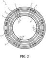
- FIG. 2 a schematic cross sectional front view of another assembly 1 in accordance with another embodiment of the invention can be seen.
- Fig. 2 shows a gradient coil 3 that comprises three coil winding layers which are embedded into a resin material 19 together with a cooling arrangement 2.
- This cooling arrangement 2 is comprised of second thermal connectors 5 which are fixed to different cooling tubes 4 thereby connecting the different cooling tubes 4 with each other in a thermally conducting manner.
- second thermal connectors 5 are fixed to different windings of one cooling tube 4 connecting these different windings of the cooling tube 4 in a thermally conducting manner. It should be noted that both possibilities can also be combined in one single embodiment.
- first thermal connectors 7 are provided which connect the cooling tubes 4 with the RF shield 6 in a thermally connecting manner.
- the embodiment of Fig. 2 relates to the embodiment shown in Fig. 1 .
- the first thermal connectors 7 do not go through the gradient coil 3. Instead, the first thermal connectors 7 are disposed at the longitudinal ends of the gradient coil 3 outside of the gradient coil 3.
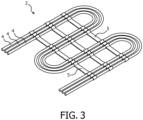
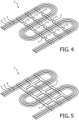
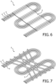
- Figs. 3 to 7 show perspective views of cooling tubes with second thermal connectors 7 according to different embodiments.
- the second thermal connectors 5 between the different cooling tubes 4 have a planar extension in the plane for disposing the cooling tubes 4.
- the second thermal connectors 7 connect the different cooling tubes 4 in order to allow heat transfer between the cooling tubes 4, in the arrangement of Fig. 4 the second thermal connectors 5 between the different cooling tubes 4 comprises cut-outs 12 in a longitudinal direction of the second thermal connector 5 thereby forming a cooling fins. In this way, heat which is transferred from the cooling tubes 4 into the second thermal connectors 5 can be dissipated into the surroundings of the gradient coil 3.
- Fig. 5 resembles the arrangement of Fig. 3 while the second thermal connectors 5 between the different cooling tubes 4 are connected with each other. This enhances efficient heat transfer and, thus, allows for a homogenous temperature distribution.
- a single second thermal connector 5 can be provided which covers a larger area and, thus, also allows for an efficient heat transfer, thereby providing effective cooling of the gradient coil 3.
- a plurality of second thermal connectors 5 is provided at least a part of the thermal connectors 5 between different cooling tubes 4 may be disposed in a staggered arrangement. Such a embodiment is shown in Fig. 7 .
- first thermal connectors 7 and/or the second thermal connectors 5 are preferably bonded and/or welded onto the cooling tube 4.
- the first thermal connectors 7 and/or the second thermal connectors 5 are preferably made from a flexible thermal conductor material.
- copper strap is used for the first thermal connectors 7 and the second thermal connectors 5, respectively. With such a copper strap for the first thermal connectors 7 and the second thermal connectors 5 a snug fit to the cooling tubes 4 can be achieved which further supports an efficient heat transfer from the cooling tubes 4 into the first thermal connectors 7 and the second thermal connectors 5, respectively.
- the invention is not restricted to metal as a material for the first thermal connectors 7 and the second thermal connectors 5.
- the first thermal connectors 7 and/or the second thermal connectors 5 are made from any material whose thermal conductive is higher than Epoxy, e.g., a thermally conductive ceramic material.
- cooling tubes 4 are looped with a second thermal connector 5. Therefore, according to this design, the part of the second thermal connector 5 which is fixed to the cooling tube 4 covers the cooling tube 4 circumferentially. This is preferably realized by using a flexible material for the second thermal connector 5. Further, this is not only a design option for the second thermal connector 5 but also for the the first thermal connector 7.
- Fig. 9 shows an embodiment according to which second thermal connectors 5 are welded onto metal rings 20.
- the metal rings 20 are welded or bonded to the cooling tubes 4.
- the present design can also be applied for the first thermal connectors 7.
- Fig. 10 is a representation of a metal layer shielded cooling tube 4 with an non-metallic insulation layer 21.
- the insulation layer 21 is partly peeled off for providing a welding spot 22 for fixing the first thermal connector 7 or a second thermal connector 5, respectively.
- the first thermal connector 7 or a second thermal connector 5, respectively is preferably made from a metallic flexible thermal conductor like a copper strap.
Landscapes
- Physics & Mathematics (AREA)
- Condensed Matter Physics & Semiconductors (AREA)
- General Physics & Mathematics (AREA)
- Health & Medical Sciences (AREA)
- Epidemiology (AREA)
- Magnetic Resonance Imaging Apparatus (AREA)
Claims (10)
- Ensemble pour un système d'imagerie par résonance magnétique, l'ensemble (1) comprenant un ensemble bobine de gradient avec au moins une bobine de gradient (3) et un blindage RF cylindrique (6) positionné radialement à l'intérieur de l'ensemble bobine de gradient, l'ensemble comprenant en outre un agencement de refroidissement (2) pour refroidir la bobine de gradient (3), dans lequel la bobine de gradient comprend trois couches d'enroulement de bobine qui sont intégrées dans un matériau de résine avec l'agencement de refroidissement, dans lequel l'ensemble bobine de gradient et chacune de ses couches d'enroulement présente une forme cylindrique,dans lequel l'agencement de refroidissement (2) comprend une pluralité de tubes de refroidissement (4) positionnés entre deux couches d'enroulement de l'ensemble bobine à gradient, et configurés pour transporter un fluide de refroidissement (9),caractérisé en ce que l'ensemble comprend en outre un agencement de connecteur thermique, dans lequelun premier connecteur thermique (7) est prévu entre chaque tube de refroidissement et le blindage RF, chaque premier connecteur thermique fournissant ainsi un pont thermique s'étendant radialement par la connexion thermique du tube de refroidissement (4) respectif au blindage RF (6).
- Ensemble selon la revendication 1, dans lequel chaque premier connecteur thermique (7) est disposé radialement dans l'ensemble à l'extérieur de la bobine de gradient (3) au niveau de ses deux extrémités longitudinales.
- Ensemble selon l'une quelconque des revendications précédentes, dans lequel chaque premier connecteur thermique (7) est lié et/ou soudé et/ou collé sur le tube de refroidissement (4) respectif.
- Ensemble selon l'une quelconque des revendications précédentes, dans lequel chaque premier connecteur thermique (7) est soudé sur un anneau s'enroulant autour du tube de refroidissement (4) respectif.
- Ensemble selon l'une quelconque des revendications précédentes, dans lequel chaque premier connecteur thermique (7) est réalisé à partir d'un matériau dont la conductivité thermique est supérieure à celle de l'époxy.
- Ensemble selon l'une quelconque des revendications précédentes, dans lequel chaque premier connecteur thermique (7) est réalisé à partir d'un matériau conducteur thermique flexible.
- Ensemble selon l'une quelconque des revendications précédentes, dans lequel chaque premier connecteur thermique (7) comprend une sangle en cuivre.
- Ensemble selon l'une des revendications 1 à 6, dans lequel les premiers connecteurs thermiques (7) sont réalisés à partir d'un matériau céramique thermoconducteur.
- Ensemble selon l'une quelconque des revendications précédentes, dans lequel la partie de chaque premier connecteur thermique (7), qui est fixée au tube de refroidissement (4) respectif, recouvre le tube de refroidissement de manière circonférentielle.
- Système d'imagerie par résonance magnétique avec un ensemble (1) selon l'une quelconque des revendications précédentes.
Applications Claiming Priority (3)
| Application Number | Priority Date | Filing Date | Title |
|---|---|---|---|
| CN2017074996 | 2017-02-27 | ||
| EP17167289.2A EP3392667A1 (fr) | 2017-04-20 | 2017-04-20 | Refroidissement d'une bobine de gradient d'un système d'imagerie par résonance magnétique |
| PCT/EP2018/054227 WO2018153889A1 (fr) | 2017-02-27 | 2018-02-21 | Refroidissement d'une bobine de gradient d'un système d'imagerie par résonance magnétique |
Publications (2)
| Publication Number | Publication Date |
|---|---|
| EP3586156A1 EP3586156A1 (fr) | 2020-01-01 |
| EP3586156B1 true EP3586156B1 (fr) | 2025-02-19 |
Family
ID=61599097
Family Applications (1)
| Application Number | Title | Priority Date | Filing Date |
|---|---|---|---|
| EP18709486.7A Active EP3586156B1 (fr) | 2017-02-27 | 2018-02-21 | Refroidissement d'une bobine de gradient d'un système d'imagerie par résonance magnétique |
Country Status (5)
| Country | Link |
|---|---|
| US (1) | US11002813B2 (fr) |
| EP (1) | EP3586156B1 (fr) |
| JP (1) | JP7177779B2 (fr) |
| CN (1) | CN110476074B (fr) |
| WO (1) | WO2018153889A1 (fr) |
Families Citing this family (4)
| Publication number | Priority date | Publication date | Assignee | Title |
|---|---|---|---|---|
| CN113050005B (zh) * | 2019-12-26 | 2024-01-30 | 西门子(深圳)磁共振有限公司 | 梯度线圈冷却部件及梯度线圈 |
| CN111665465B (zh) * | 2020-05-15 | 2022-09-23 | 宁波高思超导技术有限公司 | 一种无液氦超导磁体系统 |
| JP2024035534A (ja) * | 2022-09-02 | 2024-03-14 | 富士フイルムヘルスケア株式会社 | 磁気共鳴イメージング装置 |
| CN116068472B (zh) * | 2023-03-03 | 2023-06-06 | 山东奥新医疗科技有限公司 | 用于磁共振系统梯度系统的冷却系统及其制作方法 |
Family Cites Families (26)
| Publication number | Priority date | Publication date | Assignee | Title |
|---|---|---|---|---|
| JPH01113034A (ja) * | 1987-10-27 | 1989-05-01 | Yokogawa Medical Syst Ltd | 核磁気共鳴断層撮影装置の常電導電磁石 |
| DE19839987C2 (de) | 1998-09-02 | 2000-07-06 | Siemens Ag | Direktgekühlte Magnetspule, insbesondere Gradientenspule, sowie Verfahren zur Herstellung von Leitern dazu |
| WO2003093853A1 (fr) | 2002-05-02 | 2003-11-13 | Siemens Aktiengesellschaft | Systeme de bobines de gradient destine a un appareil d'imagerie par resonance magnetique |
| JP2005065752A (ja) * | 2003-08-28 | 2005-03-17 | Shin Etsu Chem Co Ltd | Mri用磁場発生装置 |
| US20050062473A1 (en) * | 2003-09-24 | 2005-03-24 | General Electric Company | Cryogen-free high temperature superconducting magnet with thermal reservoir |
| US7140420B2 (en) | 2003-11-05 | 2006-11-28 | General Electric Company | Thermal management apparatus and uses thereof |
| JP5100199B2 (ja) * | 2006-05-17 | 2012-12-19 | 株式会社東芝 | 傾斜磁場コイル、当該傾斜磁場コイルの製造方法、ならびに上記傾斜磁場コイルを備えた磁気共鳴イメージング装置 |
| DE102006034800B4 (de) | 2006-07-27 | 2010-04-08 | Siemens Ag | Verfahren zur Herstellung einer Kühleinrichtung für eine Gradientenspule, Kühleinrichtung für eine Gradientenspule, sowie Gradientenspule umfassend solche Kühleinrichtungen |
| DE102007008122B4 (de) * | 2007-02-19 | 2014-01-09 | Siemens Aktiengesellschaft | Anordnung zur Kühlung einer Gradientenspule |
| GB2470137B (en) | 2007-04-23 | 2011-08-10 | Gen Electric | System and apparatus for direct cooling of gradient coils |
| JP2009011476A (ja) * | 2007-07-03 | 2009-01-22 | Hitachi Medical Corp | 磁気共鳴イメージング装置 |
| US7812604B2 (en) | 2007-11-14 | 2010-10-12 | General Electric Company | Thermal management system for cooling a heat generating component of a magnetic resonance imaging apparatus |
| US7576542B1 (en) | 2008-06-26 | 2009-08-18 | General Electric Co. | System and apparatus for providing electrical and cooling interconnections in a magnetic resonance imaging (MRI) system |
| JP5597351B2 (ja) * | 2008-10-07 | 2014-10-01 | 株式会社東芝 | 磁場発生コイル装置 |
| US8253416B2 (en) * | 2009-03-10 | 2012-08-28 | Time Medical Holdings Company Limited | Superconductor magnetic resonance imaging system and method (super-MRI) |
| US8188742B2 (en) * | 2009-07-31 | 2012-05-29 | General Electric Company | System and method for thermo-electric cooling of RF coils in an MR imaging system |
| JP2011087904A (ja) | 2009-09-28 | 2011-05-06 | Toshiba Corp | 磁気共鳴イメージング装置 |
| DE102010015631B4 (de) | 2010-04-20 | 2012-09-27 | Siemens Aktiengesellschaft | Gradientenspulenanordnung und Herstellungsverfahren |
| US8374663B2 (en) * | 2011-01-31 | 2013-02-12 | General Electric Company | Cooling system and method for cooling superconducting magnet devices |
| DE102011082352A1 (de) * | 2011-09-08 | 2013-03-14 | Siemens Aktiengesellschaft | Vorrichtung und Verfahren zum Kühlen einer Einrichtung |
| DE102011083204B4 (de) | 2011-09-22 | 2018-12-20 | Siemens Healthcare Gmbh | Kühleinrichtung für eine Gradientenspule und deren Verwendung |
| US20130184559A1 (en) * | 2012-01-12 | 2013-07-18 | Siemens Medical Solutions Usa, Inc. | Magnetic Resonance Imaging Compatible Positron Emission Tomography Detector |
| JP5887261B2 (ja) * | 2012-12-25 | 2016-03-16 | 株式会社日立メディコ | 傾斜磁場コイル装置及び磁気共鳴イメージング装置 |
| US10126389B2 (en) | 2013-04-05 | 2018-11-13 | Koninklijke Philips N.V. | Gradient coil assembly with outer coils comprising aluminum |
| JP6462292B2 (ja) * | 2014-09-26 | 2019-01-30 | キヤノンメディカルシステムズ株式会社 | 磁気共鳴イメージング装置 |
| CN205102487U (zh) * | 2015-11-16 | 2016-03-23 | 蒋沈军 | 一种用于磁共振设备的冷却装置 |
-
2018
- 2018-02-21 JP JP2019546151A patent/JP7177779B2/ja active Active
- 2018-02-21 WO PCT/EP2018/054227 patent/WO2018153889A1/fr not_active Ceased
- 2018-02-21 EP EP18709486.7A patent/EP3586156B1/fr active Active
- 2018-02-21 CN CN201880022288.9A patent/CN110476074B/zh active Active
- 2018-02-21 US US16/487,489 patent/US11002813B2/en active Active
Also Published As
| Publication number | Publication date |
|---|---|
| US20200057127A1 (en) | 2020-02-20 |
| WO2018153889A1 (fr) | 2018-08-30 |
| EP3586156A1 (fr) | 2020-01-01 |
| JP7177779B2 (ja) | 2022-11-24 |
| CN110476074A (zh) | 2019-11-19 |
| CN110476074B (zh) | 2023-07-14 |
| JP2020508754A (ja) | 2020-03-26 |
| US11002813B2 (en) | 2021-05-11 |
Similar Documents
| Publication | Publication Date | Title |
|---|---|---|
| EP3586156B1 (fr) | Refroidissement d'une bobine de gradient d'un système d'imagerie par résonance magnétique | |
| CN1763558B (zh) | 在磁共振成像设备中提供射频屏蔽件的梯度孔冷却 | |
| JP5226930B2 (ja) | 熱管理機器及びその製造方法 | |
| EP2981978B1 (fr) | Ensemble de bobines de gradient possédant des bobines externes comprenant de l'aluminium | |
| CN109564809B (zh) | 带有热辐射屏的磁体系统 | |
| EP3392667A1 (fr) | Refroidissement d'une bobine de gradient d'un système d'imagerie par résonance magnétique | |
| JP7232197B2 (ja) | 磁気共鳴撮像システムの傾斜磁場コイルの冷却 | |
| CN114420414B (zh) | 一种快速散热线圈 | |
| EP3608929B1 (fr) | Moyen conducteur multifilaments refroidissable directement | |
| JP5222735B2 (ja) | 磁気共鳴イメージング装置および傾斜磁場コイル | |
| US11531077B2 (en) | Cooling structure of gradient coil having flexible coolant pipelines | |
| JP2011131009A (ja) | 磁気共鳴イメージング装置 | |
| CN214375220U (zh) | 用于核磁共振成像系统的巴伦组件和电缆组件 | |
| EP4682570A1 (fr) | Supports de refroidissement pour aimants supraconducteurs et dispositif d'imagerie par résonance magnétique ayant les supports de refroidissement | |
| JP2005353931A (ja) | 超電導コイルの伝熱構造及び超電導マグネット | |
| JP2024508859A (ja) | シールド付き勾配アセンブリ | |
| JPH04367650A (ja) | 磁気共鳴イメージング装置 | |
| CN117015717A (zh) | 屏蔽梯度组件 |
Legal Events
| Date | Code | Title | Description |
|---|---|---|---|
| STAA | Information on the status of an ep patent application or granted ep patent |
Free format text: STATUS: UNKNOWN |
|
| STAA | Information on the status of an ep patent application or granted ep patent |
Free format text: STATUS: THE INTERNATIONAL PUBLICATION HAS BEEN MADE |
|
| PUAI | Public reference made under article 153(3) epc to a published international application that has entered the european phase |
Free format text: ORIGINAL CODE: 0009012 |
|
| STAA | Information on the status of an ep patent application or granted ep patent |
Free format text: STATUS: REQUEST FOR EXAMINATION WAS MADE |
|
| 17P | Request for examination filed |
Effective date: 20190927 |
|
| AK | Designated contracting states |
Kind code of ref document: A1 Designated state(s): AL AT BE BG CH CY CZ DE DK EE ES FI FR GB GR HR HU IE IS IT LI LT LU LV MC MK MT NL NO PL PT RO RS SE SI SK SM TR |
|
| AX | Request for extension of the european patent |
Extension state: BA ME |
|
| RAP1 | Party data changed (applicant data changed or rights of an application transferred) |
Owner name: KONINKLIJKE PHILIPS N.V. |
|
| DAV | Request for validation of the european patent (deleted) | ||
| DAX | Request for extension of the european patent (deleted) | ||
| STAA | Information on the status of an ep patent application or granted ep patent |
Free format text: STATUS: EXAMINATION IS IN PROGRESS |
|
| 17Q | First examination report despatched |
Effective date: 20221116 |
|
| GRAP | Despatch of communication of intention to grant a patent |
Free format text: ORIGINAL CODE: EPIDOSNIGR1 |
|
| STAA | Information on the status of an ep patent application or granted ep patent |
Free format text: STATUS: GRANT OF PATENT IS INTENDED |
|
| INTG | Intention to grant announced |
Effective date: 20240920 |
|
| GRAS | Grant fee paid |
Free format text: ORIGINAL CODE: EPIDOSNIGR3 |
|
| GRAA | (expected) grant |
Free format text: ORIGINAL CODE: 0009210 |
|
| STAA | Information on the status of an ep patent application or granted ep patent |
Free format text: STATUS: THE PATENT HAS BEEN GRANTED |
|
| AK | Designated contracting states |
Kind code of ref document: B1 Designated state(s): AL AT BE BG CH CY CZ DE DK EE ES FI FR GB GR HR HU IE IS IT LI LT LU LV MC MK MT NL NO PL PT RO RS SE SI SK SM TR |
|
| REG | Reference to a national code |
Ref country code: GB Ref legal event code: FG4D |
|
| REG | Reference to a national code |
Ref country code: CH Ref legal event code: EP |
|
| REG | Reference to a national code |
Ref country code: IE Ref legal event code: FG4D |
|
| REG | Reference to a national code |
Ref country code: DE Ref legal event code: R096 Ref document number: 602018079290 Country of ref document: DE |
|
| REG | Reference to a national code |
Ref country code: DE Ref legal event code: R084 Ref document number: 602018079290 Country of ref document: DE |
|
| REG | Reference to a national code |
Ref country code: GB Ref legal event code: 746 Effective date: 20250408 |
|
| REG | Reference to a national code |
Ref country code: NL Ref legal event code: MP Effective date: 20250219 |
|
| PG25 | Lapsed in a contracting state [announced via postgrant information from national office to epo] |
Ref country code: RS Free format text: LAPSE BECAUSE OF FAILURE TO SUBMIT A TRANSLATION OF THE DESCRIPTION OR TO PAY THE FEE WITHIN THE PRESCRIBED TIME-LIMIT Effective date: 20250519 |
|
| PG25 | Lapsed in a contracting state [announced via postgrant information from national office to epo] |
Ref country code: FI Free format text: LAPSE BECAUSE OF FAILURE TO SUBMIT A TRANSLATION OF THE DESCRIPTION OR TO PAY THE FEE WITHIN THE PRESCRIBED TIME-LIMIT Effective date: 20250219 |
|
| PG25 | Lapsed in a contracting state [announced via postgrant information from national office to epo] |
Ref country code: PL Free format text: LAPSE BECAUSE OF FAILURE TO SUBMIT A TRANSLATION OF THE DESCRIPTION OR TO PAY THE FEE WITHIN THE PRESCRIBED TIME-LIMIT Effective date: 20250219 |
|
| PG25 | Lapsed in a contracting state [announced via postgrant information from national office to epo] |
Ref country code: ES Free format text: LAPSE BECAUSE OF FAILURE TO SUBMIT A TRANSLATION OF THE DESCRIPTION OR TO PAY THE FEE WITHIN THE PRESCRIBED TIME-LIMIT Effective date: 20250219 |
|
| REG | Reference to a national code |
Ref country code: LT Ref legal event code: MG9D |
|
| PG25 | Lapsed in a contracting state [announced via postgrant information from national office to epo] |
Ref country code: NO Free format text: LAPSE BECAUSE OF FAILURE TO SUBMIT A TRANSLATION OF THE DESCRIPTION OR TO PAY THE FEE WITHIN THE PRESCRIBED TIME-LIMIT Effective date: 20250519 Ref country code: IS Free format text: LAPSE BECAUSE OF FAILURE TO SUBMIT A TRANSLATION OF THE DESCRIPTION OR TO PAY THE FEE WITHIN THE PRESCRIBED TIME-LIMIT Effective date: 20250619 |
|
| PG25 | Lapsed in a contracting state [announced via postgrant information from national office to epo] |
Ref country code: NL Free format text: LAPSE BECAUSE OF FAILURE TO SUBMIT A TRANSLATION OF THE DESCRIPTION OR TO PAY THE FEE WITHIN THE PRESCRIBED TIME-LIMIT Effective date: 20250219 |
|
| PG25 | Lapsed in a contracting state [announced via postgrant information from national office to epo] |
Ref country code: HR Free format text: LAPSE BECAUSE OF FAILURE TO SUBMIT A TRANSLATION OF THE DESCRIPTION OR TO PAY THE FEE WITHIN THE PRESCRIBED TIME-LIMIT Effective date: 20250219 |
|
| PG25 | Lapsed in a contracting state [announced via postgrant information from national office to epo] |
Ref country code: PT Free format text: LAPSE BECAUSE OF FAILURE TO SUBMIT A TRANSLATION OF THE DESCRIPTION OR TO PAY THE FEE WITHIN THE PRESCRIBED TIME-LIMIT Effective date: 20250620 Ref country code: LV Free format text: LAPSE BECAUSE OF FAILURE TO SUBMIT A TRANSLATION OF THE DESCRIPTION OR TO PAY THE FEE WITHIN THE PRESCRIBED TIME-LIMIT Effective date: 20250219 |
|
| PG25 | Lapsed in a contracting state [announced via postgrant information from national office to epo] |
Ref country code: GR Free format text: LAPSE BECAUSE OF FAILURE TO SUBMIT A TRANSLATION OF THE DESCRIPTION OR TO PAY THE FEE WITHIN THE PRESCRIBED TIME-LIMIT Effective date: 20250520 Ref country code: BG Free format text: LAPSE BECAUSE OF FAILURE TO SUBMIT A TRANSLATION OF THE DESCRIPTION OR TO PAY THE FEE WITHIN THE PRESCRIBED TIME-LIMIT Effective date: 20250219 |
|
| REG | Reference to a national code |
Ref country code: AT Ref legal event code: MK05 Ref document number: 1768748 Country of ref document: AT Kind code of ref document: T Effective date: 20250219 |
|
| PG25 | Lapsed in a contracting state [announced via postgrant information from national office to epo] |
Ref country code: SE Free format text: LAPSE BECAUSE OF FAILURE TO SUBMIT A TRANSLATION OF THE DESCRIPTION OR TO PAY THE FEE WITHIN THE PRESCRIBED TIME-LIMIT Effective date: 20250219 |
|
| REG | Reference to a national code |
Ref country code: CH Ref legal event code: PL |
|
| PG25 | Lapsed in a contracting state [announced via postgrant information from national office to epo] |
Ref country code: SM Free format text: LAPSE BECAUSE OF FAILURE TO SUBMIT A TRANSLATION OF THE DESCRIPTION OR TO PAY THE FEE WITHIN THE PRESCRIBED TIME-LIMIT Effective date: 20250219 |
|
| PG25 | Lapsed in a contracting state [announced via postgrant information from national office to epo] |
Ref country code: DK Free format text: LAPSE BECAUSE OF FAILURE TO SUBMIT A TRANSLATION OF THE DESCRIPTION OR TO PAY THE FEE WITHIN THE PRESCRIBED TIME-LIMIT Effective date: 20250219 |
|
| PG25 | Lapsed in a contracting state [announced via postgrant information from national office to epo] |
Ref country code: IT Free format text: LAPSE BECAUSE OF FAILURE TO SUBMIT A TRANSLATION OF THE DESCRIPTION OR TO PAY THE FEE WITHIN THE PRESCRIBED TIME-LIMIT Effective date: 20250219 Ref country code: LU Free format text: LAPSE BECAUSE OF NON-PAYMENT OF DUE FEES Effective date: 20250221 |
|
| PG25 | Lapsed in a contracting state [announced via postgrant information from national office to epo] |
Ref country code: AT Free format text: LAPSE BECAUSE OF FAILURE TO SUBMIT A TRANSLATION OF THE DESCRIPTION OR TO PAY THE FEE WITHIN THE PRESCRIBED TIME-LIMIT Effective date: 20250219 |
|
| PG25 | Lapsed in a contracting state [announced via postgrant information from national office to epo] |
Ref country code: CH Free format text: LAPSE BECAUSE OF NON-PAYMENT OF DUE FEES Effective date: 20250228 |
|
| PG25 | Lapsed in a contracting state [announced via postgrant information from national office to epo] |
Ref country code: EE Free format text: LAPSE BECAUSE OF FAILURE TO SUBMIT A TRANSLATION OF THE DESCRIPTION OR TO PAY THE FEE WITHIN THE PRESCRIBED TIME-LIMIT Effective date: 20250219 Ref country code: CZ Free format text: LAPSE BECAUSE OF FAILURE TO SUBMIT A TRANSLATION OF THE DESCRIPTION OR TO PAY THE FEE WITHIN THE PRESCRIBED TIME-LIMIT Effective date: 20250219 |
|
| PG25 | Lapsed in a contracting state [announced via postgrant information from national office to epo] |
Ref country code: RO Free format text: LAPSE BECAUSE OF FAILURE TO SUBMIT A TRANSLATION OF THE DESCRIPTION OR TO PAY THE FEE WITHIN THE PRESCRIBED TIME-LIMIT Effective date: 20250219 |
|
| PG25 | Lapsed in a contracting state [announced via postgrant information from national office to epo] |
Ref country code: SK Free format text: LAPSE BECAUSE OF FAILURE TO SUBMIT A TRANSLATION OF THE DESCRIPTION OR TO PAY THE FEE WITHIN THE PRESCRIBED TIME-LIMIT Effective date: 20250219 |
|
| REG | Reference to a national code |
Ref country code: DE Ref legal event code: R097 Ref document number: 602018079290 Country of ref document: DE |
|
| REG | Reference to a national code |
Ref country code: BE Ref legal event code: MM Effective date: 20250228 |
|
| PG25 | Lapsed in a contracting state [announced via postgrant information from national office to epo] |
Ref country code: MC Free format text: LAPSE BECAUSE OF FAILURE TO SUBMIT A TRANSLATION OF THE DESCRIPTION OR TO PAY THE FEE WITHIN THE PRESCRIBED TIME-LIMIT Effective date: 20250219 |
|
| PLBE | No opposition filed within time limit |
Free format text: ORIGINAL CODE: 0009261 |
|
| STAA | Information on the status of an ep patent application or granted ep patent |
Free format text: STATUS: NO OPPOSITION FILED WITHIN TIME LIMIT |
|
| PG25 | Lapsed in a contracting state [announced via postgrant information from national office to epo] |
Ref country code: FR Free format text: LAPSE BECAUSE OF NON-PAYMENT OF DUE FEES Effective date: 20250419 |
|
| PG25 | Lapsed in a contracting state [announced via postgrant information from national office to epo] |
Ref country code: BE Free format text: LAPSE BECAUSE OF NON-PAYMENT OF DUE FEES Effective date: 20250228 |
|
| PG25 | Lapsed in a contracting state [announced via postgrant information from national office to epo] |
Ref country code: IE Free format text: LAPSE BECAUSE OF NON-PAYMENT OF DUE FEES Effective date: 20250221 |
|
| 26N | No opposition filed |
Effective date: 20251120 |
|
| PGFP | Annual fee paid to national office [announced via postgrant information from national office to epo] |
Ref country code: GB Payment date: 20260223 Year of fee payment: 9 |
|
| PGFP | Annual fee paid to national office [announced via postgrant information from national office to epo] |
Ref country code: DE Payment date: 20260220 Year of fee payment: 9 |