EP3587055A1 - Manipulateur et robot mobile - Google Patents
Manipulateur et robot mobile Download PDFInfo
- Publication number
- EP3587055A1 EP3587055A1 EP19170239.8A EP19170239A EP3587055A1 EP 3587055 A1 EP3587055 A1 EP 3587055A1 EP 19170239 A EP19170239 A EP 19170239A EP 3587055 A1 EP3587055 A1 EP 3587055A1
- Authority
- EP
- European Patent Office
- Prior art keywords
- light
- link
- distance
- distance sensor
- manipulator
- Prior art date
- Legal status (The legal status is an assumption and is not a legal conclusion. Google has not performed a legal analysis and makes no representation as to the accuracy of the status listed.)
- Granted
Links
Images


Classifications
-
- B—PERFORMING OPERATIONS; TRANSPORTING
- B25—HAND TOOLS; PORTABLE POWER-DRIVEN TOOLS; MANIPULATORS
- B25J—MANIPULATORS; CHAMBERS PROVIDED WITH MANIPULATION DEVICES
- B25J9/00—Program-controlled manipulators
- B25J9/16—Program controls
- B25J9/1674—Program controls characterised by safety, monitoring, diagnostic
-
- B—PERFORMING OPERATIONS; TRANSPORTING
- B25—HAND TOOLS; PORTABLE POWER-DRIVEN TOOLS; MANIPULATORS
- B25J—MANIPULATORS; CHAMBERS PROVIDED WITH MANIPULATION DEVICES
- B25J19/00—Accessories fitted to manipulators, e.g. for monitoring, for viewing; Safety devices combined with or specially adapted for use in connection with manipulators
- B25J19/06—Safety devices
-
- B—PERFORMING OPERATIONS; TRANSPORTING
- B25—HAND TOOLS; PORTABLE POWER-DRIVEN TOOLS; MANIPULATORS
- B25J—MANIPULATORS; CHAMBERS PROVIDED WITH MANIPULATION DEVICES
- B25J13/00—Controls for manipulators
- B25J13/08—Controls for manipulators by means of sensing devices, e.g. viewing or touching devices
- B25J13/086—Proximity sensors
-
- B—PERFORMING OPERATIONS; TRANSPORTING
- B25—HAND TOOLS; PORTABLE POWER-DRIVEN TOOLS; MANIPULATORS
- B25J—MANIPULATORS; CHAMBERS PROVIDED WITH MANIPULATION DEVICES
- B25J19/00—Accessories fitted to manipulators, e.g. for monitoring, for viewing; Safety devices combined with or specially adapted for use in connection with manipulators
- B25J19/02—Sensing devices
-
- B—PERFORMING OPERATIONS; TRANSPORTING
- B25—HAND TOOLS; PORTABLE POWER-DRIVEN TOOLS; MANIPULATORS
- B25J—MANIPULATORS; CHAMBERS PROVIDED WITH MANIPULATION DEVICES
- B25J19/00—Accessories fitted to manipulators, e.g. for monitoring, for viewing; Safety devices combined with or specially adapted for use in connection with manipulators
- B25J19/02—Sensing devices
- B25J19/021—Optical sensing devices
-
- B—PERFORMING OPERATIONS; TRANSPORTING
- B25—HAND TOOLS; PORTABLE POWER-DRIVEN TOOLS; MANIPULATORS
- B25J—MANIPULATORS; CHAMBERS PROVIDED WITH MANIPULATION DEVICES
- B25J19/00—Accessories fitted to manipulators, e.g. for monitoring, for viewing; Safety devices combined with or specially adapted for use in connection with manipulators
- B25J19/02—Sensing devices
- B25J19/021—Optical sensing devices
- B25J19/022—Optical sensing devices using lasers
-
- B—PERFORMING OPERATIONS; TRANSPORTING
- B25—HAND TOOLS; PORTABLE POWER-DRIVEN TOOLS; MANIPULATORS
- B25J—MANIPULATORS; CHAMBERS PROVIDED WITH MANIPULATION DEVICES
- B25J9/00—Program-controlled manipulators
- B25J9/16—Program controls
-
- B—PERFORMING OPERATIONS; TRANSPORTING
- B25—HAND TOOLS; PORTABLE POWER-DRIVEN TOOLS; MANIPULATORS
- B25J—MANIPULATORS; CHAMBERS PROVIDED WITH MANIPULATION DEVICES
- B25J9/00—Program-controlled manipulators
- B25J9/16—Program controls
- B25J9/1612—Program controls characterised by the hand, wrist, grip control
-
- B—PERFORMING OPERATIONS; TRANSPORTING
- B25—HAND TOOLS; PORTABLE POWER-DRIVEN TOOLS; MANIPULATORS
- B25J—MANIPULATORS; CHAMBERS PROVIDED WITH MANIPULATION DEVICES
- B25J9/00—Program-controlled manipulators
- B25J9/16—Program controls
- B25J9/1674—Program controls characterised by safety, monitoring, diagnostic
- B25J9/1676—Avoiding collision or forbidden zones
-
- B—PERFORMING OPERATIONS; TRANSPORTING
- B25—HAND TOOLS; PORTABLE POWER-DRIVEN TOOLS; MANIPULATORS
- B25J—MANIPULATORS; CHAMBERS PROVIDED WITH MANIPULATION DEVICES
- B25J9/00—Program-controlled manipulators
- B25J9/16—Program controls
- B25J9/1679—Program controls characterised by the tasks executed
Definitions
- the present disclosure relates to a manipulator and a moving robot.
- the related art is excellent for detecting an obstacle approaching an entire operation space of a manipulator, it is not suitable for the purpose of individually monitoring a local operation space of each link. It is possible to analyze images which can be obtained by a camera in order to detect an obstacle including the local operation space. However, there are problems that a load of analysis processing increases or an operation space that becomes a blind spot is generated.
- the present disclosure provides a manipulator capable of accurately monitoring an obstacle entering in an operation space of each link with a simpler sensor configuration and a moving robot including the manipulator.
- a first exemplary aspect is a manipulator, including: a link; a joint unit configured to rotate the link; and a distance sensor configured to detect an obstacle entering in a monitoring space that is determined so as to include at least a rotating direction side of the link, the distance sensor being installed so that a sensing direction faces a direction parallel to a surface of the link.
- the distance sensor is preferably installed so that the sensing direction corresponds to a longitudinal direction of the link.
- the distance sensor is preferably installed at an end of the link. If it is installed at the end of the link, a space that becomes a blind spot for the distance sensor can be reduced.
- the distance sensor preferably includes: a light emitting unit configured to emit a modulated projection light; and a light receiving unit configured to receive the projection light reflected by the obstacle.
- the distance sensor having such a configuration can calculate a distance measurement result with a relatively simple circuit configuration, and thus it is suitable when a large number of distance sensors are installed.
- the one distance sensor be installed for each of the rotating links and the respective projection lights of the distance sensors be modulated so as to differ from each other.
- the one distance sensor is installed for each of the links, there is a possibility of a projection light from a distance sensor installed in one link reaching the light receiving unit of a distance sensor installed in another link. Such a case causes an error detection.
- the respective projection lights of the distance sensors are modulated so as to differ from each other, it is possible to prevent such an error detection by checking a correlation between the projection light and the reflected light.
- the distance sensor is preferably a sensor of the triangular distance measurement system.
- the sensor of the triangular distance measurement system may detect a position of the reflected light, and thus a sensor configuration can be simple.
- the projection light of the distance sensor is preferably an infrared light. If an infrared radiation is used as the projection light, it does not bother workers working in the surrounding area.
- a plurality of distance sensors may be used to detect an obstacle entering in one monitoring space.
- a size of the monitoring space can be expanded in accordance with the specification.
- the respective projection lights of the distance sensors be modulated so as to differ from each other.
- the respective projection lights of the distance sensors are modulated so as to differ from each other, it is possible to prevent such error detection by checking a correlation between the projection light and the reflected light.
- Another exemplary aspect is a moving robot including the aforementioned manipulator. Since a sensor configuration for monitoring a local monitoring space set in each link does not affect a space recognition in a movement operation of the moving robot, this configuration is convenient when the operations of the manipulator and the moving robot are performed simultaneously.
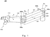
- Fig. 1 is an external perspective view of a manipulator 100 according to this embodiment.
- the manipulator 100 mainly includes joint units (a first joint unit 111, a second joint unit 112, and a third joint unit 113), links (a first link 121 and a second link 122), a hand 110, and distance sensors (an L 1 distance sensor 200a, a R 1 distance sensor 200b, an L 2 distance sensor 200c, and a R 2 distance sensor 200d).
- the first joint unit 111 supported by a base incorporates a motor for rotating the first link 121 around a rotating shaft Ax 1 and also supports the first link 121 in a rotatable manner.
- the first link 121 has a box shape extending from the first joint 111 in a radiation direction with respect to the rotating shaft Ax 1 as a longitudinal direction thereof, and supports the second joint 112 at a tip thereof.
- the second joint unit 112 incorporates a motor for rotating the second link 122 around a rotating shaft Ax 2 and also supports the second link 122 in a rotatable manner.
- the second link 122 has a box shape extending from the second joint 112 in a radiation direction with respect to the rotating shaft Ax 2 as a longitudinal direction thereof, and supports the third joint 113 at the tip thereof.
- the third joint 113 incorporates a motor for achieving a grasping motion in which the hand 110 grasps a target object, and also supports the hand 110 in a rotatable manner.
- Monitoring spaces SR for monitoring an entry of an obstacle are respectively set on the rotating direction sides of the first and second links 121 and 122.
- the monitoring space SR set on the counterclockwise rotating direction side of the first link 121 is indicated by a substantially rectangular parallelepiped space surrounded by a dotted line as shown in Fig. 1 .
- the L 1 distance sensor 200a monitors this monitoring space SR surrounded by a dotted line and detects an obstacle entering therein.
- a sensing region in which the L 1 distance sensor 200a can detect the obstacle includes the monitoring space SR.
- the L 1 distance sensor 200a is installed in the vicinity of a base end part of the first link 121 and on the counterclockwise rotating direction side.
- the L 1 distance sensor 200a is a sensor of the triangular distance measurement system that detects a distance to an obstacle by collecting, with a condenser lens, the reflected light in which the projection light projected toward the monitoring space SR through a projection lens 221 is reflected by the obstacle and returned.
- the L 1 distance sensor 200a is installed so that the projection direction of the projection light faces a direction parallel to a surface of the first link 121. That is, the L 1 distance sensor 200a is installed so that the sensing direction corresponds to the longitudinal direction of the first link 121.
- the first link 121 has a box shape, it is not necessary for the link surface to be a plane. It can be considered that since the projection direction of the projection light is a direction parallel to the link surface, the projection direction of the projection light is a direction orthogonal to a moving direction of the link.
- the R 1 distance sensor 200b, the L 2 distance sensor 200c, and the R 2 distance sensor 200d are the same distance sensors of the triangular distance measurement system as the L 1 distance sensor 200a.
- the R 1 distance sensor 200b is installed in the vicinity of the base end part of the first link 121 on the clockwise rotating direction side thereof.
- the L 2 distance sensor 200c is installed in the vicinity of a base end part of the second link 122 on the counterclockwise rotating direction side thereof
- the R 2 distance sensor 200d is installed in the vicinity of the base end part of the second link 122 on the clockwise rotating direction side thereof.
- the distance sensors are respectively installed so that the projection direction of the projection light faces a direction parallel to each surface of the links, and monitor the monitoring space SR set on the rotating direction side and detects an obstacle entering therein.
- the distance sensors respectively transmit a detection result to a control unit (not shown) when detecting an obstacle entering in the monitoring space.
- the control unit stops a rotating operation or maintains a grasping state in accordance with the detection result.
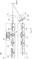
- Fig. 2 is a block diagram showing a configuration of the distance sensor 200.
- the distance sensor 200 includes a transmission side circuit Tc that generates a projection light for measuring a distance, and a receiving side circuit Rc that performs various processes by receiving a reflected light in which the projection light is reflected by an obstacle and returned.
- the distance sensor 200 measures a distance to the obstacle by the projection light using an IR light in the triangular distance measurement system.
- the projection light is projected from a light-emitting device 207 which is, for example, an infrared LED outputting the IR light.
- the projection light projected from the light-emitting device 207 is converted into a substantially parallel light by the projection lens 221, which is emitted to the monitoring space SR.
- a PN code generation cycle generating unit 202 generates a cycle signal to generate a PN code and transfers the generated cycle signal to a PN code generating unit 204.
- the PN code generating unit 204 generates a PN code by using the cycle signal received from the PN code generation cycle generating unit 202 as a trigger and transfers the generated PN code to a superimposing unit 205.
- the PN code includes a pseudo noise (PN) signal.
- the PN code generating unit 204 includes a logic circuit which is composed of an n-bit shift register and one or more half-adders, for generating the M sequence.
- the M sequence is a code string having a cycle (bit length) of 2 n-1.
- the 127-bit M sequence of n 7 as shown in Fig. 3 , for example.
- a transmission carrier cycle generating unit 203 generates a carrier frequency having a constant frequency and transfers the generated carrier frequency to the superimposing unit 205.
- the superimposing unit 205 superimposes the PN code received from the PN code generating unit 204 on the carrier frequency received from the transmission carrier cycle generating unit 203 to generate a light-emitting pattern, and then transfers the generated light-emitting pattern to a transmission unit 206.
- the transmission unit 206 blinks the light-emitting device 7 in accordance with the light-emitting pattern received from the superimposing unit 205 to make the light-emitting device 7 project a projection light.
- a reflected light is not returned. Even when a reflected light is returned from outside the monitoring space SR, a light-receiving device 208 does not receive the reflected light. Alternatively, even when it receives the reflected light, error processing is performed by a circuit at the subsequent stage.
- the projection light reflected by the obstacle is collected by a condenser lens 222.
- the collected projection light passes through an IR filter 223 which makes an infrared light selectively pass therethrough, and then reaches the light-receiving device 208.
- the light-receiving device 208 is, for example, a PSD (Position Sensitive Detector) device, and a photodiode corresponding to a distance to the obstacle detects the reflected light.
- An output from the light-receiving device 208 is transmitted to a reception unit 209 as a light-receiving pattern including light-receiving position information.
- the reception unit 209 converts the received light-receiving pattern into a reception signal and transfers the reception signal to a correlation calculation unit 210.
- the correlation calculation unit 210 calculates a correlation between the light-receiving pattern of the reception signal received from the reception unit 209 and the light-emitting pattern generated by the superimposing unit 205. Specifically, the correlation calculation unit 210 calculates a coincidence degree indicating a degree of coincidence between the light-emitting pattern and the light-receiving pattern.
- Fig. 4 is a diagram showing timings at which a correlation calculation is performed.
- the coincidence degree is calculated by comparing the blinking pattern of the light-emitting pattern with the light-receiving pattern for each bit of the predetermined correlation calculation timings. For example, when a 7-bit shift register is used, blinks in which the light-emitting pattern and the light-receiving pattern coincide are counted for each of the 127 correlation operation timings. In the case of the blink in which the light-emitting pattern and the light-receiving pattern coincide, a counter C is incremented, and in the case of the blink in which the light-emitting pattern and the light-receiving pattern do not coincide, the counter C remains unchanged.
- the counter C indicates 127.
- the coincidence degree is a value obtained by dividing the counter C by 127, and when this value is equal to or larger than a predetermined threshold value, the correlation calculation unit 210 determines that the reflected light is a reflected light in which the projection light projected from the light-emitting device 207 is returned. On the other hand, when the coincidence degree is smaller than the predetermined threshold value, the correlation calculation unit 210 determines that the reflected light is an incident light which does not result from the projection light projected from the light-emitting device 207.
- a distance calculation unit 211 calculates a distance when the coincidence degree is equal to or larger than the predetermined threshold value.
- the distance calculation unit 211 uses the light-receiving position information of the light-receiving device 208 to calculate a distance to an obstacle based on the principle of the triangular distance measurement, and transfers the calculated distance to an output unit 212. Note that when the light-receiving device 208 does not receive a reflected light, or when the incident light in which the coincidence degree is less than the predetermined threshold value is received, the distance calculation unit 211 transfers a signal indicating that there is no obstacle to the output unit 212.
- the output unit 212 outputs a detection result showing that there is no distance calculated by the distance calculation unit 211 or there is no obstacle to the control unit (not shown). The control unit controls the manipulator 100 in accordance with this detection result.
- the manipulator 100 includes four such distance sensors 200 (the L 1 distance sensor 200a, the R 1 distance sensor 200b, the L 2 distance sensor 200c, and the R 2 distance sensor 200d) as described above.
- the respective distance sensors use a PN code different from each other, and thus the light-emitting pattern thereof differs from each other. That is, the respective projection lights of the distance sensors are modulated so as to differ from each other. Accordingly, even when a light reflected by a projection light from a distance sensor accidentally reaches the light-receiving unit of another distance sensor, the coincidence degree calculated by the correlation calculation unit 210 becomes small, and thus it is not erroneously determined that there is an obstacle. Further, the distance sensor 200 uses the infrared light, which is invisible, and thus it does not bother workers working in the surrounding area.
- Fig. 5 is the flowchart showing processes of the distance measurement.
- Step S100 The PN code generating unit 204 generates a PN code based on the PN code cycle generated by the PN code generation cycle generating unit 202.
- Step S101 the superimposing unit 205 superimposes the PN code and the carrier frequency generated by the transmission carrier cycle generating unit 203 to generate a light-emitting pattern.
- Step S102 the transmission unit 206 blinks the light-emitting device 207 according to the light-emitting pattern to make it project a projection light.
- Step S103 when having received the light-receiving pattern from the light-receiving device 208, the reception unit 209 converts the received light-receiving pattern into a reception signal and transfer the reception signal to the correlation calculation unit 210.
- the process proceeds to Step S104.
- the process proceeds to Step S108.
- Step S104 the correlation calculation unit 210 calculates a coincidence degree from the light-receiving pattern of the reception signal and the light-emitting pattern generated by the superimposing unit 205. Then, the process proceeds to Step S105, and it is determined whether the coincidence degree is equal to or larger than a predetermined threshold value. When the coincidence degree is equal to or larger than the predetermined threshold value, the process proceeds to Step S106, and when the coincidence degree is less than the predetermined threshold value, the process proceeds to Step S108.
- Step S107 the distance calculation unit 211 uses the light-receiving position information of the light-receiving device 208 to calculate a distance to an obstacle based on the principle of the triangular distance measurement, and transfers the calculated distance to the output unit 212. Then, the output unit 212 outputs the distance calculated by the distance calculation unit 211 as a detection result to the control unit. Then, the process proceeds to Step S109.
- Step S109 when a stop command is received, each block of the distance sensors 200 stops the function thereof and ends the series of processes. When the stop command is not received, the process returns to Step S102 and the series of processes is repeated. Note that the processes in Step S102 to Step S108 are repeated, for example, at a cycle of 10 msec.
- Fig. 6 is an external perspective view of a manipulator 101 which is a modified example of the manipulator 100.
- the manipulator 101 is the same as the manipulator 100 other than a configuration corresponding to the L 1 distance sensor 200a of the manipulator 100. Accordingly, the explanation of the same configuration is omitted.
- the manipulator 101 sets a monitoring space SR' to be set on the counterclockwise rotating direction side of the first link 121 wider than the above-described monitoring space SR.
- a plurality of distance sensors are installed. For example, as shown in Fig. 6 , by attaching three distance sensors 200a1, 200a2, and 200a3 alongside each other, it is possible to widen the monitoring space in the rotating direction.
- a size of the monitoring space can be determined according to, for example, a rotating speed of the link 121 and a moving speed of an assumed obstacle, and the number of distance sensors to be installed and an installation location can be adjusted in accordance with the determined size.
- the plurality of distance sensors for monitoring the same monitoring space preferably uses a PN code different from each other. That is, the respective projection lights of the distance sensors are modulated so as to differ from each other. When the respective projection lights of the distance sensors are modulated so as to differ from each other, even when a plurality of projection lights are projected in the same monitoring room, there is no possibility that an obstacle will be detected erroneously.
- Fig. 7 is an external perspective view of a manipulator 102 which is a modified example of the manipulator 100.
- the manipulator 102 differs from the manipulator 100 in that the first link 121' is longer than the first link 121 of the manipulator 100 and the monitoring space for the first link 121' is therefore widened.
- the explanation of the same configuration as that of the manipulator 100 is omitted.
- the monitoring space to be set on the clockwise rotating direction side thereof and the monitoring space to be set on the counterclockwise rotating direction thereof are set by respectively dividing them into two parts in the longitudinal direction.
- two monitoring spaces SR1 and SR2 are set as the monitoring space to be set in the counterclockwise rotating direction.
- the distance sensors 200a1 and 200a2 which respectively monitor the monitoring spaces SR1 and SR2 are installed so as to be back to back in the vicinity of the center of the side surface of the first link 121'.
- the distance sensors 200a1 and 200a2 are installed in such a manner, there is no possibility that the projection lights projected by the respective distance sensors will intersect. Obviously, even when the distance sensors 200al and 200a2 are installed in such a manner, the respective projection lights of the distance sensors may be modulated so as to differ from each other.
- Fig. 8 is an external perspective view of a manipulator 103 which is a modified example of the manipulator 100.
- the manipulator 103 in addition to the configuration of the manipulator 100, the manipulator 103 also includes distance sensors 200e and 200f on the upper and lower side surfaces of the first link 121, and distance sensors 200g and 200h on the upper and lower side surfaces of the second link 122.
- the explanation of the same configuration as that of the manipulator 100 is omitted.
- the distance sensor 200e provided on the upper side surface of the first link 121 monitors the monitoring space SR surrounded by a dotted line.
- the monitoring space SR surrounded by a dotted line.
- a monitoring space formed in such a way not only detects an obstacle which collides with the link due to an operation of the link, but also can detect an obstacle which collides with the link due to its own approach to the monitoring space. Therefore, it is possible to perform a link control more safely.
- a distance sensor to be installed may not be a distance sensor using an infrared light of the triangular distance measurement system.
- Any distance sensor which is capable of detecting an obstacle entering in a local monitoring space that is determined so as to include at least a rotating direction side of a link and is capable of being installed so that a sensing direction faces a direction parallel to a surface of the link in order to less affect other control system, can be adopted.
- a TOF distance sensor may be used, and an ultrasound sensor can be used.
- a distance sensor can be used with relative ease and at low cost, even when a distance sensor is installed for each of links, a processing load is minor and an installation cost can be also reduced.
- the same distance sensor as that of the examples is installed on a link part constituting a hand, thus having the same advantageous effects for a movement of the hand as those for the movement of the arm.
- the same distance sensor as that of the examples is applied to the hand, it can be used not only for a function of detecting an obstacle but also for grasping an object to be grasped.
- the respective manipulators described above are suitable for mounting on a moving robot. Since the sensor configuration for monitoring a local monitoring space set for each of links does not affect a space recognition in a movement operation of the moving robot, this configuration is convenient when the operations of the manipulator and the moving robot are performed simultaneously.
Landscapes
- Engineering & Computer Science (AREA)
- Robotics (AREA)
- Mechanical Engineering (AREA)
- Health & Medical Sciences (AREA)
- General Health & Medical Sciences (AREA)
- Orthopedic Medicine & Surgery (AREA)
- Human Computer Interaction (AREA)
- Physics & Mathematics (AREA)
- Optics & Photonics (AREA)
- Manipulator (AREA)
- Length Measuring Devices By Optical Means (AREA)
- Optical Radar Systems And Details Thereof (AREA)
Applications Claiming Priority (1)
| Application Number | Priority Date | Filing Date | Title |
|---|---|---|---|
| JP2018100596A JP7000992B2 (ja) | 2018-05-25 | 2018-05-25 | マニピュレータおよび移動ロボット |
Publications (2)
| Publication Number | Publication Date |
|---|---|
| EP3587055A1 true EP3587055A1 (fr) | 2020-01-01 |
| EP3587055B1 EP3587055B1 (fr) | 2023-05-24 |
Family
ID=66248540
Family Applications (1)
| Application Number | Title | Priority Date | Filing Date |
|---|---|---|---|
| EP19170239.8A Active EP3587055B1 (fr) | 2018-05-25 | 2019-04-18 | Manipulateur et robot mobile |
Country Status (4)
| Country | Link |
|---|---|
| US (1) | US11318617B2 (fr) |
| EP (1) | EP3587055B1 (fr) |
| JP (1) | JP7000992B2 (fr) |
| CN (1) | CN110524579B (fr) |
Families Citing this family (6)
| Publication number | Priority date | Publication date | Assignee | Title |
|---|---|---|---|---|
| USD881962S1 (en) * | 2018-03-02 | 2020-04-21 | Abb Schweiz Ag | Arm for an industrial robot |
| US11504193B2 (en) * | 2019-05-21 | 2022-11-22 | Verb Surgical Inc. | Proximity sensors for surgical robotic arm manipulation |
| US11278361B2 (en) | 2019-05-21 | 2022-03-22 | Verb Surgical Inc. | Sensors for touch-free control of surgical robotic systems |
| US11597104B2 (en) | 2019-07-31 | 2023-03-07 | X Development Llc | Mobile robot sensor configuration |
| KR102762908B1 (ko) * | 2021-12-29 | 2025-02-07 | 한국원자력연구원 | 원격 위치 측정 장치 및 원격으로 위치 측정 가능한 액츄에이터 시스템 |
| US12459123B2 (en) | 2022-02-16 | 2025-11-04 | Mantis Robotics, Inc. | Robot system with object detecting sensors |
Citations (9)
| Publication number | Priority date | Publication date | Assignee | Title |
|---|---|---|---|---|
| JPS6285394U (fr) * | 1985-11-18 | 1987-05-30 | ||
| JPS634295U (fr) * | 1986-06-25 | 1988-01-12 | ||
| JPS6327298U (fr) * | 1986-07-31 | 1988-02-23 | ||
| JPH0749711A (ja) | 1993-08-05 | 1995-02-21 | Brother Ind Ltd | ロボットの安全装置 |
| DE102010046327A1 (de) * | 2010-09-23 | 2012-03-29 | Kuka Laboratories Gmbh | Überwachung eines mobilen Manipulators |
| JP5212754B2 (ja) * | 2011-05-25 | 2013-06-19 | トヨタ自動車東日本株式会社 | 作業支援システム |
| JP2017138154A (ja) * | 2016-02-02 | 2017-08-10 | トヨタ自動車株式会社 | 距離測定装置 |
| DE102016003816A1 (de) * | 2016-03-26 | 2017-09-28 | Audi Ag | Industrieroboter mit einem am Manipulator mitgeführten Überwachungsraum |
| WO2018079769A1 (fr) * | 2016-10-31 | 2018-05-03 | ライフロボティクス株式会社 | Mécanisme de bras de robot |
Family Cites Families (22)
| Publication number | Priority date | Publication date | Assignee | Title |
|---|---|---|---|---|
| JP2000162062A (ja) * | 1998-12-01 | 2000-06-16 | Fujitsu Ltd | 障害物センサ装置 |
| US7443115B2 (en) | 2002-10-29 | 2008-10-28 | Matsushita Electric Industrial Co., Ltd. | Apparatus and method for robot handling control |
| JP4045243B2 (ja) * | 2004-01-28 | 2008-02-13 | シャープ株式会社 | 自律的に移動する機器 |
| JP2005221333A (ja) * | 2004-02-04 | 2005-08-18 | Hokuyo Automatic Co | レンジセンサ及びレンジセンサの相互干渉抑制方法 |
| JP2006021287A (ja) | 2004-07-09 | 2006-01-26 | Univ Waseda | ロボットの接触力検出装置 |
| JP2006043792A (ja) * | 2004-08-02 | 2006-02-16 | Yaskawa Electric Corp | 衝突防止機能付ロボット |
| JPWO2008047872A1 (ja) * | 2006-10-20 | 2010-02-25 | 株式会社日立製作所 | マニピュレータ |
| JP4550849B2 (ja) | 2007-03-22 | 2010-09-22 | 株式会社東芝 | アーム搭載移動ロボット |
| US8504203B2 (en) * | 2008-03-06 | 2013-08-06 | Panasonic Corporation | Manipulator and method of controlling the same |
| JP2009297810A (ja) * | 2008-06-11 | 2009-12-24 | Panasonic Corp | マニピュレータの姿勢制御装置および姿勢制御方法 |
| JP5447044B2 (ja) * | 2010-03-18 | 2014-03-19 | 株式会社デンソーウェーブ | ロボットシステム |
| JP5668770B2 (ja) | 2013-03-15 | 2015-02-12 | 株式会社安川電機 | ロボットシステム、及び、ロボットシステムの制御方法 |
| JP6036647B2 (ja) | 2013-11-01 | 2016-11-30 | トヨタ自動車株式会社 | ロボット |
| DE102014014050B4 (de) * | 2014-09-29 | 2017-08-03 | gomtec GmbH | Näherungssensoranordnung |
| KR101734241B1 (ko) * | 2015-12-10 | 2017-05-11 | 현대자동차 주식회사 | 트렁크 리드 힌지 지능형 로더유닛 |
| JP6736308B2 (ja) | 2016-02-23 | 2020-08-05 | 株式会社Ihiエアロスペース | 車載レーザレーダ装置 |
| KR20170124216A (ko) * | 2016-05-02 | 2017-11-10 | 삼성전자주식회사 | 청소로봇 및 그 제어 방법 |
| JP2017207303A (ja) * | 2016-05-16 | 2017-11-24 | 日本精工株式会社 | 近接覚センサ |
| GB2551541B (en) * | 2016-06-21 | 2021-09-01 | Cmr Surgical Ltd | Instrument-arm communications in a surgical robotic system |
| FR3070294B1 (fr) * | 2017-08-28 | 2021-01-22 | Fogale Nanotech | Dispositif de detection multi-distances pour un robot, et robot equipe de tel(s) dispositif(s) |
| JP7151072B2 (ja) * | 2017-11-15 | 2022-10-12 | セイコーエプソン株式会社 | ロボット |
| US11453123B2 (en) * | 2017-12-27 | 2022-09-27 | Stmicroelectronics, Inc. | Robotic device with time-of-flight proximity sensing system |
-
2018
- 2018-05-25 JP JP2018100596A patent/JP7000992B2/ja active Active
-
2019
- 2019-04-12 US US16/382,266 patent/US11318617B2/en active Active
- 2019-04-18 EP EP19170239.8A patent/EP3587055B1/fr active Active
- 2019-05-14 CN CN201910397655.XA patent/CN110524579B/zh active Active
Patent Citations (9)
| Publication number | Priority date | Publication date | Assignee | Title |
|---|---|---|---|---|
| JPS6285394U (fr) * | 1985-11-18 | 1987-05-30 | ||
| JPS634295U (fr) * | 1986-06-25 | 1988-01-12 | ||
| JPS6327298U (fr) * | 1986-07-31 | 1988-02-23 | ||
| JPH0749711A (ja) | 1993-08-05 | 1995-02-21 | Brother Ind Ltd | ロボットの安全装置 |
| DE102010046327A1 (de) * | 2010-09-23 | 2012-03-29 | Kuka Laboratories Gmbh | Überwachung eines mobilen Manipulators |
| JP5212754B2 (ja) * | 2011-05-25 | 2013-06-19 | トヨタ自動車東日本株式会社 | 作業支援システム |
| JP2017138154A (ja) * | 2016-02-02 | 2017-08-10 | トヨタ自動車株式会社 | 距離測定装置 |
| DE102016003816A1 (de) * | 2016-03-26 | 2017-09-28 | Audi Ag | Industrieroboter mit einem am Manipulator mitgeführten Überwachungsraum |
| WO2018079769A1 (fr) * | 2016-10-31 | 2018-05-03 | ライフロボティクス株式会社 | Mécanisme de bras de robot |
Also Published As
| Publication number | Publication date |
|---|---|
| CN110524579A (zh) | 2019-12-03 |
| JP2019202405A (ja) | 2019-11-28 |
| US11318617B2 (en) | 2022-05-03 |
| CN110524579B (zh) | 2022-09-20 |
| JP7000992B2 (ja) | 2022-01-19 |
| EP3587055B1 (fr) | 2023-05-24 |
| US20190358815A1 (en) | 2019-11-28 |
Similar Documents
| Publication | Publication Date | Title |
|---|---|---|
| EP3587055B1 (fr) | Manipulateur et robot mobile | |
| JP6479264B2 (ja) | 協働ロボットシステム、及びその制御方法 | |
| KR100633160B1 (ko) | 비콘을 이용하여 위치 및 방향 인식이 가능한 로봇시스템 | |
| US8698893B2 (en) | Device for monitoring an area of coverage on a work tool | |
| US10488550B2 (en) | Optoelectronic detection of objects by measurement of angular position to determine relative movement of a deflection unit | |
| KR100863245B1 (ko) | 거리측정 기능을 갖는 비컨, 이를 이용한 위치인식시스템및 그 위치인식방법 | |
| CN113253198A (zh) | 安全系统和用安全系统定位监控区域中的人或对象的方法 | |
| CN103415780B (zh) | 用于确定测量仪的位置和定向的方法和系统 | |
| JP2017078707A (ja) | 距離センサ | |
| JP6177825B2 (ja) | 光電センサおよび監視領域から測定情報を検出するための方法 | |
| JP2007530978A (ja) | 反射光源を使用する位置推定方法および装置 | |
| CN113156364A (zh) | 安全系统和方法 | |
| CN111059454B (zh) | 在移动机器的环境中保护人类的方法 | |
| CN104349874A (zh) | 目标跟踪的视觉指示 | |
| CN108245079A (zh) | 适用于机器人的监测系统 | |
| EP4204352A1 (fr) | Dispositif de sécurité pour véhicules industriels automoteurs | |
| KR20180076450A (ko) | 로봇의 충돌 방지 장치 및 방법 | |
| KR101887477B1 (ko) | 안전 및 보안 시스템을 위한 가이드 광원을 포함하는 광대역 광센서 시스템 | |
| CN115773714A (zh) | 带有惯性测量单元的基于激光跟踪仪的测量系统 | |
| JP2013083615A (ja) | 検知範囲を自由に設定できる物体検出装置 | |
| TW201407445A (zh) | 光學觸控系統及方法 | |
| US20060044135A1 (en) | Apparatus and method for collision avoidance | |
| CN113905854B (zh) | 用于监视机器人设备的方法和系统 | |
| EP3844581B1 (fr) | Procédé pour réaliser la traçabilité d'une opération d'outil | |
| Kokert et al. | Indoor localization system based on galvanometer-laser-scanning for numerous mobile tags (GaLocate) |
Legal Events
| Date | Code | Title | Description |
|---|---|---|---|
| PUAI | Public reference made under article 153(3) epc to a published international application that has entered the european phase |
Free format text: ORIGINAL CODE: 0009012 |
|
| STAA | Information on the status of an ep patent application or granted ep patent |
Free format text: STATUS: REQUEST FOR EXAMINATION WAS MADE |
|
| 17P | Request for examination filed |
Effective date: 20190418 |
|
| AK | Designated contracting states |
Kind code of ref document: A1 Designated state(s): AL AT BE BG CH CY CZ DE DK EE ES FI FR GB GR HR HU IE IS IT LI LT LU LV MC MK MT NL NO PL PT RO RS SE SI SK SM TR |
|
| AX | Request for extension of the european patent |
Extension state: BA ME |
|
| GRAP | Despatch of communication of intention to grant a patent |
Free format text: ORIGINAL CODE: EPIDOSNIGR1 |
|
| STAA | Information on the status of an ep patent application or granted ep patent |
Free format text: STATUS: GRANT OF PATENT IS INTENDED |
|
| INTG | Intention to grant announced |
Effective date: 20221028 |
|
| RIN1 | Information on inventor provided before grant (corrected) |
Inventor name: MIMA, KAZUHIRO Inventor name: NAKAYAMA, TAKAHIRO |
|
| GRAS | Grant fee paid |
Free format text: ORIGINAL CODE: EPIDOSNIGR3 |
|
| GRAA | (expected) grant |
Free format text: ORIGINAL CODE: 0009210 |
|
| STAA | Information on the status of an ep patent application or granted ep patent |
Free format text: STATUS: THE PATENT HAS BEEN GRANTED |
|
| AK | Designated contracting states |
Kind code of ref document: B1 Designated state(s): AL AT BE BG CH CY CZ DE DK EE ES FI FR GB GR HR HU IE IS IT LI LT LU LV MC MK MT NL NO PL PT RO RS SE SI SK SM TR |
|
| REG | Reference to a national code |
Ref country code: GB Ref legal event code: FG4D |
|
| REG | Reference to a national code |
Ref country code: CH Ref legal event code: EP |
|
| REG | Reference to a national code |
Ref country code: DE Ref legal event code: R096 Ref document number: 602019029179 Country of ref document: DE |
|
| REG | Reference to a national code |
Ref country code: AT Ref legal event code: REF Ref document number: 1569246 Country of ref document: AT Kind code of ref document: T Effective date: 20230615 |
|
| REG | Reference to a national code |
Ref country code: IE Ref legal event code: FG4D |
|
| REG | Reference to a national code |
Ref country code: DE Ref legal event code: R084 Ref document number: 602019029179 Country of ref document: DE |
|
| REG | Reference to a national code |
Ref country code: LT Ref legal event code: MG9D |
|
| REG | Reference to a national code |
Ref country code: NL Ref legal event code: MP Effective date: 20230524 |
|
| REG | Reference to a national code |
Ref country code: AT Ref legal event code: MK05 Ref document number: 1569246 Country of ref document: AT Kind code of ref document: T Effective date: 20230524 |
|
| REG | Reference to a national code |
Ref country code: GB Ref legal event code: 746 Effective date: 20230926 |
|
| PG25 | Lapsed in a contracting state [announced via postgrant information from national office to epo] |
Ref country code: SE Free format text: LAPSE BECAUSE OF FAILURE TO SUBMIT A TRANSLATION OF THE DESCRIPTION OR TO PAY THE FEE WITHIN THE PRESCRIBED TIME-LIMIT Effective date: 20230524 Ref country code: PT Free format text: LAPSE BECAUSE OF FAILURE TO SUBMIT A TRANSLATION OF THE DESCRIPTION OR TO PAY THE FEE WITHIN THE PRESCRIBED TIME-LIMIT Effective date: 20230925 Ref country code: NO Free format text: LAPSE BECAUSE OF FAILURE TO SUBMIT A TRANSLATION OF THE DESCRIPTION OR TO PAY THE FEE WITHIN THE PRESCRIBED TIME-LIMIT Effective date: 20230824 Ref country code: NL Free format text: LAPSE BECAUSE OF FAILURE TO SUBMIT A TRANSLATION OF THE DESCRIPTION OR TO PAY THE FEE WITHIN THE PRESCRIBED TIME-LIMIT Effective date: 20230524 Ref country code: ES Free format text: LAPSE BECAUSE OF FAILURE TO SUBMIT A TRANSLATION OF THE DESCRIPTION OR TO PAY THE FEE WITHIN THE PRESCRIBED TIME-LIMIT Effective date: 20230524 Ref country code: AT Free format text: LAPSE BECAUSE OF FAILURE TO SUBMIT A TRANSLATION OF THE DESCRIPTION OR TO PAY THE FEE WITHIN THE PRESCRIBED TIME-LIMIT Effective date: 20230524 |
|
| P01 | Opt-out of the competence of the unified patent court (upc) registered |
Effective date: 20231024 |
|
| PG25 | Lapsed in a contracting state [announced via postgrant information from national office to epo] |
Ref country code: RS Free format text: LAPSE BECAUSE OF FAILURE TO SUBMIT A TRANSLATION OF THE DESCRIPTION OR TO PAY THE FEE WITHIN THE PRESCRIBED TIME-LIMIT Effective date: 20230524 Ref country code: PL Free format text: LAPSE BECAUSE OF FAILURE TO SUBMIT A TRANSLATION OF THE DESCRIPTION OR TO PAY THE FEE WITHIN THE PRESCRIBED TIME-LIMIT Effective date: 20230524 Ref country code: LV Free format text: LAPSE BECAUSE OF FAILURE TO SUBMIT A TRANSLATION OF THE DESCRIPTION OR TO PAY THE FEE WITHIN THE PRESCRIBED TIME-LIMIT Effective date: 20230524 Ref country code: LT Free format text: LAPSE BECAUSE OF FAILURE TO SUBMIT A TRANSLATION OF THE DESCRIPTION OR TO PAY THE FEE WITHIN THE PRESCRIBED TIME-LIMIT Effective date: 20230524 Ref country code: IS Free format text: LAPSE BECAUSE OF FAILURE TO SUBMIT A TRANSLATION OF THE DESCRIPTION OR TO PAY THE FEE WITHIN THE PRESCRIBED TIME-LIMIT Effective date: 20230924 Ref country code: HR Free format text: LAPSE BECAUSE OF FAILURE TO SUBMIT A TRANSLATION OF THE DESCRIPTION OR TO PAY THE FEE WITHIN THE PRESCRIBED TIME-LIMIT Effective date: 20230524 Ref country code: GR Free format text: LAPSE BECAUSE OF FAILURE TO SUBMIT A TRANSLATION OF THE DESCRIPTION OR TO PAY THE FEE WITHIN THE PRESCRIBED TIME-LIMIT Effective date: 20230825 |
|
| PG25 | Lapsed in a contracting state [announced via postgrant information from national office to epo] |
Ref country code: FI Free format text: LAPSE BECAUSE OF FAILURE TO SUBMIT A TRANSLATION OF THE DESCRIPTION OR TO PAY THE FEE WITHIN THE PRESCRIBED TIME-LIMIT Effective date: 20230524 |
|
| PG25 | Lapsed in a contracting state [announced via postgrant information from national office to epo] |
Ref country code: SK Free format text: LAPSE BECAUSE OF FAILURE TO SUBMIT A TRANSLATION OF THE DESCRIPTION OR TO PAY THE FEE WITHIN THE PRESCRIBED TIME-LIMIT Effective date: 20230524 |
|
| PG25 | Lapsed in a contracting state [announced via postgrant information from national office to epo] |
Ref country code: SM Free format text: LAPSE BECAUSE OF FAILURE TO SUBMIT A TRANSLATION OF THE DESCRIPTION OR TO PAY THE FEE WITHIN THE PRESCRIBED TIME-LIMIT Effective date: 20230524 Ref country code: SK Free format text: LAPSE BECAUSE OF FAILURE TO SUBMIT A TRANSLATION OF THE DESCRIPTION OR TO PAY THE FEE WITHIN THE PRESCRIBED TIME-LIMIT Effective date: 20230524 Ref country code: RO Free format text: LAPSE BECAUSE OF FAILURE TO SUBMIT A TRANSLATION OF THE DESCRIPTION OR TO PAY THE FEE WITHIN THE PRESCRIBED TIME-LIMIT Effective date: 20230524 Ref country code: EE Free format text: LAPSE BECAUSE OF FAILURE TO SUBMIT A TRANSLATION OF THE DESCRIPTION OR TO PAY THE FEE WITHIN THE PRESCRIBED TIME-LIMIT Effective date: 20230524 Ref country code: DK Free format text: LAPSE BECAUSE OF FAILURE TO SUBMIT A TRANSLATION OF THE DESCRIPTION OR TO PAY THE FEE WITHIN THE PRESCRIBED TIME-LIMIT Effective date: 20230524 Ref country code: CZ Free format text: LAPSE BECAUSE OF FAILURE TO SUBMIT A TRANSLATION OF THE DESCRIPTION OR TO PAY THE FEE WITHIN THE PRESCRIBED TIME-LIMIT Effective date: 20230524 |
|
| REG | Reference to a national code |
Ref country code: DE Ref legal event code: R097 Ref document number: 602019029179 Country of ref document: DE |
|
| PLBE | No opposition filed within time limit |
Free format text: ORIGINAL CODE: 0009261 |
|
| STAA | Information on the status of an ep patent application or granted ep patent |
Free format text: STATUS: NO OPPOSITION FILED WITHIN TIME LIMIT |
|
| 26N | No opposition filed |
Effective date: 20240227 |
|
| PG25 | Lapsed in a contracting state [announced via postgrant information from national office to epo] |
Ref country code: SI Free format text: LAPSE BECAUSE OF FAILURE TO SUBMIT A TRANSLATION OF THE DESCRIPTION OR TO PAY THE FEE WITHIN THE PRESCRIBED TIME-LIMIT Effective date: 20230524 |
|
| PG25 | Lapsed in a contracting state [announced via postgrant information from national office to epo] |
Ref country code: SI Free format text: LAPSE BECAUSE OF FAILURE TO SUBMIT A TRANSLATION OF THE DESCRIPTION OR TO PAY THE FEE WITHIN THE PRESCRIBED TIME-LIMIT Effective date: 20230524 Ref country code: IT Free format text: LAPSE BECAUSE OF FAILURE TO SUBMIT A TRANSLATION OF THE DESCRIPTION OR TO PAY THE FEE WITHIN THE PRESCRIBED TIME-LIMIT Effective date: 20230524 |
|
| PG25 | Lapsed in a contracting state [announced via postgrant information from national office to epo] |
Ref country code: BG Free format text: LAPSE BECAUSE OF FAILURE TO SUBMIT A TRANSLATION OF THE DESCRIPTION OR TO PAY THE FEE WITHIN THE PRESCRIBED TIME-LIMIT Effective date: 20230524 |
|
| PG25 | Lapsed in a contracting state [announced via postgrant information from national office to epo] |
Ref country code: MC Free format text: LAPSE BECAUSE OF FAILURE TO SUBMIT A TRANSLATION OF THE DESCRIPTION OR TO PAY THE FEE WITHIN THE PRESCRIBED TIME-LIMIT Effective date: 20230524 |
|
| PG25 | Lapsed in a contracting state [announced via postgrant information from national office to epo] |
Ref country code: MC Free format text: LAPSE BECAUSE OF FAILURE TO SUBMIT A TRANSLATION OF THE DESCRIPTION OR TO PAY THE FEE WITHIN THE PRESCRIBED TIME-LIMIT Effective date: 20230524 Ref country code: BG Free format text: LAPSE BECAUSE OF FAILURE TO SUBMIT A TRANSLATION OF THE DESCRIPTION OR TO PAY THE FEE WITHIN THE PRESCRIBED TIME-LIMIT Effective date: 20230524 |
|
| REG | Reference to a national code |
Ref country code: CH Ref legal event code: PL |
|
| PG25 | Lapsed in a contracting state [announced via postgrant information from national office to epo] |
Ref country code: LU Free format text: LAPSE BECAUSE OF NON-PAYMENT OF DUE FEES Effective date: 20240418 |
|
| REG | Reference to a national code |
Ref country code: BE Ref legal event code: MM Effective date: 20240430 |
|
| PG25 | Lapsed in a contracting state [announced via postgrant information from national office to epo] |
Ref country code: LU Free format text: LAPSE BECAUSE OF NON-PAYMENT OF DUE FEES Effective date: 20240418 |
|
| PG25 | Lapsed in a contracting state [announced via postgrant information from national office to epo] |
Ref country code: BE Free format text: LAPSE BECAUSE OF NON-PAYMENT OF DUE FEES Effective date: 20240430 |
|
| PG25 | Lapsed in a contracting state [announced via postgrant information from national office to epo] |
Ref country code: BE Free format text: LAPSE BECAUSE OF NON-PAYMENT OF DUE FEES Effective date: 20240430 Ref country code: CH Free format text: LAPSE BECAUSE OF NON-PAYMENT OF DUE FEES Effective date: 20240430 |
|
| PG25 | Lapsed in a contracting state [announced via postgrant information from national office to epo] |
Ref country code: IE Free format text: LAPSE BECAUSE OF NON-PAYMENT OF DUE FEES Effective date: 20240418 |
|
| PGFP | Annual fee paid to national office [announced via postgrant information from national office to epo] |
Ref country code: DE Payment date: 20250305 Year of fee payment: 7 |
|
| PG25 | Lapsed in a contracting state [announced via postgrant information from national office to epo] |
Ref country code: CY Free format text: LAPSE BECAUSE OF FAILURE TO SUBMIT A TRANSLATION OF THE DESCRIPTION OR TO PAY THE FEE WITHIN THE PRESCRIBED TIME-LIMIT; INVALID AB INITIO Effective date: 20190418 |
|
| PG25 | Lapsed in a contracting state [announced via postgrant information from national office to epo] |
Ref country code: HU Free format text: LAPSE BECAUSE OF FAILURE TO SUBMIT A TRANSLATION OF THE DESCRIPTION OR TO PAY THE FEE WITHIN THE PRESCRIBED TIME-LIMIT; INVALID AB INITIO Effective date: 20190418 |
|
| PGFP | Annual fee paid to national office [announced via postgrant information from national office to epo] |
Ref country code: GB Payment date: 20260313 Year of fee payment: 8 |
|
| PGFP | Annual fee paid to national office [announced via postgrant information from national office to epo] |
Ref country code: FR Payment date: 20260309 Year of fee payment: 8 |