EP3587139A1 - Instrument pour écrire - Google Patents
Instrument pour écrire Download PDFInfo
- Publication number
- EP3587139A1 EP3587139A1 EP18757170.8A EP18757170A EP3587139A1 EP 3587139 A1 EP3587139 A1 EP 3587139A1 EP 18757170 A EP18757170 A EP 18757170A EP 3587139 A1 EP3587139 A1 EP 3587139A1
- Authority
- EP
- European Patent Office
- Prior art keywords
- barrel
- writing
- movable member
- writing lead
- feeding out
- Prior art date
- Legal status (The legal status is an assumption and is not a legal conclusion. Google has not performed a legal analysis and makes no representation as to the accuracy of the status listed.)
- Withdrawn
Links
Images

Classifications
-
- B—PERFORMING OPERATIONS; TRANSPORTING
- B43—WRITING OR DRAWING IMPLEMENTS; BUREAU ACCESSORIES
- B43K—IMPLEMENTS FOR WRITING OR DRAWING
- B43K24/00—Mechanisms for selecting, projecting, retracting or locking writing units
- B43K24/02—Mechanisms for selecting, projecting, retracting or locking writing units for locking a single writing unit in only fully projected or retracted positions
-
- B—PERFORMING OPERATIONS; TRANSPORTING
- B43—WRITING OR DRAWING IMPLEMENTS; BUREAU ACCESSORIES
- B43K—IMPLEMENTS FOR WRITING OR DRAWING
- B43K21/00—Propelling pencils
- B43K21/02—Writing-core feeding mechanisms
- B43K21/16—Writing-core feeding mechanisms with stepwise feed of writing-cores
-
- B—PERFORMING OPERATIONS; TRANSPORTING
- B43—WRITING OR DRAWING IMPLEMENTS; BUREAU ACCESSORIES
- B43K—IMPLEMENTS FOR WRITING OR DRAWING
- B43K21/00—Propelling pencils
- B43K21/02—Writing-core feeding mechanisms
- B43K21/22—Writing-cores gripping means, e.g. chucks
Definitions
- This disclosure relates to a writing implement having a position adjustment mechanism, with which a set position of a movable member that is capable of moving in an axial direction can be adjusted.
- a conventional writing implement includes a position adjustment mechanism with which a user can adjust a set position of a movable member that is capable of moving in an axial direction and constitutes the writing implement.
- the movable member is screwed to a position adjustment mechanism main body, and respective screw portions of these components are biased in the axial direction by an elastic body such as a coil spring so as to contact each other tightly in order to maintain the set position adjusted by the user.
- a mechanical pencil having a sliding sleeve that is screwed to an outside tubular portion and moves freely in a front-rear direction by rotating integrally with a dial sleeve disposed to the rear thereof, an inside tubular portion screwed to the sliding sleeve to be free to rotate, and a front barrel that is screwed to the outside tubular portion to be free to rotate, and that moves freely in the front-rear direction, is available as an example of this type of writing implement having a position adjustment mechanism (see Document 1).
- the respective screw portions of the movable member and the position adjustment mechanism main body are biased in the axial direction by the coil spring in order to maintain the adjusted set position of the movable member.
- a compression amount of the compressed coil spring may differ according to differences in the positionally adjusted set position of the movable member. Accordingly, when the compression amount of the compressed coil spring increases, an excessively large operating force may be required to make an adjustment by moving the movable member further in the axial direction. Conversely, when the compression amount of the compressed coil spring decreases, it may be impossible to obtain a sufficient biasing force to hold the movable member in the adjusted set position.
- this disclosure provides a writing implement having a position adjustment mechanism with which differences in a holding force corresponding to differences in an adjusted set position of a movable member can be reduced in comparison with the prior art.
- a writing implement includes a position adjustment mechanism for adjusting a set position of a movable member that is capable of moving in an axial direction, wherein the position adjustment mechanism includes a pressing member that presses the movable member from a radial direction.
- FIG. 1 An extension direction of a central axis of the mechanical pencil (a lengthwise direction of the mechanical pencil, which is formed in a columnar shape) will be referred to as a central axis direction (or simply "the axial direction"), an end portion of the axial direction from which a writing lead is fed out will be referred to as a front end of the mechanical pencil, and an end portion on an opposite side thereto will be referred to as a rear end of the mechanical pencil.
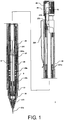
- FIG. 1 is a sectional view illustrating a mechanical pencil 1 according to this embodiment from the side, taken on a plane that includes the central axis thereof. The rear portion of the mechanical pencil 1 is illustrated from the side.
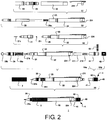
- FIG. 2 is an assembly process diagram illustrating an assembly process of the mechanical pencil 1 according to this embodiment from the side.
- the mechanical pencil 1 includes a front barrel 21, a packing (a writing lead holder) 211, a front tip pipe 21b, a rear barrel 22, an inner barrel 23, a fitting tube 24, a writing lead chucking/feeding out mechanism 25, a cushion spring 25a, a front piece 26, a screw portion pressing spring 26a, an eraser receptacle 271, an eraser 272, an outer barrel 3, and a clicking unit 4.
- a packing a writing lead holder
- a front tip pipe 21b As shown in FIGs. 1 and 2 , the mechanical pencil 1 includes a front barrel 21, a packing (a writing lead holder) 211, a front tip pipe 21b, a rear barrel 22, an inner barrel 23, a fitting tube 24, a writing lead chucking/feeding out mechanism 25, a cushion spring 25a, a front piece 26, a screw portion pressing spring 26a, an eraser receptacle 271, an eraser 272, an outer barrel 3, and a clicking unit 4.
- a packing a writing lead holder
- the rear barrel 22, the inner barrel 23, and the fitting tube 24 are all substantially tubular members, and these members, together with the front barrel 21 and the outer barrel 3, to be described in detail below, constitute a barrel assembly of the mechanical pencil 1.
- the fitting tube 24 is connected to the rear barrel 22 to be capable of rotating relative thereto by press-fitting a rear end portion of the fitting tube 24 into the rear barrel 22 from a front end side thereof.
- the fitting tube 24 is connected to the inner barrel 23 to be capable of rotating integrally therewith by press-fitting a front end portion of the fitting tube 24 into the inner barrel 23 from a rear end side thereof.
- the rear barrel 22 and the inner barrel 23 can rotate relative to each other.
- An attachment portion of a clip 224 is fitted onto an outer peripheral surface of a rear end portion of the rear barrel 22, whereby the clip 224 is attached to the rear barrel 22.
- a pair of cams 241 disposed at 180° intervals in a circumferential direction are formed on an inner peripheral surface of the fitting tube 24 so as to project radially inward from the inner peripheral surface.
- Each of the cams 241 has a cam front end shaped to project toward the front end side, and the cam front end contacts a cam surface formed on a sleeve 251, to be described in detail below, so as to follow the cam surface. Adjustment of a cushioning stroke realized by the cam 241 and the cam surface formed on the sleeve 251 will be described in detail below.
- the writing lead chucking/feeding out mechanism 25 is capable of chucking a writing lead 9 formed from thin, elongated graphite to enable writing, and capable of feeding the writing lead 9 forward in response to a clicking operation executed by a user. As illustrated in S2, the writing lead chucking/feeding out mechanism 25 is inserted into a rear barrel assembly constituted by the rear barrel 22, the inner barrel 23, and the fitting tube 24 from a front end side thereof in a condition where the cushion spring 25a, which is formed from a compression coil spring, is mounted on a rear portion outer periphery thereof.
- the cushion spring 25a is compressed in the axial direction between the rear barrel 22 and the writing lead chucking/feeding out mechanism 25 so as to bias the writing lead chucking/feeding out mechanism 25 frontward by a predetermined load.
- a cushioning mechanism of the mechanical pencil 1 having the cushion spring 25a is a mechanism for alleviating excessive writing pressure exerted on the writing lead 9 during writing by biasing the writing lead chucking/feeding out mechanism 25 frontward so as to be capable of retreating.
- the magnitude by which the writing pressure is alleviated can be adjusted by making a distance (the cushioning stroke) by which the writing lead chucking/feeding out mechanism 25 can retreat adjustable from zero (no alleviation) to a predetermined amount.
- the front barrel 21 is formed in a substantially tubular shape having a tapered front end side, and the packing 211, which has a central aperture for clamping the fed writing lead 9 by a predetermined pressure, is incorporated into a front end thereof.
- a front tip pipe 21b for guiding the writing lead 9 is press-fitted fixedly into the front end of the front barrel 21 so as to project by a predetermined amount.
- a screw portion 210b is formed on a rear end portion outer periphery of the front barrel 21, and in a condition where the front barrel 21 covers a front end portion of the writing lead chucking/feeding out mechanism 25, the screw portion 210b of the front barrel 21 is screwed to a corresponding screw portion formed on a front end portion inner periphery of the inner barrel 23.
- the front piece 26 is formed in a substantially tubular shape having a tapered front end side, and as illustrated in FIG. 10 , a screw portion 260b is formed on a rear end portion inner periphery thereof.
- the screw portion pressing spring 26a which is constituted by a compression coil spring, is mounted on the outer periphery of the front barrel 21, the screw portion 260b of the front piece 26 is screwed to a screw portion 211a (see FIG.
- the front tip pipe 21b press-fitted fixedly into the front end portion of the front barrel 21 is capable of projecting from and retracting into an opening formed in the front end of the front piece 26.
- the user can adjust the length by which the front tip pipe 21b projects from the front end of the front piece 26 by adjusting a set position of the front piece 26 relative to the front barrel 21.
- An elastomer O-ring 26b formed in an annular shape is attached to an outer periphery of the front piece 26.
- the O-ring 26b is attached between the front piece 26 and the outer barrel 3, and configured to press the front piece 26 inward in a radial direction.
- the O-ring 26b may be formed from any arbitrary material that is sufficiently elastic to be capable of pressing the front piece 26 in the radial direction.
- the eraser receptacle 271 is formed in a substantially tubular shape, and as illustrated in S4a, the eraser 272 is inserted into a rear portion thereof, while a front portion thereof is inserted into a rear end portion of the rear barrel 22 and attached to a rear end of the writing lead chucking/feeding out mechanism 25.
- An outer diameter of the rear portion of the eraser receptacle 271 is formed to be smaller than an inner diameter of the rear portion of the rear barrel 22 so that a gap for incorporating a click bar 41 is formed between an inner peripheral surface of the rear barrel 22 and an outer peripheral surface of the eraser receptacle 271.
- the clicking unit 4 includes the click bar 41, which is formed in a substantially tubular shape, a hardness indicator 42 for indicating a hardness of the writing lead 9, as selected by the user, and an indicator ring 43 that has an opening in one location on a side face thereof, through which the user can see a selected part of the hardness indicator 42, and is formed in a substantially tubular shape having a closed rear end surface to be fitted to a rear end portion of the click bar 41.
- the user can selectively expose to the outside a selected hardness indicator of the writing lead 9, which is written on the hardness indicator 42 adhered to the rear portion of the click bar 41, so that the exposed hardness indicator is displayed.
- the outer barrel 3 is a member formed in a substantially tubular shape and mounted on the respective outer peripheries of the front piece 26 and the inner barrel 23.
- An outer peripheral surface of the outer barrel 3 is knurled so that the user can grip the barrel more easily.
- a screw portion is formed on a rear end portion inner peripheral surface of the outer barrel 3, and in a condition where the outer barrel 3 covers the front barrel 21, the rear portion of the front piece 26, and the outer periphery of the inner barrel 23, the screw portion on the rear end portion inner peripheral surface of the outer barrel 3 is screwed to a screw portion formed on the rear portion outer peripheral surface of the inner barrel 23.
- the outer barrel 3 and the rear barrel 22 screwed integrally to the inner barrel 23 are capable of rotating relative to each other in order to facilitate an operation for adjusting the cushioning stroke, to be described in detail below.
- the click bar 41 of the clicking unit 4 is attached detachably to a rear portion outer peripheral surface of the eraser receptacle 271 protruding from the rear end of the rear barrel 22. When the clicking unit 4 is detached, the eraser 272 mounted in the eraser receptacle 271 can be used.
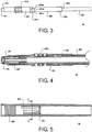
- FIG. 3 is a view illustrating the writing lead chucking/feeding out mechanism from the side.
- FIG. 4 is an enlarged sectional view illustrating an enlargement of the writing lead chucking/feeding out mechanism illustrated in FIG. 3 , taken on a plane that includes a central axis thereof.
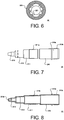
- FIG. 5 is a sectional view illustrating the rear barrel, taken on a plane that includes a central axis thereof.
- FIG. 6 is a sectional view illustrating the rear barrel according to this embodiment from the front, taken on an orthogonal plane to the central axis thereof.
- the writing lead chucking/feeding out mechanism 25 includes a central portion 250 formed in a tubular shape, a sleeve 251 formed integrally with the central portion 250 but having a larger outer diameter than the central portion 250, a writing lead pipe 252 mounted in the interior of the central portion 250 in order to house the writing lead 9, a chuck 253 capable of chucking the writing lead 9 and feeding the writing lead 9 forward, a chuck ring 254 mounted on the chuck 253, and a chuck spring 255 constituted by a compression coil spring and housed in the sleeve 251.
- the chuck spring 255 biases the writing lead pipe 252, into which a rear end portion of the chuck 253 is press-fitted, rearward against the sleeve 251.
- a front end portion of the chuck 253 is fitted to the chuck ring 254 such that the chuck ring 254 is sandwiched between the front end portion of the chuck 253 and a front end surface of the sleeve 251, whereby the chuck 253 is pressed radially inward by the front end portion of the chuck ring 254 fitted thereto so as to chuck the writing lead 9.
- the writing lead chucking/feeding out mechanism 25 is fed forward while chucking the writing lead 9.
- the chuck ring 254 contacts the barrel such that the chuck 253 moves forward relative to the chuck ring 254 against the biasing force of the chuck spring 255, whereby the fit between the chuck 253 and the chuck ring 254 is released, and as a result, the chuck on the writing lead 9 is released.
- the writing lead 9 remains clamped by the packing (the writing lead holder) 211 so as to be held in the fed position, and the chuck 253 and chuck ring 254 are caused to retreat by the biasing force of the chuck spring 255 while leaving the writing lead 9 fed forward.
- the chuck 253 and the chuck ring 254 chuck the writing lead 9 in a position further rearward than before.
- the sleeve 251 includes meshing portions 251a constituting the cushioning mechanism with which the cushioning stroke of the mechanical pencil 1 according to this embodiment can be adjusted, and an incorporation error absorption portion 251b for eliminating an axial direction incorporation error relative to a barrel of the central portion 250 and the sleeve 251. Cushioning stroke adjustment by the cushioning mechanism of the mechanical pencil 1 according to this embodiment will now be described.
- the pair of meshing portions 251a are formed on a rear end surface of the sleeve 251 at 180° intervals in the circumferential direction.
- the pair of meshing portions 251 a of the sleeve 251 are formed to respectively oppose the pair of cams 241 (see FIG. 1 ) formed on the inner peripheral surface of the fitting tube 24.
- Each of the meshing portions 251 a constitutes the cam surface opposing the cam 241, and includes a first part 251a1 serving as a rear cam surface, a second part 251a2 serving as a front cam surface, and a third part 251a3 serving as an intermediate cam surface positioned between the first part 251a1 and the second part 251a2 so as to connect the first part 251a1 and the second part 251a2.
- An engagement portion 250a that projects radially outward and is engaged to the inner peripheral surface of the rear barrel 22 is formed on a rear end of the central portion 250 of the writing lead chucking/feeding out mechanism 25, and as will be described in detail below, when the writing lead chucking/feeding out mechanism 25 is incorporated into the rear barrel 22, the rear barrel 22 and the writing lead chucking/feeding out mechanism 25 rotate integrally.
- the writing lead chucking/feeding out mechanism 25 is configured such that when the rear barrel 22 is rotated relative to the inner barrel 23 and the fitting tube 24, the writing lead chucking/feeding out mechanism 25 is capable of rotating together with the rear barrel 22 relative to the inner barrel 23 and the fitting tube 24 having the cams 241 formed on the inner peripheral surface thereof.
- the circumferential direction position in which the front end of the cam 241 contacts the meshing portion 251 a can be modified, and accordingly, the axial direction position of the front end of the cam 241 relative to the meshing portion 251a can be modified.
- the cushioning stroke i.e. an operating stroke of the cushion spring 25a that performs a cushioning operation while compressed in the axial direction between a latch portion 250b provided on a rear end of the central portion 250 and the rear barrel 22, can be modified.
- the cushioning stroke when the front end of the cam 241 contacts the first part 251a1 of the meshing portion 251a, the cushioning stroke is zero. In this case, the cushion spring 25a does not undergo compression deformation.
- the cushioning stroke reaches a maximum such that the cushion spring 25a is capable of compression deformation by the permitted cushioning stroke.
- the front end of the cam 241 contacts the third part 251 a3 of the meshing portion 251a, a cushioning stroke is performed at an intermediate cushioning stroke between zero and the maximum.
- the user can adjust the cushioning stroke as desired.
- the rear barrel 22 includes a latch portion 221 that is formed to project radially inward around the entire periphery of an inner peripheral surface thereof in order to latch a rear end portion of the cushion spring 25a.
- a connecting portion 222 constituted by a plurality of annular grooves extending in the circumferential direction is formed on the inner peripheral surface of the front portion of the rear barrel 22 in order to engage the fitting tube 24 so that the fitting tube 24 can rotate relative thereto.
- an engaged portion 223 constituted by a plurality of grooves that extend in the axial direction and are engaged to the engagement portion 250a of the writing lead chucking/feeding out mechanism 25 so that the writing lead chucking/feeding out mechanism 25 and the rear barrel 22 rotate integrally is formed on the inner peripheral surface of the rear barrel 22.
- the user can adjust the position in which the front end of the cam 241 contacts the meshing portion 251a by rotating the outer barrel 3 screwed to the inner barrel 23 relative to the rear barrel 22, and in so doing, the user can adjust the distance (the cushioning stroke) by which the writing lead chucking/feeding out mechanism 25 is capable of retreating. Therefore, the user of the mechanical pencil 1 can adjust a maximum load (a cushioning operation load) of the writing pressure exerted on the writing lead 9 in accordance with the hardness of the writing lead 9, the material of a paper surface, and so on.
- FIG. 7 is a view illustrating the front barrel 21 according to this embodiment from the side.
- FIG. 8 is a sectional view illustrating the front barrel 21 of FIG. 7 , taken on a plane that includes a central axis thereof.
- FIG. 9 is a view illustrating the front piece 26 according to this embodiment from the side.
- FIG. 10 is a sectional view illustrating the front piece 26 of FIG. 9 , taken on a plane that includes a central axis thereof.
- the front barrel 21 is formed in a substantially tubular shape having a plurality of parts with different outer diameters.
- the plurality of parts of the front barrel 21 can be broadly divided into a first diameter portion 210, a second diameter portion 211, a third diameter portion 212, and a fourth diameter portion 213, in order from the rear end side.
- the first diameter portion 210 is formed to have the largest outer diameter of the front barrel 21, and an outer peripheral surface thereof includes a flange 210a that projects radially outward around the entire periphery in order to latch a rear end portion of the screw portion pressing spring 26a.
- the screw portion 210b for screwing the outer peripheral surface of the front barrel 21 to the inner peripheral surface of the inner barrel 23 is formed on the outer peripheral surface of the first diameter portion 210 to the rear of the flange 210a.
- the second diameter portion 211 is formed to have a smaller outer diameter than the first diameter portion 210, and the screw portion 211a for screwing the outer peripheral surface of the front barrel 21 to the inner peripheral surface of the front piece 26 is formed on an outer peripheral surface thereof.
- the third diameter portion 212 is formed to have an outer diameter dimension "A", to be described in detail below, which is smaller than the outer diameter of the second diameter portion 211.
- the fourth diameter portion 213 is formed to have the smallest outer diameter of the front barrel 21 and a tapered front end, and a aperture 213a into which the front tip pipe 21b can be press-fitted is formed in a front end thereof.
- the front piece 26 includes, in order from the rear end side thereof, a trunk portion 260 formed in a substantially tubular shape, and a conical portion 261 formed in a substantially conical tubular shape.
- the conical portion 261 has a through hole in a front end thereof, through which the front tip pipe 21b of the front barrel 21 projects and retracts.
- the screw portion 260b is formed on an inner peripheral surface of the trunk portion 260, and screwed to the screw portion 211a on the outer peripheral surface of the second diameter portion 211 of the front barrel 21.
- an interior space 260a is formed in the front piece 26 so that when the front piece 26 is set maximally rearward relative to the front barrel 21, the inner peripheral surface of the front piece 26 approaches or contacts the outer peripheral surface of the front barrel 21 in the axial direction and the radial direction.
- An inner diameter "a" of the interior space 260a formed in the front piece 26 frontward of the trunk portion 260 is set in accordance with the outer diameter "A" (see FIG. 7 ) of the third diameter portion 212 of the front barrel 21 so that contact is substantially established therebetween.
- a knurled gripping portion 260c for facilitating an operation performed by the user to rotate the front piece 26 in the circumferential direction is formed on an outer peripheral surface of the trunk portion 260 of the front piece 26 so as to extend around the entire periphery thereof.
- a mounting groove 260d for mounting the O-ring 26b (see FIGs. 1 and 2 ) is formed in the outer peripheral surface of the rear end portion of the front piece 26 so as to extend around the entire periphery thereof. Front and rear walls of the mounting groove 260d are formed as inclined surfaces inclined such that a groove width increases radially outward. According to this configuration, a pressing force exerted by the O-ring 26b mounted on the front piece 26 to press the front piece 26 radially inward can be dispersed to the front and rear walls of the mounting groove 260d, and equilibrium can be achieved in the dispersed pressing force.
- the O-ring 26b can be brought into contact with the outer peripheral surface of the front piece 26 such that a plurality of contact portions are formed, and the pressing force exerted by each of the plurality of contact portions can be made uniform.
- a highly reliable contact condition can be obtained, and excessive stress on the O-ring 26b can be avoided so that the O-ring 26b can be used for a longer time.
- the front barrel 21, the front piece 26, the screw portion pressing spring 26a, and the O-ring 26b together constitute an adjustment mechanism capable of adjusting the amount by which the front tip pipe 21b of the front barrel 21 projects from the front end of the front piece 26.
- the user can operate the front piece 26 screwed to the front barrel 21 by gripping the gripping portion 260c of the front piece 26 and rotating the gripping portion 260c relative to the front barrel 21 about the central axis. By performing this adjustment operation, the relative axial direction set position of the front piece 26 relative to the front barrel 21 can be adjusted while maintaining the screw fastening between the front barrel 21 and the front piece 26.
- the front tip pipe 21b fixed to the front end of the front barrel 21 can be adjusted so as to project from the front end of the front piece 26 by an amount desired by the user, or so as to be housed completely inside the front piece 26.
- the adjusted position of the front piece 26, adjusted by the user is maintained by the O-ring 26b, which contacts and presses the front piece 26 around the entire periphery thereof from the radial direction outer side.
- a holding force by which the O-ring 26b holds the front piece 26 in the predetermined adjustment position does not differ according to differences in the adjusted position of the front piece 26.
- the respective screw portions of the front barrel 21 and the front piece 26 are biased by the screw portion pressing spring 26a such that the front barrel 21 and the front piece 26 are separated from each other in the axial direction.
- the screw portion pressing spring 26a By pressing the screw portions of the front barrel 21 and the front piece 26 in the axial direction using the screw portion pressing spring 26a, a screw thread on the screw portion 211 a of the front barrel 21 and a screw thread on the screw portion 260b of the front piece 26 contact each other tightly such that a frictional force on a contact surface between the screw portions can be increased.
- the magnitude of the pressing force applied in the axial direction by the screw portion pressing spring 26a is set such that the user cannot sense differences in a rotation operation force applied to the front piece 26 corresponding to differences in the adjusted position of the front piece 26.
- the holding force for holding the front piece 26 in the adjusted position can be increased further.
- the screw portion pressing spring 26a may be configured to bias the front barrel 21 and the front piece 26 toward each other in the axial direction. Likewise in this case, the respective screw portions of the front barrel 21 and the front piece 26 can be pressed.
- the screw portion pressing spring 26a may bias the front barrel 21 and the front piece 26 in any manner as long as the screw thread on the screw portion 211 a of the front barrel 21 and the screw thread on the screw portion 260b of the front piece 26 contact each other tightly.
- the O-ring 26b which is formed from an elastomer material, is attached to the front piece 26 so as to project to the radial direction outer side of the front piece 26 and configured to press the front piece 26 in the radial direction
- frictional force can be generated in the circumferential direction against the rotation of the front piece 26 while the O-ring 26b contacts the inner peripheral surface of the outer barrel 3 due to the O-ring 26b having a comparatively high frictional coefficient in comparison with other materials.
- the front tip pipe 21b can be held in the adjusted position with even greater stability.
- the configurations may be applied similarly to another adjustment mechanism for adjusting the axial direction set position of a movable member of another writing implement, such as an amount by which a tip of a ball pen projects from a nose cone, for example.
- a pressing member which in the embodiment is exemplified by the O-ring 26b, may be any member that presses the movable member in the radial direction, and the pressing member may press the movable member either radially inward or radially outward.
Landscapes
- Mechanical Pencils And Projecting And Retracting Systems Therefor, And Multi-System Writing Instruments (AREA)
Applications Claiming Priority (2)
| Application Number | Priority Date | Filing Date | Title |
|---|---|---|---|
| JP2017031086 | 2017-02-22 | ||
| PCT/JP2018/006158 WO2018155476A1 (fr) | 2017-02-22 | 2018-02-21 | Instrument pour écrire |
Publications (2)
| Publication Number | Publication Date |
|---|---|
| EP3587139A1 true EP3587139A1 (fr) | 2020-01-01 |
| EP3587139A4 EP3587139A4 (fr) | 2020-11-25 |
Family
ID=63254418
Family Applications (1)
| Application Number | Title | Priority Date | Filing Date |
|---|---|---|---|
| EP18757170.8A Withdrawn EP3587139A4 (fr) | 2017-02-22 | 2018-02-21 | Instrument pour écrire |
Country Status (7)
| Country | Link |
|---|---|
| US (1) | US20200009899A1 (fr) |
| EP (1) | EP3587139A4 (fr) |
| JP (1) | JP6840831B2 (fr) |
| KR (1) | KR20190113780A (fr) |
| CN (1) | CN110290931A (fr) |
| TW (1) | TW201831340A (fr) |
| WO (1) | WO2018155476A1 (fr) |
Families Citing this family (3)
| Publication number | Priority date | Publication date | Assignee | Title |
|---|---|---|---|---|
| JP7491927B2 (ja) | 2019-07-25 | 2024-05-28 | 株式会社パイロットコーポレーション | 出没式筆記具 |
| EP4146205A4 (fr) | 2020-05-05 | 2024-05-29 | Nuvalent, Inc. | Agents chimiothérapeutiques à base d'éther macrocyclique hétéroaromatique |
| JP7415228B2 (ja) * | 2020-06-29 | 2024-01-17 | ぺんてる株式会社 | シャープペンシル |
Family Cites Families (13)
| Publication number | Priority date | Publication date | Assignee | Title |
|---|---|---|---|---|
| JPS54179248U (fr) * | 1978-06-08 | 1979-12-18 | ||
| JPS59126687U (ja) * | 1983-02-15 | 1984-08-25 | オ−ト株式会社 | シヤ−プペンシル |
| JPS59157877U (ja) * | 1983-04-07 | 1984-10-23 | 堂元 芳治 | クツシヨン付きシヤ−プペンシル |
| US5018891A (en) * | 1989-07-10 | 1991-05-28 | Kotobuko & Co., Ltd. | Writing instrument with eraser dispenser |
| JP2505735Y2 (ja) * | 1990-05-18 | 1996-07-31 | 株式会社壽 | 回転式シャ―プペンシル |
| JP3141170B2 (ja) * | 1991-12-16 | 2001-03-05 | 株式会社壽 | シャープペンシルのクッション機構 |
| JP3877629B2 (ja) * | 2002-04-04 | 2007-02-07 | 末峰 高橋 | 改良型ノック式シャープペンシル |
| JP4448659B2 (ja) | 2003-01-22 | 2010-04-14 | 高橋 末峰 | 改良型ノック式シャープペンシル |
| US7806615B1 (en) * | 2007-10-26 | 2010-10-05 | Mitsubishi Pencil Co., Ltd. | Mechanical pencil |
| US7850380B2 (en) * | 2007-10-26 | 2010-12-14 | Mitsubishi Pencil Co., Ltd. | Mechanical pencil |
| JP2012076399A (ja) * | 2010-10-05 | 2012-04-19 | Pilot Corporation | 出没式シャープペンシル |
| JP5711047B2 (ja) * | 2011-05-30 | 2015-04-30 | ゼブラ株式会社 | シャープペンシル |
| JP6293539B2 (ja) * | 2014-03-20 | 2018-03-14 | 株式会社壽 | シャープペンシル |
-
2017
- 2017-11-02 TW TW106137989A patent/TW201831340A/zh unknown
-
2018
- 2018-02-21 WO PCT/JP2018/006158 patent/WO2018155476A1/fr not_active Ceased
- 2018-02-21 EP EP18757170.8A patent/EP3587139A4/fr not_active Withdrawn
- 2018-02-21 KR KR1020197021198A patent/KR20190113780A/ko not_active Withdrawn
- 2018-02-21 US US16/482,678 patent/US20200009899A1/en not_active Abandoned
- 2018-02-21 CN CN201880011442.2A patent/CN110290931A/zh not_active Withdrawn
- 2018-02-21 JP JP2019501366A patent/JP6840831B2/ja active Active
Also Published As
| Publication number | Publication date |
|---|---|
| JP6840831B2 (ja) | 2021-03-10 |
| TW201831340A (zh) | 2018-09-01 |
| US20200009899A1 (en) | 2020-01-09 |
| JPWO2018155476A1 (ja) | 2019-12-19 |
| EP3587139A4 (fr) | 2020-11-25 |
| CN110290931A (zh) | 2019-09-27 |
| KR20190113780A (ko) | 2019-10-08 |
| WO2018155476A1 (fr) | 2018-08-30 |
Similar Documents
| Publication | Publication Date | Title |
|---|---|---|
| EP3587139A1 (fr) | Instrument pour écrire | |
| US10500891B2 (en) | Mechanical pencil | |
| WO2019168194A1 (fr) | Crayon mécanique | |
| US20190344603A1 (en) | Mechanical pencil | |
| US20200062022A1 (en) | Writing instrument holder and writing instrument holder set | |
| US20210162797A1 (en) | Writing instrument and method for manufacturing writing instrument | |
| US20150202692A1 (en) | Chuck | |
| CN110087892A (zh) | 自动铅笔 | |
| KR20180114929A (ko) | 공구용 척 및 공구 유지 방법 및 공구 분리 방법 | |
| JP6645916B2 (ja) | シャープペンシル | |
| US5827000A (en) | Writing instrument | |
| JP2023070970A (ja) | 筆記具 | |
| US20190375230A1 (en) | Mechanical pencil | |
| JP2012106452A (ja) | シャープペンシル | |
| US20190344602A1 (en) | Barrel assembly, writing instrument, and container | |
| JP2017013289A (ja) | シャープペンシル | |
| JPH077198Y2 (ja) | 芯出可変機構付きシャープペンシル | |
| JP2002192881A (ja) | シャープペンシル | |
| JP6976844B2 (ja) | 筆記具 | |
| JP7261032B2 (ja) | シャープペンシルユニット及び出没式筆記具 | |
| JP3188602U (ja) | シャープペンシル | |
| WO2014092123A1 (fr) | Corps de mandrin et crayon mécanique | |
| JP5525427B2 (ja) | シャープペンシル | |
| JPH0546488U (ja) | シャープペンシルのノック釦固定構造 | |
| JP2020110928A (ja) | シャープペンシルユニット及び出没式筆記具 |
Legal Events
| Date | Code | Title | Description |
|---|---|---|---|
| PUAI | Public reference made under article 153(3) epc to a published international application that has entered the european phase |
Free format text: ORIGINAL CODE: 0009012 |
|
| 17P | Request for examination filed |
Effective date: 20190919 |
|
| AK | Designated contracting states |
Kind code of ref document: A1 Designated state(s): AL AT BE BG CH CY CZ DE DK EE ES FI FR GB GR HR HU IE IS IT LI LT LU LV MC MK MT NL NO PL PT RO RS SE SI SK SM TR |
|
| AX | Request for extension of the european patent |
Extension state: BA ME |
|
| DAV | Request for validation of the european patent (deleted) | ||
| DAX | Request for extension of the european patent (deleted) | ||
| STAA | Information on the status of an ep patent application or granted ep patent |
Free format text: STATUS: THE APPLICATION HAS BEEN WITHDRAWN |
|
| A4 | Supplementary search report drawn up and despatched |
Effective date: 20201028 |
|
| RIC1 | Information provided on ipc code assigned before grant |
Ipc: B43K 24/02 20060101ALI20201022BHEP Ipc: B43K 21/00 20060101AFI20201022BHEP Ipc: B43K 21/16 20060101ALI20201022BHEP |
|
| 18W | Application withdrawn |
Effective date: 20201116 |