EP3587736A1 - Surface portante composite présentant une fissure dans la plateforme - Google Patents
Surface portante composite présentant une fissure dans la plateforme Download PDFInfo
- Publication number
- EP3587736A1 EP3587736A1 EP19180976.3A EP19180976A EP3587736A1 EP 3587736 A1 EP3587736 A1 EP 3587736A1 EP 19180976 A EP19180976 A EP 19180976A EP 3587736 A1 EP3587736 A1 EP 3587736A1
- Authority
- EP
- European Patent Office
- Prior art keywords
- fiber layers
- airfoil
- platform
- cleft
- section
- Prior art date
- Legal status (The legal status is an assumption and is not a legal conclusion. Google has not performed a legal analysis and makes no representation as to the accuracy of the status listed.)
- Granted
Links
Images

Classifications
-
- F—MECHANICAL ENGINEERING; LIGHTING; HEATING; WEAPONS; BLASTING
- F01—MACHINES OR ENGINES IN GENERAL; ENGINE PLANTS IN GENERAL; STEAM ENGINES
- F01D—NON-POSITIVE DISPLACEMENT MACHINES OR ENGINES, e.g. STEAM TURBINES
- F01D5/00—Blades; Blade-carrying members; Heating, heat-insulating, cooling or antivibration means on the blades or the members
- F01D5/12—Blades
- F01D5/28—Selecting particular materials; Particular measures relating thereto; Measures against erosion or corrosion
- F01D5/282—Selecting composite materials, e.g. blades with reinforcing filaments
-
- B—PERFORMING OPERATIONS; TRANSPORTING
- B29—WORKING OF PLASTICS; WORKING OF SUBSTANCES IN A PLASTIC STATE IN GENERAL
- B29C—SHAPING OR JOINING OF PLASTICS; SHAPING OF MATERIAL IN A PLASTIC STATE, NOT OTHERWISE PROVIDED FOR; AFTER-TREATMENT OF THE SHAPED PRODUCTS, e.g. REPAIRING
- B29C70/00—Shaping composites, i.e. plastics material comprising reinforcements, fillers or preformed parts, e.g. inserts
- B29C70/04—Shaping composites, i.e. plastics material comprising reinforcements, fillers or preformed parts, e.g. inserts comprising reinforcements only, e.g. self-reinforcing plastics
- B29C70/28—Shaping operations therefor
- B29C70/30—Shaping by lay-up, i.e. applying fibres, tape or broadsheet on a mould, former or core; Shaping by spray-up, i.e. spraying of fibres on a mould, former or core
- B29C70/34—Shaping by lay-up, i.e. applying fibres, tape or broadsheet on a mould, former or core; Shaping by spray-up, i.e. spraying of fibres on a mould, former or core and shaping or impregnating by compression, i.e. combined with compressing after the lay-up operation
-
- F—MECHANICAL ENGINEERING; LIGHTING; HEATING; WEAPONS; BLASTING
- F01—MACHINES OR ENGINES IN GENERAL; ENGINE PLANTS IN GENERAL; STEAM ENGINES
- F01D—NON-POSITIVE DISPLACEMENT MACHINES OR ENGINES, e.g. STEAM TURBINES
- F01D9/00—Stators
- F01D9/02—Nozzles; Nozzle boxes; Stator blades; Guide conduits, e.g. individual nozzles
- F01D9/04—Nozzles; Nozzle boxes; Stator blades; Guide conduits, e.g. individual nozzles forming ring or sector
- F01D9/041—Nozzles; Nozzle boxes; Stator blades; Guide conduits, e.g. individual nozzles forming ring or sector using blades
-
- B—PERFORMING OPERATIONS; TRANSPORTING
- B29—WORKING OF PLASTICS; WORKING OF SUBSTANCES IN A PLASTIC STATE IN GENERAL
- B29L—INDEXING SCHEME ASSOCIATED WITH SUBCLASS B29C, RELATING TO PARTICULAR ARTICLES
- B29L2031/00—Other particular articles
- B29L2031/748—Machines or parts thereof not otherwise provided for
- B29L2031/7504—Turbines
-
- F—MECHANICAL ENGINEERING; LIGHTING; HEATING; WEAPONS; BLASTING
- F05—INDEXING SCHEMES RELATING TO ENGINES OR PUMPS IN VARIOUS SUBCLASSES OF CLASSES F01-F04
- F05D—INDEXING SCHEME FOR ASPECTS RELATING TO NON-POSITIVE-DISPLACEMENT MACHINES OR ENGINES, GAS-TURBINES OR JET-PROPULSION PLANTS
- F05D2230/00—Manufacture
- F05D2230/50—Building or constructing in particular ways
-
- F—MECHANICAL ENGINEERING; LIGHTING; HEATING; WEAPONS; BLASTING
- F05—INDEXING SCHEMES RELATING TO ENGINES OR PUMPS IN VARIOUS SUBCLASSES OF CLASSES F01-F04
- F05D—INDEXING SCHEME FOR ASPECTS RELATING TO NON-POSITIVE-DISPLACEMENT MACHINES OR ENGINES, GAS-TURBINES OR JET-PROPULSION PLANTS
- F05D2240/00—Components
- F05D2240/10—Stators
- F05D2240/12—Fluid guiding means, e.g. vanes
-
- F—MECHANICAL ENGINEERING; LIGHTING; HEATING; WEAPONS; BLASTING
- F05—INDEXING SCHEMES RELATING TO ENGINES OR PUMPS IN VARIOUS SUBCLASSES OF CLASSES F01-F04
- F05D—INDEXING SCHEME FOR ASPECTS RELATING TO NON-POSITIVE-DISPLACEMENT MACHINES OR ENGINES, GAS-TURBINES OR JET-PROPULSION PLANTS
- F05D2240/00—Components
- F05D2240/20—Rotors
- F05D2240/30—Characteristics of rotor blades, i.e. of any element transforming dynamic fluid energy to or from rotational energy and being attached to a rotor
-
- F—MECHANICAL ENGINEERING; LIGHTING; HEATING; WEAPONS; BLASTING
- F05—INDEXING SCHEMES RELATING TO ENGINES OR PUMPS IN VARIOUS SUBCLASSES OF CLASSES F01-F04
- F05D—INDEXING SCHEME FOR ASPECTS RELATING TO NON-POSITIVE-DISPLACEMENT MACHINES OR ENGINES, GAS-TURBINES OR JET-PROPULSION PLANTS
- F05D2240/00—Components
- F05D2240/80—Platforms for stationary or moving blades
-
- F—MECHANICAL ENGINEERING; LIGHTING; HEATING; WEAPONS; BLASTING
- F05—INDEXING SCHEMES RELATING TO ENGINES OR PUMPS IN VARIOUS SUBCLASSES OF CLASSES F01-F04
- F05D—INDEXING SCHEME FOR ASPECTS RELATING TO NON-POSITIVE-DISPLACEMENT MACHINES OR ENGINES, GAS-TURBINES OR JET-PROPULSION PLANTS
- F05D2250/00—Geometry
- F05D2250/70—Shape
- F05D2250/75—Shape given by its similarity to a letter, e.g. T-shaped
-
- F—MECHANICAL ENGINEERING; LIGHTING; HEATING; WEAPONS; BLASTING
- F05—INDEXING SCHEMES RELATING TO ENGINES OR PUMPS IN VARIOUS SUBCLASSES OF CLASSES F01-F04
- F05D—INDEXING SCHEME FOR ASPECTS RELATING TO NON-POSITIVE-DISPLACEMENT MACHINES OR ENGINES, GAS-TURBINES OR JET-PROPULSION PLANTS
- F05D2300/00—Materials; Properties thereof
- F05D2300/60—Properties or characteristics given to material by treatment or manufacturing
- F05D2300/603—Composites; e.g. fibre-reinforced
-
- F—MECHANICAL ENGINEERING; LIGHTING; HEATING; WEAPONS; BLASTING
- F05—INDEXING SCHEMES RELATING TO ENGINES OR PUMPS IN VARIOUS SUBCLASSES OF CLASSES F01-F04
- F05D—INDEXING SCHEME FOR ASPECTS RELATING TO NON-POSITIVE-DISPLACEMENT MACHINES OR ENGINES, GAS-TURBINES OR JET-PROPULSION PLANTS
- F05D2300/00—Materials; Properties thereof
- F05D2300/60—Properties or characteristics given to material by treatment or manufacturing
- F05D2300/603—Composites; e.g. fibre-reinforced
- F05D2300/6034—Orientation of fibres, weaving, ply angle
-
- Y—GENERAL TAGGING OF NEW TECHNOLOGICAL DEVELOPMENTS; GENERAL TAGGING OF CROSS-SECTIONAL TECHNOLOGIES SPANNING OVER SEVERAL SECTIONS OF THE IPC; TECHNICAL SUBJECTS COVERED BY FORMER USPC CROSS-REFERENCE ART COLLECTIONS [XRACs] AND DIGESTS
- Y02—TECHNOLOGIES OR APPLICATIONS FOR MITIGATION OR ADAPTATION AGAINST CLIMATE CHANGE
- Y02T—CLIMATE CHANGE MITIGATION TECHNOLOGIES RELATED TO TRANSPORTATION
- Y02T50/00—Aeronautics or air transport
- Y02T50/60—Efficient propulsion technologies, e.g. for aircraft
Definitions
- a gas turbine engine typically includes a fan section, a compressor section, a combustor section and a turbine section. Air entering the compressor section is compressed and delivered into the combustion section where it is mixed with fuel and ignited to generate a high-speed exhaust gas flow. The high-speed exhaust gas flow expands through the turbine section to drive the compressor and the fan section.
- the compressor section typically includes low and high pressure compressors, and the turbine section includes low and high pressure turbines.
- the high pressure turbine drives the high pressure compressor through an outer shaft to form a high spool
- the low pressure turbine drives the low pressure compressor through an inner shaft to form a low spool.
- the fan section may also be driven by the low inner shaft.
- a direct drive gas turbine engine includes a fan section driven by the low spool such that the low pressure compressor, low pressure turbine and fan section rotate at a common speed in a common direction.
- An airfoil component includes a platform that has a gaspath side and a non-gaspath side, and an airfoil that is joined through a transition section to the platform.
- the platform and airfoil are formed of a composite material that have fiber layers.
- the fiber layers are contiguous in the airfoil and diverging in the transition section such that a first portion of the fiber layers forms a first section of the platform on a first side of the airfoil and a second portion of the fiber layers forms a second section of the platform on a second side of the airfoil.
- the diverging of the fiber layers establishes an open elongated cleft along the non-gaspath side of the platform.
- the composite material is a polymer matrix composite.
- the cleft is V-shaped.
- a further embodiment of any of the foregoing embodiments includes cover fiber layers extending through the cleft, the airfoil excluding the cover fiber layers.
- the fiber layers at the cleft are consolidated.
- the composite material is a fully cured polymer matrix composite.
- a method for fabricating an airfoil component includes placing fiber layers into a mold to form a platform that has a gaspath side and a non-gaspath side and an airfoil that is joined through a transition section to the platform.
- the fiber layers are contiguous in the airfoil and diverge in the transition section such that a first portion of the fiber layers extends on a first side of the airfoil and a second portion of the fiber layers extends on a second side of the airfoil.
- the diverging of the fiber layers establish an open elongated cleft along the non-gaspath side of the platform.
- the fiber layers are consolidated by inserting a ridge of a mold tool to into the cleft and then exerting pressure on the fiber layers using the mold tool.
- the consolidating includes heating the fiber layers.
- the cleft and ridge are V-shaped.
- a further embodiment of any of the foregoing embodiments includes placing cover fiber layers to extend through the cleft, the airfoil excluding the cover fiber layers.
- the fiber layers are preimpregnated fiber layers.
- a composite component according to an example of the present disclosure includes a T-shaped intersection that has a flange that has a first side and a second side, and a leg that is joined through a transition section to the flange.
- the flange and the leg are formed of a composite material that have fiber layers.
- the fiber layers are contiguous in the leg and diverge in the transition section such that a first portion of the fiber layers forms a first section of the flange on a first side of the leg and a second portion of the fiber layers forms a second section of the flange on a second side of the leg.
- the diverging of the fiber layers establishes an open elongated cleft along the second side of the flange.
- the composite material is a polymer matrix composite.
- the cleft is V-shaped.
- a further embodiment of any of the foregoing embodiments includes cover fiber layers extending through the cleft, the leg excluding the cover fiber layers.
- the fiber layers at the cleft are consolidated.
- the composite material is a fully cured polymer matrix composite.
- the leg is an airfoil and the flange is a platform.
- FIG. 1 schematically illustrates a gas turbine engine 20.
- the gas turbine engine 20 is disclosed herein as a two-spool turbofan that generally incorporates a fan section 22, a compressor section 24, a combustor section 26 and a turbine section 28.
- the fan section 22 drives air along a bypass flow path B in a bypass duct defined within a nacelle 15, and also drives air along a core flow path C for compression and communication into the combustor section 26 then expansion through the turbine section 28.
- FIG. 1 schematically illustrates a gas turbine engine 20.
- the gas turbine engine 20 is disclosed herein as a two-spool turbofan that generally incorporates a fan section 22, a compressor section 24, a combustor section 26 and a turbine section 28.
- the fan section 22 drives air along a bypass flow path B in a bypass duct defined within a nacelle 15, and also drives air along a core flow path C for compression and communication into the combustor section 26 then expansion through the turbine section 28.
- FIG. 1 schematic
- the exemplary engine 20 generally includes a low speed spool 30 and a high speed spool 32 mounted for rotation about an engine central longitudinal axis A relative to an engine static structure 36 via several bearing systems 38. It should be understood that various bearing systems 38 at various locations may alternatively or additionally be provided, and the location of bearing systems 38 may be varied as appropriate to the application.
- the low speed spool 30 generally includes an inner shaft 40 that interconnects, a first (or low) pressure compressor 44 and a first (or low) pressure turbine 46.
- the inner shaft 40 is connected to the fan 42 through a speed change mechanism, which in exemplary gas turbine engine 20 is illustrated as a geared architecture 48 to drive a fan 42 at a lower speed than the low speed spool 30.
- the high speed spool 32 includes an outer shaft 50 that interconnects a second (or high) pressure compressor 52 and a second (or high) pressure turbine 54.
- a combustor 56 is arranged in exemplary gas turbine 20 between the high pressure compressor 52 and the high pressure turbine 54.
- a mid-turbine frame 57 of the engine static structure 36 may be arranged generally between the high pressure turbine 54 and the low pressure turbine 46.
- the mid-turbine frame 57 further supports bearing systems 38 in the turbine section 28.
- the inner shaft 40 and the outer shaft 50 are concentric and rotate via bearing systems 38 about the engine central longitudinal axis A which is colline
- the core airflow is compressed by the low pressure compressor 44 then the high pressure compressor 52, mixed and burned with fuel in the combustor 56, then expanded over the high pressure turbine 54 and low pressure turbine 46.
- the mid-turbine frame 57 includes airfoils 59 which are in the core airflow path C.
- the turbines 46, 54 rotationally drive the respective low speed spool 30 and high speed spool 32 in response to the expansion.
- gear system 48 may be located aft of the low pressure compressor, or aft of the combustor section 26 or even aft of turbine section 28, and fan 42 may be positioned forward or aft of the location of gear system 48.
- the engine 20 in one example is a high-bypass geared aircraft engine.
- the engine 20 bypass ratio is greater than about six (6), with an example embodiment being greater than about ten (10)
- the geared architecture 48 is an epicyclic gear train, such as a planetary gear system or other gear system, with a gear reduction ratio of greater than about 2.3 and the low pressure turbine 46 has a pressure ratio that is greater than about five.
- the engine 20 bypass ratio is greater than about ten (10:1)
- the fan diameter is significantly larger than that of the low pressure compressor 44
- the low pressure turbine 46 has a pressure ratio that is greater than about five (5:1).
- Low pressure turbine 46 pressure ratio is pressure measured prior to inlet of low pressure turbine 46 as related to the pressure at the outlet of the low pressure turbine 46 prior to an exhaust nozzle.
- the geared architecture 48 may be an epicycle gear train, such as a planetary gear system or other gear system, with a gear reduction ratio of greater than about 2.3:1 and less than about 5:1. It should be understood, however, that the above parameters are only exemplary of one embodiment of a geared architecture engine and that the present invention is applicable to other gas turbine engines including direct drive turbofans.
- the fan section 22 of the engine 20 is designed for a particular flight condition -- typically cruise at about 0.8 Mach and about 35,000 feet (10,668 meters).
- the flight condition of 0.8 Mach and 35,000 ft (10,668 meters), with the engine at its best fuel consumption - also known as "bucket cruise Thrust Specific Fuel Consumption ('TSFC')" - is the industry standard parameter of lbm of fuel being burned divided by lbf of thrust the engine produces at that minimum point.
- "Low fan pressure ratio” is the pressure ratio across the fan blade alone, without a Fan Exit Guide Vane (“FEGV”) system.
- the low fan pressure ratio as disclosed herein according to one non-limiting embodiment is less than about 1.45.
- Low corrected fan tip speed is the actual fan tip speed in ft/sec divided by an industry standard temperature correction of [(Tram °R) / (518.7 °R)] 0.5 .
- the "Low corrected fan tip speed” as disclosed herein according to one non-limiting embodiment is less than about 1150 ft / second (350.5 meters/second).
- the engine 20 includes a row of airfoil components (composite components), which in this example are static vanes 60 ("vanes 60") in the compressor section 24.
- composite components which in this example are static vanes 60 ("vanes 60") in the compressor section 24.
- vanes 60 static vanes 60
- the examples herein will be described with respect to the vanes 60, it is to be understood that the examples can extend to other types of airfoils, such as rotatable blades, other vane multiplets, vane singlets, and to other types of non-airfoil composite structures.
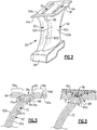
- FIG. 2 illustrates an example of several of the vanes 60.
- the vanes 60 are provided as vane doublet segments. Such segments are arranged circumferentially to form a full row of vanes 60.
- the vane doublet segment includes two airfoils 62 that share a common outer diameter platform 64 and an inner diameter box structure 66.
- Each airfoil 62 includes a leading and trailing ends 62a/62b, and first and second sides 62c/62d (typically pressure and suction sides).
- the platform 64 includes a first or gaspath side 64a and a second or non-gaspath side 64b.
- gaspath and non-gaspath are made with reference to the main bypass airflow.
- the gaspath side 64a bounds the main bypass airflow in the bypass flow path B of the engine 20.
- each airfoil 62 is joined through a transition section 68 to the platform 64 to form a T-shaped intersection.
- the airfoil 62 would be a leg and the platform 64 would be a flange.
- the airfoil 62 and the platform 64 are formed of a composite material 70 having fiber layers 72.
- Figure 4 shows a representative example of the fiber layers 72.
- the fiber layers 72 include fibers 72a that are embedded in a matrix 72b between the fibers 72a.
- the fibers in a fiber layer 72 may be single filaments but more typically will be bundles of filaments in the form of tows or yarns. As an example, a single tow may have several thousand filaments.
- the tows or yarns of a fiber layer 72 may be arranged in a fiber architecture, which here refers to an ordered arrangement of the tows or yarns relative to one another in a fiber layer 72.
- the type of ordered arrangement may include, but is not limited to, unidirectional, 2- or 3-dimensional woven, triaxial braid, and non-crimp fabric. There may also be variations within a type of arrangement, such as the relative angles of the tows to one another.
- the composite material 70 is a polymer matrix composite.
- the matrix 72b is polymer-based.
- Example polymers may include, but are not limited to, epoxy, polyimide, and bismaleimide.
- Example fibers 72a may include, but are not limited to, carbon fibers, glass fibers, and aramid fibers. In one example, all of the fiber layers 72 of the vanes 60 are identical with regard to the type of fibers 72a and type of polymer matrix 72b.
- some of the fiber layers 72 may be one type of fibers 72a (e.g., one of glass, carbon, or aramid) and polymer matrix 72b (e.g., one of epoxy, polyimide, or bismaleimide) and other of the fiber layers 72 may be a different type of fibers 72a (e.g., a different one of glass, carbon, or aramid) and polymer matrix 72b (e.g., a different one of epoxy, polyimide, or bismaleimide).
- fibers 72a e.g., one of glass, carbon, or aramid
- polymer matrix 72b e.g., a different one of epoxy, polyimide, or bismaleimide
- the fiber layers 72 are contiguous in the airfoil 62. Each fiber layer 72 is directly next to and in contact with the next fiber layer 72 in a stacked arrangement. The fiber layers 72 then diverge in the transition section 68.
- the transition section 68 is the region where the fiber layers 72 bend to transition from the airfoil 62 to the platform 64.
- a first portion (designated at 74a) of the fiber layers 72 diverges to form a first section 76a of the platform 64 on the first side 62a of the airfoil 62 and a second portion (designated at 74b) of the fiber layers 72 diverges to form a second section 76b of the platform 64 on the second side 62b of the airfoil 62.
- the diverging of the fiber layers 72 establishes an open elongated cleft 78 (see also Figure 2 ) along the non-gaspath side 64b of the platform 64. That is, the diverging of the fiber layers 72 defines the cleft 78 and, but for the diverging, the cleft 78 would not exist.
- the cleft 78 is V-shaped.
- the V-shape is not a perfect "V" but rather has a rounded nose and legs or sides of equal or unequal length.
- the fiber layers 72 at the cleft 78 are consolidated.
- the fiber layers 72 in the transition section 68 were formed by application of heat and pressure to remove or substantially remove voids, distribute the polymer of the matrix 72b, and fully cure the polymer matrix 72b.
- cover fiber layers 80 that extend through the cleft 78.
- the layers 80 could be excluded.
- the layers 80 do not fill the cleft 78 but have the effect of smoothing over the nose of the V-shape and reinforcing the platform 64.
- the layers 80 extend only in the platform 64, although the layers 80 may extend into a portion of the transition section 68.
- the airfoil 62 excludes the layers 80.
- the layers 80 are also fully consolidated.
- the cleft 78 serves to strengthen the vane 60 but is also a vestige of the process of fabricating the vane 60.
- Figure 5 depicts an example process or method of fabricating the vane 60.
- the vane 60 can be fabricated in a molding process that includes placing the fiber layers 72 into a mold tool 82 that has a ridge 82a. Initially, the fiber layers 72 are in an uncured or partially cured state, such as pre-impregnated fiber layers. The fiber layers 72 can be placed into the mold tool 82 by hand or by an automated or partially automated process. Once in place, the mold tool 82, only part of which is shown, closes.
- the ridge 82a is inserted into the cleft 78. This can be achieved by placing the fiber layers 72 in the transition section 68 over the ridge 82a, by moving the ridge 82a into the cleft 78 during closing of the mold tool 82, or a combination of placement and closing of the mold tool 82.
- the ridge 82a has a profile that matches the profile of the cleft 78. Thus, the ridge 82a, once inserted, bears against the surfaces of the cleft 78.
- the mold tool 82 applies heat and pressure to the fiber layers 72, as denoted by the arrows in the figure.
- the heart and pressure forms the fiber layers 72 to the final or near final shape of the vane 60 and consolidates the fiber layers 72.
- the fiber layers 72 are consolidated by the ridge 82a of the mold tool 82, in which the fiber layers 72 in the area of the transition section 68 are compressed between the ridge 82a and another part of the mold tool 82 that bears against the airfoil 62.
- the heat and pressure remove or substantially remove voids, distribute the polymer of the matrix 72b, and fully cure the polymer.
- the ridge 82a since the profile of the ridge 82a matches the profile of the cleft 78 and bears against the surfaces of the cleft 78, the ridge 82a evenly applies the pressure and heat in the transition section 68, which may enhance the strength of the vane 60 in the transition section 68.
- pressure cannot be applied fully or evenly because it may inadvertently shift the noodle or filler and/or wrinkle the fiber layers.
- the region near the noodle or filler cannot be properly consolidated and may be weaker than most other portions of the structure that are fully consolidated.
- the cleft 78 in cooperation with the ridge 82a, permits enhanced consolidation.
Landscapes
- Engineering & Computer Science (AREA)
- Chemical & Material Sciences (AREA)
- Materials Engineering (AREA)
- Mechanical Engineering (AREA)
- Composite Materials (AREA)
- General Engineering & Computer Science (AREA)
- Structures Of Non-Positive Displacement Pumps (AREA)
- Turbine Rotor Nozzle Sealing (AREA)
Applications Claiming Priority (1)
| Application Number | Priority Date | Filing Date | Title |
|---|---|---|---|
| US16/015,318 US20190390555A1 (en) | 2018-06-22 | 2018-06-22 | Composite airfoil with cleft in platform |
Publications (3)
| Publication Number | Publication Date |
|---|---|
| EP3587736A1 true EP3587736A1 (fr) | 2020-01-01 |
| EP3587736B1 EP3587736B1 (fr) | 2021-02-17 |
| EP3587736B8 EP3587736B8 (fr) | 2021-04-07 |
Family
ID=66998196
Family Applications (1)
| Application Number | Title | Priority Date | Filing Date |
|---|---|---|---|
| EP19180976.3A Active EP3587736B8 (fr) | 2018-06-22 | 2019-06-18 | Aube de turbine composite avec des fibre se partager dans la plateforme |
Country Status (2)
| Country | Link |
|---|---|
| US (1) | US20190390555A1 (fr) |
| EP (1) | EP3587736B8 (fr) |
Cited By (2)
| Publication number | Priority date | Publication date | Assignee | Title |
|---|---|---|---|---|
| EP4030037A1 (fr) * | 2021-01-15 | 2022-07-20 | Raytheon Technologies Corporation | Profil aérodynamique à structure fourchue en fibre composite |
| US11920495B1 (en) | 2023-01-20 | 2024-03-05 | Rtx Corporation | Airfoil with thick wishbone fiber structure |
Families Citing this family (5)
| Publication number | Priority date | Publication date | Assignee | Title |
|---|---|---|---|---|
| US11346228B1 (en) * | 2021-02-23 | 2022-05-31 | Raytheon Technologies Corporation | Airfoil with flange formed of wishbone-shaped fiber layer structure |
| US11781435B2 (en) * | 2022-02-28 | 2023-10-10 | Rtx Corporation | Bifurcated fabric architecture for airfoils, methods of manufacture thereof and airfoils comprising the same |
| US11732589B1 (en) * | 2022-07-15 | 2023-08-22 | Raytheon Technologies Corporation | Airfoil vane multiplet with interleaved fiber plies |
| US11965430B1 (en) | 2023-09-11 | 2024-04-23 | Rtx Corporation | Flared mandrel and process for effective use in transition regions |
| US12467385B1 (en) | 2025-01-09 | 2025-11-11 | General Electric Company | Outlet guide vane mount |
Citations (6)
| Publication number | Priority date | Publication date | Assignee | Title |
|---|---|---|---|---|
| US5639535A (en) * | 1996-06-06 | 1997-06-17 | The Boeing Company | Composite interleaving for composite interfaces |
| EP2363574A2 (fr) * | 2010-02-24 | 2011-09-07 | United Technologies Corporation | Fabrication d'aube rotative utilisant un composite de matrice en céramique |
| EP2562360A2 (fr) * | 2011-08-23 | 2013-02-27 | United Technologies Corporation | Structure d'aube composite à matrice céramique comportant un enveloppement pour moteur de turbine à gaz |
| US20150231849A1 (en) * | 2014-02-18 | 2015-08-20 | The Boeing Company | Composite Filler |
| EP3002117A1 (fr) * | 2014-09-30 | 2016-04-06 | The Boeing Company | Structure composite ayant des têtes de clou à surface réduite et procédé de fabricaton de celle-ci |
| EP3004560A1 (fr) * | 2013-06-04 | 2016-04-13 | United Technologies Corporation | Ensemble pale comprenant des agencements de fibres continues à deux et trois dimensions |
Family Cites Families (9)
| Publication number | Priority date | Publication date | Assignee | Title |
|---|---|---|---|---|
| JP4060981B2 (ja) * | 1998-04-08 | 2008-03-12 | 本田技研工業株式会社 | ガスタービンの静翼構造体及びそのユニット |
| US6821087B2 (en) * | 2002-01-21 | 2004-11-23 | Honda Giken Kogyo Kabushiki Kaisha | Flow-rectifying member and its unit and method for producing flow-rectifying member |
| GB2447271B (en) * | 2007-03-06 | 2010-02-17 | Rolls Royce Plc | A composite structure |
| US20130004715A1 (en) * | 2011-06-29 | 2013-01-03 | United Technologies Corporation | Reinforced composite t-joint |
| BR112014016859B1 (pt) * | 2012-01-09 | 2021-02-09 | Snecma | processo de realização de uma preforma fibrosa para a fabricação de uma pá de turbomáquina, preforma fibrosa de uma pá de turbomáquina, pá de ventoinha de turbomáquina e ventoinha de turbomáquina |
| US9517594B2 (en) * | 2012-10-04 | 2016-12-13 | The Boeing Company | Composite structure having a stabilizing element |
| JP6526528B2 (ja) * | 2015-09-11 | 2019-06-05 | 株式会社東芝 | 半導体装置 |
| US10046525B2 (en) * | 2016-09-30 | 2018-08-14 | The Boeing Company | Advanced variable radius laminated composite radius filler |
| US10577939B2 (en) * | 2016-11-01 | 2020-03-03 | Rolls-Royce Corporation | Turbine blade with three-dimensional CMC construction elements |
-
2018
- 2018-06-22 US US16/015,318 patent/US20190390555A1/en not_active Abandoned
-
2019
- 2019-06-18 EP EP19180976.3A patent/EP3587736B8/fr active Active
Patent Citations (6)
| Publication number | Priority date | Publication date | Assignee | Title |
|---|---|---|---|---|
| US5639535A (en) * | 1996-06-06 | 1997-06-17 | The Boeing Company | Composite interleaving for composite interfaces |
| EP2363574A2 (fr) * | 2010-02-24 | 2011-09-07 | United Technologies Corporation | Fabrication d'aube rotative utilisant un composite de matrice en céramique |
| EP2562360A2 (fr) * | 2011-08-23 | 2013-02-27 | United Technologies Corporation | Structure d'aube composite à matrice céramique comportant un enveloppement pour moteur de turbine à gaz |
| EP3004560A1 (fr) * | 2013-06-04 | 2016-04-13 | United Technologies Corporation | Ensemble pale comprenant des agencements de fibres continues à deux et trois dimensions |
| US20150231849A1 (en) * | 2014-02-18 | 2015-08-20 | The Boeing Company | Composite Filler |
| EP3002117A1 (fr) * | 2014-09-30 | 2016-04-06 | The Boeing Company | Structure composite ayant des têtes de clou à surface réduite et procédé de fabricaton de celle-ci |
Cited By (3)
| Publication number | Priority date | Publication date | Assignee | Title |
|---|---|---|---|---|
| EP4030037A1 (fr) * | 2021-01-15 | 2022-07-20 | Raytheon Technologies Corporation | Profil aérodynamique à structure fourchue en fibre composite |
| US11725522B2 (en) | 2021-01-15 | 2023-08-15 | Raytheon Technologies Corporation | Airfoil with wishbone fiber structure |
| US11920495B1 (en) | 2023-01-20 | 2024-03-05 | Rtx Corporation | Airfoil with thick wishbone fiber structure |
Also Published As
| Publication number | Publication date |
|---|---|
| EP3587736B1 (fr) | 2021-02-17 |
| US20190390555A1 (en) | 2019-12-26 |
| EP3587736B8 (fr) | 2021-04-07 |
Similar Documents
| Publication | Publication Date | Title |
|---|---|---|
| EP3587736B1 (fr) | Aube de turbine composite avec des fibre se partager dans la plateforme | |
| US11346363B2 (en) | Composite airfoil for gas turbine | |
| US11105215B2 (en) | Feather seal slot arrangement for a CMC BOAS assembly | |
| US10443617B2 (en) | Functionally graded composite fan containment case | |
| US10006301B2 (en) | Vane assembly including two- and three-dimensional arrangements of continuous fibers | |
| US9957821B2 (en) | Gas turbine engine composite airfoil trailing edge | |
| US11519291B2 (en) | Integral stiffening rail for braided composite gas turbine engine component | |
| US20160341071A1 (en) | Compressed chopped fiber composite fan blade platform | |
| US10287918B2 (en) | Composite attachment structure with 3D weave | |
| US11156126B2 (en) | Fan case with interleaved layers | |
| US10428684B2 (en) | Turbine airfoil with additive manufactured reinforcement of thermoplastic body | |
| US20170030205A1 (en) | Fan blade platform spacer mounting | |
| US20150315922A1 (en) | Gas turbine engine with reinforced spinner | |
| US11242991B2 (en) | CMC component arrangement and method of manufacture | |
| US20250116193A1 (en) | CMC Airfoil with Cooling Passage Having Multi-Dimensional Plenum | |
| US12078083B2 (en) | Contour weaves for interwoven vanes | |
| US11732589B1 (en) | Airfoil vane multiplet with interleaved fiber plies |
Legal Events
| Date | Code | Title | Description |
|---|---|---|---|
| PUAI | Public reference made under article 153(3) epc to a published international application that has entered the european phase |
Free format text: ORIGINAL CODE: 0009012 |
|
| STAA | Information on the status of an ep patent application or granted ep patent |
Free format text: STATUS: THE APPLICATION HAS BEEN PUBLISHED |
|
| AK | Designated contracting states |
Kind code of ref document: A1 Designated state(s): AL AT BE BG CH CY CZ DE DK EE ES FI FR GB GR HR HU IE IS IT LI LT LU LV MC MK MT NL NO PL PT RO RS SE SI SK SM TR |
|
| AX | Request for extension of the european patent |
Extension state: BA ME |
|
| STAA | Information on the status of an ep patent application or granted ep patent |
Free format text: STATUS: REQUEST FOR EXAMINATION WAS MADE |
|
| 17P | Request for examination filed |
Effective date: 20200625 |
|
| RBV | Designated contracting states (corrected) |
Designated state(s): AL AT BE BG CH CY CZ DE DK EE ES FI FR GB GR HR HU IE IS IT LI LT LU LV MC MK MT NL NO PL PT RO RS SE SI SK SM TR |
|
| GRAP | Despatch of communication of intention to grant a patent |
Free format text: ORIGINAL CODE: EPIDOSNIGR1 |
|
| STAA | Information on the status of an ep patent application or granted ep patent |
Free format text: STATUS: GRANT OF PATENT IS INTENDED |
|
| INTG | Intention to grant announced |
Effective date: 20200918 |
|
| GRAS | Grant fee paid |
Free format text: ORIGINAL CODE: EPIDOSNIGR3 |
|
| GRAA | (expected) grant |
Free format text: ORIGINAL CODE: 0009210 |
|
| STAA | Information on the status of an ep patent application or granted ep patent |
Free format text: STATUS: THE PATENT HAS BEEN GRANTED |
|
| AK | Designated contracting states |
Kind code of ref document: B1 Designated state(s): AL AT BE BG CH CY CZ DE DK EE ES FI FR GB GR HR HU IE IS IT LI LT LU LV MC MK MT NL NO PL PT RO RS SE SI SK SM TR |
|
| REG | Reference to a national code |
Ref country code: GB Ref legal event code: FG4D |
|
| REG | Reference to a national code |
Ref country code: CH Ref legal event code: EP |
|
| REG | Reference to a national code |
Ref country code: DE Ref legal event code: R096 Ref document number: 602019002551 Country of ref document: DE |
|
| REG | Reference to a national code |
Ref country code: DE Ref legal event code: R081 Ref document number: 602019002551 Country of ref document: DE Owner name: RAYTHEON TECHNOLOGIES CORPORATION, FARMINGTON, US Free format text: FORMER OWNER: UNITED TECHNOLOGIES CORP., FARMINGTON, CONN., US Ref country code: DE Ref legal event code: R081 Ref document number: 602019002551 Country of ref document: DE Owner name: RTX CORPORATION (N.D.GES.D. STAATES DELAWARE),, US Free format text: FORMER OWNER: UNITED TECHNOLOGIES CORP., FARMINGTON, CONN., US |
|
| REG | Reference to a national code |
Ref country code: CH Ref legal event code: PK Free format text: BERICHTIGUNG B8 Ref country code: AT Ref legal event code: REF Ref document number: 1361731 Country of ref document: AT Kind code of ref document: T Effective date: 20210315 |
|
| REG | Reference to a national code |
Ref country code: IE Ref legal event code: FG4D |
|
| RAP2 | Party data changed (patent owner data changed or rights of a patent transferred) |
Owner name: RAYTHEON TECHNOLOGIES CORPORATION |
|
| REG | Reference to a national code |
Ref country code: LT Ref legal event code: MG9D |
|
| REG | Reference to a national code |
Ref country code: NL Ref legal event code: MP Effective date: 20210217 |
|
| PG25 | Lapsed in a contracting state [announced via postgrant information from national office to epo] |
Ref country code: FI Free format text: LAPSE BECAUSE OF FAILURE TO SUBMIT A TRANSLATION OF THE DESCRIPTION OR TO PAY THE FEE WITHIN THE PRESCRIBED TIME-LIMIT Effective date: 20210217 Ref country code: GR Free format text: LAPSE BECAUSE OF FAILURE TO SUBMIT A TRANSLATION OF THE DESCRIPTION OR TO PAY THE FEE WITHIN THE PRESCRIBED TIME-LIMIT Effective date: 20210518 Ref country code: BG Free format text: LAPSE BECAUSE OF FAILURE TO SUBMIT A TRANSLATION OF THE DESCRIPTION OR TO PAY THE FEE WITHIN THE PRESCRIBED TIME-LIMIT Effective date: 20210517 Ref country code: HR Free format text: LAPSE BECAUSE OF FAILURE TO SUBMIT A TRANSLATION OF THE DESCRIPTION OR TO PAY THE FEE WITHIN THE PRESCRIBED TIME-LIMIT Effective date: 20210217 Ref country code: NO Free format text: LAPSE BECAUSE OF FAILURE TO SUBMIT A TRANSLATION OF THE DESCRIPTION OR TO PAY THE FEE WITHIN THE PRESCRIBED TIME-LIMIT Effective date: 20210517 Ref country code: PT Free format text: LAPSE BECAUSE OF FAILURE TO SUBMIT A TRANSLATION OF THE DESCRIPTION OR TO PAY THE FEE WITHIN THE PRESCRIBED TIME-LIMIT Effective date: 20210617 Ref country code: LT Free format text: LAPSE BECAUSE OF FAILURE TO SUBMIT A TRANSLATION OF THE DESCRIPTION OR TO PAY THE FEE WITHIN THE PRESCRIBED TIME-LIMIT Effective date: 20210217 |
|
| REG | Reference to a national code |
Ref country code: AT Ref legal event code: MK05 Ref document number: 1361731 Country of ref document: AT Kind code of ref document: T Effective date: 20210217 |
|
| PG25 | Lapsed in a contracting state [announced via postgrant information from national office to epo] |
Ref country code: SE Free format text: LAPSE BECAUSE OF FAILURE TO SUBMIT A TRANSLATION OF THE DESCRIPTION OR TO PAY THE FEE WITHIN THE PRESCRIBED TIME-LIMIT Effective date: 20210217 Ref country code: RS Free format text: LAPSE BECAUSE OF FAILURE TO SUBMIT A TRANSLATION OF THE DESCRIPTION OR TO PAY THE FEE WITHIN THE PRESCRIBED TIME-LIMIT Effective date: 20210217 Ref country code: LV Free format text: LAPSE BECAUSE OF FAILURE TO SUBMIT A TRANSLATION OF THE DESCRIPTION OR TO PAY THE FEE WITHIN THE PRESCRIBED TIME-LIMIT Effective date: 20210217 Ref country code: NL Free format text: LAPSE BECAUSE OF FAILURE TO SUBMIT A TRANSLATION OF THE DESCRIPTION OR TO PAY THE FEE WITHIN THE PRESCRIBED TIME-LIMIT Effective date: 20210217 Ref country code: PL Free format text: LAPSE BECAUSE OF FAILURE TO SUBMIT A TRANSLATION OF THE DESCRIPTION OR TO PAY THE FEE WITHIN THE PRESCRIBED TIME-LIMIT Effective date: 20210217 |
|
| PG25 | Lapsed in a contracting state [announced via postgrant information from national office to epo] |
Ref country code: IS Free format text: LAPSE BECAUSE OF FAILURE TO SUBMIT A TRANSLATION OF THE DESCRIPTION OR TO PAY THE FEE WITHIN THE PRESCRIBED TIME-LIMIT Effective date: 20210617 |
|
| PG25 | Lapsed in a contracting state [announced via postgrant information from national office to epo] |
Ref country code: CZ Free format text: LAPSE BECAUSE OF FAILURE TO SUBMIT A TRANSLATION OF THE DESCRIPTION OR TO PAY THE FEE WITHIN THE PRESCRIBED TIME-LIMIT Effective date: 20210217 Ref country code: EE Free format text: LAPSE BECAUSE OF FAILURE TO SUBMIT A TRANSLATION OF THE DESCRIPTION OR TO PAY THE FEE WITHIN THE PRESCRIBED TIME-LIMIT Effective date: 20210217 Ref country code: SM Free format text: LAPSE BECAUSE OF FAILURE TO SUBMIT A TRANSLATION OF THE DESCRIPTION OR TO PAY THE FEE WITHIN THE PRESCRIBED TIME-LIMIT Effective date: 20210217 Ref country code: AT Free format text: LAPSE BECAUSE OF FAILURE TO SUBMIT A TRANSLATION OF THE DESCRIPTION OR TO PAY THE FEE WITHIN THE PRESCRIBED TIME-LIMIT Effective date: 20210217 |
|
| REG | Reference to a national code |
Ref country code: DE Ref legal event code: R097 Ref document number: 602019002551 Country of ref document: DE |
|
| PG25 | Lapsed in a contracting state [announced via postgrant information from national office to epo] |
Ref country code: SK Free format text: LAPSE BECAUSE OF FAILURE TO SUBMIT A TRANSLATION OF THE DESCRIPTION OR TO PAY THE FEE WITHIN THE PRESCRIBED TIME-LIMIT Effective date: 20210217 Ref country code: RO Free format text: LAPSE BECAUSE OF FAILURE TO SUBMIT A TRANSLATION OF THE DESCRIPTION OR TO PAY THE FEE WITHIN THE PRESCRIBED TIME-LIMIT Effective date: 20210217 Ref country code: DK Free format text: LAPSE BECAUSE OF FAILURE TO SUBMIT A TRANSLATION OF THE DESCRIPTION OR TO PAY THE FEE WITHIN THE PRESCRIBED TIME-LIMIT Effective date: 20210217 |
|
| PLBE | No opposition filed within time limit |
Free format text: ORIGINAL CODE: 0009261 |
|
| STAA | Information on the status of an ep patent application or granted ep patent |
Free format text: STATUS: NO OPPOSITION FILED WITHIN TIME LIMIT |
|
| 26N | No opposition filed |
Effective date: 20211118 |
|
| PG25 | Lapsed in a contracting state [announced via postgrant information from national office to epo] |
Ref country code: MC Free format text: LAPSE BECAUSE OF FAILURE TO SUBMIT A TRANSLATION OF THE DESCRIPTION OR TO PAY THE FEE WITHIN THE PRESCRIBED TIME-LIMIT Effective date: 20210217 Ref country code: AL Free format text: LAPSE BECAUSE OF FAILURE TO SUBMIT A TRANSLATION OF THE DESCRIPTION OR TO PAY THE FEE WITHIN THE PRESCRIBED TIME-LIMIT Effective date: 20210217 Ref country code: ES Free format text: LAPSE BECAUSE OF FAILURE TO SUBMIT A TRANSLATION OF THE DESCRIPTION OR TO PAY THE FEE WITHIN THE PRESCRIBED TIME-LIMIT Effective date: 20210217 |
|
| PG25 | Lapsed in a contracting state [announced via postgrant information from national office to epo] |
Ref country code: SI Free format text: LAPSE BECAUSE OF FAILURE TO SUBMIT A TRANSLATION OF THE DESCRIPTION OR TO PAY THE FEE WITHIN THE PRESCRIBED TIME-LIMIT Effective date: 20210217 |
|
| REG | Reference to a national code |
Ref country code: BE Ref legal event code: MM Effective date: 20210630 |
|
| PG25 | Lapsed in a contracting state [announced via postgrant information from national office to epo] |
Ref country code: LU Free format text: LAPSE BECAUSE OF NON-PAYMENT OF DUE FEES Effective date: 20210618 |
|
| PG25 | Lapsed in a contracting state [announced via postgrant information from national office to epo] |
Ref country code: IT Free format text: LAPSE BECAUSE OF FAILURE TO SUBMIT A TRANSLATION OF THE DESCRIPTION OR TO PAY THE FEE WITHIN THE PRESCRIBED TIME-LIMIT Effective date: 20210217 Ref country code: IE Free format text: LAPSE BECAUSE OF NON-PAYMENT OF DUE FEES Effective date: 20210618 |
|
| PG25 | Lapsed in a contracting state [announced via postgrant information from national office to epo] |
Ref country code: IS Free format text: LAPSE BECAUSE OF FAILURE TO SUBMIT A TRANSLATION OF THE DESCRIPTION OR TO PAY THE FEE WITHIN THE PRESCRIBED TIME-LIMIT Effective date: 20210617 |
|
| PG25 | Lapsed in a contracting state [announced via postgrant information from national office to epo] |
Ref country code: BE Free format text: LAPSE BECAUSE OF NON-PAYMENT OF DUE FEES Effective date: 20210630 |
|
| REG | Reference to a national code |
Ref country code: CH Ref legal event code: PL |
|
| PG25 | Lapsed in a contracting state [announced via postgrant information from national office to epo] |
Ref country code: LI Free format text: LAPSE BECAUSE OF NON-PAYMENT OF DUE FEES Effective date: 20220630 Ref country code: CH Free format text: LAPSE BECAUSE OF NON-PAYMENT OF DUE FEES Effective date: 20220630 |
|
| P01 | Opt-out of the competence of the unified patent court (upc) registered |
Effective date: 20230521 |
|
| PG25 | Lapsed in a contracting state [announced via postgrant information from national office to epo] |
Ref country code: CY Free format text: LAPSE BECAUSE OF FAILURE TO SUBMIT A TRANSLATION OF THE DESCRIPTION OR TO PAY THE FEE WITHIN THE PRESCRIBED TIME-LIMIT Effective date: 20210217 |
|
| PG25 | Lapsed in a contracting state [announced via postgrant information from national office to epo] |
Ref country code: HU Free format text: LAPSE BECAUSE OF FAILURE TO SUBMIT A TRANSLATION OF THE DESCRIPTION OR TO PAY THE FEE WITHIN THE PRESCRIBED TIME-LIMIT; INVALID AB INITIO Effective date: 20190618 |
|
| PG25 | Lapsed in a contracting state [announced via postgrant information from national office to epo] |
Ref country code: MK Free format text: LAPSE BECAUSE OF FAILURE TO SUBMIT A TRANSLATION OF THE DESCRIPTION OR TO PAY THE FEE WITHIN THE PRESCRIBED TIME-LIMIT Effective date: 20210217 |
|
| PG25 | Lapsed in a contracting state [announced via postgrant information from national office to epo] |
Ref country code: MT Free format text: LAPSE BECAUSE OF FAILURE TO SUBMIT A TRANSLATION OF THE DESCRIPTION OR TO PAY THE FEE WITHIN THE PRESCRIBED TIME-LIMIT Effective date: 20210217 |
|
| PGFP | Annual fee paid to national office [announced via postgrant information from national office to epo] |
Ref country code: DE Payment date: 20250520 Year of fee payment: 7 |
|
| PGFP | Annual fee paid to national office [announced via postgrant information from national office to epo] |
Ref country code: GB Payment date: 20250520 Year of fee payment: 7 |
|
| PGFP | Annual fee paid to national office [announced via postgrant information from national office to epo] |
Ref country code: FR Payment date: 20250520 Year of fee payment: 7 |
|
| REG | Reference to a national code |
Ref country code: DE Ref legal event code: R081 Ref document number: 602019002551 Country of ref document: DE Owner name: RTX CORPORATION (N.D.GES.D. STAATES DELAWARE),, US Free format text: FORMER OWNER: RAYTHEON TECHNOLOGIES CORPORATION, FARMINGTON, CT, US |
|
| PG25 | Lapsed in a contracting state [announced via postgrant information from national office to epo] |
Ref country code: TR Free format text: LAPSE BECAUSE OF FAILURE TO SUBMIT A TRANSLATION OF THE DESCRIPTION OR TO PAY THE FEE WITHIN THE PRESCRIBED TIME-LIMIT Effective date: 20210217 |