EP3588643B1 - Unité de réaction électrochimique, empilement de cellules de réaction électrochimique, et procédé de production pour unité de réaction électrochimique - Google Patents
Unité de réaction électrochimique, empilement de cellules de réaction électrochimique, et procédé de production pour unité de réaction électrochimique Download PDFInfo
- Publication number
- EP3588643B1 EP3588643B1 EP18757019.7A EP18757019A EP3588643B1 EP 3588643 B1 EP3588643 B1 EP 3588643B1 EP 18757019 A EP18757019 A EP 18757019A EP 3588643 B1 EP3588643 B1 EP 3588643B1
- Authority
- EP
- European Patent Office
- Prior art keywords
- electrochemical reaction
- felt
- cathode
- anode
- unit
- Prior art date
- Legal status (The legal status is an assumption and is not a legal conclusion. Google has not performed a legal analysis and makes no representation as to the accuracy of the status listed.)
- Active
Links
Images


Classifications
-
- C—CHEMISTRY; METALLURGY
- C25—ELECTROLYTIC OR ELECTROPHORETIC PROCESSES; APPARATUS THEREFOR
- C25B—ELECTROLYTIC OR ELECTROPHORETIC PROCESSES FOR THE PRODUCTION OF COMPOUNDS OR NON-METALS; APPARATUS THEREFOR
- C25B1/00—Electrolytic production of inorganic compounds or non-metals
- C25B1/01—Products
- C25B1/02—Hydrogen or oxygen
- C25B1/04—Hydrogen or oxygen by electrolysis of water
-
- C—CHEMISTRY; METALLURGY
- C25—ELECTROLYTIC OR ELECTROPHORETIC PROCESSES; APPARATUS THEREFOR
- C25B—ELECTROLYTIC OR ELECTROPHORETIC PROCESSES FOR THE PRODUCTION OF COMPOUNDS OR NON-METALS; APPARATUS THEREFOR
- C25B13/00—Diaphragms; Spacing elements
- C25B13/04—Diaphragms; Spacing elements characterised by the material
-
- C—CHEMISTRY; METALLURGY
- C25—ELECTROLYTIC OR ELECTROPHORETIC PROCESSES; APPARATUS THEREFOR
- C25B—ELECTROLYTIC OR ELECTROPHORETIC PROCESSES FOR THE PRODUCTION OF COMPOUNDS OR NON-METALS; APPARATUS THEREFOR
- C25B9/00—Cells or assemblies of cells; Constructional parts of cells; Assemblies of constructional parts, e.g. electrode-diaphragm assemblies; Process-related cell features
- C25B9/70—Assemblies comprising two or more cells
- C25B9/73—Assemblies comprising two or more cells of the filter-press type
- C25B9/77—Assemblies comprising two or more cells of the filter-press type having diaphragms
-
- H—ELECTRICITY
- H01—ELECTRIC ELEMENTS
- H01M—PROCESSES OR MEANS, e.g. BATTERIES, FOR THE DIRECT CONVERSION OF CHEMICAL ENERGY INTO ELECTRICAL ENERGY
- H01M8/00—Fuel cells; Manufacture thereof
- H01M8/02—Details
- H01M8/0271—Sealing or supporting means around electrodes, matrices or membranes
- H01M8/0273—Sealing or supporting means around electrodes, matrices or membranes with sealing or supporting means in the form of a frame
-
- H—ELECTRICITY
- H01—ELECTRIC ELEMENTS
- H01M—PROCESSES OR MEANS, e.g. BATTERIES, FOR THE DIRECT CONVERSION OF CHEMICAL ENERGY INTO ELECTRICAL ENERGY
- H01M8/00—Fuel cells; Manufacture thereof
- H01M8/02—Details
- H01M8/0271—Sealing or supporting means around electrodes, matrices or membranes
- H01M8/0276—Sealing means characterised by their form
-
- H—ELECTRICITY
- H01—ELECTRIC ELEMENTS
- H01M—PROCESSES OR MEANS, e.g. BATTERIES, FOR THE DIRECT CONVERSION OF CHEMICAL ENERGY INTO ELECTRICAL ENERGY
- H01M8/00—Fuel cells; Manufacture thereof
- H01M8/02—Details
- H01M8/0271—Sealing or supporting means around electrodes, matrices or membranes
- H01M8/028—Sealing means characterised by their material
- H01M8/0282—Inorganic material
-
- H—ELECTRICITY
- H01—ELECTRIC ELEMENTS
- H01M—PROCESSES OR MEANS, e.g. BATTERIES, FOR THE DIRECT CONVERSION OF CHEMICAL ENERGY INTO ELECTRICAL ENERGY
- H01M8/00—Fuel cells; Manufacture thereof
- H01M8/02—Details
- H01M8/0271—Sealing or supporting means around electrodes, matrices or membranes
- H01M8/0286—Processes for forming seals
-
- H—ELECTRICITY
- H01—ELECTRIC ELEMENTS
- H01M—PROCESSES OR MEANS, e.g. BATTERIES, FOR THE DIRECT CONVERSION OF CHEMICAL ENERGY INTO ELECTRICAL ENERGY
- H01M8/00—Fuel cells; Manufacture thereof
- H01M8/06—Combination of fuel cells with means for production of reactants or for treatment of residues
- H01M8/0662—Treatment of gaseous reactants or gaseous residues, e.g. cleaning
-
- H—ELECTRICITY
- H01—ELECTRIC ELEMENTS
- H01M—PROCESSES OR MEANS, e.g. BATTERIES, FOR THE DIRECT CONVERSION OF CHEMICAL ENERGY INTO ELECTRICAL ENERGY
- H01M8/00—Fuel cells; Manufacture thereof
- H01M8/10—Fuel cells with solid electrolytes
- H01M8/12—Fuel cells with solid electrolytes operating at high temperature, e.g. with stabilised ZrO2 electrolyte
-
- H—ELECTRICITY
- H01—ELECTRIC ELEMENTS
- H01M—PROCESSES OR MEANS, e.g. BATTERIES, FOR THE DIRECT CONVERSION OF CHEMICAL ENERGY INTO ELECTRICAL ENERGY
- H01M8/00—Fuel cells; Manufacture thereof
- H01M8/24—Grouping of fuel cells, e.g. stacking of fuel cells
- H01M8/241—Grouping of fuel cells, e.g. stacking of fuel cells with solid or matrix-supported electrolytes
- H01M8/242—Grouping of fuel cells, e.g. stacking of fuel cells with solid or matrix-supported electrolytes comprising framed electrodes or intermediary frame-like gaskets
-
- H—ELECTRICITY
- H01—ELECTRIC ELEMENTS
- H01M—PROCESSES OR MEANS, e.g. BATTERIES, FOR THE DIRECT CONVERSION OF CHEMICAL ENERGY INTO ELECTRICAL ENERGY
- H01M8/00—Fuel cells; Manufacture thereof
- H01M8/24—Grouping of fuel cells, e.g. stacking of fuel cells
- H01M8/241—Grouping of fuel cells, e.g. stacking of fuel cells with solid or matrix-supported electrolytes
- H01M8/2425—High-temperature cells with solid electrolytes
- H01M8/2432—Grouping of unit cells of planar configuration
-
- H—ELECTRICITY
- H01—ELECTRIC ELEMENTS
- H01M—PROCESSES OR MEANS, e.g. BATTERIES, FOR THE DIRECT CONVERSION OF CHEMICAL ENERGY INTO ELECTRICAL ENERGY
- H01M8/00—Fuel cells; Manufacture thereof
- H01M8/10—Fuel cells with solid electrolytes
- H01M8/12—Fuel cells with solid electrolytes operating at high temperature, e.g. with stabilised ZrO2 electrolyte
- H01M2008/1293—Fuel cells with solid oxide electrolytes
-
- Y—GENERAL TAGGING OF NEW TECHNOLOGICAL DEVELOPMENTS; GENERAL TAGGING OF CROSS-SECTIONAL TECHNOLOGIES SPANNING OVER SEVERAL SECTIONS OF THE IPC; TECHNICAL SUBJECTS COVERED BY FORMER USPC CROSS-REFERENCE ART COLLECTIONS [XRACs] AND DIGESTS
- Y02—TECHNOLOGIES OR APPLICATIONS FOR MITIGATION OR ADAPTATION AGAINST CLIMATE CHANGE
- Y02E—REDUCTION OF GREENHOUSE GAS [GHG] EMISSIONS, RELATED TO ENERGY GENERATION, TRANSMISSION OR DISTRIBUTION
- Y02E60/00—Enabling technologies; Technologies with a potential or indirect contribution to GHG emissions mitigation
- Y02E60/30—Hydrogen technology
- Y02E60/36—Hydrogen production from non-carbon containing sources, e.g. by water electrolysis
-
- Y—GENERAL TAGGING OF NEW TECHNOLOGICAL DEVELOPMENTS; GENERAL TAGGING OF CROSS-SECTIONAL TECHNOLOGIES SPANNING OVER SEVERAL SECTIONS OF THE IPC; TECHNICAL SUBJECTS COVERED BY FORMER USPC CROSS-REFERENCE ART COLLECTIONS [XRACs] AND DIGESTS
- Y02—TECHNOLOGIES OR APPLICATIONS FOR MITIGATION OR ADAPTATION AGAINST CLIMATE CHANGE
- Y02E—REDUCTION OF GREENHOUSE GAS [GHG] EMISSIONS, RELATED TO ENERGY GENERATION, TRANSMISSION OR DISTRIBUTION
- Y02E60/00—Enabling technologies; Technologies with a potential or indirect contribution to GHG emissions mitigation
- Y02E60/30—Hydrogen technology
- Y02E60/50—Fuel cells
Definitions
- the technique disclosed in the present specification relates to an electrochemical reaction unit.
- the electricity generation unit may include a felt member for, for example, filling a space surrounding the unit cell to thereby improve electricity generation performance.
- a felt member is required to have flexibility and thermal resistance.
- the felt member is formed of, for example, a metal-containing felt material (e.g., nickel felt) or a ceramic-containing felt material (e.g., alumina felt) (see, for example, Japanese Patent Application Laid-Open (kokai) No. H05-166529 ).
- JP 2011-169326 A discloses a holding and sealing material for catalytic converters.
- Such a ceramic-containing felt material or metal-containing felt material may contain a contaminant such as Si.
- a contaminant e.g., Si
- electrolysis cell unit which is a constitutive unit of a solid oxide electrolysis cell (hereinafter may be referred to as "SOEC") for generating hydrogen by utilizing the electrolysis of water.
- SOEC solid oxide electrolysis cell
- a fuel cell electricity generation unit and an electrolysis cell unit are collectively referred to as an “electrochemical reaction unit.”
- electrochemical reaction units other than SOFC and SOEC.
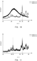
- the felt member since the felt member includes both a first crystal structure and a second crystal structure (i.e., an SiO 2 crystal structure), scattering of Si or another contaminant from the felt member can be reduced, to thereby prevent impairment of the performance of the unit cell, which would otherwise occur due to poisoning caused by Si or another contaminant.
- a first crystal structure i.e., an SiO 2 crystal structure
- the gas passage member 27 and the insulation sheets 26 disposed respectively on the upper end and on the lower end of the gas passage member 27 intervene between the nut 24 and the surface of the end plate 106.
- the insulation sheet 26 is formed of, for example, a mica sheet, a ceramic fiber sheet, a ceramic compact sheet, a glass sheet, or a glass ceramic composite material.
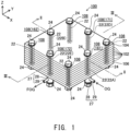
- a space defined by the bolt 22 (bolt 22A) located at around the midpoint of one side of the perimeter about the Z-axis direction of the fuel cell stack 100 (a side at the positive side in the X-axis direction of two sides in parallel with the Y-axis) and the communication hole 108 into which the bolt 22A is inserted functions as an oxidizer gas introduction manifold 161 into which oxidizer gas OG is introduced from outside the fuel cell stack 100 and which serves as a gas flow channel for supplying the oxidizer gas OG to the electricity generation units 102
- a space defined by the bolt 22 (bolt 22B) located at around the midpoint of the other side opposite the above side (a side at the negative side in the X-axis direction of two sides in parallel with the Y-axis) and the communication hole 108 into which the bolt 22B is inserted functions as an oxidizer gas discharge manifold 162 from which oxidizer offgas OOG discharged from the cathode chambers 166 of the electricity generation
- a space defined by the bolt 22 (bolt 22D) located at around the midpoint of one side of the perimeter about the Z-axis direction of the fuel cell stack 100 (a side at the positive side in the Y-axis direction of two sides in parallel with the X-axis) and the communication hole 108 into which the bolt 22D is inserted functions as a fuel gas introduction manifold 171 into which fuel gas FG is introduced from outside the fuel cell stack 100 and which supplies the fuel gas FG to the electricity generation units 102
- a space defined by the bolt 22 (bolt 22E) located at around the midpoint of the other side opposite the above side (a side at the negative side in the Y-axis direction of two sides in parallel with the X-axis) and the communication hole 108 into which the bolt 22E is inserted functions as a fuel gas discharge manifold 172 from which fuel offgas FOG discharged from the anode chambers 176 of the electricity generation units 102 is discharged to the outside of the fuel
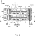
- the interconnector 150 is an electrically conductive member having an approximately rectangular flat plate shape and is formed of, for example, ferritic stainless steel.
- the interconnector 150 secures electrical conductivity between the electricity generation units 102 and prevents mixing of reaction gases between the electricity generation units 102.
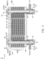
- two electricity generation units 102 are disposed adjacent to each other, and the two adjacent electricity generation units 102 share one interconnector 150. That is, the upper interconnector 150 of a certain electricity generation unit 102 serves as a lower interconnector 150 of the upper adjacent electricity generation unit 102.
- the electrolyte layer 112 is a member having an approximately rectangular (as viewed in the Z-axis direction) flat-plate shape and is a dense layer (having low porosity).
- the electrolyte layer 112 is formed of a solid oxide, such as YSZ (yttria-stabilized zirconia), ScSZ (scandia-stabilized zirconia), SDC (samarium-doped ceria), GDC (gadolinium-doped ceria), or a perovskite-type oxide.
- the cathode-side frame 130 is a frame member which has an approximately rectangular hole 131 formed in a central region thereof and extending therethrough in the vertical direction, and is formed of, for example, an insulator such as mica.
- the hole 131 of the cathode-side frame 130 partially constitutes the cathode chamber 166 which faces the cathode 114.
- the cathode-side frame 130 is in contact with a peripheral portion of the surface of the separator 120 on the side opposite the electrolyte layer 112 and with a peripheral portion of the surface of the interconnector 150 on the side toward the cathode 114.
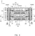
- the interconnector facing portion 146 in the lowermost electricity generation unit 102 is in contact with the lower end plate 106. Since the anode-side current collector 144 is thus configured, the anode-side current collector 144 electrically connects the anode 116 and the interconnector 150 (or the end plate 106) to each other.
- a spacer 149 formed of, for example, mica is disposed between the electrode facing portion 145 and the interconnector facing portion 146.
- the anode-side current collector 144 follows the deformation of the electricity generation unit 102 stemming from a temperature cycle and a pressure variation of reaction gas, thereby maintaining good electrical connection between the anode 116 and the interconnector 150 (or the end plate 106) via the anode-side current collector 144.
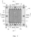
- each electricity generation unit 102 includes a felt member 41.
- the felt member 41 is disposed in the cathode chamber 166 at oppoiste ends in the direction (Y-axis direction) orthogonal to the main flow direction (X-axis direction) of the oxidizer gas OG (i.e., at a position not overlapping with the cathode 114 of the unit cell 110 in the Z-axis direction).
- the felt member 41 is disposed between the outer surface of the cathode-side current collector 134 and the wall surface of the hole 131 of the cathode-side frame 130 in the direction (Y-axis direction) orthogonal to the Z-axis direction. As shown in FIGS.
- the felt member 41 is also disposed in the anode chamber 176 at opposite ends in the direction (X-axis direction) orthogonal to the main flow direction (Y-axis direction) of the fuel gas FG (i.e., at a position not overlapping with the cathode 114 of the unit cell 110 in the Z-axis direction). Specifically, the felt member 41 is disposed between the outer surface of the anode-side current collector 144 and the wall surface of the hole 141 of the anode-side frame 140 in the direction (X-axis direction) orthogonal to the Z-axis direction.
- the presence of the felt member 41 prevents discharge of the oxidizer gas OG (supplied to the cathode chamber 166) or the fuel gas FG (supplied to the anode chamber 176) from the cathode chamber 166 or the anode chamber 176 through a region that less contributes to electricity generation, to thereby improve electricity generation performance.
- the cathode 114 or the anode 116 in the present embodiment corresponds to the specific electrode appearing in the claims.
- the cathode-side frame 130 or the anode-side frame 140 in the present embodiment corresponds to the frame member appearing in the claims.
- the cathode-side current collector 134 or the anode-side current collector 144 in the present embodiment corresponds to the current collecting member appearing in the claims.
- a plurality of the electricity generation units 102 contained in the fuel cell stack 100 are connected electrically in series. Accordingly, electric energy generated in the electricity generation units 102 is output from the end plates 104 and 106 which function as output terminals of the fuel cell stack 100.
- the fuel cell stack 100 may be heated by a heater (not shown) from startup until the high temperature can be maintained by means of heat generated as a result of generation of electricity.
- the fuel cell stack 100 has a structure including a plurality of stacked flat-plate-shaped electricity generation units 102.
- the present invention may be applied to another structure; for example, a structure disclosed in International Patent Publication WO 2012/165409 wherein a plurality of approximately cylindrical fuel cell unit cells are connected in series.
Landscapes
- Chemical & Material Sciences (AREA)
- Engineering & Computer Science (AREA)
- Electrochemistry (AREA)
- Chemical Kinetics & Catalysis (AREA)
- Sustainable Development (AREA)
- Sustainable Energy (AREA)
- Life Sciences & Earth Sciences (AREA)
- Manufacturing & Machinery (AREA)
- General Chemical & Material Sciences (AREA)
- Materials Engineering (AREA)
- Metallurgy (AREA)
- Organic Chemistry (AREA)
- Inorganic Chemistry (AREA)
- Fuel Cell (AREA)
Claims (7)
- Unité de réaction électrochimique (102), comprenant :une cellule unitaire (110) incluant une couche d'électrolyte (112), et une cathode (114) et une anode (116) qui se font face dans une première direction, la couche d'électrolyte (112) intervenant entre celles-ci ; etun élément feutre (41) contenant un matériau céramique et un composant silice, l'unité de réaction électrochimique (102) étant caractérisée en ce que :l'élément feutre (41) inclut à la fois une première structure cristalline correspondant au matériau céramique et une seconde structure cristalline, qui est une structure cristalline SiO2, correspondant au composant silice,dans laquelle l'élément feutre (41) est disposé dans une chambre de gaz (166, 176) faisant face à une électrode spécifique (114, 116), qui est au moins une de la cathode (114) et de l'anode (116).
- Unité de réaction électrochimique (102) selon la revendication 1, dans laquelle l'élément feutre (41) est disposé dans la chambre de gaz (166, 176) faisant face à l'électrode spécifique (114, 116) pour être situé à des extrémités opposées de la chambre de gaz dans une direction orthogonale à une direction principale d'écoulement d'un gaz.
- Unité de réaction électrochimique (102) selon la revendication 1 ou 2, l'unité de réaction électrochimique (102) comprenant en outre :un élément bâti (130, 140) ayant un trou (131, 141) formant la chambre de gaz (166, 176) faisant face à l'électrode spécifique (114, 116) ; etun élément collecteur de courant (134, 144) électriquement connecté à l'électrode spécifique (114, 116), dans laquelle :
l'élément feutre (41) est disposé entre une surface extérieure de l'élément collecteur de courant (134, 144) et une surface de paroi du trou (131, 141) de l'élément bâti (130, 140) dans une direction orthogonale à la première direction (direction d'axe Z). - Unité de réaction électrochimique (102) selon l'une quelconque des revendications 1 à 3, dans laquelle l'élément feutre (41) contient de l'alumine en tant que matériau céramique .
- Unité de réaction électrochimique (102) selon l'une quelconque des revendications 1 à 4, dans laquelle l'unité de réaction électrochimique (102) est une unité de génération d'électricité à pile à combustible (102).
- Empilement de cellules de réaction électrochimique (100) comprenant une pluralité d'unités de réaction électrochimique (102) disposées dans la première direction (direction d'axe Z), l'empilement de cellules de réaction électrochimique (100) étant caractérisé en ce que :
au moins une des unités de réaction électrochimique (102) est une unité de réaction électrochimique (102) telle que décrite dans l'une quelconque des revendications 1 à 5. - Procédé pour produire une unité de réaction électrochimique (102) comprenant une cellule unitaire (110) incluant une couche d'électrolyte (112), et une cathode (114) et une anode (116) qui se font face dans une première direction, la couche d'électrolyte (112) intervenant entre celles-ci, et un élément feutre (41) contenant un matériau céramique et un composant silice, caractérisé en ce que l'élément feutre (41) inclut à la fois une première structure cristalline correspondant au matériau céramique et une seconde structure cristalline, qui est une structure cristalline SiO2, correspondant au composant silice, le procédé comprenant les étapes de :la fourniture d'un matériau brut feutre contenant un matériau céramique et un composant silice ; etle traitement thermique du matériau brut feutre à 1 000 °C ou plus, ainsi formant l'élément feutre (41),dans lequel l'élément feutre (41) est disposé dans une chambre de gaz (166, 176) faisant face à une électrode spécifique (114, 116), qui est au moins une de la cathode (114) et de l'anode (116).
Applications Claiming Priority (2)
| Application Number | Priority Date | Filing Date | Title |
|---|---|---|---|
| JP2017034322 | 2017-02-27 | ||
| PCT/JP2018/003129 WO2018155111A1 (fr) | 2017-02-27 | 2018-01-31 | Unité de réaction électrochimique, empilement de cellules de réaction électrochimique, et procédé de production pour unité de réaction électrochimique |
Publications (3)
| Publication Number | Publication Date |
|---|---|
| EP3588643A1 EP3588643A1 (fr) | 2020-01-01 |
| EP3588643A4 EP3588643A4 (fr) | 2021-01-13 |
| EP3588643B1 true EP3588643B1 (fr) | 2024-07-03 |
Family
ID=63253666
Family Applications (1)
| Application Number | Title | Priority Date | Filing Date |
|---|---|---|---|
| EP18757019.7A Active EP3588643B1 (fr) | 2017-02-27 | 2018-01-31 | Unité de réaction électrochimique, empilement de cellules de réaction électrochimique, et procédé de production pour unité de réaction électrochimique |
Country Status (7)
| Country | Link |
|---|---|
| US (1) | US11289727B2 (fr) |
| EP (1) | EP3588643B1 (fr) |
| JP (1) | JP6573719B2 (fr) |
| KR (1) | KR102254281B1 (fr) |
| CN (1) | CN110337747B (fr) |
| DK (1) | DK3588643T3 (fr) |
| WO (1) | WO2018155111A1 (fr) |
Citations (2)
| Publication number | Priority date | Publication date | Assignee | Title |
|---|---|---|---|---|
| US20050266288A1 (en) * | 2004-05-27 | 2005-12-01 | Siemens Westinghouse Power Corporation | Flexible ceramic gasket for SOFC generator |
| US20140170522A1 (en) * | 2011-08-09 | 2014-06-19 | Ngk Spark Plug Co., Ltd. | Fuel cell and fuel cell stack |
Family Cites Families (22)
| Publication number | Priority date | Publication date | Assignee | Title |
|---|---|---|---|---|
| US4791035A (en) * | 1987-12-10 | 1988-12-13 | Westinghouse Electric Corp. | Cell and current collector felt arrangement for solid oxide electrochemical cell combinations |
| JPH02242564A (ja) * | 1989-03-15 | 1990-09-26 | Sanyo Electric Co Ltd | 固体電解質燃料電池 |
| JP2693676B2 (ja) | 1991-12-12 | 1997-12-24 | 日本碍子株式会社 | 発電装置 |
| US5292599A (en) | 1991-09-27 | 1994-03-08 | Ngk Insulators, Ltd. | Cell units for solid oxide fuel cells and power generators using such cell units |
| JPH05101836A (ja) * | 1991-10-09 | 1993-04-23 | Osaka Gas Co Ltd | 固体電解質型燃料電池 |
| JPH0636783A (ja) | 1992-07-17 | 1994-02-10 | Mitsubishi Heavy Ind Ltd | 平板型固体電解質燃料電池用燃料極集電材 |
| JP3150807B2 (ja) * | 1993-01-28 | 2001-03-26 | 三井造船株式会社 | 固体電解質型燃料電池スタックの接合材およびその製造方法 |
| US5856035A (en) * | 1996-02-29 | 1999-01-05 | Gas Research Institute | Electrical connector apparatus for planar solid oxide fuel cell stacks |
| DE60141634D1 (de) | 2000-08-18 | 2010-05-06 | Versa Power Systems Ltd | Hochtemperaturbeständige gasdichtungen |
| JP2005166455A (ja) | 2003-12-03 | 2005-06-23 | Nissan Motor Co Ltd | 固体酸化物形燃料電池用セル、セル板及びその製造方法 |
| JP4920958B2 (ja) * | 2005-11-22 | 2012-04-18 | 株式会社日立製作所 | 固体酸化物形燃料電池及びその製作方法 |
| US20070281194A1 (en) * | 2006-05-31 | 2007-12-06 | Jeffrey Earl Cortright | Portable fuel cell assembly |
| JP5242971B2 (ja) * | 2007-08-08 | 2013-07-24 | 日本特殊陶業株式会社 | 固体電解質型燃料電池 |
| JP5274607B2 (ja) | 2011-03-14 | 2013-08-28 | イビデン株式会社 | 触媒コンバータ用保持シール材及び触媒コンバータ |
| US9627697B2 (en) | 2011-05-30 | 2017-04-18 | Kyocera Corporation | Solid oxide fuel cell, fuel cell stack system, fuel cell module, and fuel cell system |
| DK2953197T3 (en) * | 2013-01-31 | 2018-09-24 | Ngk Spark Plug Co | Fuel cell and fuel cell stack |
| CN104969393B (zh) * | 2013-01-31 | 2017-12-05 | 日本特殊陶业株式会社 | 燃料电池单元和燃料电池堆 |
| EP2955778B1 (fr) * | 2013-02-07 | 2017-04-19 | NGK Sparkplug Co., Ltd. | Pile à combustible |
| JP6141753B2 (ja) * | 2013-11-06 | 2017-06-07 | 日本特殊陶業株式会社 | 固体酸化物形燃料電池 |
| JP6039110B2 (ja) * | 2014-01-15 | 2016-12-07 | 日本特殊陶業株式会社 | 固体酸化物形燃料電池用の燃料電池カセット及び燃料電池スタック |
| JP6317222B2 (ja) * | 2014-09-22 | 2018-04-25 | 日本特殊陶業株式会社 | 固体酸化物形燃料電池スタック |
| JP6385788B2 (ja) | 2014-10-20 | 2018-09-05 | 株式会社東芝 | 電気化学セルスタック、および電力システム |
-
2018
- 2018-01-31 WO PCT/JP2018/003129 patent/WO2018155111A1/fr not_active Ceased
- 2018-01-31 JP JP2018517910A patent/JP6573719B2/ja active Active
- 2018-01-31 CN CN201880014234.8A patent/CN110337747B/zh active Active
- 2018-01-31 EP EP18757019.7A patent/EP3588643B1/fr active Active
- 2018-01-31 KR KR1020197024925A patent/KR102254281B1/ko active Active
- 2018-01-31 DK DK18757019.7T patent/DK3588643T3/da active
- 2018-01-31 US US16/488,819 patent/US11289727B2/en active Active
Patent Citations (2)
| Publication number | Priority date | Publication date | Assignee | Title |
|---|---|---|---|---|
| US20050266288A1 (en) * | 2004-05-27 | 2005-12-01 | Siemens Westinghouse Power Corporation | Flexible ceramic gasket for SOFC generator |
| US20140170522A1 (en) * | 2011-08-09 | 2014-06-19 | Ngk Spark Plug Co., Ltd. | Fuel cell and fuel cell stack |
Also Published As
| Publication number | Publication date |
|---|---|
| JP6573719B2 (ja) | 2019-09-11 |
| KR20190111092A (ko) | 2019-10-01 |
| EP3588643A1 (fr) | 2020-01-01 |
| KR102254281B1 (ko) | 2021-05-21 |
| CN110337747A (zh) | 2019-10-15 |
| DK3588643T3 (da) | 2024-07-22 |
| US11289727B2 (en) | 2022-03-29 |
| JPWO2018155111A1 (ja) | 2019-02-28 |
| CN110337747B (zh) | 2022-08-02 |
| WO2018155111A1 (fr) | 2018-08-30 |
| US20210135262A1 (en) | 2021-05-06 |
| EP3588643A4 (fr) | 2021-01-13 |
Similar Documents
| Publication | Publication Date | Title |
|---|---|---|
| EP3588644B1 (fr) | Unité de réaction électrochimique et empilement de cellules de réaction électrochimique | |
| JP7079220B2 (ja) | 電気化学反応セルスタック | |
| US11223060B2 (en) | Electrochemical reaction single cell and electrochemical reaction cell stack | |
| US20160372758A1 (en) | Electrochemical reaction unit and fuel cell stack | |
| EP3547428A1 (fr) | Unité de réaction électrochimique, empilement de cellules de réaction électrochimique, et procédé de production d'unité de réaction électrochimique | |
| US20190288322A1 (en) | Electrochemical cell stack | |
| EP3588643B1 (fr) | Unité de réaction électrochimique, empilement de cellules de réaction électrochimique, et procédé de production pour unité de réaction électrochimique | |
| EP3584865A1 (fr) | Cellule unique à réaction électrochimique et assemblage de cellules à réaction électrochimique | |
| JP2024058262A (ja) | 電気化学反応単セル | |
| JP6797150B2 (ja) | 電気化学反応単位、電気化学反応セルスタック、および、電気化学反応単位の製造方法 | |
| US10665872B2 (en) | Fuel cell stack and method for manufacturing fuel cell stack | |
| US10756375B2 (en) | Electrochemical reaction unit cell, and electrochemical reaction cell stack | |
| JP7654021B2 (ja) | 電気化学反応単位、および電気化学反応装置の製造方法 | |
| JP2018174039A (ja) | 電気化学反応単位および電気化学反応セルスタック | |
| US11027982B2 (en) | Mica-made member, electrochemical reaction unit, and electrochemical reaction cell stack | |
| JP2018113127A (ja) | 電気化学反応セルスタックの製造方法 | |
| JP2025097557A (ja) | 電気化学反応セル用部材、および、電気化学反応セルスタック | |
| JP2018174041A (ja) | 電気化学反応単位および電気化学反応セルスタック | |
| JP2018174040A (ja) | 電気化学反応単位および電気化学反応セルスタック |
Legal Events
| Date | Code | Title | Description |
|---|---|---|---|
| STAA | Information on the status of an ep patent application or granted ep patent |
Free format text: STATUS: THE INTERNATIONAL PUBLICATION HAS BEEN MADE |
|
| PUAI | Public reference made under article 153(3) epc to a published international application that has entered the european phase |
Free format text: ORIGINAL CODE: 0009012 |
|
| STAA | Information on the status of an ep patent application or granted ep patent |
Free format text: STATUS: REQUEST FOR EXAMINATION WAS MADE |
|
| 17P | Request for examination filed |
Effective date: 20190827 |
|
| AK | Designated contracting states |
Kind code of ref document: A1 Designated state(s): AL AT BE BG CH CY CZ DE DK EE ES FI FR GB GR HR HU IE IS IT LI LT LU LV MC MK MT NL NO PL PT RO RS SE SI SK SM TR |
|
| AX | Request for extension of the european patent |
Extension state: BA ME |
|
| RAP1 | Party data changed (applicant data changed or rights of an application transferred) |
Owner name: MORIMURA SOFC TECHNOLOGY CO., LTD. |
|
| DAV | Request for validation of the european patent (deleted) | ||
| DAX | Request for extension of the european patent (deleted) | ||
| A4 | Supplementary search report drawn up and despatched |
Effective date: 20201211 |
|
| RIC1 | Information provided on ipc code assigned before grant |
Ipc: C25B 1/08 20060101ALI20201207BHEP Ipc: H01M 8/0282 20160101ALI20201207BHEP Ipc: H01M 8/0276 20160101ALI20201207BHEP Ipc: C25B 13/04 20060101ALI20201207BHEP Ipc: C25B 9/00 20060101ALI20201207BHEP Ipc: H01M 8/2432 20160101ALI20201207BHEP Ipc: C25B 9/20 20060101ALI20201207BHEP Ipc: H01M 8/242 20160101ALI20201207BHEP Ipc: H01M 8/02 20160101AFI20201207BHEP Ipc: H01M 8/0273 20160101ALI20201207BHEP Ipc: H01M 8/12 20160101ALI20201207BHEP Ipc: H01M 8/0286 20160101ALI20201207BHEP Ipc: H01M 8/124 20160101ALI20201207BHEP |
|
| REG | Reference to a national code |
Ref legal event code: R079 Ipc: H01M0008027300 Ref country code: DE Ref legal event code: R079 Ref document number: 602018071304 Country of ref document: DE Free format text: PREVIOUS MAIN CLASS: H01M0008020000 Ipc: H01M0008027300 |
|
| RIC1 | Information provided on ipc code assigned before grant |
Ipc: H01M 8/12 20160101ALN20231206BHEP Ipc: C25B 9/77 20210101ALI20231206BHEP Ipc: C25B 9/73 20210101ALI20231206BHEP Ipc: C25B 1/04 20060101ALI20231206BHEP Ipc: C25B 9/00 20060101ALI20231206BHEP Ipc: H01M 8/2432 20160101ALI20231206BHEP Ipc: H01M 8/242 20160101ALI20231206BHEP Ipc: H01M 8/0286 20160101ALI20231206BHEP Ipc: H01M 8/0282 20160101ALI20231206BHEP Ipc: H01M 8/0276 20160101ALI20231206BHEP Ipc: H01M 8/0273 20160101AFI20231206BHEP |
|
| GRAJ | Information related to disapproval of communication of intention to grant by the applicant or resumption of examination proceedings by the epo deleted |
Free format text: ORIGINAL CODE: EPIDOSDIGR1 |
|
| STAA | Information on the status of an ep patent application or granted ep patent |
Free format text: STATUS: GRANT OF PATENT IS INTENDED |
|
| GRAP | Despatch of communication of intention to grant a patent |
Free format text: ORIGINAL CODE: EPIDOSNIGR1 |
|
| INTG | Intention to grant announced |
Effective date: 20240122 |
|
| RIN1 | Information on inventor provided before grant (corrected) |
Inventor name: ONO, TATSUYA Inventor name: ISHIDA, SATORU |
|
| GRAS | Grant fee paid |
Free format text: ORIGINAL CODE: EPIDOSNIGR3 |
|
| GRAA | (expected) grant |
Free format text: ORIGINAL CODE: 0009210 |
|
| STAA | Information on the status of an ep patent application or granted ep patent |
Free format text: STATUS: THE PATENT HAS BEEN GRANTED |
|
| RAP1 | Party data changed (applicant data changed or rights of an application transferred) |
Owner name: NITERRA CO., LTD. |
|
| AK | Designated contracting states |
Kind code of ref document: B1 Designated state(s): AL AT BE BG CH CY CZ DE DK EE ES FI FR GB GR HR HU IE IS IT LI LT LU LV MC MK MT NL NO PL PT RO RS SE SI SK SM TR |
|
| REG | Reference to a national code |
Ref country code: CH Ref legal event code: EP |
|
| REG | Reference to a national code |
Ref country code: DE Ref legal event code: R096 Ref document number: 602018071304 Country of ref document: DE |
|
| REG | Reference to a national code |
Ref country code: DK Ref legal event code: T3 Effective date: 20240717 |
|
| REG | Reference to a national code |
Ref country code: EE Ref legal event code: FG4A Ref document number: E024523 Country of ref document: EE Effective date: 20240731 |
|
| REG | Reference to a national code |
Ref country code: LT Ref legal event code: MG9D |
|
| REG | Reference to a national code |
Ref country code: NL Ref legal event code: MP Effective date: 20240703 |
|
| PG25 | Lapsed in a contracting state [announced via postgrant information from national office to epo] |
Ref country code: PT Free format text: LAPSE BECAUSE OF FAILURE TO SUBMIT A TRANSLATION OF THE DESCRIPTION OR TO PAY THE FEE WITHIN THE PRESCRIBED TIME-LIMIT Effective date: 20241104 |
|
| REG | Reference to a national code |
Ref country code: AT Ref legal event code: MK05 Ref document number: 1700767 Country of ref document: AT Kind code of ref document: T Effective date: 20240703 |
|
| PG25 | Lapsed in a contracting state [announced via postgrant information from national office to epo] |
Ref country code: NL Free format text: LAPSE BECAUSE OF FAILURE TO SUBMIT A TRANSLATION OF THE DESCRIPTION OR TO PAY THE FEE WITHIN THE PRESCRIBED TIME-LIMIT Effective date: 20240703 |
|
| PG25 | Lapsed in a contracting state [announced via postgrant information from national office to epo] |
Ref country code: PT Free format text: LAPSE BECAUSE OF FAILURE TO SUBMIT A TRANSLATION OF THE DESCRIPTION OR TO PAY THE FEE WITHIN THE PRESCRIBED TIME-LIMIT Effective date: 20241104 Ref country code: NL Free format text: LAPSE BECAUSE OF FAILURE TO SUBMIT A TRANSLATION OF THE DESCRIPTION OR TO PAY THE FEE WITHIN THE PRESCRIBED TIME-LIMIT Effective date: 20240703 |
|
| PG25 | Lapsed in a contracting state [announced via postgrant information from national office to epo] |
Ref country code: NO Free format text: LAPSE BECAUSE OF FAILURE TO SUBMIT A TRANSLATION OF THE DESCRIPTION OR TO PAY THE FEE WITHIN THE PRESCRIBED TIME-LIMIT Effective date: 20241003 |
|
| PG25 | Lapsed in a contracting state [announced via postgrant information from national office to epo] |
Ref country code: FI Free format text: LAPSE BECAUSE OF FAILURE TO SUBMIT A TRANSLATION OF THE DESCRIPTION OR TO PAY THE FEE WITHIN THE PRESCRIBED TIME-LIMIT Effective date: 20240703 Ref country code: GR Free format text: LAPSE BECAUSE OF FAILURE TO SUBMIT A TRANSLATION OF THE DESCRIPTION OR TO PAY THE FEE WITHIN THE PRESCRIBED TIME-LIMIT Effective date: 20241004 Ref country code: PL Free format text: LAPSE BECAUSE OF FAILURE TO SUBMIT A TRANSLATION OF THE DESCRIPTION OR TO PAY THE FEE WITHIN THE PRESCRIBED TIME-LIMIT Effective date: 20240703 |
|
| PG25 | Lapsed in a contracting state [announced via postgrant information from national office to epo] |
Ref country code: BG Free format text: LAPSE BECAUSE OF FAILURE TO SUBMIT A TRANSLATION OF THE DESCRIPTION OR TO PAY THE FEE WITHIN THE PRESCRIBED TIME-LIMIT Effective date: 20240703 |
|
| PG25 | Lapsed in a contracting state [announced via postgrant information from national office to epo] |
Ref country code: LV Free format text: LAPSE BECAUSE OF FAILURE TO SUBMIT A TRANSLATION OF THE DESCRIPTION OR TO PAY THE FEE WITHIN THE PRESCRIBED TIME-LIMIT Effective date: 20240703 |
|
| PG25 | Lapsed in a contracting state [announced via postgrant information from national office to epo] |
Ref country code: IS Free format text: LAPSE BECAUSE OF FAILURE TO SUBMIT A TRANSLATION OF THE DESCRIPTION OR TO PAY THE FEE WITHIN THE PRESCRIBED TIME-LIMIT Effective date: 20241103 Ref country code: AT Free format text: LAPSE BECAUSE OF FAILURE TO SUBMIT A TRANSLATION OF THE DESCRIPTION OR TO PAY THE FEE WITHIN THE PRESCRIBED TIME-LIMIT Effective date: 20240703 |
|
| PG25 | Lapsed in a contracting state [announced via postgrant information from national office to epo] |
Ref country code: HR Free format text: LAPSE BECAUSE OF FAILURE TO SUBMIT A TRANSLATION OF THE DESCRIPTION OR TO PAY THE FEE WITHIN THE PRESCRIBED TIME-LIMIT Effective date: 20240703 Ref country code: CZ Free format text: LAPSE BECAUSE OF FAILURE TO SUBMIT A TRANSLATION OF THE DESCRIPTION OR TO PAY THE FEE WITHIN THE PRESCRIBED TIME-LIMIT Effective date: 20240703 |
|
| PG25 | Lapsed in a contracting state [announced via postgrant information from national office to epo] |
Ref country code: RS Free format text: LAPSE BECAUSE OF FAILURE TO SUBMIT A TRANSLATION OF THE DESCRIPTION OR TO PAY THE FEE WITHIN THE PRESCRIBED TIME-LIMIT Effective date: 20241003 Ref country code: ES Free format text: LAPSE BECAUSE OF FAILURE TO SUBMIT A TRANSLATION OF THE DESCRIPTION OR TO PAY THE FEE WITHIN THE PRESCRIBED TIME-LIMIT Effective date: 20240703 |
|
| PG25 | Lapsed in a contracting state [announced via postgrant information from national office to epo] |
Ref country code: RS Free format text: LAPSE BECAUSE OF FAILURE TO SUBMIT A TRANSLATION OF THE DESCRIPTION OR TO PAY THE FEE WITHIN THE PRESCRIBED TIME-LIMIT Effective date: 20241003 Ref country code: PL Free format text: LAPSE BECAUSE OF FAILURE TO SUBMIT A TRANSLATION OF THE DESCRIPTION OR TO PAY THE FEE WITHIN THE PRESCRIBED TIME-LIMIT Effective date: 20240703 Ref country code: NO Free format text: LAPSE BECAUSE OF FAILURE TO SUBMIT A TRANSLATION OF THE DESCRIPTION OR TO PAY THE FEE WITHIN THE PRESCRIBED TIME-LIMIT Effective date: 20241003 Ref country code: LV Free format text: LAPSE BECAUSE OF FAILURE TO SUBMIT A TRANSLATION OF THE DESCRIPTION OR TO PAY THE FEE WITHIN THE PRESCRIBED TIME-LIMIT Effective date: 20240703 Ref country code: IS Free format text: LAPSE BECAUSE OF FAILURE TO SUBMIT A TRANSLATION OF THE DESCRIPTION OR TO PAY THE FEE WITHIN THE PRESCRIBED TIME-LIMIT Effective date: 20241103 Ref country code: HR Free format text: LAPSE BECAUSE OF FAILURE TO SUBMIT A TRANSLATION OF THE DESCRIPTION OR TO PAY THE FEE WITHIN THE PRESCRIBED TIME-LIMIT Effective date: 20240703 Ref country code: GR Free format text: LAPSE BECAUSE OF FAILURE TO SUBMIT A TRANSLATION OF THE DESCRIPTION OR TO PAY THE FEE WITHIN THE PRESCRIBED TIME-LIMIT Effective date: 20241004 Ref country code: FI Free format text: LAPSE BECAUSE OF FAILURE TO SUBMIT A TRANSLATION OF THE DESCRIPTION OR TO PAY THE FEE WITHIN THE PRESCRIBED TIME-LIMIT Effective date: 20240703 Ref country code: ES Free format text: LAPSE BECAUSE OF FAILURE TO SUBMIT A TRANSLATION OF THE DESCRIPTION OR TO PAY THE FEE WITHIN THE PRESCRIBED TIME-LIMIT Effective date: 20240703 Ref country code: CZ Free format text: LAPSE BECAUSE OF FAILURE TO SUBMIT A TRANSLATION OF THE DESCRIPTION OR TO PAY THE FEE WITHIN THE PRESCRIBED TIME-LIMIT Effective date: 20240703 Ref country code: BG Free format text: LAPSE BECAUSE OF FAILURE TO SUBMIT A TRANSLATION OF THE DESCRIPTION OR TO PAY THE FEE WITHIN THE PRESCRIBED TIME-LIMIT Effective date: 20240703 Ref country code: AT Free format text: LAPSE BECAUSE OF FAILURE TO SUBMIT A TRANSLATION OF THE DESCRIPTION OR TO PAY THE FEE WITHIN THE PRESCRIBED TIME-LIMIT Effective date: 20240703 |
|
| REG | Reference to a national code |
Ref country code: DE Ref legal event code: R097 Ref document number: 602018071304 Country of ref document: DE |
|
| PG25 | Lapsed in a contracting state [announced via postgrant information from national office to epo] |
Ref country code: RO Free format text: LAPSE BECAUSE OF FAILURE TO SUBMIT A TRANSLATION OF THE DESCRIPTION OR TO PAY THE FEE WITHIN THE PRESCRIBED TIME-LIMIT Effective date: 20240703 Ref country code: SM Free format text: LAPSE BECAUSE OF FAILURE TO SUBMIT A TRANSLATION OF THE DESCRIPTION OR TO PAY THE FEE WITHIN THE PRESCRIBED TIME-LIMIT Effective date: 20240703 |
|
| PG25 | Lapsed in a contracting state [announced via postgrant information from national office to epo] |
Ref country code: SK Free format text: LAPSE BECAUSE OF FAILURE TO SUBMIT A TRANSLATION OF THE DESCRIPTION OR TO PAY THE FEE WITHIN THE PRESCRIBED TIME-LIMIT Effective date: 20240703 Ref country code: IT Free format text: LAPSE BECAUSE OF FAILURE TO SUBMIT A TRANSLATION OF THE DESCRIPTION OR TO PAY THE FEE WITHIN THE PRESCRIBED TIME-LIMIT Effective date: 20240703 |
|
| PLBE | No opposition filed within time limit |
Free format text: ORIGINAL CODE: 0009261 |
|
| STAA | Information on the status of an ep patent application or granted ep patent |
Free format text: STATUS: NO OPPOSITION FILED WITHIN TIME LIMIT |
|
| 26N | No opposition filed |
Effective date: 20250404 |
|
| REG | Reference to a national code |
Ref country code: CH Ref legal event code: PL |
|
| PG25 | Lapsed in a contracting state [announced via postgrant information from national office to epo] |
Ref country code: SE Free format text: LAPSE BECAUSE OF FAILURE TO SUBMIT A TRANSLATION OF THE DESCRIPTION OR TO PAY THE FEE WITHIN THE PRESCRIBED TIME-LIMIT Effective date: 20240703 |
|
| PG25 | Lapsed in a contracting state [announced via postgrant information from national office to epo] |
Ref country code: LU Free format text: LAPSE BECAUSE OF NON-PAYMENT OF DUE FEES Effective date: 20250131 Ref country code: MC Free format text: LAPSE BECAUSE OF FAILURE TO SUBMIT A TRANSLATION OF THE DESCRIPTION OR TO PAY THE FEE WITHIN THE PRESCRIBED TIME-LIMIT Effective date: 20240703 |
|
| GBPC | Gb: european patent ceased through non-payment of renewal fee |
Effective date: 20250131 |
|
| PG25 | Lapsed in a contracting state [announced via postgrant information from national office to epo] |
Ref country code: GB Free format text: LAPSE BECAUSE OF NON-PAYMENT OF DUE FEES Effective date: 20250131 Ref country code: BE Free format text: LAPSE BECAUSE OF NON-PAYMENT OF DUE FEES Effective date: 20250131 |
|
| PG25 | Lapsed in a contracting state [announced via postgrant information from national office to epo] |
Ref country code: FR Free format text: LAPSE BECAUSE OF NON-PAYMENT OF DUE FEES Effective date: 20250131 |
|
| PG25 | Lapsed in a contracting state [announced via postgrant information from national office to epo] |
Ref country code: CH Free format text: LAPSE BECAUSE OF NON-PAYMENT OF DUE FEES Effective date: 20250131 |
|
| REG | Reference to a national code |
Ref country code: BE Ref legal event code: MM Effective date: 20250131 |
|
| PG25 | Lapsed in a contracting state [announced via postgrant information from national office to epo] |
Ref country code: IE Free format text: LAPSE BECAUSE OF NON-PAYMENT OF DUE FEES Effective date: 20250131 |
|
| PGFP | Annual fee paid to national office [announced via postgrant information from national office to epo] |
Ref country code: EE Payment date: 20251229 Year of fee payment: 9 |
|
| PGFP | Annual fee paid to national office [announced via postgrant information from national office to epo] |
Ref country code: DK Payment date: 20260113 Year of fee payment: 9 Ref country code: DE Payment date: 20251210 Year of fee payment: 9 |