WO2018155111A1 - Unité de réaction électrochimique, empilement de cellules de réaction électrochimique, et procédé de production pour unité de réaction électrochimique - Google Patents
Unité de réaction électrochimique, empilement de cellules de réaction électrochimique, et procédé de production pour unité de réaction électrochimique Download PDFInfo
- Publication number
- WO2018155111A1 WO2018155111A1 PCT/JP2018/003129 JP2018003129W WO2018155111A1 WO 2018155111 A1 WO2018155111 A1 WO 2018155111A1 JP 2018003129 W JP2018003129 W JP 2018003129W WO 2018155111 A1 WO2018155111 A1 WO 2018155111A1
- Authority
- WO
- WIPO (PCT)
- Prior art keywords
- electrochemical reaction
- reaction unit
- fuel
- felt
- crystal structure
- Prior art date
- Legal status (The legal status is an assumption and is not a legal conclusion. Google has not performed a legal analysis and makes no representation as to the accuracy of the status listed.)
- Ceased
Links
Images



Classifications
-
- H—ELECTRICITY
- H01—ELECTRIC ELEMENTS
- H01M—PROCESSES OR MEANS, e.g. BATTERIES, FOR THE DIRECT CONVERSION OF CHEMICAL ENERGY INTO ELECTRICAL ENERGY
- H01M8/00—Fuel cells; Manufacture thereof
- H01M8/06—Combination of fuel cells with means for production of reactants or for treatment of residues
- H01M8/0662—Treatment of gaseous reactants or gaseous residues, e.g. cleaning
-
- C—CHEMISTRY; METALLURGY
- C25—ELECTROLYTIC OR ELECTROPHORETIC PROCESSES; APPARATUS THEREFOR
- C25B—ELECTROLYTIC OR ELECTROPHORETIC PROCESSES FOR THE PRODUCTION OF COMPOUNDS OR NON-METALS; APPARATUS THEREFOR
- C25B1/00—Electrolytic production of inorganic compounds or non-metals
- C25B1/01—Products
- C25B1/02—Hydrogen or oxygen
- C25B1/04—Hydrogen or oxygen by electrolysis of water
-
- C—CHEMISTRY; METALLURGY
- C25—ELECTROLYTIC OR ELECTROPHORETIC PROCESSES; APPARATUS THEREFOR
- C25B—ELECTROLYTIC OR ELECTROPHORETIC PROCESSES FOR THE PRODUCTION OF COMPOUNDS OR NON-METALS; APPARATUS THEREFOR
- C25B13/00—Diaphragms; Spacing elements
- C25B13/04—Diaphragms; Spacing elements characterised by the material
-
- C—CHEMISTRY; METALLURGY
- C25—ELECTROLYTIC OR ELECTROPHORETIC PROCESSES; APPARATUS THEREFOR
- C25B—ELECTROLYTIC OR ELECTROPHORETIC PROCESSES FOR THE PRODUCTION OF COMPOUNDS OR NON-METALS; APPARATUS THEREFOR
- C25B9/00—Cells or assemblies of cells; Constructional parts of cells; Assemblies of constructional parts, e.g. electrode-diaphragm assemblies; Process-related cell features
-
- C—CHEMISTRY; METALLURGY
- C25—ELECTROLYTIC OR ELECTROPHORETIC PROCESSES; APPARATUS THEREFOR
- C25B—ELECTROLYTIC OR ELECTROPHORETIC PROCESSES FOR THE PRODUCTION OF COMPOUNDS OR NON-METALS; APPARATUS THEREFOR
- C25B9/00—Cells or assemblies of cells; Constructional parts of cells; Assemblies of constructional parts, e.g. electrode-diaphragm assemblies; Process-related cell features
- C25B9/70—Assemblies comprising two or more cells
- C25B9/73—Assemblies comprising two or more cells of the filter-press type
-
- C—CHEMISTRY; METALLURGY
- C25—ELECTROLYTIC OR ELECTROPHORETIC PROCESSES; APPARATUS THEREFOR
- C25B—ELECTROLYTIC OR ELECTROPHORETIC PROCESSES FOR THE PRODUCTION OF COMPOUNDS OR NON-METALS; APPARATUS THEREFOR
- C25B9/00—Cells or assemblies of cells; Constructional parts of cells; Assemblies of constructional parts, e.g. electrode-diaphragm assemblies; Process-related cell features
- C25B9/70—Assemblies comprising two or more cells
- C25B9/73—Assemblies comprising two or more cells of the filter-press type
- C25B9/77—Assemblies comprising two or more cells of the filter-press type having diaphragms
-
- H—ELECTRICITY
- H01—ELECTRIC ELEMENTS
- H01M—PROCESSES OR MEANS, e.g. BATTERIES, FOR THE DIRECT CONVERSION OF CHEMICAL ENERGY INTO ELECTRICAL ENERGY
- H01M8/00—Fuel cells; Manufacture thereof
- H01M8/02—Details
- H01M8/0271—Sealing or supporting means around electrodes, matrices or membranes
- H01M8/0273—Sealing or supporting means around electrodes, matrices or membranes with sealing or supporting means in the form of a frame
-
- H—ELECTRICITY
- H01—ELECTRIC ELEMENTS
- H01M—PROCESSES OR MEANS, e.g. BATTERIES, FOR THE DIRECT CONVERSION OF CHEMICAL ENERGY INTO ELECTRICAL ENERGY
- H01M8/00—Fuel cells; Manufacture thereof
- H01M8/02—Details
- H01M8/0271—Sealing or supporting means around electrodes, matrices or membranes
- H01M8/0276—Sealing means characterised by their form
-
- H—ELECTRICITY
- H01—ELECTRIC ELEMENTS
- H01M—PROCESSES OR MEANS, e.g. BATTERIES, FOR THE DIRECT CONVERSION OF CHEMICAL ENERGY INTO ELECTRICAL ENERGY
- H01M8/00—Fuel cells; Manufacture thereof
- H01M8/02—Details
- H01M8/0271—Sealing or supporting means around electrodes, matrices or membranes
- H01M8/028—Sealing means characterised by their material
- H01M8/0282—Inorganic material
-
- H—ELECTRICITY
- H01—ELECTRIC ELEMENTS
- H01M—PROCESSES OR MEANS, e.g. BATTERIES, FOR THE DIRECT CONVERSION OF CHEMICAL ENERGY INTO ELECTRICAL ENERGY
- H01M8/00—Fuel cells; Manufacture thereof
- H01M8/02—Details
- H01M8/0271—Sealing or supporting means around electrodes, matrices or membranes
- H01M8/0286—Processes for forming seals
-
- H—ELECTRICITY
- H01—ELECTRIC ELEMENTS
- H01M—PROCESSES OR MEANS, e.g. BATTERIES, FOR THE DIRECT CONVERSION OF CHEMICAL ENERGY INTO ELECTRICAL ENERGY
- H01M8/00—Fuel cells; Manufacture thereof
- H01M8/10—Fuel cells with solid electrolytes
- H01M8/12—Fuel cells with solid electrolytes operating at high temperature, e.g. with stabilised ZrO2 electrolyte
-
- H—ELECTRICITY
- H01—ELECTRIC ELEMENTS
- H01M—PROCESSES OR MEANS, e.g. BATTERIES, FOR THE DIRECT CONVERSION OF CHEMICAL ENERGY INTO ELECTRICAL ENERGY
- H01M8/00—Fuel cells; Manufacture thereof
- H01M8/24—Grouping of fuel cells, e.g. stacking of fuel cells
- H01M8/241—Grouping of fuel cells, e.g. stacking of fuel cells with solid or matrix-supported electrolytes
- H01M8/242—Grouping of fuel cells, e.g. stacking of fuel cells with solid or matrix-supported electrolytes comprising framed electrodes or intermediary frame-like gaskets
-
- H—ELECTRICITY
- H01—ELECTRIC ELEMENTS
- H01M—PROCESSES OR MEANS, e.g. BATTERIES, FOR THE DIRECT CONVERSION OF CHEMICAL ENERGY INTO ELECTRICAL ENERGY
- H01M8/00—Fuel cells; Manufacture thereof
- H01M8/24—Grouping of fuel cells, e.g. stacking of fuel cells
- H01M8/241—Grouping of fuel cells, e.g. stacking of fuel cells with solid or matrix-supported electrolytes
- H01M8/2425—High-temperature cells with solid electrolytes
- H01M8/2432—Grouping of unit cells of planar configuration
-
- H—ELECTRICITY
- H01—ELECTRIC ELEMENTS
- H01M—PROCESSES OR MEANS, e.g. BATTERIES, FOR THE DIRECT CONVERSION OF CHEMICAL ENERGY INTO ELECTRICAL ENERGY
- H01M8/00—Fuel cells; Manufacture thereof
- H01M8/10—Fuel cells with solid electrolytes
- H01M8/12—Fuel cells with solid electrolytes operating at high temperature, e.g. with stabilised ZrO2 electrolyte
- H01M2008/1293—Fuel cells with solid oxide electrolytes
-
- Y—GENERAL TAGGING OF NEW TECHNOLOGICAL DEVELOPMENTS; GENERAL TAGGING OF CROSS-SECTIONAL TECHNOLOGIES SPANNING OVER SEVERAL SECTIONS OF THE IPC; TECHNICAL SUBJECTS COVERED BY FORMER USPC CROSS-REFERENCE ART COLLECTIONS [XRACs] AND DIGESTS
- Y02—TECHNOLOGIES OR APPLICATIONS FOR MITIGATION OR ADAPTATION AGAINST CLIMATE CHANGE
- Y02E—REDUCTION OF GREENHOUSE GAS [GHG] EMISSIONS, RELATED TO ENERGY GENERATION, TRANSMISSION OR DISTRIBUTION
- Y02E60/00—Enabling technologies; Technologies with a potential or indirect contribution to GHG emissions mitigation
- Y02E60/30—Hydrogen technology
- Y02E60/36—Hydrogen production from non-carbon containing sources, e.g. by water electrolysis
-
- Y—GENERAL TAGGING OF NEW TECHNOLOGICAL DEVELOPMENTS; GENERAL TAGGING OF CROSS-SECTIONAL TECHNOLOGIES SPANNING OVER SEVERAL SECTIONS OF THE IPC; TECHNICAL SUBJECTS COVERED BY FORMER USPC CROSS-REFERENCE ART COLLECTIONS [XRACs] AND DIGESTS
- Y02—TECHNOLOGIES OR APPLICATIONS FOR MITIGATION OR ADAPTATION AGAINST CLIMATE CHANGE
- Y02E—REDUCTION OF GREENHOUSE GAS [GHG] EMISSIONS, RELATED TO ENERGY GENERATION, TRANSMISSION OR DISTRIBUTION
- Y02E60/00—Enabling technologies; Technologies with a potential or indirect contribution to GHG emissions mitigation
- Y02E60/30—Hydrogen technology
- Y02E60/50—Fuel cells
Definitions
- the technology disclosed by this specification relates to an electrochemical reaction unit.
- a solid oxide fuel cell (hereinafter referred to as “SOFC”) is known as one of fuel cells that generate electricity using an electrochemical reaction between hydrogen and oxygen.
- a fuel cell power generation unit (hereinafter referred to as “power generation unit”), which is a constituent unit of SOFC, includes a fuel cell single cell (hereinafter referred to as “single cell”).
- the single cell includes an electrolyte layer and an air electrode and a fuel electrode facing each other in a predetermined direction (hereinafter referred to as “first direction”) with the electrolyte layer interposed therebetween.
- a felt unit may be filled in the power generation unit for the purpose of improving the power generation efficiency by filling the space around the single cell.
- a felt member is required to have flexibility and heat resistance. Therefore, a felt member is comprised by the felt material (for example, nickel felt) containing a metal and the felt material (for example, alumina felt) containing ceramics (for example, refer patent document 1).
- Felt materials containing ceramics and felt materials containing metals may contain contaminants such as Si. For this reason, in the above-described conventional configuration, contaminants such as Si are scattered from the felt member, and there is a possibility that the performance of the single cell may be deteriorated due to poisoning by the contaminants.
- Such a problem is also a problem common to electrolytic cell units, which are constituent units of solid oxide electrolytic cells (hereinafter referred to as “SOEC”) that generate hydrogen using an electrolysis reaction of water. It is.
- SOEC solid oxide electrolytic cells
- the fuel cell power generation unit and the electrolysis cell unit are collectively referred to as an electrochemical reaction unit.
- Such a problem is not limited to SOFC and SOEC, but is common to other types of electrochemical reaction units.
- the electrochemical reaction unit disclosed in this specification includes a single cell including an electrolyte layer and an air electrode and a fuel electrode facing each other in a first direction with the electrolyte layer interposed therebetween, ceramics or metal and silica And a felt member including a component, wherein the felt member has a first crystal structure and a second crystal structure that is a crystal structure of SiO 2. Yes.
- the felt member since the felt member has the first crystal structure and the second crystal structure which is the crystal structure of SiO 2 , Si from the felt member can be obtained. And scattering of other contaminants can be suppressed, and the occurrence of deterioration in the performance of the single cell due to poisoning by Si and other contaminants can be suppressed.
- the felt member may be arranged in a gas chamber facing a specific electrode that is at least one of the air electrode and the fuel electrode. According to this electrochemical reaction unit, since the felt member is arranged in the gas chamber facing the specific electrode, the performance of the single cell is deteriorated due to poisoning by Si or other contaminants scattered from the felt member. In a configuration where the occurrence of odor is likely to occur, the scattering of Si and other pollutants from the felt member can be suppressed, and the deterioration of the performance of the single cell due to poisoning by Si and other pollutants can be suppressed. Can do.
- the felt member may be disposed at both ends of the gas chamber facing the specific electrode in a direction orthogonal to a main gas flow direction. According to the present electrochemical reaction unit, the presence of the felt member prevents the gas supplied to the gas chamber facing the specific electrode from passing through the region that does not contribute much to the reaction and being discharged from the gas chamber. While improving the reaction efficiency, it is possible to suppress the scattering of Si and other pollutants from the felt member, and to suppress the occurrence of degradation of the performance of the single cell due to poisoning by Si and other pollutants. Can do.
- the electrochemical reaction unit further includes a frame member in which a hole constituting the gas chamber facing the specific electrode is formed, and a current collecting member electrically connected to the specific electrode.
- the felt member may be arranged between an outer surface of the current collecting member and a surface of the hole in the frame member in a direction orthogonal to the first direction. According to the present electrochemical reaction unit, the presence of the felt member prevents the gas supplied to the gas chamber facing the specific electrode from passing through the region that does not contribute much to the reaction and being discharged from the gas chamber. While improving the reaction efficiency, it is possible to suppress the scattering of Si and other pollutants from the felt member, and to suppress the occurrence of degradation of the performance of the single cell due to poisoning by Si and other pollutants. Can do.
- the felt member may include alumina as the ceramic. According to this electrochemical reaction unit, the heat resistance and flexibility of the felt member can be improved while suppressing the scattering of Si and other contaminants from the felt member.
- the electrochemical reaction unit may be a fuel cell power generation unit. According to this electrochemical reaction unit, it is possible to suppress the occurrence of a decrease in power generation performance of the single cell due to poisoning by Si or other contaminants.
- the method for producing an electrochemical reaction unit disclosed in the present specification includes a single cell including an electrolyte layer and an air electrode and a fuel electrode facing each other in a first direction with the electrolyte layer interposed therebetween,
- a method for producing an electrochemical reaction unit comprising a felt member containing ceramics or metal and a silica component, a step of preparing a felt raw material containing ceramics or metal and a silica component, and heat-treating the felt raw material at 1000 ° C. or higher And forming the felt member.
- a felt member is prepared by heat-treating a felt raw material at 1000 ° C.
- the second crystal structure which is a structure, can provide a felt member with less scattering of Si and other pollutants, and the performance of the unit cell due to poisoning by Si and other pollutants It is possible to obtain an electrochemical reaction unit that is less likely to be reduced.
- an electrochemical reaction unit a fuel cell power generation unit or an electrolysis cell unit
- an electricity provided with a plurality of electrochemical reaction units It can be realized in the form of a chemical reaction cell stack (fuel cell stack or electrolytic cell stack), a manufacturing method thereof, and the like.
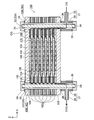
- FIG. 1 is a perspective view showing an external configuration of a fuel cell stack 100 in the present embodiment.
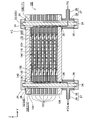
- FIG. 2 is an explanatory diagram showing an XZ cross-sectional configuration of a fuel cell stack 100 at a position II-II in FIG.
- FIG. 3 is an explanatory diagram showing a YZ cross-sectional configuration of a fuel cell stack 100 at a position of III-III in FIG. It is explanatory drawing which shows XZ cross-section structure of the two electric power generation units 102 adjacent to each other in the same position as the cross section shown in FIG. It is explanatory drawing which shows the YZ cross-section structure of the two electric power generation units 102 adjacent to each other in the same position as the cross section shown in FIG. FIG.
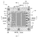
- FIG. 6 is an explanatory diagram showing an XY cross-sectional configuration of a power generation unit 102 at the position VI-VI in FIGS. 4 and 5.
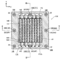
- FIG. 6 is an explanatory diagram showing an XY cross-sectional configuration of a power generation unit 102 at the position VII-VII in FIGS. 4 and 5.
- 4 is a flowchart showing a method for manufacturing the fuel cell stack 100. It is explanatory drawing which shows a performance evaluation result. It is explanatory drawing which shows the result of the XRD analysis of each sample used for performance evaluation. It is explanatory drawing which shows the result of the XRD analysis of each sample used for performance evaluation.
- FIG. 1 is a perspective view showing an external configuration of the fuel cell stack 100 in the present embodiment
- FIG. 2 is an explanatory diagram showing an XZ cross-sectional configuration of the fuel cell stack 100 at a position II-II in FIG.
- FIG. 3 is an explanatory diagram showing a YZ cross-sectional configuration of the fuel cell stack 100 at the position III-III in FIG.
- XYZ axes orthogonal to each other for specifying the direction are shown.
- the positive direction of the Z axis is referred to as the upward direction
- the negative direction of the Z axis is referred to as the downward direction.
- the fuel cell stack 100 is actually different from such an orientation. It may be installed. The same applies to FIG.
- the fuel cell stack 100 includes a plurality (seven in this embodiment) of fuel cell power generation units (hereinafter simply referred to as “power generation units”) 102 and a pair of end plates 104 and 106.
- the seven power generation units 102 are arranged side by side in a predetermined arrangement direction (vertical direction in the present embodiment).
- the pair of end plates 104 and 106 are arranged so as to sandwich an assembly composed of seven power generation units 102 from above and below.
- the arrangement direction (vertical direction) corresponds to the first direction in the claims.
- a plurality of (eight in the present embodiment) holes penetrating in the vertical direction are formed in the peripheral portion around the Z direction of each layer (power generation unit 102, end plates 104, 106) constituting the fuel cell stack 100.
- the holes formed in each layer and corresponding to each other communicate with each other in the vertical direction to form a communication hole 108 extending in the vertical direction from one end plate 104 to the other end plate 106.
- the holes formed in each layer of the fuel cell stack 100 to form the communication holes 108 may also be referred to as communication holes 108.
- the bolts 22 extending in the vertical direction are inserted into the communication holes 108, and the fuel cell stack 100 is fastened by the bolts 22 and the nuts 24 fitted on both sides of the bolts 22. 2 and 3, between the nut 24 fitted on one side (upper side) of the bolt 22 and the upper surface of the end plate 104 constituting the upper end of the fuel cell stack 100, and the bolt An insulating sheet 26 is interposed between the nut 24 fitted on the other side (lower side) of 22 and the lower surface of the end plate 106 constituting the lower end of the fuel cell stack 100.
- an insulating sheet disposed between the nut 24 and the surface of the end plate 106 on the upper and lower sides of the gas passage member 27 and the gas passage member 27, respectively. 26 is interposed.
- the insulating sheet 26 is made of, for example, a mica sheet, a ceramic fiber sheet, a ceramic powder sheet, a glass sheet, a glass ceramic composite agent, or the like.
- the outer diameter of the shaft portion of each bolt 22 is smaller than the inner diameter of each communication hole 108. Therefore, a space is secured between the outer peripheral surface of the shaft portion of each bolt 22 and the inner peripheral surface of each communication hole 108.
- the fuel cell stack 100 is located near the midpoint of one side (the X-axis positive direction side of two sides parallel to the Y-axis) on the outer periphery around the Z-direction.
- the space formed by the bolt 22 (bolt 22A) and the communication hole 108 through which the bolt 22A is inserted is introduced with the oxidant gas OG from the outside of the fuel cell stack 100, and the oxidant gas OG is generated by each power generation.
- oxidant gas introduction manifold 161 that is a gas flow path to be supplied to the unit 102, and is the midpoint of the side opposite to the side (X-axis negative direction side of two sides parallel to the Y-axis)
- the space formed by the bolts 22 (bolts 22B) located in the vicinity and the communication holes 108 through which the bolts 22B are inserted contains the oxidant off-gas OOG that is the gas discharged from the air chamber 166 of each power generation unit 102.
- Burning Functions as the oxidizing gas discharging manifold 162 for discharging to the outside of the cell stack 100. In the present embodiment, for example, air is used as the oxidant gas OG.
- the vicinity of the midpoint of one side (the side on the Y axis positive direction side of two sides parallel to the X axis) on the outer periphery of the fuel cell stack 100 around the Z direction The space formed by the bolt 22 (bolt 22D) positioned at the position and the communication hole 108 through which the bolt 22D is inserted is introduced with the fuel gas FG from the outside of the fuel cell stack 100, and the fuel gas FG is generated by each power generation.
- the space formed by the (bolt 22E) and the communication hole 108 through which the bolt 22E is inserted is a fuel cell stack in which the fuel off-gas FOG that is the gas discharged from the fuel chamber 176 of each power generation unit 102 is supplied to the fuel cell stack. 00 and to the outside to function as a fuel gas discharge manifold 172 for discharging.
- the fuel gas FG for example, hydrogen-rich gas obtained by reforming city gas is used.
- the fuel cell stack 100 is provided with four gas passage members 27.
- Each gas passage member 27 has a hollow cylindrical main body portion 28 and a hollow cylindrical branch portion 29 branched from the side surface of the main body portion 28.
- the hole of the branch part 29 communicates with the hole of the main body part 28.
- a gas pipe (not shown) is connected to the branch portion 29 of each gas passage member 27.
- a forming the oxidant gas introduction manifold 161 communicates with the oxidant gas introduction manifold 161.
- the hole of the main body portion 28 of the gas passage member 27 disposed at the position of the bolt 22 ⁇ / b> B that forms the oxidant gas discharge manifold 162 communicates with the oxidant gas discharge manifold 162. Further, as shown in FIG. 3, the hole of the main body portion 28 of the gas passage member 27 arranged at the position of the bolt 22D forming the fuel gas introduction manifold 171 communicates with the fuel gas introduction manifold 171 and the fuel gas The hole of the main body portion 28 of the gas passage member 27 disposed at the position of the bolt 22 ⁇ / b> E forming the discharge manifold 172 communicates with the fuel gas discharge manifold 172.
- the pair of end plates 104 and 106 are substantially rectangular flat plate-shaped conductive members, and are formed of, for example, stainless steel.
- One end plate 104 is disposed on the upper side of the power generation unit 102 located on the uppermost side, and the other end plate 106 is disposed on the lower side of the power generation unit 102 located on the lowermost side.
- a plurality of power generation units 102 are held in a pressed state by a pair of end plates 104 and 106.
- the upper end plate 104 functions as a positive output terminal of the fuel cell stack 100
- the lower end plate 106 functions as a negative output terminal of the fuel cell stack 100.
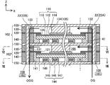
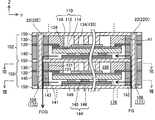
- (Configuration of power generation unit 102) 4 is an explanatory diagram showing an XZ cross-sectional configuration of two power generation units 102 adjacent to each other at the same position as the cross section shown in FIG. 2, and FIG. 5 is adjacent to each other at the same position as the cross section shown in FIG. It is explanatory drawing which shows the YZ cross-section structure of the two electric power generation units.
- 6 is an explanatory diagram showing an XY cross-sectional configuration of the power generation unit 102 at the position VI-VI in FIGS. 4 and 5
- FIG. 7 is a power generation unit at the position VII-VII in FIGS. It is explanatory drawing which shows XY cross-section structure of 102.
- the power generation unit 102 includes a single cell 110, a separator 120, an air electrode side frame 130, an air electrode side current collector 134, a fuel electrode side frame 140, and a fuel electrode side.
- a current collector 144 and a pair of interconnectors 150 constituting the uppermost layer and the lowermost layer of the power generation unit 102 are provided.
- the separator 120, the air electrode side frame 130, the fuel electrode side frame 140, and the periphery of the interconnector 150 around the Z direction are formed with holes corresponding to the communication holes 108 through which the bolts 22 are inserted.
- the interconnector 150 is a substantially rectangular flat plate-shaped conductive member, and is formed of, for example, ferritic stainless steel.
- the interconnector 150 ensures electrical continuity between the power generation units 102 and prevents reaction gas from being mixed between the power generation units 102.
- one interconnector 150 is shared by two adjacent power generation units 102. That is, the upper interconnector 150 in a power generation unit 102 is the same member as the lower interconnector 150 in another power generation unit 102 adjacent to the upper side of the power generation unit 102.
- the power generation unit 102 located at the top in the fuel cell stack 100 does not include the upper interconnector 150 and is located at the bottom.
- the power generation unit 102 does not include the lower interconnector 150 (see FIGS. 2 and 3).
- the single cell 110 includes an electrolyte layer 112 and an air electrode (cathode) 114 and a fuel electrode (anode) 116 that face each other in the vertical direction (the arrangement direction in which the power generation units 102 are arranged) with the electrolyte layer 112 interposed therebetween.
- the single cell 110 of the present embodiment is a fuel electrode-supported single cell that supports the electrolyte layer 112 and the air electrode 114 with the fuel electrode 116.
- the electrolyte layer 112 is a substantially rectangular flat plate member as viewed in the Z direction, and is a dense (low porosity) layer.
- the electrolyte layer 112 is formed of a solid oxide such as YSZ (yttria stabilized zirconia), ScSZ (scandia stabilized zirconia), SDC (samarium doped ceria), GDC (gadolinium doped ceria), perovskite oxide, and the like.
- the air electrode 114 is a substantially rectangular flat plate-shaped member smaller than the electrolyte layer 112 when viewed in the Z direction, and is a porous layer (having a higher porosity than the electrolyte layer 112).
- the air electrode 114 is made of, for example, a perovskite oxide (for example, LSCF (lanthanum strontium cobalt iron oxide), LSM (lanthanum strontium manganese oxide), LNF (lanthanum nickel iron)).
- the fuel electrode 116 is a substantially rectangular flat plate member having substantially the same size as the electrolyte layer 112 as viewed in the Z direction, and is a porous layer (having a higher porosity than the electrolyte layer 112).
- the fuel electrode 116 is made of, for example, Ni (nickel), cermet made of Ni and ceramic particles, Ni-based alloy, or the like.
- the single cell 110 (power generation unit 102) of the present embodiment is a solid oxide fuel cell (SOFC) that uses a solid oxide as an electrolyte.
- SOFC solid oxide fuel cell
- the separator 120 is a frame-like member in which a substantially rectangular hole 121 penetrating in the vertical direction is formed near the center, and is made of, for example, metal.
- the peripheral part of the hole 121 in the separator 120 is opposed to the peripheral part of the surface of the electrolyte layer 112 on the air electrode 114 side.
- the separator 120 is bonded to the electrolyte layer 112 (single cell 110) by a bonding portion 124 formed of a brazing material (for example, Ag brazing) disposed in the facing portion.
- the separator 120 divides the air chamber 166 facing the air electrode 114 and the fuel chamber 176 facing the fuel electrode 116, and gas leaks from one electrode side to the other electrode side in the peripheral portion of the single cell 110. It is suppressed.
- the air electrode side frame 130 is a frame-like member in which a substantially rectangular hole 131 penetrating in the vertical direction is formed near the center, and is formed of an insulator such as mica, for example. .
- the hole 131 of the air electrode side frame 130 forms an air chamber 166 that faces the air electrode 114.
- the air electrode side frame 130 is in contact with the peripheral edge portion of the surface of the separator 120 opposite to the side facing the electrolyte layer 112 and the peripheral edge portion of the surface of the interconnector 150 facing the air electrode 114.
- the pair of interconnectors 150 included in the power generation unit 102 is electrically insulated by the air electrode side frame 130.
- the air electrode side frame 130 has an oxidant gas supply passage 132 communicating the oxidant gas introduction manifold 161 and the air chamber 166, and an oxidant gas communicating the air chamber 166 and the oxidant gas discharge manifold 162.
- a discharge communication hole 133 is formed.
- the fuel electrode side frame 140 is a frame-like member in which a substantially rectangular hole 141 penetrating in the vertical direction is formed near the center, and is made of, for example, metal.
- the hole 141 of the fuel electrode side frame 140 forms a fuel chamber 176 that faces the fuel electrode 116.
- the fuel electrode side frame 140 is in contact with the peripheral portion of the surface of the separator 120 facing the electrolyte layer 112 and the peripheral portion of the surface of the interconnector 150 facing the fuel electrode 116.
- the fuel electrode side frame 140 has a fuel gas supply communication hole 142 that connects the fuel gas introduction manifold 171 and the fuel chamber 176, and a fuel gas discharge communication hole 143 that connects the fuel chamber 176 and the fuel gas discharge manifold 172. And are formed.
- the air electrode side current collector 134 is disposed in the air chamber 166.
- the air electrode side current collector 134 is composed of a plurality of current collector elements 135 having a substantially quadrangular prism shape, and is formed of, for example, ferritic stainless steel.
- the air electrode side current collector 134 is in contact with the surface of the air electrode 114 opposite to the side facing the electrolyte layer 112 and the surface of the interconnector 150 facing the air electrode 114.
- the air electrode side current collector 134 in the power generation unit 102 includes the upper end plate. 104 is in contact.
- the air electrode side current collector 134 has such a configuration, the air electrode 114 and the interconnector 150 (or the end plate 104) are electrically connected.
- the air electrode side current collector 134 and the interconnector 150 are formed as an integral member. That is, a flat plate portion perpendicular to the vertical direction (Z-axis direction) of the integrated member functions as the interconnector 150 and is formed so as to protrude from the flat plate portion toward the air electrode 114.
- the current collector element 135 that is a plurality of convex portions functions as the air electrode side current collector 134.
- the integral member of the air electrode side current collector 134 and the interconnector 150 may be covered with a conductive coat, and between the air electrode 114 and the air electrode side current collector 134, A conductive bonding layer to be bonded may be interposed.
- the fuel electrode side current collector 144 is disposed in the fuel chamber 176.
- the fuel electrode side current collector 144 includes an interconnector facing portion 146, an electrode facing portion 145, and a connecting portion 147 that connects the electrode facing portion 145 and the interconnector facing portion 146.
- the electrode facing portion 145 is in contact with the surface of the fuel electrode 116 on the side opposite to the side facing the electrolyte layer 112, and the interconnector facing portion 146 is on the surface of the interconnector 150 on the side facing the fuel electrode 116. In contact.
- the interconnector facing portion 146 in the power generation unit 102 has a lower end plate. 106 is in contact. Since the fuel electrode side current collector 144 has such a configuration, the fuel electrode 116 and the interconnector 150 (or the end plate 106) are electrically connected. Note that a spacer 149 made of, for example, mica is disposed between the electrode facing portion 145 and the interconnector facing portion 146.
- the fuel electrode side current collector 144 follows the deformation of the power generation unit 102 due to the temperature cycle and the reaction gas pressure fluctuation, and the fuel electrode 116 and the interconnector 150 (or the end plate 106) via the fuel electrode side current collector 144.
- the electrical connection with is maintained well.
- the power generation unit 102 of the present embodiment further includes a felt member 41.
- the felt member 41 is positioned at both ends (Z-axis direction) in a direction (Y-axis direction) orthogonal to the main flow direction (X-axis direction) of the oxidant gas OG.
- the felt member 41 is disposed between the outer surface of the air electrode side current collector 134 and the surface of the hole 131 of the air electrode side frame 130 in the direction orthogonal to the Z axis direction (Y axis direction). .
- FIGS. 4 and 6 in the air chamber 166, the felt member 41 is positioned at both ends (Z-axis direction) in a direction (Y-axis direction) orthogonal to the main flow direction (X-axis direction) of the oxidant gas OG.
- the felt member 41 is disposed between the outer surface of the air electrode side current collector 134 and the surface of the hole 131 of the air electrode side frame 130 in the direction orthogonal to the Z axis direction (Y axis direction
- the felt member 41 has positions (Z-axis) at both ends in the direction (X-axis direction) orthogonal to the main flow direction (Y-axis direction) of the fuel gas FG in the fuel chamber 176. It is also filled in a position (a position not overlapping with the air electrode 114 of the single cell 110 in the direction). That is, the felt member 41 is disposed between the outer surface of the fuel electrode side current collector 144 and the surface of the hole 141 of the fuel electrode side frame 140 in the direction orthogonal to the Z axis direction (X axis direction). .
- the oxidant gas OG supplied to the air chamber 166 or the fuel gas FG supplied to the fuel chamber 176 passes through a region that does not contribute much to power generation and is discharged from the air chamber 166 or the fuel chamber 176. It can be suppressed and power generation efficiency can be improved.
- the air electrode 114 and the fuel electrode 116 in the present embodiment correspond to specific electrodes in the claims.
- the air electrode side frame 130 and the fuel electrode side frame 140 in the present embodiment correspond to frame members in the claims, and the air electrode side current collector 134 and the fuel electrode side current collector 144 in the present embodiment are This corresponds to the current collecting member in the claims.
- the felt member 41 is made of an alumina-silica (silicon dioxide) felt material. That is, the felt member 41 contains alumina which is ceramic and a silica component. When the felt member 41 contains alumina, the heat resistance and flexibility of the felt member 41 can be improved.
- the felt member 41 used in the present embodiment has an Al 2 O 3 crystal structure and also has an SiO 2 crystal structure. The crystal structure of Al 2 O 3 corresponds to the first crystal structure in the claims, and the crystal structure of SiO 2 corresponds to the second crystal structure in the claims.
- the oxidant gas is connected via a gas pipe (not shown) connected to the branch portion 29 of the gas passage member 27 provided at the position of the oxidant gas introduction manifold 161.
- a gas pipe (not shown) connected to the branch portion 29 of the gas passage member 27 provided at the position of the oxidant gas introduction manifold 161.
- the oxidant gas OG is supplied to the oxidant gas introduction manifold 161 through the branch part 29 of the gas passage member 27 and the hole of the main body part 28, and each power generation unit is supplied from the oxidant gas introduction manifold 161.
- 102 is supplied to the air chamber 166 through the oxidant gas supply communication hole 132. Further, as shown in FIGS.
- the fuel gas is supplied via a gas pipe (not shown) connected to the branch portion 29 of the gas passage member 27 provided at the position of the fuel gas introduction manifold 171.
- a gas pipe (not shown) connected to the branch portion 29 of the gas passage member 27 provided at the position of the fuel gas introduction manifold 171.
- the fuel gas FG is supplied to the fuel gas introduction manifold 171 through the branch portion 29 of the gas passage member 27 and the hole of the main body portion 28, and the fuel of each power generation unit 102 is supplied from the fuel gas introduction manifold 171.
- the fuel is supplied to the fuel chamber 176 through the gas supply communication hole 142.
- each power generation unit 102 When the oxidant gas OG is supplied to the air chamber 166 of each power generation unit 102 and the fuel gas FG is supplied to the fuel chamber 176, oxygen contained in the oxidant gas OG and hydrogen contained in the fuel gas FG in the single cell 110. Power is generated by an electrochemical reaction. This power generation reaction is an exothermic reaction.
- the air electrode 114 of the single cell 110 is electrically connected to one interconnector 150 via the air electrode side current collector 134, and the fuel electrode 116 is connected via the fuel electrode side current collector 144.
- the other interconnector 150 is electrically connected.
- the plurality of power generation units 102 included in the fuel cell stack 100 are electrically connected in series.
- each power generation unit 102 electrical energy generated in each power generation unit 102 is taken out from the end plates 104 and 106 that function as output terminals of the fuel cell stack 100. Since SOFC generates power at a relatively high temperature (for example, 700 ° C. to 1000 ° C.), the fuel cell stack 100 is heated by a heater (after the start-up until the high temperature can be maintained by the heat generated by the power generation. (Not shown).
- the oxidant off-gas OOG discharged from the air chamber 166 of each power generation unit 102 is discharged to the oxidant gas discharge manifold 162 through the oxidant gas discharge communication hole 133 as shown in FIGS. Further, the fuel passes through the holes of the main body portion 28 and the branch portion 29 of the gas passage member 27 provided at the position of the oxidant gas discharge manifold 162 and is connected to the branch portion 29 through a gas pipe (not shown). It is discharged outside the battery stack 100. Further, the fuel off-gas FOG discharged from the fuel chamber 176 of each power generation unit 102 is discharged to the fuel gas discharge manifold 172 via the fuel gas discharge communication hole 143 as shown in FIGS. 3, 5, and 7.
- the fuel cell stack 100 is connected to a gas pipe member (not shown) connected to the branch portion 29 through the holes of the main body portion 28 and the branch portion 29 of the gas passage member 27 provided at the position of the fuel gas discharge manifold 172. Is discharged outside.
- FIG. 8 is a flowchart showing a method for manufacturing the fuel cell stack 100.
- a felt raw material is prepared (S110).
- As the felt raw material a commercially available alumina-silica felt raw material having a crystal structure of Al 2 O 3 is used.
- the alumina-silica felt raw material contains alumina and amorphous silica as a silica component.
- the felt raw material 41 is fabricated by heat-treating the felt raw material at 1000 ° C. or higher and then forming it (S120).
- the temperature of heat processing can be 1300 degrees C or less, for example.
- the heat treatment time can be, for example, 8 to 12 hours.
- the power generation unit 102 is produced by a known method (S130). At this time, as described above, the felt member 41 produced in S120 is filled in predetermined positions of the air chamber 166 and the fuel chamber 176.
- a plurality of the generated power generation units 102 are arranged in a predetermined arrangement direction (vertical direction), and each member is assembled to manufacture the fuel cell stack 100 (S140). With the above steps, the manufacture of the fuel cell stack 100 having the above-described configuration is completed.
- FIG. 9 is an explanatory diagram showing the performance evaluation results.
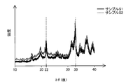
- 10 and 11 are explanatory diagrams showing the results of XRD analysis (X-Ray Diffraction Analysis) of each sample used for performance evaluation.
- samples S1 to S4 are materials having a crystal structure of Al 2 O 3 .
- samples S3 and S4 are materials that do not have an Al 2 O 3 crystal structure.
- FIG. 10 shows the XRD analysis results for samples S2 and S4 on behalf of each sample. For sample S2, a peak near 33 degrees derived from the crystal structure of Al 2 O 3 was observed, whereas for sample S4, such a peak was not observed. Although not shown, for sample S1, a peak derived from the crystal structure of Al 2 O 3 is observed as in sample S2, and for sample S3, such a peak is observed as in sample S4. There wasn't.
- samples S1 and S3 are heat-treated at 1000 ° C. (10 hours). On the other hand, such heat treatment is not performed on samples S2 and S4.
- samples S1 and S3 have a SiO 2 crystal structure
- samples S2 and S4 do not have a SiO 2 crystal structure.
- FIG. 11 shows the XRD analysis results for samples S1 and S2 on behalf of each sample.
- sample S1 For sample S1, a peak at around 22 degrees derived from the crystal structure of SiO 2 was observed, whereas for sample S2, such a peak was not observed. Although not shown, for sample S3, a peak derived from the crystal structure of SiO 2 was observed as in sample S1, and for sample S4, such a peak was not observed as in sample S2. .
- the ratio of the intensity of the peak derived from the crystal structure of SiO 2 to the intensity of the peak derived from the crystal structure of Al 2 O 3 in XRD analysis was calculated.
- the intensity was assumed to be zero.
- the crystal peak intensity ratio was 0.61.
- the peak derived from the crystal structure of SiO 2 does not exist, so the crystal peak intensity ratio was zero.
- sample S3 since the peak derived from the crystal structure of Al 2 O 3 does not exist, the crystal peak intensity ratio was infinite. Thus, it was confirmed that the felt material of sample S1 contained crystalline silica by heat treatment.
- Si scattering test evaluation was performed on two items, a Si scattering test and a durability characteristic test.
- Si scattering test for each sample, the sample and the single cell 110 are placed in a crucible at a predetermined interval, heat-treated at 850 ° C. for 100 hours in a hydrogen atmosphere with a humidity of 40%, and then subjected to XRF analysis.
- the amount of Si (ppm) on the surface of the single cell 110 was quantified by (X-Ray Fluorescence Analysis). When the amount of Si was less than 100 ppm, it was determined to be acceptable ( ⁇ ), and when the amount of Si was 100 ppm or more, it was determined to be unacceptable (x).
- the fuel cell stack 100 including the felt member 41 made of the sample felt material is subjected to a rated power generation operation at 850 ° C. for 100 hours, and then the temperature 700
- the voltage at 0 ° C. and a current density of 0.55 A / cm 2 was measured, and the increase in ⁇ resistance ( ⁇ ( ⁇ )) was calculated from the difference from the initial voltage.
- ⁇ was less than 0.1 ⁇ , it was judged as acceptable ( ⁇ ), and when ⁇ was 0.1 ⁇ or more, it was judged as unacceptable (x).
- the Si poisoning amount (ppm) of the portion on the electrolyte layer 112 side (portion where the electrode is active) in the fuel electrode 116 was determined by D-SIMS analysis (Dynamic-Secondary Ion Mass Spectrometry Analysis). .
- the felt material of sample S3 has the crystal structure of SiO 2 like sample S1, it does not have the crystal structure of Al 2 O 3 , and thus cannot suppress the scattering of Si. It was. Even if the felt material has the crystal structure of SiO 2 , the shape of the felt material cannot be maintained unless the crystal structure of Al 2 O 3 is used, and the heat resistance is also good. Since it is inferior, it is thought that it is because the felt material which became granular during the test scattered. Moreover, since the felt material of sample S4 has neither the crystal structure of Al 2 O 3 nor the crystal structure of SiO 2 , it is considered that the scattering of Si could not be suppressed.
- the felt member 41 is formed using a felt material having an Al 2 O 3 crystal structure and an SiO 2 crystal structure, the Si scattering from the felt member 41 is achieved. It was confirmed that it can be suppressed.
- sample S1 in the durability characteristic test, in sample S1, ⁇ was less than 0.1 ⁇ (0.06 ⁇ ), so it was determined to be acceptable ( ⁇ ). Since the Fe material of sample S1 has a small amount of Si in the Si scattering test, poisoning of the single cell 110 by Si as a contaminant is suppressed, and ⁇ resistance (activation polarization within ⁇ resistance) increases. It is thought that it was suppressed. In sample S1, the Si poisoning amount of the fuel electrode 116 was as small as 200 ppm. On the other hand, in sample S4, since ⁇ was 0.1 ⁇ or more (0.12 ⁇ ), it was determined as rejected (x).
- sample S4 Since the felt material of sample S4 has a large amount of Si in the Si scattering test, it is considered that the single cell 110 was poisoned by Si as a contaminant and the ⁇ resistance increased. In sample S4, the Si poisoning amount of the fuel electrode 116 was as high as 850 ppm. With respect to sample S2, the shape could not be maintained and the assembly could not be performed, so the durability characteristic test could not be performed. In addition, for the sample S3, since the felt material contracted by the heat treatment, the durability characteristic test could not be performed.
- the felt member 41 includes ceramics (alumina) and a silica component, has a crystal structure of Al 2 O 3 , and has a crystal structure of SiO 2. Then, it is confirmed that the scattering of contaminants such as Si from the felt member 41 can be suppressed, and the occurrence of deterioration in the performance of the unit cell 110 due to poisoning by contaminants such as Si can be suppressed. It was done. In order to suppress scattering of contaminants such as Si, it is preferable to reduce the Si content in the felt material. However, a felt material having a low Si content has poor handling properties, and may cause problems such as cracking or shattering during assembly.
- the configuration of the fuel cell stack 100 in the above embodiment is merely an example, and various modifications can be made.
- the filling position of the felt member 41 in the above embodiment is merely an example, and the felt member 41 may be filled in other positions of the fuel cell stack 100.
- the felt member 41 is made of an alumina-silica felt material, but may be made of another ceramic-silica felt material other than alumina. Alternatively, the felt member 41 may be made of a metal-silica felt material (for example, nickel felt). Also in such a configuration, the felt member 41 includes a ceramic or metal and a silica component, and has a crystal structure (first crystal structure) corresponding to the ceramic or metal contained therein, and SiO 2. If the crystal structure (second crystal structure) is provided, the scattering of contaminants such as Si from the felt member 41 can be suppressed, and a single cell caused by poisoning due to contaminants such as Si The occurrence of 110 performance degradation can be suppressed.
- the fact that the member B and the member C face each other across the member A (or a part where the member is present, the same applies hereinafter) A is limited to a form in which the member A and the member B or the member C are adjacent to each other. It includes a form in which other components are interposed between the member A and the member B or the member C.
- another layer may be provided between the electrolyte layer 112 and the air electrode 114. Even with such a configuration, it can be said that the air electrode 114 and the fuel electrode 116 face each other with the electrolyte layer 112 interposed therebetween.
- the fuel cell stack 100 is the structure by which the several flat plate-shaped electric power generation unit 102 was laminated
- this invention is described in other structures, for example, international publication 2012/165409.
- the present invention can be similarly applied to a configuration in which a plurality of substantially cylindrical fuel cell single cells are connected in series.
- the SOFC that generates electricity using the electrochemical reaction between hydrogen contained in the fuel gas and oxygen contained in the oxidant gas is targeted.
- the present invention can be similarly applied to an electrolytic cell unit that is a constituent unit of a solid oxide electrolytic cell (SOEC) that generates hydrogen by using hydrogen, and an electrolytic cell stack including a plurality of electrolytic cell units.
- SOEC solid oxide electrolytic cell
- the configuration of the electrolytic cell stack is well known as described in, for example, Japanese Patent Application Laid-Open No. 2016-81813, and thus will not be described in detail here. However, it is schematically the same as the fuel cell stack 100 in the above-described embodiment. It is the composition.
- the fuel cell stack 100 in the above-described embodiment may be read as an electrolytic cell stack
- the power generation unit 102 may be read as an electrolytic cell unit
- the single cell 110 may be read as an electrolytic single cell.
- a voltage is applied between the two electrodes so that the air electrode 114 is positive (anode) and the fuel electrode 116 is negative (cathode).
- Water vapor as a source gas is supplied.
- an electrolysis reaction of water occurs in each electrolysis cell unit, hydrogen gas is generated in the fuel chamber 176, and hydrogen is taken out of the electrolysis cell stack through the communication hole.
- the solid oxide fuel cell has been described as an example.
- the present invention is applicable to other types of fuel cells (or electrolytic cells) such as a molten carbonate fuel cell (MCFC). Applicable.
- Fuel cell stack 102 Fuel cell power generation unit 104: End plate 106: End plate 108: Communication hole 110: Single cell 112: Electrolyte layer 114: Air electrode 116: Fuel electrode 120: Separator 121: Hole 124: Joint part 130: Air electrode side frame 131: Hole 132: Oxidant gas supply communication hole 133: Oxidant gas discharge communication Hole 134: Air electrode side current collector 135: Current collector element 140: Fuel electrode side frame 141: Hole 142: Fuel gas supply communication hole 143: Fuel gas discharge communication hole 144: Fuel electrode side current collector 145: Electrode facing Part 146: Interconnector facing part 147: Ream Part 149: spacer 150: interconnector 161: oxidizing gas inlet manifold 162: oxidizing gas discharging manifold 166: an air chamber 171: fuel gas inlet manifold 172: fuel
Landscapes
- Chemical & Material Sciences (AREA)
- Engineering & Computer Science (AREA)
- Electrochemistry (AREA)
- Chemical Kinetics & Catalysis (AREA)
- Sustainable Development (AREA)
- Sustainable Energy (AREA)
- Life Sciences & Earth Sciences (AREA)
- Manufacturing & Machinery (AREA)
- General Chemical & Material Sciences (AREA)
- Materials Engineering (AREA)
- Metallurgy (AREA)
- Organic Chemistry (AREA)
- Inorganic Chemistry (AREA)
- Fuel Cell (AREA)
Abstract
Priority Applications (6)
| Application Number | Priority Date | Filing Date | Title |
|---|---|---|---|
| EP18757019.7A EP3588643B1 (fr) | 2017-02-27 | 2018-01-31 | Unité de réaction électrochimique, empilement de cellules de réaction électrochimique, et procédé de production pour unité de réaction électrochimique |
| KR1020197024925A KR102254281B1 (ko) | 2017-02-27 | 2018-01-31 | 전기 화학 반응 단위, 전기 화학 반응 셀 스택, 및, 전기 화학 반응 단위의 제조 방법 |
| DK18757019.7T DK3588643T3 (da) | 2017-02-27 | 2018-01-31 | ELEKTROKEMISK REAKTIONSENHED, ELEKTROKEMISK REAKTIONSCELLESTAK OG FREMSTILLINGSFREMGANGSMåDE TIL ELEKTROKEMISK REAKTIONSENHED |
| CN201880014234.8A CN110337747B (zh) | 2017-02-27 | 2018-01-31 | 电化学反应单位、电化学反应电池组、以及电化学反应单位的制造方法 |
| JP2018517910A JP6573719B2 (ja) | 2017-02-27 | 2018-01-31 | 電気化学反応単位、電気化学反応セルスタック、および、電気化学反応単位の製造方法 |
| US16/488,819 US11289727B2 (en) | 2017-02-27 | 2018-01-31 | Electrochemical reaction unit, electrochemical reaction cell stack, and production method for electrochemical reaction unit |
Applications Claiming Priority (2)
| Application Number | Priority Date | Filing Date | Title |
|---|---|---|---|
| JP2017034322 | 2017-02-27 | ||
| JP2017-034322 | 2017-02-27 |
Publications (1)
| Publication Number | Publication Date |
|---|---|
| WO2018155111A1 true WO2018155111A1 (fr) | 2018-08-30 |
Family
ID=63253666
Family Applications (1)
| Application Number | Title | Priority Date | Filing Date |
|---|---|---|---|
| PCT/JP2018/003129 Ceased WO2018155111A1 (fr) | 2017-02-27 | 2018-01-31 | Unité de réaction électrochimique, empilement de cellules de réaction électrochimique, et procédé de production pour unité de réaction électrochimique |
Country Status (7)
| Country | Link |
|---|---|
| US (1) | US11289727B2 (fr) |
| EP (1) | EP3588643B1 (fr) |
| JP (1) | JP6573719B2 (fr) |
| KR (1) | KR102254281B1 (fr) |
| CN (1) | CN110337747B (fr) |
| DK (1) | DK3588643T3 (fr) |
| WO (1) | WO2018155111A1 (fr) |
Citations (9)
| Publication number | Priority date | Publication date | Assignee | Title |
|---|---|---|---|---|
| JPH02242564A (ja) * | 1989-03-15 | 1990-09-26 | Sanyo Electric Co Ltd | 固体電解質燃料電池 |
| JPH05101836A (ja) * | 1991-10-09 | 1993-04-23 | Osaka Gas Co Ltd | 固体電解質型燃料電池 |
| JPH05166529A (ja) | 1991-12-12 | 1993-07-02 | Ngk Insulators Ltd | 発電装置 |
| JPH0636783A (ja) * | 1992-07-17 | 1994-02-10 | Mitsubishi Heavy Ind Ltd | 平板型固体電解質燃料電池用燃料極集電材 |
| JPH06223849A (ja) * | 1993-01-28 | 1994-08-12 | Mitsui Eng & Shipbuild Co Ltd | 固体電解質型燃料電池スタックの接合材およびその製造方法 |
| JP2007141765A (ja) * | 2005-11-22 | 2007-06-07 | Hitachi Ltd | 固体酸化物形燃料電池及びその製作方法 |
| JP2009043550A (ja) * | 2007-08-08 | 2009-02-26 | Ngk Spark Plug Co Ltd | 固体電解質型燃料電池 |
| WO2012165409A1 (fr) | 2011-05-30 | 2012-12-06 | 京セラ株式会社 | Pile à combustible à oxyde solide, système d'empilement de piles à combustibles, module de piles à combustibles et système de piles à combustible |
| JP2016081813A (ja) | 2014-10-20 | 2016-05-16 | 株式会社東芝 | 電気化学セルスタック、および電力システム |
Family Cites Families (15)
| Publication number | Priority date | Publication date | Assignee | Title |
|---|---|---|---|---|
| US4791035A (en) * | 1987-12-10 | 1988-12-13 | Westinghouse Electric Corp. | Cell and current collector felt arrangement for solid oxide electrochemical cell combinations |
| US5292599A (en) | 1991-09-27 | 1994-03-08 | Ngk Insulators, Ltd. | Cell units for solid oxide fuel cells and power generators using such cell units |
| US5856035A (en) * | 1996-02-29 | 1999-01-05 | Gas Research Institute | Electrical connector apparatus for planar solid oxide fuel cell stacks |
| JP5437546B2 (ja) | 2000-08-18 | 2014-03-12 | ヴァーサ パワー システムズ リミテッド | 高温ガスシール |
| JP2005166455A (ja) | 2003-12-03 | 2005-06-23 | Nissan Motor Co Ltd | 固体酸化物形燃料電池用セル、セル板及びその製造方法 |
| US7485386B2 (en) * | 2004-05-27 | 2009-02-03 | Siemens Energy, Inc. | Flexible ceramic gasket for SOFC generator |
| US20070281194A1 (en) * | 2006-05-31 | 2007-12-06 | Jeffrey Earl Cortright | Portable fuel cell assembly |
| JP5274607B2 (ja) * | 2011-03-14 | 2013-08-28 | イビデン株式会社 | 触媒コンバータ用保持シール材及び触媒コンバータ |
| JP5330577B2 (ja) * | 2011-08-09 | 2013-10-30 | 日本特殊陶業株式会社 | 燃料電池セル及び燃料電池スタック |
| EP2953196B1 (fr) * | 2013-01-31 | 2018-07-11 | NGK Sparkplug Co., Ltd. | Pile à combustible et empilement de piles à combustible |
| CA2899561C (fr) * | 2013-01-31 | 2017-10-24 | Ngk Spark Plug Co., Ltd. | Pile a combustible et empilement de piles a combustible a connexion electrique maintenue |
| CA2900459C (fr) * | 2013-02-07 | 2018-07-10 | Morimura Sofc Technology Co., Ltd. | Pile a combustible assurant une distribution uniforme de pression de carburant gazeux dans une generation de production d'energie |
| JP6141753B2 (ja) * | 2013-11-06 | 2017-06-07 | 日本特殊陶業株式会社 | 固体酸化物形燃料電池 |
| EP3096381B1 (fr) * | 2014-01-15 | 2018-10-24 | NGK Spark Plug Co., Ltd. | Cassette de piles à combustible et assemblage de piles à combustible |
| JP6317222B2 (ja) * | 2014-09-22 | 2018-04-25 | 日本特殊陶業株式会社 | 固体酸化物形燃料電池スタック |
-
2018
- 2018-01-31 KR KR1020197024925A patent/KR102254281B1/ko active Active
- 2018-01-31 DK DK18757019.7T patent/DK3588643T3/da active
- 2018-01-31 JP JP2018517910A patent/JP6573719B2/ja active Active
- 2018-01-31 WO PCT/JP2018/003129 patent/WO2018155111A1/fr not_active Ceased
- 2018-01-31 EP EP18757019.7A patent/EP3588643B1/fr active Active
- 2018-01-31 CN CN201880014234.8A patent/CN110337747B/zh active Active
- 2018-01-31 US US16/488,819 patent/US11289727B2/en active Active
Patent Citations (9)
| Publication number | Priority date | Publication date | Assignee | Title |
|---|---|---|---|---|
| JPH02242564A (ja) * | 1989-03-15 | 1990-09-26 | Sanyo Electric Co Ltd | 固体電解質燃料電池 |
| JPH05101836A (ja) * | 1991-10-09 | 1993-04-23 | Osaka Gas Co Ltd | 固体電解質型燃料電池 |
| JPH05166529A (ja) | 1991-12-12 | 1993-07-02 | Ngk Insulators Ltd | 発電装置 |
| JPH0636783A (ja) * | 1992-07-17 | 1994-02-10 | Mitsubishi Heavy Ind Ltd | 平板型固体電解質燃料電池用燃料極集電材 |
| JPH06223849A (ja) * | 1993-01-28 | 1994-08-12 | Mitsui Eng & Shipbuild Co Ltd | 固体電解質型燃料電池スタックの接合材およびその製造方法 |
| JP2007141765A (ja) * | 2005-11-22 | 2007-06-07 | Hitachi Ltd | 固体酸化物形燃料電池及びその製作方法 |
| JP2009043550A (ja) * | 2007-08-08 | 2009-02-26 | Ngk Spark Plug Co Ltd | 固体電解質型燃料電池 |
| WO2012165409A1 (fr) | 2011-05-30 | 2012-12-06 | 京セラ株式会社 | Pile à combustible à oxyde solide, système d'empilement de piles à combustibles, module de piles à combustibles et système de piles à combustible |
| JP2016081813A (ja) | 2014-10-20 | 2016-05-16 | 株式会社東芝 | 電気化学セルスタック、および電力システム |
Non-Patent Citations (1)
| Title |
|---|
| See also references of EP3588643A4 |
Also Published As
| Publication number | Publication date |
|---|---|
| JP6573719B2 (ja) | 2019-09-11 |
| JPWO2018155111A1 (ja) | 2019-02-28 |
| EP3588643A4 (fr) | 2021-01-13 |
| US11289727B2 (en) | 2022-03-29 |
| CN110337747A (zh) | 2019-10-15 |
| KR102254281B1 (ko) | 2021-05-21 |
| EP3588643B1 (fr) | 2024-07-03 |
| EP3588643A1 (fr) | 2020-01-01 |
| CN110337747B (zh) | 2022-08-02 |
| US20210135262A1 (en) | 2021-05-06 |
| DK3588643T3 (da) | 2024-07-22 |
| KR20190111092A (ko) | 2019-10-01 |
Similar Documents
| Publication | Publication Date | Title |
|---|---|---|
| JP6573720B2 (ja) | 電気化学反応単位および電気化学反応セルスタック | |
| JP7079220B2 (ja) | 電気化学反応セルスタック | |
| JP6734723B2 (ja) | 電気化学反応単セル、および、電気化学反応セルスタック | |
| JP6560621B2 (ja) | 電気化学反応単セル、インターコネクタ−電気化学反応単セル複合体、および、電気化学反応セルスタック | |
| JP6797150B2 (ja) | 電気化学反応単位、電気化学反応セルスタック、および、電気化学反応単位の製造方法 | |
| JP6573719B2 (ja) | 電気化学反応単位、電気化学反応セルスタック、および、電気化学反応単位の製造方法 | |
| JP7061105B2 (ja) | 電気化学反応単セルおよび電気化学反応セルスタック | |
| JP2018014309A (ja) | 電気化学反応セルスタックの製造方法および電気化学反応セルスタック | |
| CN108701839B (zh) | 电化学反应单体电池和电化学反应电池堆 | |
| JP7096642B2 (ja) | 電気化学反応単位および電気化学反応セルスタック | |
| JP6780920B2 (ja) | 燃料電池単セルおよび燃料電池スタック | |
| JP6951383B2 (ja) | 電気化学反応セルスタック | |
| JP6609710B2 (ja) | マイカ製部材、電気化学反応単位、および、電気化学反応セルスタック | |
| JP7096643B2 (ja) | 電気化学反応単位および電気化学反応セルスタック | |
| JP7096644B2 (ja) | 電気化学反応単位および電気化学反応セルスタック |
Legal Events
| Date | Code | Title | Description |
|---|---|---|---|
| ENP | Entry into the national phase |
Ref document number: 2018517910 Country of ref document: JP Kind code of ref document: A |
|
| 121 | Ep: the epo has been informed by wipo that ep was designated in this application |
Ref document number: 18757019 Country of ref document: EP Kind code of ref document: A1 |
|
| ENP | Entry into the national phase |
Ref document number: 20197024925 Country of ref document: KR Kind code of ref document: A |
|
| NENP | Non-entry into the national phase |
Ref country code: DE |
|
| WWE | Wipo information: entry into national phase |
Ref document number: 2018757019 Country of ref document: EP |