EP3588732B1 - Appareil de traitement du sol doté d'un appareil de base et d'un appareil accessoire raccordable de manière amovible à l'appareil de base - Google Patents
Appareil de traitement du sol doté d'un appareil de base et d'un appareil accessoire raccordable de manière amovible à l'appareil de base Download PDFInfo
- Publication number
- EP3588732B1 EP3588732B1 EP19180752.8A EP19180752A EP3588732B1 EP 3588732 B1 EP3588732 B1 EP 3588732B1 EP 19180752 A EP19180752 A EP 19180752A EP 3588732 B1 EP3588732 B1 EP 3588732B1
- Authority
- EP
- European Patent Office
- Prior art keywords
- consumer
- power consumption
- floor treatment
- treatment device
- floor
- Prior art date
- Legal status (The legal status is an assumption and is not a legal conclusion. Google has not performed a legal analysis and makes no representation as to the accuracy of the status listed.)
- Active
Links
Images


Classifications
-
- A—HUMAN NECESSITIES
- A47—FURNITURE; DOMESTIC ARTICLES OR APPLIANCES; COFFEE MILLS; SPICE MILLS; SUCTION CLEANERS IN GENERAL
- A47L—DOMESTIC WASHING OR CLEANING; SUCTION CLEANERS IN GENERAL
- A47L5/00—Structural features of suction cleaners
- A47L5/12—Structural features of suction cleaners with power-driven air-pumps or air-compressors, e.g. driven by motor vehicle engine vacuum
- A47L5/22—Structural features of suction cleaners with power-driven air-pumps or air-compressors, e.g. driven by motor vehicle engine vacuum with rotary fans
- A47L5/28—Suction cleaners with handles and nozzles fixed on the casings, e.g. wheeled suction cleaners with steering handle
- A47L5/30—Suction cleaners with handles and nozzles fixed on the casings, e.g. wheeled suction cleaners with steering handle with driven dust-loosening tools, e.g. rotating brushes
-
- A—HUMAN NECESSITIES
- A47—FURNITURE; DOMESTIC ARTICLES OR APPLIANCES; COFFEE MILLS; SPICE MILLS; SUCTION CLEANERS IN GENERAL
- A47L—DOMESTIC WASHING OR CLEANING; SUCTION CLEANERS IN GENERAL
- A47L5/00—Structural features of suction cleaners
- A47L5/12—Structural features of suction cleaners with power-driven air-pumps or air-compressors, e.g. driven by motor vehicle engine vacuum
- A47L5/22—Structural features of suction cleaners with power-driven air-pumps or air-compressors, e.g. driven by motor vehicle engine vacuum with rotary fans
- A47L5/24—Hand-supported suction cleaners
-
- A—HUMAN NECESSITIES
- A47—FURNITURE; DOMESTIC ARTICLES OR APPLIANCES; COFFEE MILLS; SPICE MILLS; SUCTION CLEANERS IN GENERAL
- A47L—DOMESTIC WASHING OR CLEANING; SUCTION CLEANERS IN GENERAL
- A47L9/00—Details or accessories of suction cleaners, e.g. mechanical means for controlling the suction or for effecting pulsating action; Storing devices specially adapted to suction cleaners or parts thereof; Carrying-vehicles specially adapted for suction cleaners
- A47L9/02—Nozzles
- A47L9/04—Nozzles with driven brushes or agitators
- A47L9/0405—Driving means for the brushes or agitators
- A47L9/0411—Driving means for the brushes or agitators driven by electric motor
-
- A—HUMAN NECESSITIES
- A47—FURNITURE; DOMESTIC ARTICLES OR APPLIANCES; COFFEE MILLS; SPICE MILLS; SUCTION CLEANERS IN GENERAL
- A47L—DOMESTIC WASHING OR CLEANING; SUCTION CLEANERS IN GENERAL
- A47L9/00—Details or accessories of suction cleaners, e.g. mechanical means for controlling the suction or for effecting pulsating action; Storing devices specially adapted to suction cleaners or parts thereof; Carrying-vehicles specially adapted for suction cleaners
- A47L9/02—Nozzles
- A47L9/04—Nozzles with driven brushes or agitators
- A47L9/0461—Dust-loosening tools, e.g. agitators, brushes
- A47L9/0466—Rotating tools
- A47L9/0477—Rolls
-
- A—HUMAN NECESSITIES
- A47—FURNITURE; DOMESTIC ARTICLES OR APPLIANCES; COFFEE MILLS; SPICE MILLS; SUCTION CLEANERS IN GENERAL
- A47L—DOMESTIC WASHING OR CLEANING; SUCTION CLEANERS IN GENERAL
- A47L9/00—Details or accessories of suction cleaners, e.g. mechanical means for controlling the suction or for effecting pulsating action; Storing devices specially adapted to suction cleaners or parts thereof; Carrying-vehicles specially adapted for suction cleaners
- A47L9/10—Filters; Dust separators; Dust removal; Automatic exchange of filters
-
- A—HUMAN NECESSITIES
- A47—FURNITURE; DOMESTIC ARTICLES OR APPLIANCES; COFFEE MILLS; SPICE MILLS; SUCTION CLEANERS IN GENERAL
- A47L—DOMESTIC WASHING OR CLEANING; SUCTION CLEANERS IN GENERAL
- A47L9/00—Details or accessories of suction cleaners, e.g. mechanical means for controlling the suction or for effecting pulsating action; Storing devices specially adapted to suction cleaners or parts thereof; Carrying-vehicles specially adapted for suction cleaners
- A47L9/28—Installation of the electric equipment, e.g. adaptation or attachment to the suction cleaner; Controlling suction cleaners by electric means
-
- A—HUMAN NECESSITIES
- A47—FURNITURE; DOMESTIC ARTICLES OR APPLIANCES; COFFEE MILLS; SPICE MILLS; SUCTION CLEANERS IN GENERAL
- A47L—DOMESTIC WASHING OR CLEANING; SUCTION CLEANERS IN GENERAL
- A47L9/00—Details or accessories of suction cleaners, e.g. mechanical means for controlling the suction or for effecting pulsating action; Storing devices specially adapted to suction cleaners or parts thereof; Carrying-vehicles specially adapted for suction cleaners
- A47L9/28—Installation of the electric equipment, e.g. adaptation or attachment to the suction cleaner; Controlling suction cleaners by electric means
- A47L9/2805—Parameters or conditions being sensed
-
- A—HUMAN NECESSITIES
- A47—FURNITURE; DOMESTIC ARTICLES OR APPLIANCES; COFFEE MILLS; SPICE MILLS; SUCTION CLEANERS IN GENERAL
- A47L—DOMESTIC WASHING OR CLEANING; SUCTION CLEANERS IN GENERAL
- A47L9/00—Details or accessories of suction cleaners, e.g. mechanical means for controlling the suction or for effecting pulsating action; Storing devices specially adapted to suction cleaners or parts thereof; Carrying-vehicles specially adapted for suction cleaners
- A47L9/28—Installation of the electric equipment, e.g. adaptation or attachment to the suction cleaner; Controlling suction cleaners by electric means
- A47L9/2836—Installation of the electric equipment, e.g. adaptation or attachment to the suction cleaner; Controlling suction cleaners by electric means characterised by the parts which are controlled
- A47L9/2842—Suction motors or blowers
-
- A—HUMAN NECESSITIES
- A47—FURNITURE; DOMESTIC ARTICLES OR APPLIANCES; COFFEE MILLS; SPICE MILLS; SUCTION CLEANERS IN GENERAL
- A47L—DOMESTIC WASHING OR CLEANING; SUCTION CLEANERS IN GENERAL
- A47L9/00—Details or accessories of suction cleaners, e.g. mechanical means for controlling the suction or for effecting pulsating action; Storing devices specially adapted to suction cleaners or parts thereof; Carrying-vehicles specially adapted for suction cleaners
- A47L9/28—Installation of the electric equipment, e.g. adaptation or attachment to the suction cleaner; Controlling suction cleaners by electric means
- A47L9/2868—Arrangements for power supply of vacuum cleaners or the accessories thereof
- A47L9/2884—Details of arrangements of batteries or their installation
-
- A—HUMAN NECESSITIES
- A47—FURNITURE; DOMESTIC ARTICLES OR APPLIANCES; COFFEE MILLS; SPICE MILLS; SUCTION CLEANERS IN GENERAL
- A47L—DOMESTIC WASHING OR CLEANING; SUCTION CLEANERS IN GENERAL
- A47L9/00—Details or accessories of suction cleaners, e.g. mechanical means for controlling the suction or for effecting pulsating action; Storing devices specially adapted to suction cleaners or parts thereof; Carrying-vehicles specially adapted for suction cleaners
- A47L9/28—Installation of the electric equipment, e.g. adaptation or attachment to the suction cleaner; Controlling suction cleaners by electric means
- A47L9/2889—Safety or protection devices or systems, e.g. for prevention of motor over-heating or for protection of the user
-
- A—HUMAN NECESSITIES
- A47—FURNITURE; DOMESTIC ARTICLES OR APPLIANCES; COFFEE MILLS; SPICE MILLS; SUCTION CLEANERS IN GENERAL
- A47L—DOMESTIC WASHING OR CLEANING; SUCTION CLEANERS IN GENERAL
- A47L9/00—Details or accessories of suction cleaners, e.g. mechanical means for controlling the suction or for effecting pulsating action; Storing devices specially adapted to suction cleaners or parts thereof; Carrying-vehicles specially adapted for suction cleaners
- A47L9/32—Handles
- A47L9/322—Handles for hand-supported suction cleaners
-
- H—ELECTRICITY
- H02—GENERATION; CONVERSION OR DISTRIBUTION OF ELECTRIC POWER
- H02J—ELECTRIC POWER NETWORKS; CIRCUIT ARRANGEMENTS OR SYSTEMS FOR SUPPLYING OR DISTRIBUTING ELECTRIC POWER; SYSTEMS FOR STORING ELECTRIC ENERGY
- H02J7/00—Circuit arrangements for charging or discharging batteries or for supplying loads from batteries
- H02J7/60—Circuit arrangements for charging or discharging batteries or for supplying loads from batteries including safety or protection arrangements
-
- H—ELECTRICITY
- H02—GENERATION; CONVERSION OR DISTRIBUTION OF ELECTRIC POWER
- H02J—ELECTRIC POWER NETWORKS; CIRCUIT ARRANGEMENTS OR SYSTEMS FOR SUPPLYING OR DISTRIBUTING ELECTRIC POWER; SYSTEMS FOR STORING ELECTRIC ENERGY
- H02J7/00—Circuit arrangements for charging or discharging batteries or for supplying loads from batteries
- H02J7/855—Circuit arrangements for charging or discharging batteries or for supplying loads from batteries with circuits adapted for supplying loads from the battery
-
- H—ELECTRICITY
- H02—GENERATION; CONVERSION OR DISTRIBUTION OF ELECTRIC POWER
- H02J—ELECTRIC POWER NETWORKS; CIRCUIT ARRANGEMENTS OR SYSTEMS FOR SUPPLYING OR DISTRIBUTING ELECTRIC POWER; SYSTEMS FOR STORING ELECTRIC ENERGY
- H02J7/00—Circuit arrangements for charging or discharging batteries or for supplying loads from batteries
- H02J7/90—Regulation of charging or discharging current or voltage
- H02J7/933—Regulation of charging or discharging current or voltage the cycle being controlled or terminated in response to electric parameters
-
- H—ELECTRICITY
- H02—GENERATION; CONVERSION OR DISTRIBUTION OF ELECTRIC POWER
- H02J—ELECTRIC POWER NETWORKS; CIRCUIT ARRANGEMENTS OR SYSTEMS FOR SUPPLYING OR DISTRIBUTING ELECTRIC POWER; SYSTEMS FOR STORING ELECTRIC ENERGY
- H02J2105/00—Networks for supplying or distributing electric power characterised by their spatial reach or by the load
- H02J2105/10—Local stationary networks having a local or delimited stationary reach
- H02J2105/12—Local stationary networks having a local or delimited stationary reach supplying households or buildings
-
- H—ELECTRICITY
- H02—GENERATION; CONVERSION OR DISTRIBUTION OF ELECTRIC POWER
- H02J—ELECTRIC POWER NETWORKS; CIRCUIT ARRANGEMENTS OR SYSTEMS FOR SUPPLYING OR DISTRIBUTING ELECTRIC POWER; SYSTEMS FOR STORING ELECTRIC ENERGY
- H02J2105/00—Networks for supplying or distributing electric power characterised by their spatial reach or by the load
- H02J2105/40—Networks for supplying or distributing electric power characterised by their spatial reach or by the load characterised by the loads connecting to the networks or being supplied by the networks
- H02J2105/42—Home appliances
-
- H—ELECTRICITY
- H02—GENERATION; CONVERSION OR DISTRIBUTION OF ELECTRIC POWER
- H02J—ELECTRIC POWER NETWORKS; CIRCUIT ARRANGEMENTS OR SYSTEMS FOR SUPPLYING OR DISTRIBUTING ELECTRIC POWER; SYSTEMS FOR STORING ELECTRIC ENERGY
- H02J3/00—Circuit arrangements for AC mains or AC distribution networks
- H02J3/12—Arrangements for adjusting voltage in AC networks by changing a characteristic of the network load
- H02J3/14—Arrangements for adjusting voltage in AC networks by changing a characteristic of the network load by switching loads on to, or off from, the networks, e.g. progressively balanced loading
-
- H—ELECTRICITY
- H02—GENERATION; CONVERSION OR DISTRIBUTION OF ELECTRIC POWER
- H02J—ELECTRIC POWER NETWORKS; CIRCUIT ARRANGEMENTS OR SYSTEMS FOR SUPPLYING OR DISTRIBUTING ELECTRIC POWER; SYSTEMS FOR STORING ELECTRIC ENERGY
- H02J7/00—Circuit arrangements for charging or discharging batteries or for supplying loads from batteries
- H02J7/60—Circuit arrangements for charging or discharging batteries or for supplying loads from batteries including safety or protection arrangements
- H02J7/62—Circuit arrangements for charging or discharging batteries or for supplying loads from batteries including safety or protection arrangements against overcurrent
-
- H—ELECTRICITY
- H02—GENERATION; CONVERSION OR DISTRIBUTION OF ELECTRIC POWER
- H02J—ELECTRIC POWER NETWORKS; CIRCUIT ARRANGEMENTS OR SYSTEMS FOR SUPPLYING OR DISTRIBUTING ELECTRIC POWER; SYSTEMS FOR STORING ELECTRIC ENERGY
- H02J7/00—Circuit arrangements for charging or discharging batteries or for supplying loads from batteries
- H02J7/60—Circuit arrangements for charging or discharging batteries or for supplying loads from batteries including safety or protection arrangements
- H02J7/63—Circuit arrangements for charging or discharging batteries or for supplying loads from batteries including safety or protection arrangements against overdischarge
-
- Y—GENERAL TAGGING OF NEW TECHNOLOGICAL DEVELOPMENTS; GENERAL TAGGING OF CROSS-SECTIONAL TECHNOLOGIES SPANNING OVER SEVERAL SECTIONS OF THE IPC; TECHNICAL SUBJECTS COVERED BY FORMER USPC CROSS-REFERENCE ART COLLECTIONS [XRACs] AND DIGESTS
- Y02—TECHNOLOGIES OR APPLICATIONS FOR MITIGATION OR ADAPTATION AGAINST CLIMATE CHANGE
- Y02B—CLIMATE CHANGE MITIGATION TECHNOLOGIES RELATED TO BUILDINGS, e.g. HOUSING, HOUSE APPLIANCES OR RELATED END-USER APPLICATIONS
- Y02B40/00—Technologies aiming at improving the efficiency of home appliances, e.g. induction cooking or efficient technologies for refrigerators, freezers or dish washers
-
- Y—GENERAL TAGGING OF NEW TECHNOLOGICAL DEVELOPMENTS; GENERAL TAGGING OF CROSS-SECTIONAL TECHNOLOGIES SPANNING OVER SEVERAL SECTIONS OF THE IPC; TECHNICAL SUBJECTS COVERED BY FORMER USPC CROSS-REFERENCE ART COLLECTIONS [XRACs] AND DIGESTS
- Y02—TECHNOLOGIES OR APPLICATIONS FOR MITIGATION OR ADAPTATION AGAINST CLIMATE CHANGE
- Y02B—CLIMATE CHANGE MITIGATION TECHNOLOGIES RELATED TO BUILDINGS, e.g. HOUSING, HOUSE APPLIANCES OR RELATED END-USER APPLICATIONS
- Y02B70/00—Technologies for an efficient end-user side electric power management and consumption
- Y02B70/30—Systems integrating technologies related to power network operation and communication or information technologies for improving the carbon footprint of the management of residential or tertiary loads, i.e. smart grids as climate change mitigation technology in the buildings sector, including also the last stages of power distribution and the control, monitoring or operating management systems at local level
-
- Y—GENERAL TAGGING OF NEW TECHNOLOGICAL DEVELOPMENTS; GENERAL TAGGING OF CROSS-SECTIONAL TECHNOLOGIES SPANNING OVER SEVERAL SECTIONS OF THE IPC; TECHNICAL SUBJECTS COVERED BY FORMER USPC CROSS-REFERENCE ART COLLECTIONS [XRACs] AND DIGESTS
- Y02—TECHNOLOGIES OR APPLICATIONS FOR MITIGATION OR ADAPTATION AGAINST CLIMATE CHANGE
- Y02B—CLIMATE CHANGE MITIGATION TECHNOLOGIES RELATED TO BUILDINGS, e.g. HOUSING, HOUSE APPLIANCES OR RELATED END-USER APPLICATIONS
- Y02B70/00—Technologies for an efficient end-user side electric power management and consumption
- Y02B70/30—Systems integrating technologies related to power network operation and communication or information technologies for improving the carbon footprint of the management of residential or tertiary loads, i.e. smart grids as climate change mitigation technology in the buildings sector, including also the last stages of power distribution and the control, monitoring or operating management systems at local level
- Y02B70/3225—Demand response systems, e.g. load shedding, peak shaving
-
- Y—GENERAL TAGGING OF NEW TECHNOLOGICAL DEVELOPMENTS; GENERAL TAGGING OF CROSS-SECTIONAL TECHNOLOGIES SPANNING OVER SEVERAL SECTIONS OF THE IPC; TECHNICAL SUBJECTS COVERED BY FORMER USPC CROSS-REFERENCE ART COLLECTIONS [XRACs] AND DIGESTS
- Y04—INFORMATION OR COMMUNICATION TECHNOLOGIES HAVING AN IMPACT ON OTHER TECHNOLOGY AREAS
- Y04S—SYSTEMS INTEGRATING TECHNOLOGIES RELATED TO POWER NETWORK OPERATION, COMMUNICATION OR INFORMATION TECHNOLOGIES FOR IMPROVING THE ELECTRICAL POWER GENERATION, TRANSMISSION, DISTRIBUTION, MANAGEMENT OR USAGE, i.e. SMART GRIDS
- Y04S20/00—Management or operation of end-user stationary applications or the last stages of power distribution; Controlling, monitoring or operating thereof
- Y04S20/20—End-user application control systems
- Y04S20/222—Demand response systems, e.g. load shedding, peak shaving
-
- Y—GENERAL TAGGING OF NEW TECHNOLOGICAL DEVELOPMENTS; GENERAL TAGGING OF CROSS-SECTIONAL TECHNOLOGIES SPANNING OVER SEVERAL SECTIONS OF THE IPC; TECHNICAL SUBJECTS COVERED BY FORMER USPC CROSS-REFERENCE ART COLLECTIONS [XRACs] AND DIGESTS
- Y04—INFORMATION OR COMMUNICATION TECHNOLOGIES HAVING AN IMPACT ON OTHER TECHNOLOGY AREAS
- Y04S—SYSTEMS INTEGRATING TECHNOLOGIES RELATED TO POWER NETWORK OPERATION, COMMUNICATION OR INFORMATION TECHNOLOGIES FOR IMPROVING THE ELECTRICAL POWER GENERATION, TRANSMISSION, DISTRIBUTION, MANAGEMENT OR USAGE, i.e. SMART GRIDS
- Y04S20/00—Management or operation of end-user stationary applications or the last stages of power distribution; Controlling, monitoring or operating thereof
- Y04S20/20—End-user application control systems
- Y04S20/242—Home appliances
Definitions
- the invention relates to a soil cultivation device with a base device and an attachment that can be detachably connected to the base device, the base device having at least one first electrical consumer and the attachment having at least one second electrical consumer, the soil cultivation device furthermore having an accumulator for supplying energy to the electrical consumers and protective electronics which defines a maximum power output of the accumulator which is determined by the operating limits of the accumulator and which, if exceeded, would lead to the switching off of the attachment or soil cultivation device, the soil cultivation device having a control device for determining and controlling a power consumption of the first consumer of the basic device required for its current operation and a power consumption of the second consumer of the front-mounted device required for its current operation.
- Soil cultivation devices of the aforementioned type are known in the prior art in a large number of different design variants. These can, for example, have a base unit to which a large number of different attachments can be connected.
- the attachments can, for example, be floor nozzles for cleaning hard floors or carpets, wiping elements, electric brushes, polishing devices or the like act.
- the base device can, for example, have a motor / fan unit, by means of which dust and dirt can be sucked in from a floor surface to be cleaned via the attachment into a dust collection container of the base device.
- the soil cultivation device can either be supplied with energy exclusively by an accumulator or, if desired, additionally via an electric cable.
- the accumulator of the soil cultivation device is used to supply electrical loads of the base device and the attachment with energy. Depending on the amount of energy required during operation, it can happen that a maximum power output of the accumulator is exceeded and the protective electronics of the soil cultivation device switch off an electrical consumer or the entire soil cultivation device. A maximum power output is defined for the accumulator, which must not be exceeded, since the accumulator could otherwise be damaged. If the protective electronics detects a power output from the accumulator that exceeds the maximum power output, the current flow from the accumulator to the consumers is reduced. In this case, for example, a certain electrical consumer or even the entire soil cultivation device is switched off immediately, so that a user has to switch the soil cultivation device on again and can only continue the soil cultivation activity when the maximum power output of the accumulator has fallen below again.
- the maximum power output of the accumulator can then be exceeded if the sum of the individual power consumptions of the consumers, the attachment and the base device are correspondingly large.
- the tillage devices known in the prior art have base devices and attachments, each with its own protective electronics which each have a defined switch-off threshold. Since the maximum power consumption of all consumers of the attachment and the base device would exceed the maximum power output of the accumulator of the tillage device, a switch-off threshold is defined for the protective electronics of the attachment, for example, which is based on a maximum power consumption of the consumers of the base device. This prevents the accumulator from being damaged if, for example, all consumers of the basic device show maximum power consumption.
- the switch-off threshold of the protection electronics of the attachment is therefore usually set very low, although the consumers of the base device often do not draw maximum power consumption or, if so, only briefly when a consumer starts up. It is therefore possible that a consumer of the attachment or the attachment as a whole is switched off unnecessarily, although the accumulator is not yet working with maximum power output.
- the control device is set up to calculate a power consumption sum from the power consumption currently required by the first consumer and the second consumer, to compare the power consumption sum with the defined maximum power output of the accumulator and if the maximum power output of the accumulator is exceeded to reduce a power consumption of at least the first or second consumer to an amount not equal to zero
- the base device has an accumulator management system that manages the services that are taken from the accumulator, namely assigns power to the first and second consumers as required and the available maximum power output of the accumulator is distributed between the first and second loads in such a way that the first or second load or the front-end device and / or base device are not switched off
- the processing device has a data memory assigned to the control device, in which a defined ranking of the first and second consumers is stored for the purpose of energy supply, the control device being set up to record a power consumption of the first or second consumer defined as subordinate in the ranking when a certain one is present To reduce the comparison result and / or to
- the invention thus equips the soil cultivation device with an accumulator management system, which manages the services that are taken from the accumulator, namely assigns power to the individual consumers as required and the maximum available power output of the accumulator to both consumers of the base unit as well as the front-end unit so that there is no shutdown an electrical consumer or the entire attachment and / or base unit comes.
- the operation of the soil cultivation device as well as its base device and attachment is therefore not limited by individual switch-off electronics only for the attachment or base device.
- the switch-off threshold of the attachment can be significantly increased compared to the prior art, and the attachment does not switch off if a consumer of the base device consumes a particularly large amount of power for a short time or for a longer period of time, which otherwise - summed up with a defined switch-off threshold of the attachment - purely mathematically, would lead to the maximum power output of the accumulator being exceeded and thus to switching off at least the attachment or the entire soil cultivation device.
- the overall capacity utilization of the accumulator can also be improved and the availability of the device power can be optimized.
- the control device of the soil cultivation device can be a superordinate control device which communicates with local control devices of the base device and the attachment.
- the superordinate control device determines the individual power consumptions of the consumers of the front-end device and base device and adds them up to a power consumption, the calculated power consumption sum then being compared with the defined maximum power output of the accumulator.
- the control device controls one or more consumers of the base device and / or the attachment so that the entire Power consumption of the tillage device is reduced, but none of the consumers is switched off. At the same time, this also means that the power consumption of one or more consumers is reduced, but not so far that their power consumption is zero. Rather, the consumer continues to work, but then with reduced power consumption.
- the soil cultivation device also has a data memory assigned to the control device, in which a defined ranking of the consumers is stored for the purpose of energy supply, the control device being set up to reduce the power consumption of a consumer defined as subordinate in the ranking when a certain comparison result is available and / or to maintain or increase the power consumption of a consumer defined in the order of priority.
- the soil cultivation device has a data memory in which a file is stored which contains prioritization information about the consumers of the front attachment and the base device.
- the defined ranking of the consumers indicates which or which of the consumers are primarily supplied with electrical energy when a total power consumption of all consumers together exceeds the maximum power output of the accumulator.
- an importance is defined for each individual electrical consumer, which indicates, preferably depending on the situation, ie depending on further environmental and / or device parameters, which electrical consumer is primarily supplied with energy.
- the consumers defined as priority are first and / or fully supplied with electrical power, while consumers defined as subordinate are only assigned, for example, with a time delay and / or only a certain proportion of the required power consumption.
- the control device is designed for a possible situation, when processing a carpet, which has a relatively high power consumption of the attachment, for example a cleaning element driving motor, requires to recognize the power consumption and to prioritize this according to the ranking of consumers stored in the data memory as higher than the power consumption for, for example, a consumer of the basic device, for example a motor-fan unit.
- the soil cultivation device can thus also vacuum soil surfaces which require a significantly higher power output of the accumulator for the corresponding consumers.
- the reduction in the power consumption of the motor / blower unit also results in a reduced resistance to movement of the soil cultivation device over the soil surface to be worked, so that the attachment on the soil surface generates less movement resistance due to the lower negative pressure and therefore easier to move by a user.
- the control device can be positioned within the soil cultivation device, preferably in the base device, preferably in the vicinity of the accumulator and the data memory. On the one hand, the control device determines the current power consumption of the consumer, on the other hand, the ranking of the consumers stored in the data memory
- the ranking of the consumers depending on an operating function performed by the soil cultivation device and / or on a service requirement of a device component and / or a type of attachment connected to the base device and / or a type of one of the soil cultivation device floor area to be processed is defined.
- the ranking of the consumers is thus defined as a function of the situation, the ranking of the consumers depending in particular on a current setting and / or operating activity of the soil cultivation device and / or on the states of the soil cultivation device and / or on environmental conditions of an environment surrounding the soil cultivation device.
- the data memory which the control device accesses, therefore contains not only a single ranking of the consumers of the front-end device and the base device, but a large number of stored rankings of the consumers that are dependent on defined parameters, so that the control device can use that ranking in a certain situation the consumer uses which is defined for the current situation of the tillage implement.
- the operating function of the soil cultivation device is a start of a consumer, in particular a start of an electric motor, or a soil cultivation mode optimized for a specific soil cultivation task of the soil cultivation device, in particular a hard floor cleaning mode and / or a carpet cleaning mode.
- the operating function is a start of a consumer
- the consumer provided for starting is regularly prioritized as it usually has a short-term increased power consumption during start-up, which is shown by a steeply rising power peak. So that this consumer, for example an electric motor, can start optimally, the power consumption of one or more other electrical consumers is reduced for the period in which the priority consumer is started, but not switched off.
- control device can also control the consumers for certain tillage tasks of the tillage device, for example for a hard floor cleaning mode, which usually requires a relatively high fan motor power, and / or for a carpet cleaning mode, which usually requires increased power consumption of a cleaning element of the consumer driving the front-end device.
- the data memory assigned to the control device contains a ranking of the consumers involved for certain scenarios, namely for example starting a consumer, setting a certain tillage mode and the like, so that the operating function or the tillage mode can be optimally carried out.
- the service requirement of the device component which can also define the ranking of the consumers, is, for example, a requirement for emptying a dust collection container and / or a requirement for cleaning a dust filter and / or a requirement for charging the accumulator.
- the control device also determines information that a service requirement of Device components relate to further information, including a current flow to a motor-blower unit, a soil cultivation mode selected by a user or a blower level selected by the user, a current to the attachment, a negative pressure within a suction channel of the floor cleaning device, a level a dust collector, a dust coverage of a dust filter and / or a charge status of the accumulator.
- the control device can offset this information with one another in order to control the consumers of the soil cultivation device in such a way that a soil cultivation result that is optimal for the respective situation can be achieved.
- control device can be set up to supply another consumer with power with a time delay when determining a power consumption of a consumer defined as maximum and / or to increase the power consumption of the other consumer to a specified amount over a defined period.
- a consumer for example a motor-blower unit of the basic device
- a very large amount of power is drawn from the accumulator, which is, for example, more than 50% or even more than 75% of the maximum power output of the accumulator.
- the control device prioritizes the power consumption for the motor / fan unit, for example higher than the power consumption of a consumer of the attachment.
- the consumer of the attachment can only be allowed a delayed start and / or a slower starting process, so that the peaks of the power consumption of the consumers of the attachment and the base device do not overlap in time.
- the control can also recognize a soil cultivation mode selected by the user and determine whether a change in the power consumption of the individual consumers is necessary at all, since, for example if the power consumption of the consumer is relatively low anyway, enough power is available to start a consumer.
- the soil cultivation device have a selector switch for selecting an operating function of the soil cultivation device by a user, the control device being set up to control the power consumption of the consumer as a function of a setting of the selector switch.
- a user can use the selector switch, for example, to set a desired soil cultivation mode of the soil cultivation device, which is optimized for processing a hard floor or for processing a carpet.
- the control device can then take a corresponding ranking of the consumers from the data memory, so that consumers defined as priority are preferably supplied with power.
- control device is set up to compare a selection of an operating function made by a user and / or a current power consumption set by the user with a power consumption of the consumer that is optimally defined for a current environmental condition of the soil cultivation device, in particular an actual power consumption compare the consumer with a defined target power consumption for processing the floor area, and set the defined target power consumption of the consumer in the event of a deviation.
- This refinement includes a check of the plausibility of a selection made by a user for the operating function or selected power consumption of a consumer to determine whether this selection is suitable for a current environmental condition.
- the environmental condition can be, for example, the type of floor surface on which the floor cultivation device is currently moving, so that the user does not choose a hard floor mode for cleaning a carpet or a carpet mode for cleaning a hard floor.
- the control device thus compares the user's selection with the current environmental conditions and controls the power consumption of the consumer according to the defined target power consumption. For example, settings selected by a user that are unfavorable can be corrected in order to obtain an optimal processing result. For example, it can thus be prevented that a motor / blower unit is operated on carpet with a high power consumption.
- the control device is, for example, in communication both with a selector switch of the soil cultivation device and with corresponding sensors and the electrical loads of the base device and the attachment.
- the soil cultivation device have a sensor system with one or more sensors, the sensors being selected from the group: distance sensor for detecting a floor level of a suction mouth of the attachment to a surface to be cleaned, pressure sensor for measuring a pressure within a suction channel of the soil cultivation device, sensor for detecting an electronic or optical identification element of the attachment, pushing force sensor for measuring a pushing force occurring between the attachment and a floor surface to be cleaned, soil type sensor, in particular an optical sensor or ultrasonic sensor for the detection of a light or ultrasonic signal scattered by a floor surface to be cleaned, current sensor for measuring the current consumption of a consumer.
- sensors being selected from the group: distance sensor for detecting a floor level of a suction mouth of the attachment to a surface to be cleaned, pressure sensor for measuring a pressure within a suction channel of the soil cultivation device, sensor for detecting an electronic or optical identification element of the attachment, pushing force sensor for measuring a pushing force occurring between the attachment and a floor surface to be cleaned, soil type sensor, in particular an optical sensor or ultras
- the sensor system or the sensors serve to recognize critical states of the soil cultivation device, which require an adaptation of the power consumption of the consumers of the attachment and / or the base device.
- a distance sensor can be provided for detecting a floor level of a suction mouth and / or an attachment of a displaceable cleaning element to a surface to be cleaned.
- a motor power can be determined via a product of voltage and consumed current.
- a negative pressure can be measured in a suction channel of the attachment and / or the base device.
- a pushing force detection can also take place, the pushing force being dependent on a frictional resistance which occurs between the attachment and a floor surface to be worked.
- An increased pushing force requires, for example, an increased power consumption of a motor assigned to the driven wheels, an increased power consumption of a cleaning element acting on the floor surface and the like.
- a floor detection sensor can be provided which detects the type of floor surface to be processed, for example by means of light reflection or ultrasonic reflection on the floor surface.
- a sensor is recommended for detecting an electronic or optical identification element of the attachment. This sensor is preferably assigned to the base device of the soil cultivation device, namely in such a way that the sensor can read out the identification element of the attachment.
- An optical identification element can, for example, be a barcode, QR code or a color code transmitted by LEDs.
- the sensor has, for example, a camera, a camera chip, one or more photodiodes or the like in order to be able to read out the optical identification element.
- the identification element can also be an electronic identification element which transmits defined electronic signals to the sensor, so that the Identity of the attachment can be determined and the control device for this attachment can produce optimal operating conditions, namely power consumption of the loads of the attachment.
- the sensor arranged on the base device can recognize that the attachment contains a hard floor nozzle, which usually allows a maximum fan power of a motor-blower unit of the base device, so that the power consumption of the consumers of the attachment or the base device is defined and controlled accordingly can be.
- control device is set up to control the power consumption of a consumer as a function of a detection result of one or more sensors.
- the control device receives the measurement signals from the sensors and uses them to determine the current operating and / or environmental conditions of the soil cultivation device, so that the power consumption of one or more consumers can be controlled, preferably with recourse to a consumer ranking defined in a data memory To achieve optimal soil cultivation results without a consumer of the soil cultivation device having to be switched off because the total power consumption of the consumer exceeds the maximum power output of the accumulator.
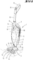
- Fig. 1 shows a soil cultivation device 1 according to the invention, which is designed here as a hand-held vacuum cleaner by way of example.
- the soil cultivation device 1 has a base device 2 and an attachment 3 detachably connected to it.
- the base device 2 and the attachment 3 are detachably connected to one another via a connection area 20.
- the base device 2 has a handle 18 with a handle 19, by means of which a user can push the soil cultivation device 1 over a ground surface to be worked during normal soil cultivation.
- the user usually guides the soil cultivation device 1 away from and towards himself in alternating back and forth movements.
- a selector switch 10 is also provided on the handle 19, which is used to switch the soil cultivation device 1 on and off and / or to set a soil cultivation mode of the soil cultivation device 1.
- the attachment 3 has wheels 17 which facilitate the displacement of the soil cultivation device 1 over the soil surface to be worked. Furthermore, a suction mouth 15 is formed on the attachment 3, through which suction material can be taken up in the attachment 3 or the soil cultivation device 1. A floor treatment element 21, here a rotating cleaning brush, is assigned to the suction mouth 15.
- the base device 2 there is a dust collecting container 9, a motor-blower unit, the motor of which represents a first electrical load 4, and one between the dust-collecting container 9 and the motor-blower unit formed suction channel 16.
- the suction channel 16 also comprises a section from the connection area 20 to the dust collection container 9.
- the motor / fan unit or the suction channel 16 is fluidically connected to the attachment 3 or its suction mouth 15 via the dust collection container 9 and the connection area 20 connected.
- suction material can be sucked up from a floor surface to be cleaned, whereby the suction material passes through the suction mouth 15 into the attachment 3, then flows through the connection area 20 into the base device 2 and there in the dust collecting container 9 (on a filter element (not shown, for example a dust filter bag) is deposited and collected. Since the suction material remains inside the dust collecting container 9, only cleaned air reaches the motor / blower unit from the dust collecting container 9, that is to say through the suction channel 16 formed in between.
- the front-end device 3 also has an identification element 22 which can be read out by an assigned sensor 12 of the base device 2.
- the identification element 22 is here, for example, a barcode which contains information about the type of the attachment 3, including, for example, information on electrical loads 5 of the attachment 3, for example also a maximum power consumption of the respective load 5.
- an accumulator 6, a control device 7 and a data memory 8 are also provided.
- the accumulator 6 is used to supply the electrical consumers 4 of the base device 2 and the electrical consumers 5 of the front-end device 3 with energy.
- the control device 7 is connected on the one hand to the accumulator 6 and on the other hand to the electrical consumers 4, 5 of the base unit 2 and the attachment 3 in order to control the power consumption of the consumers 4, 5 and to monitor a power output of the accumulator 6.
- the control device 7 accesses the data memory 8. This contains a file with defined rankings of the consumers 4, 5, the ranking influencing the power consumption of the consumers 4, 5 in such a way that a consumer 4, 5 is preferably supplied with electrical energy.
- a consumer 4, 5 defined as priority is preferably or completely supplied with the power that it needs for its current operation. Should a situation arise in which a power consumption total of several consumers 4.5 exceeds a defined maximum power output of the accumulator 6, a consumer 4.5 defined as priority is first and preferably supplied with its required energy, while a consumer defined as subordinate is only partially supplied and / or is supplied with energy with a time delay. For this purpose, the power consumption of the consumer 4, 5 defined as subordinate in the order of priority is reduced.
- the ranking of the energy supply to consumers 4, 5 stored in data memory 8 is defined in relation to the situation. This means, for example, that different rankings can be defined for different operating functions or soil cultivation modes of the soil cultivation device 1.
- the operational function of the soil cultivation device 1 can be, for example, starting a consumer 4, 5.
- a processing mode can be, for example, a hard floor cleaning mode for cleaning a hard floor or a carpet cleaning mode for cleaning a carpet.
- the operating functions or tillage modes require different power settings of the consumers 4, 5.
- the ranking of the consumers 4, 5 can also be used for different heights of the suction mouth 15 above the surface to be processed, for a negative pressure within the suction channel 16, a frictional resistance between the attachment 3 and the surface to be cleaned (pushing force) and for the type of The area to be processed or the type of attachment 3 currently connected to the base unit 2 can be defined.
- the soil cultivation device 1 has a plurality of sensors 11, 12, 13, 14 which indicate a current situation, operating function and / or a current soil cultivation mode of the soil cultivation device 1 can recognize.
- the detected information serves as the basis for the control by the control device 7.
- the sensors 11, 12, 13, 14 here include, for example, a sensor 11, which is designed as a pressure sensor and measures a pressure in the suction channel 16, and another sensor 12, which the type of attached attachment 3 is detected by reading the identification element 22 of attachment 3, a sensor 13 for detecting a type of soil of the floor area to be worked, and sensors 14 which measure the current power consumption of consumers 4, 5, namely here, for example, the motor / fan Unit of the base device 2 and a motor for driving the soil cultivation element 21 of the attachment 3.
- a first situation of the soil cultivation device 1 can include, for example, a start of the motor / blower unit, ie the consumer 4, of the base device 2.
- a relatively high power is drawn from the accumulator 6 for the power-up of the consumer 4.
- the control device 7 prioritizes the power consumption of the consumer 4 based on the data in the data memory 8 stored information is higher than, for example, the power consumption for the operation of the motor of the front attachment 3, ie the second consumer 5.
- the control device 7 allows the consumer 5 of the front attachment 3, for example, to start only with a time delay and, if necessary, to start up more slowly to avoid possible power peaks of the consumer 4 , 5 not to occur at the same time.
- control device 7 can also recognize at an early stage whether a change in the current power consumption of the consumers 4, 5 is necessary at all. If, for example, a soil cultivation mode is set which in any case requires relatively little power for the consumers 4, 5, the power consumption can possibly remain unchanged.
- the front attachment 3 can already be switched on, for example, and work on the floor on a carpet. Processing a carpet usually requires a relatively high power consumption of the attachment 3, since the motor of the soil cultivation element 21 requires a relatively large amount of energy to rotate the soil cultivation element 21. This is due to the frictional resistance between the soil working element 21 and the surface to be worked.
- the control device 7 detects the high power consumption of the consumer 5 of the front-end device 3 and prioritizes the power consumption higher than, for example, the power consumption of the consumer 4 of the base device 2, that is to say of the motor / fan unit.
- the control device 7 reduces the power of the motor / fan unit to a lower level Power level to prevent the consumer 5 of the attachment 3 from being switched off.
- the consumer 4 of the base device 2 is operated with less power than before.
- the power difference by which the power consumption of the consumer 4 of the base device 2 was reduced is available in accordance with the consumer 5 of the auxiliary device 3. Switching off both consumers 4, 5 of the base device 2 and the attachment 3 is prevented, since both consumers 4, 5 are operated, but the consumer 4 of the base device 2 with reduced power consumption.
- the motor-fan unit When reducing the power consumption of the consumer 4 of the base device 2, it is furthermore advantageous that the motor-fan unit generates a correspondingly lower negative pressure on the floor surface to be worked and thereby also reduces the pushing force of the floor treatment device 1 on the floor surface to be worked.
- the soil cultivation device 1 can move from a hard floor to a carpet, for example.
- the sensors 13 detect the changed type of floor of the floor surface to be cleaned.
- the consumer 4 of the base device 4 which is assigned to the motor / fan unit, initially showed a maximum power consumption.
- the floor treatment element 21 which is designed as a bristle element, dips into the fibers of the carpet, so that the electrical consumer 5 driving the floor treatment element 21 shows a significantly higher power consumption to the floor treatment element 21 rotate.
- the control device 7 recognizes, on the one hand, the changed type of floor area and, on the other hand, the increased power consumption of the consumer 5 of the attachment 3 due to the measured values of the sensors 13 and 14 and takes from the data memory 8 a ranking of the consumers 4, 5 defined for this situation, which here preferably includes that the power consumption of the consumer 4 of the base device 2, i.e.
- the motor-blower unit is regulated down, in order to compensate for the higher power consumption of the consumer 5 of the attachment 3, that is to say of the motor of the soil cultivation element 21. Due to the reduced fan power of the consumer 4 of the base device 2, the negative pressure at the suction mouth 5 of the attachment 3 also drops at the same time, so that in turn the resistance to movement drops and the brushing power is also reduced overall.
Landscapes
- Engineering & Computer Science (AREA)
- Mechanical Engineering (AREA)
- Power Engineering (AREA)
- Electric Vacuum Cleaner (AREA)
- Charge And Discharge Circuits For Batteries Or The Like (AREA)
- Cultivation Receptacles Or Flower-Pots, Or Pots For Seedlings (AREA)
- Agricultural Machines (AREA)
- Soil Working Implements (AREA)
Claims (9)
- Dispositif de traitement du sol (1) comprenant un dispositif de base (2) et un accessoire (3) qui peut être relié de manière amovible au dispositif de base (2), dans lequel le dispositif de base (2) comporte au moins un premier récepteur électrique (4) et l'accessoire (3) comporte au moins un deuxième récepteur électrique (5), dans lequel le dispositif de traitement du sol (1) comprend en outre un accumulateur (6) pour l'alimentation en énergie des récepteurs électriques (4, 5) et une électronique de protection qui définit une puissance de sortie maximale de l'accumulateur (6) déterminée par les limites de fonctionnement de l'accumulateur (6) laquelle entraînerait en cas de dépassement la mise hors service de l'accessoire (3) ou du dispositif de traitement du sol (1), dans lequel le dispositif de traitement du sol (1) comporte un dispositif de commande (7) pour déterminer et commander une puissance absorbée par le premier récepteur (4) du dispositif de base (2) qui est requise pour son fonctionnement actuel et une puissance absorbée par le deuxième récepteur (5) de l'accessoire (3) qui est requise pour son fonctionnement actuel, dans lequel le dispositif de commande (7) est agencé pour calculer une somme de puissances absorbées à partir des puissances absorbées actuellement requises par le premier récepteur (4) et par le deuxième récepteur (5), de comparer la somme de puissances absorbées avec la puissance de sortie maximale définie de l'accumulateur (6) et, si la puissance de sortie maximale de l'accumulateur (6) est dépassée, de réduire une puissance absorbée d'au moins le premier ou le deuxième récepteur (4, 5) à une valeur différente de zéro, dans lequel le dispositif de base (2) comporte un système de gestion de l'accumulateur qui gère les puissances tirées de l'accumulateur (6), c'est-à-dire qui attribue de la puissance aux premier et deuxième récepteurs (4, 5) en fonction des besoins et distribue la puissance de sortie maximale disponible de l'accumulateur (6) aux premier et deuxième récepteurs (4, 5) de manière à éviter un arrêt du premier ou du deuxième récepteur (4, 5) ou de l'accessoire (3) et/ou du dispositif de base (2), dans lequel le dispositif de traitement du sol (1) comporte une mémoire de données (8) associée au dispositif de commande (7) dans laquelle est mémorisé un ordre de priorité défini des premier et deuxième récepteurs (4, 5) à des fins d'alimentation en énergie, dans lequel le dispositif de commande (7) est agencé pour réduire la puissance absorbée du premier ou du deuxième récepteur (4, 5) qui est défini dans l'ordre de priorité comme ayant une priorité inférieure, lorsqu'un résultat déterminé de comparaison est présent et/ou pour maintenir ou augmenter la puissance absorbée du premier ou du deuxième récepteur (4, 5) défini dans l'ordre de priorité comme ayant une priorité supérieure.
- Dispositif de traitement du sol (1) selon la revendication 1, caractérisé en ce que l'ordre de priorité des premier et deuxième récepteurs (4, 5) est défini en fonction d'une fonction de fonctionnement exécutée par le dispositif de traitement du sol (1) et/ou d'un besoin de service d'un composant du dispositif et/ou d'un type d'accessoire (3) relié au dispositif de base (2) et/ou d'un type de surface à traiter par le dispositif de traitement du sol (1).
- Dispositif de traitement du sol (1) selon la revendication 2, caractérisé en ce que la fonction de service est un démarrage du premier ou du deuxième récepteur (4, 5), en particulier d'un moteur électrique, ou un mode de traitement du sol optimisé pour une tâche spécifique de traitement de sol du dispositif de traitement du sol (1), en particulier un mode de nettoyage de sol dur et/ou un mode de nettoyage de moquette.
- Dispositif de traitement du sol (1) selon la revendication 2 ou 3, caractérisé en ce que le besoin de service du composant du dispositif est un besoin de vidage d'un récipient de collecte de poussière (9) et/ou un besoin de nettoyage d'un filtre à poussière et/ou un besoin de charge de l'accumulateur (6).
- Dispositif de traitement du sol (1) selon l'une des revendications précédentes, caractérisé en ce que le dispositif de commande (7) est agencé pour alimenter le deuxième récepteur (5) en énergie avec un retard dans le temps lorsqu'est déterminée une puissance absorbée du premier récepteur (4) définie comme maximale ou vice versa, et/ou pour augmenter la puissance absorbée du premier ou du deuxième récepteur (4, 5) sur une période de temps définie jusqu'à une valeur prédéterminée.
- Dispositif de traitement du sol (1) selon l'une des revendications précédentes, caractérisé par un sélecteur (10) pour la sélection d'une fonction de fonctionnement du dispositif de traitement du sol (1) par un utilisateur, le dispositif de commande (7) étant agencé pour commander la puissance absorbée des premier et deuxième récepteurs (4, 5) en fonction d'un réglage du sélecteur (10).
- Dispositif de traitement du sol (1) selon la revendication 6, caractérisé en ce que le dispositif de commande (7) est agencé pour comparer une puissance absorbée actuelle réglée par une sélection de fonction de fonctionnement opérée par un utilisateur et/ou par l'utilisateur avec une puissance absorbée des premier et deuxième récepteurs (4, 5) définie comme étant optimale pour une condition environnementale actuelle du dispositif de traitement du sol (1), en particulier pour comparer une puissance absorbée réelle du premier ou deuxième récepteur (4, 5) avec une puissance absorbée cible définie pour le traitement de la surface de sol, et en cas d'écart, pour régler la puissance électrique cible définie du premier ou du deuxième récepteur (4, 5).
- Dispositif de traitement du sol (1) selon l'une des revendications précédentes, caractérisé par un système de capteur(s) qui comporte un ou plusieurs capteurs (11, 12, 13, 14) choisis dans le groupe : capteur de distance pour détecter la hauteur du sol d'une bouche d'aspiration (15) de l'accessoire (3) par rapport à une surface à nettoyer, capteur de pression (11) pour mesurer une pression dans un canal d'aspiration (16) du dispositif de traitement du sol (1), capteur (12) pour détecter un élément d'identification électronique ou optique (22) de l'accessoire (3), capteur de force de poussée pour mesurer une force de poussée surgissant entre l'accessoire (3) et une surface de sol à nettoyer, capteur de type de sol (13) en particulier capteur optique ou capteur à ultrasons pour détecter un signal lumineux ou ultrasonore diffusé par une surface de sol à nettoyer, capteur de courant (14) pour mesurer un courant absorbé par le premier ou le deuxième récepteur (4, 5).
- Dispositif de traitement du sol (1) selon la revendication 8, caractérisé en ce que le dispositif de commande (7) est agencé pour commander une puissance absorbée des premier et deuxième récepteurs (4, 5) en fonction d'un résultat de détection d'un ou plusieurs capteurs (11, 12, 13, 14).
Applications Claiming Priority (1)
| Application Number | Priority Date | Filing Date | Title |
|---|---|---|---|
| DE102018115669.3A DE102018115669A1 (de) | 2018-06-28 | 2018-06-28 | Bodenbearbeitungsgerät mit einem Basisgerät und einem lösbar mit dem Basisgerät verbindbaren Vorsatzgerät |
Publications (2)
| Publication Number | Publication Date |
|---|---|
| EP3588732A1 EP3588732A1 (fr) | 2020-01-01 |
| EP3588732B1 true EP3588732B1 (fr) | 2020-12-23 |
Family
ID=66951855
Family Applications (1)
| Application Number | Title | Priority Date | Filing Date |
|---|---|---|---|
| EP19180752.8A Active EP3588732B1 (fr) | 2018-06-28 | 2019-06-18 | Appareil de traitement du sol doté d'un appareil de base et d'un appareil accessoire raccordable de manière amovible à l'appareil de base |
Country Status (6)
| Country | Link |
|---|---|
| EP (1) | EP3588732B1 (fr) |
| JP (1) | JP2020000855A (fr) |
| CN (1) | CN110652247B (fr) |
| DE (1) | DE102018115669A1 (fr) |
| ES (1) | ES2848863T3 (fr) |
| TW (1) | TW202017525A (fr) |
Families Citing this family (9)
| Publication number | Priority date | Publication date | Assignee | Title |
|---|---|---|---|---|
| DE102020114660A1 (de) * | 2020-06-02 | 2021-12-02 | Vorwerk & Co. Interholding Gesellschaft mit beschränkter Haftung | Sich selbsttätig fortbewegendes Bodenbearbeitungsgerät mit einer Umgebungskarte |
| DE102020121078A1 (de) * | 2020-08-11 | 2022-02-17 | Vorwerk & Co. Interholding Gesellschaft mit beschränkter Haftung | System aus zwei elektromotorisch betriebenen Haushaltsgeräten |
| CN112641376A (zh) * | 2020-12-11 | 2021-04-13 | 珠海格力电器股份有限公司 | 吸尘器的控制方法及吸尘器 |
| CN116634912A (zh) * | 2020-12-23 | 2023-08-22 | 新埃莫斯欧洲有限责任公司 | 电动抽吸头 |
| DE102021127444A1 (de) | 2021-10-22 | 2023-04-27 | Hamm Ag | Verfahren zum Betreiben einer Bodenbearbeitungsmaschine |
| ES2995177T3 (en) * | 2021-12-29 | 2025-02-07 | Vorwerk Co Interholding | Cleaning system comprising a base device and at least one accessory |
| CN117297406A (zh) * | 2022-06-22 | 2023-12-29 | 浙江齐享科技有限公司 | 一种自清洁系统、洗地机及工作方法 |
| GB2624432A (en) * | 2022-11-18 | 2024-05-22 | Dyson Technology Ltd | An appliance |
| GB2624433A (en) * | 2022-11-18 | 2024-05-22 | Dyson Technology Ltd | An appliance |
Family Cites Families (7)
| Publication number | Priority date | Publication date | Assignee | Title |
|---|---|---|---|---|
| GB9814373D0 (en) * | 1998-07-02 | 1998-09-02 | Switched Reluctance Drives Ltd | Cleaning apparatus and method with soft-starting |
| WO2004032696A2 (fr) * | 2002-10-10 | 2004-04-22 | Polar Light Limited | Procede et appareil pour commander l'alimentation d'un dispositif |
| US7203993B2 (en) * | 2003-12-23 | 2007-04-17 | The Hoover Company | Suction nozzle height adjustment and control arrangement |
| DE102005045309A1 (de) * | 2005-09-16 | 2007-03-22 | Alfred Kärcher Gmbh & Co. Kg | Sauggerät |
| DE102010000573B4 (de) * | 2010-02-26 | 2022-06-23 | Vorwerk & Co. Interholding Gmbh | Verfahren zur Leistungssteuerung eines Saug-/Kehrgeräts |
| PL3011883T3 (pl) * | 2014-10-20 | 2019-09-30 | Koninklijke Philips N.V. | Urządzenie do czyszczenia podłogi |
| CN206700117U (zh) * | 2016-11-16 | 2017-12-05 | 九阳股份有限公司 | 一种扫地机 |
-
2018
- 2018-06-28 DE DE102018115669.3A patent/DE102018115669A1/de not_active Withdrawn
-
2019
- 2019-06-10 CN CN201910495393.0A patent/CN110652247B/zh active Active
- 2019-06-14 TW TW108120741A patent/TW202017525A/zh unknown
- 2019-06-17 JP JP2019111790A patent/JP2020000855A/ja active Pending
- 2019-06-18 ES ES19180752T patent/ES2848863T3/es active Active
- 2019-06-18 EP EP19180752.8A patent/EP3588732B1/fr active Active
Non-Patent Citations (1)
| Title |
|---|
| None * |
Also Published As
| Publication number | Publication date |
|---|---|
| CN110652247B (zh) | 2022-04-12 |
| ES2848863T3 (es) | 2021-08-12 |
| TW202017525A (zh) | 2020-05-16 |
| DE102018115669A1 (de) | 2020-01-02 |
| EP3588732A1 (fr) | 2020-01-01 |
| CN110652247A (zh) | 2020-01-07 |
| JP2020000855A (ja) | 2020-01-09 |
Similar Documents
| Publication | Publication Date | Title |
|---|---|---|
| EP3588732B1 (fr) | Appareil de traitement du sol doté d'un appareil de base et d'un appareil accessoire raccordable de manière amovible à l'appareil de base | |
| DE102010000573B4 (de) | Verfahren zur Leistungssteuerung eines Saug-/Kehrgeräts | |
| EP3440977B1 (fr) | Robot de nettoyage avec système de gestion des accumulateurs d'energie. | |
| EP3569124B1 (fr) | Appareil de nettoyage | |
| EP3162266B1 (fr) | Appareil de nettoyage et procédé pour utiliser l'appareil de nettoyage | |
| EP3440978B1 (fr) | Procédé de fonctionnement d'un appareil de nettoyage en mouvement de manière automatique | |
| EP2875767B1 (fr) | Procédé destiné au fonctionnement d'un aspirateur et aspirateur | |
| EP2229088B1 (fr) | Procédé pour interpréter un signal de particules, et buse aspirante pour un aspirateur | |
| EP3430701B1 (fr) | Appareil ménager et procédé de fonctionnement d'un appareil ménager | |
| EP3441842A1 (fr) | Procédé de fonctionnement d'un appareil de traitement du sol mobile automatique | |
| EP3479745B1 (fr) | Procédé de fonctionnement d'un entraînement électrique, de préférence d'un ventilateur et / ou d'une brosse d'un aspirateur ou d'un aspirateur robot | |
| EP4186403A1 (fr) | Système composé d'un appareil de traitement du sol, d'un dispositif accumulateur et d'au moins un appareil accessoire | |
| DE102016101004A1 (de) | Haushaltsreinigungsgerät und Basisstation für Haushaltsreinigungsgerät | |
| DE102007021299A1 (de) | Verfahren und Vorrichtung zum Steuern der Drehzahl zumindest eines Elektromotors in einem mobilen Gerät, insbesondere in einer Saugbürstenvorrichtung oder einem Staubsammelroboter | |
| DE202024101949U1 (de) | Baugruppe zur Reinigung von verwickelten Gegenständen, Reinigungsbaugruppe und Oberflächenreinigungsgerät | |
| EP4358814B1 (fr) | Procédé de nettoyage amélioré d'une région spatialement délimitée | |
| EP2946711A1 (fr) | Procédé de fonctionnement d'un aspirateur et aspirateur | |
| EP3954265B1 (fr) | Système comprenant un appareil électroménager et un accumulateur comportant un dispositif d'affichage optique | |
| EP3970584A1 (fr) | Aspirateur, de préférence aspirateur à main | |
| EP3235414A1 (fr) | Procédé d'adaptation de puissance d'un aspirateur à batterie | |
| EP4173539B1 (fr) | Adaptateur pour un appareil de nettoyage à détection d'humidité et procédé de détection d'humidité | |
| EP4029423B1 (fr) | Fonction d'apprentissage pour aspirateurs pourvus d'injecteurs moteur | |
| EP4147624B1 (fr) | Dispositif de nettoyage du sol à détection de sol et procédé | |
| EP4154785A1 (fr) | Appareil de traitement du sol doté d'un composant de rechange remplaçable, ainsi que système composé d'un dispositif de traitement du sol et d'un terminal externe | |
| DE102017103528A1 (de) | System aus einem Gerät und einer Basisstation |
Legal Events
| Date | Code | Title | Description |
|---|---|---|---|
| PUAI | Public reference made under article 153(3) epc to a published international application that has entered the european phase |
Free format text: ORIGINAL CODE: 0009012 |
|
| STAA | Information on the status of an ep patent application or granted ep patent |
Free format text: STATUS: THE APPLICATION HAS BEEN PUBLISHED |
|
| AK | Designated contracting states |
Kind code of ref document: A1 Designated state(s): AL AT BE BG CH CY CZ DE DK EE ES FI FR GB GR HR HU IE IS IT LI LT LU LV MC MK MT NL NO PL PT RO RS SE SI SK SM TR |
|
| AX | Request for extension of the european patent |
Extension state: BA ME |
|
| STAA | Information on the status of an ep patent application or granted ep patent |
Free format text: STATUS: REQUEST FOR EXAMINATION WAS MADE |
|
| 17P | Request for examination filed |
Effective date: 20200327 |
|
| RBV | Designated contracting states (corrected) |
Designated state(s): AL AT BE BG CH CY CZ DE DK EE ES FI FR GB GR HR HU IE IS IT LI LT LU LV MC MK MT NL NO PL PT RO RS SE SI SK SM TR |
|
| GRAP | Despatch of communication of intention to grant a patent |
Free format text: ORIGINAL CODE: EPIDOSNIGR1 |
|
| STAA | Information on the status of an ep patent application or granted ep patent |
Free format text: STATUS: GRANT OF PATENT IS INTENDED |
|
| RIC1 | Information provided on ipc code assigned before grant |
Ipc: A47L 5/30 20060101ALI20200618BHEP Ipc: A47L 9/04 20060101ALI20200618BHEP Ipc: A47L 9/00 20060101ALI20200618BHEP Ipc: H02J 3/14 20060101ALN20200618BHEP Ipc: H02J 11/00 20060101ALI20200618BHEP Ipc: A47L 9/28 20060101ALI20200618BHEP Ipc: A47L 11/00 20060101ALI20200618BHEP Ipc: H02J 7/00 20060101AFI20200618BHEP |
|
| INTG | Intention to grant announced |
Effective date: 20200713 |
|
| GRAS | Grant fee paid |
Free format text: ORIGINAL CODE: EPIDOSNIGR3 |
|
| GRAA | (expected) grant |
Free format text: ORIGINAL CODE: 0009210 |
|
| STAA | Information on the status of an ep patent application or granted ep patent |
Free format text: STATUS: THE PATENT HAS BEEN GRANTED |
|
| AK | Designated contracting states |
Kind code of ref document: B1 Designated state(s): AL AT BE BG CH CY CZ DE DK EE ES FI FR GB GR HR HU IE IS IT LI LT LU LV MC MK MT NL NO PL PT RO RS SE SI SK SM TR |
|
| REG | Reference to a national code |
Ref country code: GB Ref legal event code: FG4D Free format text: NOT ENGLISH |
|
| REG | Reference to a national code |
Ref country code: DE Ref legal event code: R096 Ref document number: 502019000571 Country of ref document: DE |
|
| REG | Reference to a national code |
Ref country code: AT Ref legal event code: REF Ref document number: 1348660 Country of ref document: AT Kind code of ref document: T Effective date: 20210115 |
|
| REG | Reference to a national code |
Ref country code: IE Ref legal event code: FG4D Free format text: LANGUAGE OF EP DOCUMENT: GERMAN |
|
| PG25 | Lapsed in a contracting state [announced via postgrant information from national office to epo] |
Ref country code: RS Free format text: LAPSE BECAUSE OF FAILURE TO SUBMIT A TRANSLATION OF THE DESCRIPTION OR TO PAY THE FEE WITHIN THE PRESCRIBED TIME-LIMIT Effective date: 20201223 Ref country code: FI Free format text: LAPSE BECAUSE OF FAILURE TO SUBMIT A TRANSLATION OF THE DESCRIPTION OR TO PAY THE FEE WITHIN THE PRESCRIBED TIME-LIMIT Effective date: 20201223 Ref country code: GR Free format text: LAPSE BECAUSE OF FAILURE TO SUBMIT A TRANSLATION OF THE DESCRIPTION OR TO PAY THE FEE WITHIN THE PRESCRIBED TIME-LIMIT Effective date: 20210324 Ref country code: NO Free format text: LAPSE BECAUSE OF FAILURE TO SUBMIT A TRANSLATION OF THE DESCRIPTION OR TO PAY THE FEE WITHIN THE PRESCRIBED TIME-LIMIT Effective date: 20210323 |
|
| REG | Reference to a national code |
Ref country code: NL Ref legal event code: MP Effective date: 20201223 |
|
| PG25 | Lapsed in a contracting state [announced via postgrant information from national office to epo] |
Ref country code: BG Free format text: LAPSE BECAUSE OF FAILURE TO SUBMIT A TRANSLATION OF THE DESCRIPTION OR TO PAY THE FEE WITHIN THE PRESCRIBED TIME-LIMIT Effective date: 20210323 Ref country code: SE Free format text: LAPSE BECAUSE OF FAILURE TO SUBMIT A TRANSLATION OF THE DESCRIPTION OR TO PAY THE FEE WITHIN THE PRESCRIBED TIME-LIMIT Effective date: 20201223 Ref country code: LV Free format text: LAPSE BECAUSE OF FAILURE TO SUBMIT A TRANSLATION OF THE DESCRIPTION OR TO PAY THE FEE WITHIN THE PRESCRIBED TIME-LIMIT Effective date: 20201223 |
|
| PG25 | Lapsed in a contracting state [announced via postgrant information from national office to epo] |
Ref country code: NL Free format text: LAPSE BECAUSE OF FAILURE TO SUBMIT A TRANSLATION OF THE DESCRIPTION OR TO PAY THE FEE WITHIN THE PRESCRIBED TIME-LIMIT Effective date: 20201223 Ref country code: HR Free format text: LAPSE BECAUSE OF FAILURE TO SUBMIT A TRANSLATION OF THE DESCRIPTION OR TO PAY THE FEE WITHIN THE PRESCRIBED TIME-LIMIT Effective date: 20201223 |
|
| REG | Reference to a national code |
Ref country code: LT Ref legal event code: MG9D |
|
| PG25 | Lapsed in a contracting state [announced via postgrant information from national office to epo] |
Ref country code: EE Free format text: LAPSE BECAUSE OF FAILURE TO SUBMIT A TRANSLATION OF THE DESCRIPTION OR TO PAY THE FEE WITHIN THE PRESCRIBED TIME-LIMIT Effective date: 20201223 Ref country code: SM Free format text: LAPSE BECAUSE OF FAILURE TO SUBMIT A TRANSLATION OF THE DESCRIPTION OR TO PAY THE FEE WITHIN THE PRESCRIBED TIME-LIMIT Effective date: 20201223 Ref country code: SK Free format text: LAPSE BECAUSE OF FAILURE TO SUBMIT A TRANSLATION OF THE DESCRIPTION OR TO PAY THE FEE WITHIN THE PRESCRIBED TIME-LIMIT Effective date: 20201223 Ref country code: PT Free format text: LAPSE BECAUSE OF FAILURE TO SUBMIT A TRANSLATION OF THE DESCRIPTION OR TO PAY THE FEE WITHIN THE PRESCRIBED TIME-LIMIT Effective date: 20210423 Ref country code: RO Free format text: LAPSE BECAUSE OF FAILURE TO SUBMIT A TRANSLATION OF THE DESCRIPTION OR TO PAY THE FEE WITHIN THE PRESCRIBED TIME-LIMIT Effective date: 20201223 Ref country code: LT Free format text: LAPSE BECAUSE OF FAILURE TO SUBMIT A TRANSLATION OF THE DESCRIPTION OR TO PAY THE FEE WITHIN THE PRESCRIBED TIME-LIMIT Effective date: 20201223 |
|
| REG | Reference to a national code |
Ref country code: ES Ref legal event code: FG2A Ref document number: 2848863 Country of ref document: ES Kind code of ref document: T3 Effective date: 20210812 |
|
| PG25 | Lapsed in a contracting state [announced via postgrant information from national office to epo] |
Ref country code: PL Free format text: LAPSE BECAUSE OF FAILURE TO SUBMIT A TRANSLATION OF THE DESCRIPTION OR TO PAY THE FEE WITHIN THE PRESCRIBED TIME-LIMIT Effective date: 20201223 |
|
| REG | Reference to a national code |
Ref country code: DE Ref legal event code: R097 Ref document number: 502019000571 Country of ref document: DE |
|
| PG25 | Lapsed in a contracting state [announced via postgrant information from national office to epo] |
Ref country code: IS Free format text: LAPSE BECAUSE OF FAILURE TO SUBMIT A TRANSLATION OF THE DESCRIPTION OR TO PAY THE FEE WITHIN THE PRESCRIBED TIME-LIMIT Effective date: 20210423 |
|
| PG25 | Lapsed in a contracting state [announced via postgrant information from national office to epo] |
Ref country code: AL Free format text: LAPSE BECAUSE OF FAILURE TO SUBMIT A TRANSLATION OF THE DESCRIPTION OR TO PAY THE FEE WITHIN THE PRESCRIBED TIME-LIMIT Effective date: 20201223 |
|
| PLBE | No opposition filed within time limit |
Free format text: ORIGINAL CODE: 0009261 |
|
| STAA | Information on the status of an ep patent application or granted ep patent |
Free format text: STATUS: NO OPPOSITION FILED WITHIN TIME LIMIT |
|
| PG25 | Lapsed in a contracting state [announced via postgrant information from national office to epo] |
Ref country code: DK Free format text: LAPSE BECAUSE OF FAILURE TO SUBMIT A TRANSLATION OF THE DESCRIPTION OR TO PAY THE FEE WITHIN THE PRESCRIBED TIME-LIMIT Effective date: 20201223 |
|
| 26N | No opposition filed |
Effective date: 20210924 |
|
| PG25 | Lapsed in a contracting state [announced via postgrant information from national office to epo] |
Ref country code: CZ Free format text: LAPSE BECAUSE OF NON-PAYMENT OF DUE FEES Effective date: 20210618 Ref country code: MC Free format text: LAPSE BECAUSE OF FAILURE TO SUBMIT A TRANSLATION OF THE DESCRIPTION OR TO PAY THE FEE WITHIN THE PRESCRIBED TIME-LIMIT Effective date: 20201223 |
|
| PG25 | Lapsed in a contracting state [announced via postgrant information from national office to epo] |
Ref country code: SI Free format text: LAPSE BECAUSE OF FAILURE TO SUBMIT A TRANSLATION OF THE DESCRIPTION OR TO PAY THE FEE WITHIN THE PRESCRIBED TIME-LIMIT Effective date: 20201223 |
|
| REG | Reference to a national code |
Ref country code: BE Ref legal event code: MM Effective date: 20210630 |
|
| PG25 | Lapsed in a contracting state [announced via postgrant information from national office to epo] |
Ref country code: LU Free format text: LAPSE BECAUSE OF NON-PAYMENT OF DUE FEES Effective date: 20210618 |
|
| PG25 | Lapsed in a contracting state [announced via postgrant information from national office to epo] |
Ref country code: IE Free format text: LAPSE BECAUSE OF NON-PAYMENT OF DUE FEES Effective date: 20210618 |
|
| PG25 | Lapsed in a contracting state [announced via postgrant information from national office to epo] |
Ref country code: IS Free format text: LAPSE BECAUSE OF FAILURE TO SUBMIT A TRANSLATION OF THE DESCRIPTION OR TO PAY THE FEE WITHIN THE PRESCRIBED TIME-LIMIT Effective date: 20210423 |
|
| PG25 | Lapsed in a contracting state [announced via postgrant information from national office to epo] |
Ref country code: BE Free format text: LAPSE BECAUSE OF NON-PAYMENT OF DUE FEES Effective date: 20210630 |
|
| REG | Reference to a national code |
Ref country code: CH Ref legal event code: PL |
|
| PG25 | Lapsed in a contracting state [announced via postgrant information from national office to epo] |
Ref country code: LI Free format text: LAPSE BECAUSE OF NON-PAYMENT OF DUE FEES Effective date: 20220630 Ref country code: CH Free format text: LAPSE BECAUSE OF NON-PAYMENT OF DUE FEES Effective date: 20220630 |
|
| P01 | Opt-out of the competence of the unified patent court (upc) registered |
Effective date: 20230517 |
|
| PG25 | Lapsed in a contracting state [announced via postgrant information from national office to epo] |
Ref country code: CY Free format text: LAPSE BECAUSE OF FAILURE TO SUBMIT A TRANSLATION OF THE DESCRIPTION OR TO PAY THE FEE WITHIN THE PRESCRIBED TIME-LIMIT Effective date: 20201223 |
|
| PG25 | Lapsed in a contracting state [announced via postgrant information from national office to epo] |
Ref country code: HU Free format text: LAPSE BECAUSE OF FAILURE TO SUBMIT A TRANSLATION OF THE DESCRIPTION OR TO PAY THE FEE WITHIN THE PRESCRIBED TIME-LIMIT; INVALID AB INITIO Effective date: 20190618 |
|
| GBPC | Gb: european patent ceased through non-payment of renewal fee |
Effective date: 20230618 |
|
| PG25 | Lapsed in a contracting state [announced via postgrant information from national office to epo] |
Ref country code: MK Free format text: LAPSE BECAUSE OF FAILURE TO SUBMIT A TRANSLATION OF THE DESCRIPTION OR TO PAY THE FEE WITHIN THE PRESCRIBED TIME-LIMIT Effective date: 20201223 Ref country code: GB Free format text: LAPSE BECAUSE OF NON-PAYMENT OF DUE FEES Effective date: 20230618 |
|
| PG25 | Lapsed in a contracting state [announced via postgrant information from national office to epo] |
Ref country code: TR Free format text: LAPSE BECAUSE OF FAILURE TO SUBMIT A TRANSLATION OF THE DESCRIPTION OR TO PAY THE FEE WITHIN THE PRESCRIBED TIME-LIMIT Effective date: 20201223 |
|
| PG25 | Lapsed in a contracting state [announced via postgrant information from national office to epo] |
Ref country code: MT Free format text: LAPSE BECAUSE OF FAILURE TO SUBMIT A TRANSLATION OF THE DESCRIPTION OR TO PAY THE FEE WITHIN THE PRESCRIBED TIME-LIMIT Effective date: 20201223 |
|
| PGFP | Annual fee paid to national office [announced via postgrant information from national office to epo] |
Ref country code: DE Payment date: 20250618 Year of fee payment: 7 |
|
| PGFP | Annual fee paid to national office [announced via postgrant information from national office to epo] |
Ref country code: FR Payment date: 20250626 Year of fee payment: 7 |
|
| REG | Reference to a national code |
Ref country code: AT Ref legal event code: MM01 Ref document number: 1348660 Country of ref document: AT Kind code of ref document: T Effective date: 20240618 |
|
| PGFP | Annual fee paid to national office [announced via postgrant information from national office to epo] |
Ref country code: ES Payment date: 20250718 Year of fee payment: 7 |
|
| PGFP | Annual fee paid to national office [announced via postgrant information from national office to epo] |
Ref country code: IT Payment date: 20250630 Year of fee payment: 7 |
|
| PG25 | Lapsed in a contracting state [announced via postgrant information from national office to epo] |
Ref country code: AT Free format text: LAPSE BECAUSE OF NON-PAYMENT OF DUE FEES Effective date: 20240618 |
|
| PGFP | Annual fee paid to national office [announced via postgrant information from national office to epo] |
Ref country code: AT Payment date: 20260410 Year of fee payment: 5 |