EP3588978B1 - Procédé de fabrication d'une coque métallique pour un dispositif auditif - Google Patents
Procédé de fabrication d'une coque métallique pour un dispositif auditif Download PDFInfo
- Publication number
- EP3588978B1 EP3588978B1 EP18178959.5A EP18178959A EP3588978B1 EP 3588978 B1 EP3588978 B1 EP 3588978B1 EP 18178959 A EP18178959 A EP 18178959A EP 3588978 B1 EP3588978 B1 EP 3588978B1
- Authority
- EP
- European Patent Office
- Prior art keywords
- preform
- metal shell
- opening
- main body
- label
- Prior art date
- Legal status (The legal status is an assumption and is not a legal conclusion. Google has not performed a legal analysis and makes no representation as to the accuracy of the status listed.)
- Active
Links
Images

Classifications
-
- H—ELECTRICITY
- H04—ELECTRIC COMMUNICATION TECHNIQUE
- H04R—LOUDSPEAKERS, MICROPHONES, GRAMOPHONE PICK-UPS OR LIKE ACOUSTIC ELECTROMECHANICAL TRANSDUCERS; ELECTRIC HEARING AIDS; PUBLIC ADDRESS SYSTEMS
- H04R25/00—Electric hearing aids
- H04R25/65—Housing parts, e.g. shells, tips or moulds, or their manufacture
- H04R25/658—Manufacture of housing parts
-
- H—ELECTRICITY
- H04—ELECTRIC COMMUNICATION TECHNIQUE
- H04R—LOUDSPEAKERS, MICROPHONES, GRAMOPHONE PICK-UPS OR LIKE ACOUSTIC ELECTROMECHANICAL TRANSDUCERS; ELECTRIC HEARING AIDS; PUBLIC ADDRESS SYSTEMS
- H04R2225/00—Details of deaf aids covered by H04R25/00, not provided for in any of its subgroups
- H04R2225/025—In the ear hearing aids [ITE] hearing aids
-
- H—ELECTRICITY
- H04—ELECTRIC COMMUNICATION TECHNIQUE
- H04R—LOUDSPEAKERS, MICROPHONES, GRAMOPHONE PICK-UPS OR LIKE ACOUSTIC ELECTROMECHANICAL TRANSDUCERS; ELECTRIC HEARING AIDS; PUBLIC ADDRESS SYSTEMS
- H04R25/00—Electric hearing aids
- H04R25/65—Housing parts, e.g. shells, tips or moulds, or their manufacture
- H04R25/652—Ear tips; Ear moulds
Definitions
- the invention relates to a method for manufacturing a metal shell for a hearing device.
- Ear canals of different users have different size and contour. It has been desired for the users to customize a hearing device such as a hearing aid or an earpiece for acoustic coupling, especially a shell for the hearing device. With development of a 3D printing process such as a Selective Laser Sintering (SLS), a customized hearing device becomes a reality because it is cost-effective and time-effective.
- a metal shell for the hearing device is produced from metal powder using the SLS process. Since metal has a high strength a metal shell may have a thin wall.
- the metal shell for the hearing device generally has at least two openings: a first opening and a second opening.
- the first opening is usually large and configured for attaching a faceplate or introducing an electronics module or an acoustic component.
- the second opening is usually small and functions as a sound outlet.
- the second opening functioning as the sound outlet is positioned at the inner side of the metal shell facing the eardrum of the user when the hearing device is placed into the ear canal of the user.
- the first opening is positioned at the outer side of the metal shell opposite to the inner side of the metal shell.
- a metal shell Before manufacturing a metal shell, it is necessary to acquire some data regarding the geometry of the ear canal of the user. This data may be obtained by scanning an impression of the ear canal of the user by means of an ear canal scanner or any other technique.
- a preform is printed by the SLS process.
- the surface of the preform is then smoothened by vibratory grinding. Vibratory grinding is contemporarily applied to a multitude of different preforms and smoothens their surfaces. Then, manual polishing of the contour and the openings of the preform is conducted. After sand blasting the preform, the final shell is obtained.
- the functional components such as the electronics module or the acoustic component may now be assembled into the metal shell to form the complete hearing device.
- an identification information such as an identification number is necessary for each shell.
- the ID has to be legible.
- a serial number of the final hearing device is applied on the shell surface. The serial number is unique for each single hearing device.
- the shell ID is not necessary any more.
- the ID is usually printed as a 3D structure on the inside of the metal shell and is not removed by grinding.
- a litz wire of a functional component may be damaged due to its friction with the ID.
- the ID printed on the inside of the metal shell contains very limited information about the fabricating process. If more information has to be connected to the metal shell, additional writing has to be placed on the metal shell without interfering with any manufacturing step or the appearance of the hearing device.
- the grinding material may enter into the inside of the preform of the metal shell and it is difficult or nearly impossible to remove the material from the preform of the metal shell.
- EP2037702 proposes to use a plastic plug for protecting a contour of an opening of a plastic shell during a tumbling process.
- the plug can be fabricated together with the plastic shell.
- Supporting members of the plug comprise breakpoints which allow pushing the plug into the opening after fabrication of the plastic shell prior to the tumbling process. After tumbling, the plug is manually removed. Due to the softness of plastic shells a plug can be pushed in the opening and engage with the contour of the opening. With harder materials such as metals this is not possible.
- US 2017/0280260 A1 discloses a method for producing a hearing device shell comprising an additive manufacturing step in which the shell is formed using titanium by laser sintering or 3D-printing, and a subtractive manufacturing step comprising buffing or polishing of an outer surface of the shell.
- US 2015/382123 A1 discloses a method for producing a comfort fit personalized earphone comprising a three dimensional printing process of an earpiece based on a 3D model created using ear images transmitted by mobile communication.
- a laser cutter may be employed for fabricating 2d design elements such as veneer prints and holographic images.
- WO 2017/157851 A1 discloses a device for manufacturing a sacrificial mold for moulding an object, wherein the mold manufacturing uses 3D printing which may include metal laser sintering.
- the sacrificial mould can provide an enclosure of the moulded object and may also comprise traceability features that may not be available to the enclosed object, which can include barcodes, dot matrix codes, laser engravings, colour codings or markings.
- An objective of the present invention is to overcome at least one of the above-mentioned problems of metal shell production.
- it is possible to manufacture simply, efficiently and reliably a metal shell for a hearing device.
- Another objective of the present invention is to provide a method for manufacturing a metal shell for a hearing device. According to the method of the present invention, it is possible to provide a label comprising the identification information of the metal shell which can be easily read and does not take up any space in the hearing device.
- a further objective of the present invention is to provide a method for manufacturing a metal shell for a hearing device. According to the method of the present invention, it is possible to provide a protective element for preventing the grinding materials from entering into a preform of the metal shell.
- a method for manufacturing a metal shell for a hearing device comprising:
- the second opening is smaller than the first opening and the at least one sacrificial element is located at the second position.
- connection portion between the at least one sacrificial element and the main body of the preform forms breakpoints.
- Fabricating the preform of the metal shell comprises forming the preform by a 3D printing process.
- the 3D printing process is a Selective Laser Sintering (SLS) process.
- SLS Selective Laser Sintering
- smoothening the surface of the preform comprises treating the preform by vibratory grinding.
- the second opening has a circular form and the second opening is shaped at the same time of fabricating the preform of the metal shell.
- the second opening has a circular form and finishing the preform further comprises drilling the second opening.
- the method further comprises generating a design of the metal shell based on data related to an ear canal of a user, the preform of the metal shell is fabricated based the design of the metal shell.
- the at least one sacrificial element comprises a label, and the label has a three-dimensional structure comprising an identification information of the metal shell.
- the label extends outside of the main body of the preform.
- the label is movably attached to the main body of the preform by a chain.
- the label comprises two sides, and the identification information is included on one side of the label and additional information is included on the other side of the label.
- the at least one sacrificial element comprises a protective element extending within the internal cavity defined by the main body of the preform.
- the protective element has a form similar to that of a functional component of the hearing device which is intended to be disposed inside the internal cavity.
- the functional component is a receiver for converting electrical signal into acoustic signal.
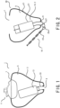
- FIG. 1 shows schematically a hearing device 1 with a metal shell 3 according to the invention.
- the metal shell 3 defines an internal cavity 5.
- the metal shell 3 has at least a first opening 7 and a second opening 9.
- the hearing device 1 further comprises an electronic module 11 attached to the first opening 7 and a receiver 13 disposed within the internal cavity 5 near the second opening 9.
- the electronic module 11 converts acoustic signal into electrical signal and amplifies the electrical signal.
- the receiver 13 converts the electrical signal from the electronic module 11 into the acoustic signal.
- the acoustic signal emitted from the receiver 13 transmits into the ear canal of a user through the second opening 9. Since the first opening 7 is configured for introducing a part of the electronics module 11 into the internal cavity 5 and attaching the electronics module 11 to the metal shell 3, the first opening 7 is relatively large.
- the second opening 9 functions as a sound outlet and thus is relatively small.
- the metal shell 3 is made from a metal material such as titanium or titanium alloy and manufactured with a Selective Laser Sintering (SLS) process based on the data regarding the geometry of the ear canal of the specific user.
- SLS Selective Laser Sintering
- the present invention proposes a method for manufacturing a metal shell for a hearing device.
- one or more sacrificial elements 10.1, 10.2 are added to a preform (i.e., an intermediate shell) of the metal shell during manufacturing of the metal shell and removed from the preform prior to the final assembly of the hearing device.
- FIG. 2 shows schematically a preform of a shell of the hearing device manufactured using a method for manufacturing a metal shell for a hearing device according to the present invention.
- one or more sacrificial elements 10.1, 10.2 are printed on a main body of the preform at the same time of printing the main body of the preform.
- the preform 20 of the metal shell 3 generally comprises a main body 21 printed with the SLS. At least the first opening 7 and the second opening 9 are shaped in the main body 21.
- the preform 20 of the metal shell 3 further comprises a label 23 (i.e. a first sacrificial element 10.1) printed with the SLS on the main body 21 at a position where the second opening 9 is located.
- the label 23 extends outside of the main body 21.
- the label 23 comprising an alphanumeric code is matched to every printed shell, thus associating the metal shell to a hearing device ordered by the specific user.
- typical code on the label 23 is a 4 digit and/or letter code (i.e. ID of the metal shell), which identifies the metal shell in the batch. Since the label 23 extends outside of the main body 21, there is additional space on the other side of the label 23.
- the label 23 may further comprise some additional information such as a size of the openings, surface quality of the metal shell, or other relevant information for manufacturing.
- the other side of the label 23 as shown in FIG 4B comprises the diameter of the second opening 9.
- the label 23 is connected to the main body 21 of the preform 20 by a chain 25, thus yielding a movable or flexible connection between the label 23 and the main body 21 of the preform 20.
- the chain 25 comprises one or more chain link 27 which is also printed with the SLS and is connected to the main body 21 of the preform 20 at the position where the second opening 9 is located.
- the movable or flexible connection between the label 23 and the main body 21 of the preform 20 minimizes print time and ensures the label 23 does not interfere with any post-processing steps such as vibratory grinding, sand blasting or polishing steps.
- the movable or flexible connection also minimizes a space needed in a SLS machine (i.e. a 3D printer) to print the preform because the label 23 may be bent around the preform. If the label 23 would for example extend in the length of the preform, it would require more space.
- the label 23 comprising ID of the metal shell has to be legible at a serializing step, after post-processing steps such as polishing and sand blasting. After the metal shell is serialized, the metal shell ID is not necessary any more.
- the serial number is printed on the metal shell.
- printing at the serializing step is not a 3D-printing as the SLS printing, it is a graphical printing process, for example laser-printing, silk-printing or inkjet-printing. After printing of the serial number there is no further grinding/smoothening step.
- the surface of the metal shell is finished.
- the connection portion between the label 23 or the chain 25 and the main body 21 of the preform 20 forms first fragile breakpoints 29 (as shown in FIG 3 ) so that the label 23 may be easily cut away or broken away from the preform 20.
- the label 23 is printed with the SLS, attached to the main body 21 and extends outside of the main body 21, the label is easily read at a serializing step. Further, the label 23 may be easily cut away or broken away after the metal shell is serialized. No space in the metal shell of the hearing device is taken up, thereby preventing the functional components (in particular the litz wires of the functional components) inside the metal shell from being damaged due to friction contact with the label.
- the label 23 may comprise more information regarding the metal shell since it is printed with digit and/or letter code on both sides. Further, the label 23 has a printed three-dimensional structure and it is possible to prevent the digit and/or letter code on the label from being abrased.
- the preform 20 of the metal shell 3 further comprises a protective element 31 (i.e. a second sacrificial element 10.2) printed with the SLS on the main body 21 at the position where the second opening 9 is located.
- the protective element 31 extends within the internal cavity 5 defined by the main body 21 of the preform 20.
- the internal cavity 5 defined by the main body 21 of the preform 20 is occupied substantially by the protective element 31 and grinding material cannot enter into the internal cavity 5 during smoothening the surface of the preform 20 by vibratory grinding or polishing.
- the protective element 31 preferably has a form similar to that of a functional component (for example the receiver 13) which is intended to be disposed inside the metal shell during assembly.
- the modeling data of the component which is intended to be disposed inside the metal shell during assembly can be used to print the protective element 31.
- the protective element 31 can be accessed and removed from the first opening 7 using a suitable tool, such as tweezers or pliers, after the vibratory grinding. Later, when the components of the hearing device are assembled, a functional element such as the receiver 13 is disposed into the internal cavity 5 and it is acoustically coupled to the second opening 9 directly or by using a connection element 33 such as a small tube.
- a connection element 33 such as a small tube.
- the connection portion between the protective element 31 and the main body 21 of the preform 20 forms second fragile breakpoints 35 (as shown in FIG 3 ) so that the protective element 31 may be easily cut away or broken away from the preform 20.
- the second opening 7 may be shaped in the preform 20 when the preform 20 is printed, or it may be drilled later during finishing the preform.
- the second opening in the preform may have an equal or smaller diameter than the finished second opening. Drilling creates a precise round hole. What is important is that the position of the second opening 7 is known, even if the second opening 7 is not already formed or doesn't have the final diameter when the preform 20 is printed.
- preform 20 of the metal shell 3 is shown to comprise both the label 23 and the protective element 31 at the position where the second opening 9 is located, it should be understood that the preform 20 of the metal shell 3 comprises solely the label 23.
- the preform is fabricated by a Selective Laser Sintering (SLS) process.
- SLS Selective Laser Sintering
- DMLS Direct metal laser sintering
- SLM Selective Laser Melting
Landscapes
- Engineering & Computer Science (AREA)
- Manufacturing & Machinery (AREA)
- Health & Medical Sciences (AREA)
- General Health & Medical Sciences (AREA)
- Neurosurgery (AREA)
- Otolaryngology (AREA)
- Physics & Mathematics (AREA)
- Acoustics & Sound (AREA)
- Signal Processing (AREA)
- Powder Metallurgy (AREA)
Claims (11)
- Procédé de fabrication d'une coque métallique (3) pour un dispositif auditif (1), la coque métallique comprenant une première ouverture (7) et une seconde ouverture (9), le procédé comprenant :- la fabrication d'une préforme (20) de la coque métallique (3), la préforme (20) comprenant un corps principal (21) définissant une cavité interne (5) et au moins un élément sacrificiel (10.1, 10.2) formé sur le corps principal (21), le corps principal (21) ayant une première position où est située la première ouverture (7) et une seconde position où est située la seconde ouverture (9), dans lequel la fabrication de la préforme (20) de la coque métallique (3) comprend la formation de la préforme (20) par un processus d'impression 3D, qui est un processus de frittage sélectif par laser (SLS) ;- le lissage d'une surface de la préforme (20) ; et- la finition de la préforme (20) pour obtenir la coque métallique,dans lequel l'au moins un élément sacrificiel (10.1) comprend une étiquette (23), et l'étiquette a une structure tridimensionnelle comprenant une information d'identification de la coque métallique (3), dans lequel l'étiquette (23) s'étend à l'extérieur du corps principal (21) de la préforme (20) et est fixée de manière mobile au corps principal (21) de la préforme (20) par une chaîne (25), dans lequel la chaîne (25) comprend un ou plusieurs maillons de chaîne (27) qui sont également imprimés avec le SLS et sont reliés au corps principal (21) de la préforme (20) au niveau de la position où est située la seconde ouverture (9) et la finition de la préforme (20) comprend le retrait de l'au moins un élément sacrificiel (10.1, 10.2) .
- Procédé selon la revendication 1, dans lequel la seconde ouverture (9) est plus petite que la première ouverture (7) et l'au moins un élément sacrificiel (10.1, 10.2) est situé au niveau de la seconde position.
- Procédé selon la revendication 1, dans lequel une partie de liaison entre l'au moins un élément sacrificiel (10.1, 10.2) et le corps principal (21) de la préforme (20) forme des points de rupture.
- Procédé selon la revendication 1 dans lequel le lissage de la surface de la préforme (20) comprend le traitement de la préforme (20) par broyage vibratoire.
- Procédé selon la revendication 1 dans lequel la seconde ouverture (9) a une forme circulaire et la seconde ouverture (9) est formée en même temps que la fabrication de la préforme (20) de l'enveloppe métallique (3).
- Procédé selon la revendication 1 dans lequel la seconde ouverture (9) a une forme circulaire et la finition de la préforme (20) comprend en outre le perçage de la seconde ouverture (9).
- Procédé selon la revendication 1 dans lequel le procédé comprend en outre la génération d'une conception de la coque métallique (3) sur la base de données relatives à un conduit auditif d'un utilisateur, la préforme (20) de la coque métallique (3) étant fabriquée sur la base de la conception de la coque métallique (3).
- Procédé selon la revendication 1 dans lequel l'étiquette (23) comprend deux côtés, et l'information d'identification est incluse sur le côté de l'étiquette (23) et des informations supplémentaires sont incluses sur l'autre côté de l'étiquette.
- Procédé selon la revendication 1 dans lequel l'au moins un élément sacrificiel (10.2) comprend un élément de protection (31) s'étendant à l'intérieur de la cavité interne (5) définie par le corps principal (21) de la préforme (20).
- Procédé selon la revendication 9 dans lequel l'élément de protection (31) a une forme similaire à celle d'un composant fonctionnel du dispositif auditif qui est destiné à être disposé à l'intérieur de la cavité interne (5).
- Procédé selon la revendication 10 dans lequel le composant fonctionnel est un récepteur permettant de convertir un signal électrique en signal acoustique.
Priority Applications (1)
| Application Number | Priority Date | Filing Date | Title |
|---|---|---|---|
| EP18178959.5A EP3588978B1 (fr) | 2018-06-21 | 2018-06-21 | Procédé de fabrication d'une coque métallique pour un dispositif auditif |
Applications Claiming Priority (1)
| Application Number | Priority Date | Filing Date | Title |
|---|---|---|---|
| EP18178959.5A EP3588978B1 (fr) | 2018-06-21 | 2018-06-21 | Procédé de fabrication d'une coque métallique pour un dispositif auditif |
Publications (2)
| Publication Number | Publication Date |
|---|---|
| EP3588978A1 EP3588978A1 (fr) | 2020-01-01 |
| EP3588978B1 true EP3588978B1 (fr) | 2024-08-07 |
Family
ID=62750779
Family Applications (1)
| Application Number | Title | Priority Date | Filing Date |
|---|---|---|---|
| EP18178959.5A Active EP3588978B1 (fr) | 2018-06-21 | 2018-06-21 | Procédé de fabrication d'une coque métallique pour un dispositif auditif |
Country Status (1)
| Country | Link |
|---|---|
| EP (1) | EP3588978B1 (fr) |
Family Cites Families (7)
| Publication number | Priority date | Publication date | Assignee | Title |
|---|---|---|---|---|
| US20090067656A1 (en) | 2007-09-12 | 2009-03-12 | Siemens Hearing Instruments Inc. | Protective Finishing Plug For A Hearing Instrument Shell |
| DE102007053540A1 (de) * | 2007-11-09 | 2009-06-10 | Siemens Medical Instruments Pte. Ltd. | In-dem-Ohr Hörgerätgehäuse und dessen Herstellung |
| US20160200044A1 (en) * | 2013-04-24 | 2016-07-14 | The Board Of Regents Of The University Of Texas System | Cartridge-based 3d printing system |
| US20150382123A1 (en) * | 2014-01-16 | 2015-12-31 | Itamar Jobani | System and method for producing a personalized earphone |
| US20170280260A1 (en) * | 2014-09-08 | 2017-09-28 | Sonova Ag | A method for producing a hearing device shell, a hearing device shell and a hearing device |
| DK3429832T3 (da) * | 2016-03-14 | 2021-11-22 | Addifab Aps | Additiv fremstillingsindretning og system til fremstilling af en offerform til dannelse af en genstand |
| EP3586522B1 (fr) * | 2017-02-23 | 2023-01-18 | Sonova AG | Procédé de fabrication d'un boîtier de dispositif auditif |
-
2018
- 2018-06-21 EP EP18178959.5A patent/EP3588978B1/fr active Active
Also Published As
| Publication number | Publication date |
|---|---|
| EP3588978A1 (fr) | 2020-01-01 |
Similar Documents
| Publication | Publication Date | Title |
|---|---|---|
| EP2335426B1 (fr) | Procédé servant à fabriquer un appareil auditif possédant un composant élastique ajusté de façon personnalisée | |
| US20120243701A1 (en) | Concha-Fitting Custom Earplug with Flexible Skin and Filler Material | |
| AU2010306204B2 (en) | Individually tailored soft components | |
| CA2663102A1 (fr) | Procede de production d'un boitiier pour prothese auditive et prothese auditive correspondante | |
| US20050117765A1 (en) | Hearing aid assembly | |
| EP3449646B1 (fr) | Embout auriculaire élastomère personnalisé ayant un apport de matériau secondaire | |
| JP2004508785A (ja) | 耳用装置、同装置の製造方法及び同方法の適用 | |
| CA2412934A1 (fr) | Procede de fabrication d'otoplastiques et otoplastique y relatif | |
| WO2008021289A2 (fr) | Prothèse auditive interne utilisant des joints acoustiques annulaires | |
| US8521319B2 (en) | Method of producing a housing shell or ear mold to be worn in the ear | |
| CN109604602B (zh) | 一种3d打印助听器外壳的制作方法 | |
| EP2083583A1 (fr) | Fabrication d'un couvercle en silicone souple pour la protection d'un instrument auditif | |
| EP2497278B1 (fr) | Prothèse auditive et procédé de fabrication d'une telle prothèse | |
| JP4982488B2 (ja) | 補聴器用長細可変形部材の成形方法およびツール | |
| US20170280260A1 (en) | A method for producing a hearing device shell, a hearing device shell and a hearing device | |
| EP3588978A1 (fr) | Procédé de fabrication d'une coque métallique pour un dispositif auditif | |
| US20050247515A1 (en) | Ear-plug device, method for manufacturing the same and use of such an ear-plug device | |
| US20060039818A1 (en) | Method of forming a die | |
| EP3586522B1 (fr) | Procédé de fabrication d'un boîtier de dispositif auditif | |
| CN117376799A (zh) | 助听器外壳及其设计方法、装置、计算机设备、助听器 | |
| JP4191683B2 (ja) | 耳孔装着用部材の製造方法及び耳孔装着用部材並びにデータ処理プログラム | |
| HK1175914B (en) | Hearing aid and method of fabricating the same |
Legal Events
| Date | Code | Title | Description |
|---|---|---|---|
| PUAI | Public reference made under article 153(3) epc to a published international application that has entered the european phase |
Free format text: ORIGINAL CODE: 0009012 |
|
| STAA | Information on the status of an ep patent application or granted ep patent |
Free format text: STATUS: THE APPLICATION HAS BEEN PUBLISHED |
|
| AK | Designated contracting states |
Kind code of ref document: A1 Designated state(s): AL AT BE BG CH CY CZ DE DK EE ES FI FR GB GR HR HU IE IS IT LI LT LU LV MC MK MT NL NO PL PT RO RS SE SI SK SM TR |
|
| AX | Request for extension of the european patent |
Extension state: BA ME |
|
| STAA | Information on the status of an ep patent application or granted ep patent |
Free format text: STATUS: REQUEST FOR EXAMINATION WAS MADE |
|
| 17P | Request for examination filed |
Effective date: 20200625 |
|
| RBV | Designated contracting states (corrected) |
Designated state(s): AL AT BE BG CH CY CZ DE DK EE ES FI FR GB GR HR HU IE IS IT LI LT LU LV MC MK MT NL NO PL PT RO RS SE SI SK SM TR |
|
| STAA | Information on the status of an ep patent application or granted ep patent |
Free format text: STATUS: EXAMINATION IS IN PROGRESS |
|
| 17Q | First examination report despatched |
Effective date: 20210226 |
|
| GRAP | Despatch of communication of intention to grant a patent |
Free format text: ORIGINAL CODE: EPIDOSNIGR1 |
|
| STAA | Information on the status of an ep patent application or granted ep patent |
Free format text: STATUS: GRANT OF PATENT IS INTENDED |
|
| INTG | Intention to grant announced |
Effective date: 20240221 |
|
| GRAS | Grant fee paid |
Free format text: ORIGINAL CODE: EPIDOSNIGR3 |
|
| GRAA | (expected) grant |
Free format text: ORIGINAL CODE: 0009210 |
|
| STAA | Information on the status of an ep patent application or granted ep patent |
Free format text: STATUS: THE PATENT HAS BEEN GRANTED |
|
| AK | Designated contracting states |
Kind code of ref document: B1 Designated state(s): AL AT BE BG CH CY CZ DE DK EE ES FI FR GB GR HR HU IE IS IT LI LT LU LV MC MK MT NL NO PL PT RO RS SE SI SK SM TR |
|
| REG | Reference to a national code |
Ref country code: GB Ref legal event code: FG4D |
|
| REG | Reference to a national code |
Ref country code: CH Ref legal event code: EP |
|
| REG | Reference to a national code |
Ref country code: IE Ref legal event code: FG4D |
|
| REG | Reference to a national code |
Ref country code: DE Ref legal event code: R096 Ref document number: 602018072678 Country of ref document: DE |
|
| REG | Reference to a national code |
Ref country code: LT Ref legal event code: MG9D |
|
| REG | Reference to a national code |
Ref country code: NL Ref legal event code: MP Effective date: 20240807 |
|
| PG25 | Lapsed in a contracting state [announced via postgrant information from national office to epo] |
Ref country code: NO Free format text: LAPSE BECAUSE OF FAILURE TO SUBMIT A TRANSLATION OF THE DESCRIPTION OR TO PAY THE FEE WITHIN THE PRESCRIBED TIME-LIMIT Effective date: 20241107 |
|
| REG | Reference to a national code |
Ref country code: AT Ref legal event code: MK05 Ref document number: 1712213 Country of ref document: AT Kind code of ref document: T Effective date: 20240807 |
|
| PG25 | Lapsed in a contracting state [announced via postgrant information from national office to epo] |
Ref country code: NL Free format text: LAPSE BECAUSE OF FAILURE TO SUBMIT A TRANSLATION OF THE DESCRIPTION OR TO PAY THE FEE WITHIN THE PRESCRIBED TIME-LIMIT Effective date: 20240807 Ref country code: FI Free format text: LAPSE BECAUSE OF FAILURE TO SUBMIT A TRANSLATION OF THE DESCRIPTION OR TO PAY THE FEE WITHIN THE PRESCRIBED TIME-LIMIT Effective date: 20240807 Ref country code: GR Free format text: LAPSE BECAUSE OF FAILURE TO SUBMIT A TRANSLATION OF THE DESCRIPTION OR TO PAY THE FEE WITHIN THE PRESCRIBED TIME-LIMIT Effective date: 20241108 Ref country code: PL Free format text: LAPSE BECAUSE OF FAILURE TO SUBMIT A TRANSLATION OF THE DESCRIPTION OR TO PAY THE FEE WITHIN THE PRESCRIBED TIME-LIMIT Effective date: 20240807 Ref country code: PT Free format text: LAPSE BECAUSE OF FAILURE TO SUBMIT A TRANSLATION OF THE DESCRIPTION OR TO PAY THE FEE WITHIN THE PRESCRIBED TIME-LIMIT Effective date: 20241209 |
|
| PG25 | Lapsed in a contracting state [announced via postgrant information from national office to epo] |
Ref country code: BG Free format text: LAPSE BECAUSE OF FAILURE TO SUBMIT A TRANSLATION OF THE DESCRIPTION OR TO PAY THE FEE WITHIN THE PRESCRIBED TIME-LIMIT Effective date: 20240807 |
|
| PG25 | Lapsed in a contracting state [announced via postgrant information from national office to epo] |
Ref country code: LV Free format text: LAPSE BECAUSE OF FAILURE TO SUBMIT A TRANSLATION OF THE DESCRIPTION OR TO PAY THE FEE WITHIN THE PRESCRIBED TIME-LIMIT Effective date: 20240807 |
|
| PG25 | Lapsed in a contracting state [announced via postgrant information from national office to epo] |
Ref country code: AT Free format text: LAPSE BECAUSE OF FAILURE TO SUBMIT A TRANSLATION OF THE DESCRIPTION OR TO PAY THE FEE WITHIN THE PRESCRIBED TIME-LIMIT Effective date: 20240807 Ref country code: IS Free format text: LAPSE BECAUSE OF FAILURE TO SUBMIT A TRANSLATION OF THE DESCRIPTION OR TO PAY THE FEE WITHIN THE PRESCRIBED TIME-LIMIT Effective date: 20241207 |
|
| PG25 | Lapsed in a contracting state [announced via postgrant information from national office to epo] |
Ref country code: HR Free format text: LAPSE BECAUSE OF FAILURE TO SUBMIT A TRANSLATION OF THE DESCRIPTION OR TO PAY THE FEE WITHIN THE PRESCRIBED TIME-LIMIT Effective date: 20240807 |
|
| PG25 | Lapsed in a contracting state [announced via postgrant information from national office to epo] |
Ref country code: ES Free format text: LAPSE BECAUSE OF FAILURE TO SUBMIT A TRANSLATION OF THE DESCRIPTION OR TO PAY THE FEE WITHIN THE PRESCRIBED TIME-LIMIT Effective date: 20240807 Ref country code: RS Free format text: LAPSE BECAUSE OF FAILURE TO SUBMIT A TRANSLATION OF THE DESCRIPTION OR TO PAY THE FEE WITHIN THE PRESCRIBED TIME-LIMIT Effective date: 20241107 |
|
| PG25 | Lapsed in a contracting state [announced via postgrant information from national office to epo] |
Ref country code: RS Free format text: LAPSE BECAUSE OF FAILURE TO SUBMIT A TRANSLATION OF THE DESCRIPTION OR TO PAY THE FEE WITHIN THE PRESCRIBED TIME-LIMIT Effective date: 20241107 Ref country code: PT Free format text: LAPSE BECAUSE OF FAILURE TO SUBMIT A TRANSLATION OF THE DESCRIPTION OR TO PAY THE FEE WITHIN THE PRESCRIBED TIME-LIMIT Effective date: 20241209 Ref country code: PL Free format text: LAPSE BECAUSE OF FAILURE TO SUBMIT A TRANSLATION OF THE DESCRIPTION OR TO PAY THE FEE WITHIN THE PRESCRIBED TIME-LIMIT Effective date: 20240807 Ref country code: NO Free format text: LAPSE BECAUSE OF FAILURE TO SUBMIT A TRANSLATION OF THE DESCRIPTION OR TO PAY THE FEE WITHIN THE PRESCRIBED TIME-LIMIT Effective date: 20241107 Ref country code: NL Free format text: LAPSE BECAUSE OF FAILURE TO SUBMIT A TRANSLATION OF THE DESCRIPTION OR TO PAY THE FEE WITHIN THE PRESCRIBED TIME-LIMIT Effective date: 20240807 Ref country code: LV Free format text: LAPSE BECAUSE OF FAILURE TO SUBMIT A TRANSLATION OF THE DESCRIPTION OR TO PAY THE FEE WITHIN THE PRESCRIBED TIME-LIMIT Effective date: 20240807 Ref country code: IS Free format text: LAPSE BECAUSE OF FAILURE TO SUBMIT A TRANSLATION OF THE DESCRIPTION OR TO PAY THE FEE WITHIN THE PRESCRIBED TIME-LIMIT Effective date: 20241207 Ref country code: HR Free format text: LAPSE BECAUSE OF FAILURE TO SUBMIT A TRANSLATION OF THE DESCRIPTION OR TO PAY THE FEE WITHIN THE PRESCRIBED TIME-LIMIT Effective date: 20240807 Ref country code: GR Free format text: LAPSE BECAUSE OF FAILURE TO SUBMIT A TRANSLATION OF THE DESCRIPTION OR TO PAY THE FEE WITHIN THE PRESCRIBED TIME-LIMIT Effective date: 20241108 Ref country code: FI Free format text: LAPSE BECAUSE OF FAILURE TO SUBMIT A TRANSLATION OF THE DESCRIPTION OR TO PAY THE FEE WITHIN THE PRESCRIBED TIME-LIMIT Effective date: 20240807 Ref country code: ES Free format text: LAPSE BECAUSE OF FAILURE TO SUBMIT A TRANSLATION OF THE DESCRIPTION OR TO PAY THE FEE WITHIN THE PRESCRIBED TIME-LIMIT Effective date: 20240807 Ref country code: BG Free format text: LAPSE BECAUSE OF FAILURE TO SUBMIT A TRANSLATION OF THE DESCRIPTION OR TO PAY THE FEE WITHIN THE PRESCRIBED TIME-LIMIT Effective date: 20240807 Ref country code: AT Free format text: LAPSE BECAUSE OF FAILURE TO SUBMIT A TRANSLATION OF THE DESCRIPTION OR TO PAY THE FEE WITHIN THE PRESCRIBED TIME-LIMIT Effective date: 20240807 |
|
| PG25 | Lapsed in a contracting state [announced via postgrant information from national office to epo] |
Ref country code: DK Free format text: LAPSE BECAUSE OF FAILURE TO SUBMIT A TRANSLATION OF THE DESCRIPTION OR TO PAY THE FEE WITHIN THE PRESCRIBED TIME-LIMIT Effective date: 20240807 Ref country code: SM Free format text: LAPSE BECAUSE OF FAILURE TO SUBMIT A TRANSLATION OF THE DESCRIPTION OR TO PAY THE FEE WITHIN THE PRESCRIBED TIME-LIMIT Effective date: 20240807 Ref country code: RO Free format text: LAPSE BECAUSE OF FAILURE TO SUBMIT A TRANSLATION OF THE DESCRIPTION OR TO PAY THE FEE WITHIN THE PRESCRIBED TIME-LIMIT Effective date: 20240807 |
|
| PG25 | Lapsed in a contracting state [announced via postgrant information from national office to epo] |
Ref country code: EE Free format text: LAPSE BECAUSE OF FAILURE TO SUBMIT A TRANSLATION OF THE DESCRIPTION OR TO PAY THE FEE WITHIN THE PRESCRIBED TIME-LIMIT Effective date: 20240807 |
|
| PG25 | Lapsed in a contracting state [announced via postgrant information from national office to epo] |
Ref country code: CZ Free format text: LAPSE BECAUSE OF FAILURE TO SUBMIT A TRANSLATION OF THE DESCRIPTION OR TO PAY THE FEE WITHIN THE PRESCRIBED TIME-LIMIT Effective date: 20240807 |
|
| PG25 | Lapsed in a contracting state [announced via postgrant information from national office to epo] |
Ref country code: SK Free format text: LAPSE BECAUSE OF FAILURE TO SUBMIT A TRANSLATION OF THE DESCRIPTION OR TO PAY THE FEE WITHIN THE PRESCRIBED TIME-LIMIT Effective date: 20240807 |
|
| REG | Reference to a national code |
Ref country code: DE Ref legal event code: R097 Ref document number: 602018072678 Country of ref document: DE |
|
| PLBE | No opposition filed within time limit |
Free format text: ORIGINAL CODE: 0009261 |
|
| STAA | Information on the status of an ep patent application or granted ep patent |
Free format text: STATUS: NO OPPOSITION FILED WITHIN TIME LIMIT |
|
| PGFP | Annual fee paid to national office [announced via postgrant information from national office to epo] |
Ref country code: DE Payment date: 20250627 Year of fee payment: 8 |
|
| PGFP | Annual fee paid to national office [announced via postgrant information from national office to epo] |
Ref country code: GB Payment date: 20250627 Year of fee payment: 8 |
|
| 26N | No opposition filed |
Effective date: 20250508 |
|
| PGFP | Annual fee paid to national office [announced via postgrant information from national office to epo] |
Ref country code: FR Payment date: 20250625 Year of fee payment: 8 |
|
| PG25 | Lapsed in a contracting state [announced via postgrant information from national office to epo] |
Ref country code: SE Free format text: LAPSE BECAUSE OF FAILURE TO SUBMIT A TRANSLATION OF THE DESCRIPTION OR TO PAY THE FEE WITHIN THE PRESCRIBED TIME-LIMIT Effective date: 20240807 |
|
| REG | Reference to a national code |
Ref country code: CH Ref legal event code: H13 Free format text: ST27 STATUS EVENT CODE: U-0-0-H10-H13 (AS PROVIDED BY THE NATIONAL OFFICE) Effective date: 20260127 |
|
| PG25 | Lapsed in a contracting state [announced via postgrant information from national office to epo] |
Ref country code: IT Free format text: LAPSE BECAUSE OF FAILURE TO SUBMIT A TRANSLATION OF THE DESCRIPTION OR TO PAY THE FEE WITHIN THE PRESCRIBED TIME-LIMIT Effective date: 20240807 |
|
| PG25 | Lapsed in a contracting state [announced via postgrant information from national office to epo] |
Ref country code: MC Free format text: LAPSE BECAUSE OF FAILURE TO SUBMIT A TRANSLATION OF THE DESCRIPTION OR TO PAY THE FEE WITHIN THE PRESCRIBED TIME-LIMIT Effective date: 20240807 |
|
| PG25 | Lapsed in a contracting state [announced via postgrant information from national office to epo] |
Ref country code: LU Free format text: LAPSE BECAUSE OF NON-PAYMENT OF DUE FEES Effective date: 20250621 |
|
| REG | Reference to a national code |
Ref country code: BE Ref legal event code: MM Effective date: 20250630 |
|
| PG25 | Lapsed in a contracting state [announced via postgrant information from national office to epo] |
Ref country code: IE Free format text: LAPSE BECAUSE OF NON-PAYMENT OF DUE FEES Effective date: 20250621 |
|
| PG25 | Lapsed in a contracting state [announced via postgrant information from national office to epo] |
Ref country code: BE Free format text: LAPSE BECAUSE OF NON-PAYMENT OF DUE FEES Effective date: 20250630 |
|
| PG25 | Lapsed in a contracting state [announced via postgrant information from national office to epo] |
Ref country code: CH Free format text: LAPSE BECAUSE OF NON-PAYMENT OF DUE FEES Effective date: 20250630 |