EP3590344B1 - Module de fermeture et procédé de fermeture et/ou de séparation des enveloppes de saucisse remplies reliées à l'aide d'une tresse de chair à saucisse - Google Patents
Module de fermeture et procédé de fermeture et/ou de séparation des enveloppes de saucisse remplies reliées à l'aide d'une tresse de chair à saucisse Download PDFInfo
- Publication number
- EP3590344B1 EP3590344B1 EP18181189.4A EP18181189A EP3590344B1 EP 3590344 B1 EP3590344 B1 EP 3590344B1 EP 18181189 A EP18181189 A EP 18181189A EP 3590344 B1 EP3590344 B1 EP 3590344B1
- Authority
- EP
- European Patent Office
- Prior art keywords
- sausage
- electrodes
- stamps
- closure module
- neck
- Prior art date
- Legal status (The legal status is an assumption and is not a legal conclusion. Google has not performed a legal analysis and makes no representation as to the accuracy of the status listed.)
- Active
Links
Images



Classifications
-
- A—HUMAN NECESSITIES
- A22—BUTCHERING; MEAT TREATMENT; PROCESSING POULTRY OR FISH
- A22C—PROCESSING MEAT, POULTRY, OR FISH
- A22C11/00—Sausage making ; Apparatus for handling or conveying sausage products during manufacture
- A22C11/12—Apparatus for tying sausage skins ; Clipping sausage skins
- A22C11/125—Apparatus for tying sausage skins ; Clipping sausage skins by clipping; Removal of clips
-
- A—HUMAN NECESSITIES
- A22—BUTCHERING; MEAT TREATMENT; PROCESSING POULTRY OR FISH
- A22C—PROCESSING MEAT, POULTRY, OR FISH
- A22C13/00—Sausage casings
- A22C13/0009—End closures therefor
-
- A—HUMAN NECESSITIES
- A22—BUTCHERING; MEAT TREATMENT; PROCESSING POULTRY OR FISH
- A22C—PROCESSING MEAT, POULTRY, OR FISH
- A22C11/00—Sausage making ; Apparatus for handling or conveying sausage products during manufacture
- A22C11/006—Separating linked sausages
-
- A—HUMAN NECESSITIES
- A22—BUTCHERING; MEAT TREATMENT; PROCESSING POULTRY OR FISH
- A22C—PROCESSING MEAT, POULTRY, OR FISH
- A22C11/00—Sausage making ; Apparatus for handling or conveying sausage products during manufacture
- A22C11/10—Apparatus for twisting or linking sausages
-
- A—HUMAN NECESSITIES
- A22—BUTCHERING; MEAT TREATMENT; PROCESSING POULTRY OR FISH
- A22C—PROCESSING MEAT, POULTRY, OR FISH
- A22C11/00—Sausage making ; Apparatus for handling or conveying sausage products during manufacture
- A22C11/12—Apparatus for tying sausage skins ; Clipping sausage skins
-
- B—PERFORMING OPERATIONS; TRANSPORTING
- B29—WORKING OF PLASTICS; WORKING OF SUBSTANCES IN A PLASTIC STATE IN GENERAL
- B29C—SHAPING OR JOINING OF PLASTICS; SHAPING OF MATERIAL IN A PLASTIC STATE, NOT OTHERWISE PROVIDED FOR; AFTER-TREATMENT OF THE SHAPED PRODUCTS, e.g. REPAIRING
- B29C65/00—Joining or sealing of preformed parts, e.g. welding of plastics materials; Apparatus therefor
- B29C65/02—Joining or sealing of preformed parts, e.g. welding of plastics materials; Apparatus therefor by heating, with or without pressure
- B29C65/04—Dielectric heating, e.g. high-frequency welding, i.e. radio frequency welding of plastic materials having dielectric properties, e.g. PVC
-
- B—PERFORMING OPERATIONS; TRANSPORTING
- B29—WORKING OF PLASTICS; WORKING OF SUBSTANCES IN A PLASTIC STATE IN GENERAL
- B29C—SHAPING OR JOINING OF PLASTICS; SHAPING OF MATERIAL IN A PLASTIC STATE, NOT OTHERWISE PROVIDED FOR; AFTER-TREATMENT OF THE SHAPED PRODUCTS, e.g. REPAIRING
- B29C65/00—Joining or sealing of preformed parts, e.g. welding of plastics materials; Apparatus therefor
- B29C65/74—Joining or sealing of preformed parts, e.g. welding of plastics materials; Apparatus therefor by welding and severing, or by joining and severing, the severing being performed in the area to be joined, next to the area to be joined, in the joint area or next to the joint area
- B29C65/743—Joining or sealing of preformed parts, e.g. welding of plastics materials; Apparatus therefor by welding and severing, or by joining and severing, the severing being performed in the area to be joined, next to the area to be joined, in the joint area or next to the joint area using the same tool for both joining and severing, said tool being monobloc or formed by several parts mounted together and forming a monobloc
-
- B—PERFORMING OPERATIONS; TRANSPORTING
- B29—WORKING OF PLASTICS; WORKING OF SUBSTANCES IN A PLASTIC STATE IN GENERAL
- B29C—SHAPING OR JOINING OF PLASTICS; SHAPING OF MATERIAL IN A PLASTIC STATE, NOT OTHERWISE PROVIDED FOR; AFTER-TREATMENT OF THE SHAPED PRODUCTS, e.g. REPAIRING
- B29C65/00—Joining or sealing of preformed parts, e.g. welding of plastics materials; Apparatus therefor
- B29C65/78—Means for handling the parts to be joined, e.g. for making containers or hollow articles, e.g. means for handling sheets, plates, web-like materials, tubular articles, hollow articles or elements to be joined therewith; Means for discharging the joined articles from the joining apparatus
- B29C65/7841—Holding or clamping means for handling purposes
-
- B—PERFORMING OPERATIONS; TRANSPORTING
- B29—WORKING OF PLASTICS; WORKING OF SUBSTANCES IN A PLASTIC STATE IN GENERAL
- B29C—SHAPING OR JOINING OF PLASTICS; SHAPING OF MATERIAL IN A PLASTIC STATE, NOT OTHERWISE PROVIDED FOR; AFTER-TREATMENT OF THE SHAPED PRODUCTS, e.g. REPAIRING
- B29C66/00—General aspects of processes or apparatus for joining preformed parts
- B29C66/40—General aspects of joining substantially flat articles, e.g. plates, sheets or web-like materials; Making flat seams in tubular or hollow articles; Joining single elements to substantially flat surfaces
- B29C66/41—Joining substantially flat articles ; Making flat seams in tubular or hollow articles
- B29C66/43—Joining a relatively small portion of the surface of said articles
- B29C66/431—Joining the articles to themselves
- B29C66/4312—Joining the articles to themselves for making flat seams in tubular or hollow articles, e.g. transversal seams
-
- B—PERFORMING OPERATIONS; TRANSPORTING
- B29—WORKING OF PLASTICS; WORKING OF SUBSTANCES IN A PLASTIC STATE IN GENERAL
- B29C—SHAPING OR JOINING OF PLASTICS; SHAPING OF MATERIAL IN A PLASTIC STATE, NOT OTHERWISE PROVIDED FOR; AFTER-TREATMENT OF THE SHAPED PRODUCTS, e.g. REPAIRING
- B29C66/00—General aspects of processes or apparatus for joining preformed parts
- B29C66/80—General aspects of machine operations or constructions and parts thereof
- B29C66/84—Specific machine types or machines suitable for specific applications
- B29C66/849—Packaging machines
-
- B—PERFORMING OPERATIONS; TRANSPORTING
- B29—WORKING OF PLASTICS; WORKING OF SUBSTANCES IN A PLASTIC STATE IN GENERAL
- B29C—SHAPING OR JOINING OF PLASTICS; SHAPING OF MATERIAL IN A PLASTIC STATE, NOT OTHERWISE PROVIDED FOR; AFTER-TREATMENT OF THE SHAPED PRODUCTS, e.g. REPAIRING
- B29C66/00—General aspects of processes or apparatus for joining preformed parts
- B29C66/80—General aspects of machine operations or constructions and parts thereof
- B29C66/84—Specific machine types or machines suitable for specific applications
- B29C66/861—Hand-held tools
- B29C66/8614—Tongs, pincers or scissors
-
- B—PERFORMING OPERATIONS; TRANSPORTING
- B65—CONVEYING; PACKING; STORING; HANDLING THIN OR FILAMENTARY MATERIAL
- B65B—MACHINES, APPARATUS OR DEVICES FOR, OR METHODS OF, PACKAGING ARTICLES OR MATERIALS; UNPACKING
- B65B51/00—Devices for, or methods of, sealing or securing package folds or closures; Devices for gathering or twisting wrappers, or necks of bags
- B65B51/10—Applying or generating heat or pressure or combinations thereof
- B65B51/22—Applying or generating heat or pressure or combinations thereof by friction or ultrasonic or high-frequency electrical means
-
- B—PERFORMING OPERATIONS; TRANSPORTING
- B65—CONVEYING; PACKING; STORING; HANDLING THIN OR FILAMENTARY MATERIAL
- B65B—MACHINES, APPARATUS OR DEVICES FOR, OR METHODS OF, PACKAGING ARTICLES OR MATERIALS; UNPACKING
- B65B51/00—Devices for, or methods of, sealing or securing package folds or closures; Devices for gathering or twisting wrappers, or necks of bags
- B65B51/10—Applying or generating heat or pressure or combinations thereof
- B65B51/26—Devices specially adapted for producing transverse or longitudinal seams in webs or tubes
- B65B51/30—Devices, e.g. jaws, for applying pressure and heat, e.g. for subdividing filled tubes
-
- B—PERFORMING OPERATIONS; TRANSPORTING
- B29—WORKING OF PLASTICS; WORKING OF SUBSTANCES IN A PLASTIC STATE IN GENERAL
- B29L—INDEXING SCHEME ASSOCIATED WITH SUBCLASS B29C, RELATING TO PARTICULAR ARTICLES
- B29L2023/00—Tubular articles
- B29L2023/001—Tubular films, sleeves
- B29L2023/002—Sausage casings
Definitions
- the invention relates to a closure module and a method for closing and / or separating filled sausage casings connected via a sausage plait or also for closing and / or separating ends of sausage casings.
- a filling machine for producing a sausage strand with a displacing device for displacing pasty mass with two grippers is already known, which are not opposite, but are formed next to each other and as clamps.
- the pasty mass can be displaced by the device, and the compartment can be spread apart.
- the device further comprises a winding device for winding the sausage plait.
- the wrap is formed from a fusible synthetic fiber.
- a fixing device is designed such that it radially introduces heat into the compartment area, similar to a soldering device.
- the pamphlet KR20040017104 relates to a device for spot welding plastic bags.
- a PTC heating element PTC thermistor
- the AT178854B relates to a device that first divides the filled sausage strand and displaces the sausage meat.
- the present invention is based on the object of an improved locking module and an improved method for locking and / or separating to provide filled sausage casings connected via a sausage plait, which enable a gentler, simpler and more reliable closing of filled sausage casings, even at the end of the sausage chain.
- a closure module for closing and / or separating filled sausage casings connected via a sausage braid, with two stamps which are movable relative to one another and which are arranged such that a sausage braid can be placed between them and which clamp the sausage braid in a closed state can and with a first and a second electrode through which, when the plunger is closed, a current can flow from the first electrode into the sausage braid and via the sausage braid into the second electrode.
- the stamp can be made in one piece or in several pieces.
- the movable punches are thus arranged in such a way that a sausage plait can be placed between them, that is to say that the punches are arranged on opposite sides of the sausage plait.
- the stamps can be moved relative to one another, which means that at least one stamp can be moved towards the other, so that the stamp spacing can be reduced and the sausage plait lying in between can be pinched, but is not separated by the stamp.
- the sausage plait is thus held securely during the closing and / or severing.
- the current for closing and / or separating can only flow when the plunger is closed, since the sausage plait, ie for example the twisted sausage casing between the filled sausage portions, serves as an electrolyte between the pair of electrodes.
- the current can flow from one electrode through the sausage plait to the other electrode.
- the electrical energy is converted into thermal energy as it flows through the sausage plait (resistance) and heats it.
- the electrodes do not touch the sausage casing, but only contact the sausage plait.
- the thermal denaturation of collagen coagulation of protein
- water continues to evaporate, so that the natural casing of the sausage plait is coagulated and thus closed.
- the current is introduced through the electrodes between the clamped points or in the area of the clamped point inside the sausage plait or the open sausage end and thus does not flow over the sausage casing of the sausage tips, which is under mechanical tension.
- the clamping of the compartment may only be removed after the end of the current flow or after the denaturation of the natural casing, for example, so that a process-reliable closure is possible. Thus, damage to the sausage tips during the cutting process can be effectively prevented.
- Another advantage of the invention is that because the sausage plait can be closed or closed and separated via the rams and electrodes that can be moved towards one another, the last sausage can also be closed at the end of a sausage chain.
- additional empty casing was often produced at the same time, so that, for example, a knot could be made at the end of a group of sausages.
- the operator when producing an additional empty portion, the operator had to slide the sausage mass back into the sausage portion to be closed before closing and pay attention to the length and tautness of the portion. The invention thus enables a reduction in casing and / or sausage meat costs.
- the locking module can be used for different calibers as required without mechanical conversion being necessary.
- the stamp element not only has the advantageous function of clamping off the sausage plait, but also serves as a spacer and insulator for the sausage tip or the two adjacent sausage tips.
- the electrodes are thus arranged in such a way that they are spaced apart from the sausage tips of the sausage casings in the closed state of the stamp, in such a way that the electrodes do not touch the filled sausage casings and are electrically isolated from them.
- a clamping point of the stamp is arranged on at least the respective side of the electrodes facing the sausage tip of the sausage plait (ie the respective outwardly facing side).
- Several clamping points or a continuous clamping point can therefore be provided in the longitudinal direction of the sausage plait. It is essential that the sausage braid can be clamped on both sides next to the electrodes.
- both electrodes can e.g. be arranged in a stamp spaced from one another.
- the current can then flow from one electrode into the sausage plait and in the longitudinal direction through the sausage plait to the second electrode.
- the first electrode is arranged in one of the stamps and the second electrode is arranged in the opposite stamp.
- the electrodes can be directly opposite, so that the current flows through the sausage plait transversely to the longitudinal direction.
- the electrodes can also be arranged laterally offset from one another (i.e. in the longitudinal direction) on opposite sides of the sausage plait. Then there is again the advantage that the current also flows in the longitudinal direction through the sausage casing, which is advantageous for some types of sausage.
- the electrodes are on opposite sides, i. are each arranged in the opposite punches, the electrodes can then be moved relative to one another by closing the punches, so that finally the current can flow through the sausage plait.
- the electrodes in the punch are insulated from the outside and a free contact area is provided at their end facing the sausage plait.
- the electrodes can be arranged in a common stamp, that is to say in one piece trained or in a respective separate stamp element, which can then be joined together, for example, by screws to form a stamp.
- the electrodes are coated with an insulating material or are cast in insulating material, the contact area of the electrodes being left open, e.g. the coating in this area has been removed so that an electrical current can flow between the electrodes. Due to the electrically non-conductive coating or the surrounding insulating material of the electrodes, these can be screwed together, for example, so that then, for example, the coated or cast-in electrodes together form the stamp. In this way, the sausage plait can be clamped on the coated electrode or surrounded by an insulating material without an electrical short circuit occurring. The electrodes can then preferably also be clamped.
- the distance b between the electrodes arranged next to one another is advantageously in a range of 0.5 mm to 3 mm, such that the movable die can be dimensioned such that it can be placed between two filled sausage casings.
- At least one of the opposing punches can be rotatably mounted about an axis A2 and / or A3, which extends along a longitudinal direction L, in particular two can be rotatably mounted such that the opposing clamping surfaces run essentially parallel to one another. Since the rotatably mounted stamps and thus of course also the integrated or connected electrodes are rotatably mounted, manufacturing tolerances and / or positioning errors of the operator can be compensated for. This is important because the opposing clamping surfaces must be almost parallel in order to ensure that the sausage braid is clamped.
- the electrodes and stamps can be moved relative to one another manually or by means of an actuator, in particular a pneumatic or electric actuator.
- the closure module is designed as a hand-held device, with a grip area which comprises two spaced-apart, opposing grip elements which can be moved relative to one another and which are each coupled to the stamps in such a way that when the grip elements are moved towards one another, the respective Move electrodes and stamp towards each other.
- a corresponding hand-held device is particularly easy to use and can, for example, easily be used by the operator in the form of hand pliers
- the hand tool is designed in such a way that the two grip elements are rotatably mounted.
- the closure module has, at its end facing away from the grip area, a hook-shaped bracket which in particular has two sections tapering towards a syringe. Since the bracket extends around the front end of the locking module, the bracket serves as protection against damage. Since the hook-shaped bracket is open on one side, the hook can be used to position the module when not in use.
- the method according to the invention for closing and / or separating filled sausage casings connected via a sausage plait has the following steps: placing a sausage plait between a first punch and a second punch, moving the punches relative to one another such that the punches are closed and clamp the sausage plait , after which a current flows from the first electrode into the sausage plait and via the sausage plait into the second electrode, whereby the closed sausage casings are preferably additionally separated.
- the sausage plait can be clamped by the stamps at least on the side of the electrodes facing away from the respective sausage tip.
- the end face of the electrodes can also be part of the clamping surface.
- the electrodes emit an amount of energy per time such that the sausage braid heats up so much that, for example, the protein in the sausage braid coagulates. Coagulation takes place, for example, at a temperature in a range from 65 ° C to 100 ° C.
- the filled sausage casings can thus be closed.
- stamp elements are only moved apart again when the power supply is interrupted, that is to say that the clamping of the sausage plait is only released when current no longer flows through the electrodes.
- the closure module is particularly suitable for electrically conductive sausage casings, e.g. Sheep intestines, pig intestines, beef intestines and collagen intestines.
- high-frequency currents in particular in a frequency range from 300 kHz to 500 kHz in a voltage range from 50 to 500 V, in particular in a voltage range from 80 to 430 V, has been shown to be advantageous.
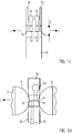
- Fig. 1a shows schematically a first embodiment of a closure module 1 according to the present invention.
- the locking module 1 is used for locking or locking and separating filled sausage casings 5 connected via a sausage plait.
- Such electrically conductive sausage casings can be, for example, a natural casing stored in salt water or an artificial or collagen casing.
- the sausage casing is filled beforehand with a paste, for example sausage meat, for example by means of a filling machine, for example a vacuum filling machine.
- a filling machine for example a vacuum filling machine.
- the tips 6 of the filled sausage casings 5 are connected via the sausage plait 4.
- the connected sausage chains made up of several connected portions are then closed by the closing module 1, for example, in such a way that the filled sausage casings cannot open again, for example during the cutting process with the aid of a knife.
- the closure module 1 it is also possible to use the closure module 1 to close the filled sausage casings 5 with the closure module 1 and to sever the sausage plait. Closing at the end of a sausage chain is also possible.
- the closure module 1 comprises two electrodes 2a, 2b which are arranged here next to one another in the longitudinal direction L of the stretched sausage plait, ie in the direction of the stretched sausage plait.
- the two electrodes have, for example, a distance b in a range from 0.5 mm to 3 mm from one another.
- the longitudinal direction L also corresponds to the longitudinal direction L of the closure element.
- the two electrodes 2a, 2b are integrated here in a stamp 3a made of insulating material.
- the closure module has a further stamp 3b which, like Fig. 1a shows, in the closed state opposite to the stamp element 3a, wherein the sausage plait 4 can be placed between the stamps 3a, 3b.
- the sausage plait 4 can be clamped.
- the two punches 3a, 3b can be moved towards each other until they stop.
- a clamping point K which clamps the sausage plait 4.
- the face of the electrodes is part of the clamping surface.
- a clamping point K1, K2 is implemented at least on the respective side of the electrodes 2a, 2b facing the tip 6. This clamping is advantageous because mechanical tensions arise on the sausage casing at the sausage tip 6 due to the, for example, twisted off compartment and displacement of the sausage mass. If a current is now introduced at the sausage tip 6, the sausage casing 5, which is under mechanical tension, can tear when heated.
- the mechanical stresses are "held".
- a current is generated between the clamping points K1, K2 within the sausage plait 4 or of the open sausage end and thus does not flow over the sausage tips under mechanical tension, but from the first electrode into the sausage plait, over the distance b in the longitudinal direction L through the sausage plait into the second electrode 2b.
- the width c of the stamps 3a, 3b is essentially smaller than the length of the sausage plait 4 so that the stamps with the integrated electrodes can be placed between the sausage portions and is, for example, in a range of 3 mm-10 mm.
- the electrodes 2a, 2b can be cast in the insulating material of the stamp.
- Figure 1b corresponds to in Fig. 1a shown embodiment, but here a stamp 3a is formed in two parts, ie that the respective electrodes 2a, 2b are either poured into their own stamp elements 3a 1 and 3a 2 made of insulating material, or are correspondingly coated with a coating of insulating material. The coating of the electrodes can then, as in the case of FIG Fig. 1a The embodiment shown must be removed at the contact points 20 so that an electric current can flow between the electrodes 2a, 2b. Due to the coating or the insulating material, the two stamp elements 3a 1 , 3a 2 can be connected to one another, for example by screws.
- Figure 1c is a further embodiment of the present invention and corresponds essentially to that in FIG Figures 1a and 1b shown embodiment, wherein here, for example, the upper punch 3a from two separate electrodes 2a, 2b laterally spaced apart in the longitudinal direction L and separate punch elements 3a 1 and 3a 2 are formed.
- the individual elements can for example be attached to a common holder (not shown) and together form the stamp.
- the electrodes 2a and 2b can also have insulation apart from the contact area 20.
- the punch elements 3a 1 , 3a 2 serve to produce the clamping points K1 and K2 together with the lower punch 3b.
- the end faces of the electrodes 2a, 2b also preferably lie in the same plane as the end faces of the stamp elements 3a 1 , 3a 2 , so that the sausage plait 4 is also clamped by the electrodes 2a, 2b.
- the electrodes do not necessarily have to clamp the sausage plait 4, but it is essential that, when the stamp is closed, the distance between the end face of the electrodes and the opposing stamp is so small that the end faces of the electrodes Can touch sausage braid, which serves as an electrolyte.
- Fig. 1d shows a further embodiment of a closure module according to the invention, but with the electrodes in respective punches 3a, 3b on opposite sides of the Sausage plait 4 are integrated.
- the stamps 3a, 3b can be brought up to the stop in such a way that the sausage plait 4 lies between them.
- a current can initially flow in the longitudinal direction L through the sausage casing via an electrode 2a and then flow away through the electrode 2b.
- FIG. 12 shows a further embodiment according to the present invention, the electrodes 2a, 2b also being arranged on opposite sides in the movable punches 3a, 3b, but not as in FIG Fig. 1d laterally, ie, viewed in the longitudinal direction, are spaced apart from one another, but are opposite one another.
- current can flow perpendicularly from electrode 2a through sausage plait 4 to electrode 2b.
- the punches 3a, 3b can only be moved towards one another so far that there can be no short circuit between the electrodes 2a, 2b.
- a minimum distance of 0.1 mm is necessary between the electrodes.
- Figures 2 to 7 show a preferred exemplary embodiment according to the present invention, the closure module 1 being designed as a hand module, in particular as hand pliers.
- the closure module comprises a grip area 7 with two grip elements 7a, 7b which are movable relative to one another and which extend perpendicular to the longitudinal direction L.
- the upper elongated grip element 7a is coupled to the lower punch 3b, which, for example, does not include an electrode in this exemplary embodiment and only serves as an anvil.
- the lower grip element 7b is coupled to the stamp 3a, which comprises two electrodes 2a, 2b.
- the grip elements 7a, 7b are rotatably mounted about the axis A1.
- the punches 3a, 3b also move towards one another - up to a closed position, as in FIG Fig. 4 is shown.
- the grip elements 7a, 7b can be biased into an open position by a spring.
- this embodiment has two electrodes 2a, 2b, which are arranged in the upper punch 3a.
- the upper punch 3a is composed of two punch elements 3a 1 and 3a 2 , as previously in connection with FIG Figure 1b was explained.
- the stamp elements 3 a 1 and 3 a 2 have the internal electrodes 2 a and 2 b, which are exposed at the contact areas 20.
- the two stamp elements 3a 1 , 3a 2 are connected to one another, their outer surfaces essentially tapering towards one another in such a way that the stamp 3a can easily be inserted between the sausages.
- the lower punch 3b also runs essentially conically towards the front.
- the electrodes 2a, 2b are connected to the electrode connections 22a, 22b and are supplied with power via these connections, the power supply being able to take place via a cable (not shown).
- the lower punch 3b is mounted rotatably about the axis A2, here preferably mounted freely rotatable.
- the stamp element 3a can also be mounted rotatably, in particular freely rotatable, about the axis A3.
- the axes A2, A3 run essentially along the longitudinal direction L, i.e. along a direction which corresponds to the stretched sausage plait 4 or essentially perpendicular to a direction of the longitudinal axis of the grip elements 7a, 7b. It can thus be made possible that the opposite clamping surfaces run essentially parallel to one another in order to achieve an optimal clamping effect.
- the upper and / or lower punch (preferably the upper punch) to be mounted freely rotatable about a respective axis A4, which e.g. extends in one direction, essentially perpendicular to the axes A1, A3 or the longitudinal axis of the closure module in order to compensate for tolerances and to ensure that the end faces of the stamps are correctly aligned and parallel to one another.
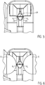
- Fig. 5 shows a front view of the closure module 1, wherein in this embodiment, for example, a recess 24 can be provided between the clamping surfaces or points K1, K2. It is essential that the clamping point K1 is arranged between the electrode 2a and the sausage tip 6 and and the clamping point K2 between the electrodes 2b and the opposite sausage tip 6, as shown in particular in FIG Fig. 6 emerges.
- the clamping point of the sausage plait 4 is as shown Fig. 6 shows, in front of the left sausage tip 6 and the clamping point K2 is in front of the right sausage tip.
- this exemplary embodiment optionally comprises a hook-shaped bracket 21, which is arranged on the end facing away from the grip area 7 and surrounds the end in a bracket-shaped manner.
- This bracket 21 thus serves as protection against damage.
- the bracket has in particular, for example, two sections 21a and 21b tapering to a point S.
- an opening 27 can be seen in a lateral area, so that the bracket 21 can be used as a hook ZB for positioning the module when not in use.
- the hook-shaped bracket does not necessarily have to taper to a point, but can of course also have a different shape, for example rounded.
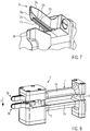
- the hand-held device is not limited to a forceps shape, but can also, for example, in FIG Fig. 8 is shown, be designed as a hand module, in which the stamps 3a, 3b to move towards one another when the grip elements 7, 7b are moved towards one another.
- a column guide 9 can be provided for this purpose, for example.
- a voltage can be applied to the electrodes 2a, 2b in the closed position for closing and separating.
- the voltage supply can either be started automatically via a position switch, for example, when the locking module is in a closed position (for example, on the stop) or it can be triggered manually via a switch (not shown).
- This can be a switch on the device or, for example, a foot switch.
- the voltage is supplied automatically.
- a measuring potential is applied between the two electrodes.
- the resistance between the electrodes can be measured and, depending on the resistance, it can be determined whether there is a sausage casing between the electrodes. If it is determined that there is a sausage plait in the closure module between the electrodes, the voltage and / or the current and thus the power for the closure are automatically increased, in particular after an adjustable time.
- the sausage plait then serves as the electrolyte between the electrodes 2a, 2b.
- the closure module 1 is first placed, for example, between two filled sausage casings 5 or at an open sausage end (not shown), for example in FIG Fig. 6 is shown.
- the locking module 1 is in an open position, for example in Fig. 2 shown.
- the opposing punches 3a, 3b are then introduced in an area between filled sausage casings 5 such that the sausage plait 4 is placed between the punches 3a, 3a, as for example in FIG Fig. 6 or Figures 1a to 1e is shown.
- the stamps For closing or closing and separating, the stamps must now be moved relative to one another, as shown by the arrow P in the figures.
- an operator can use the locking module like gripping pliers and encompass the grip area 7 and move the grip elements 7a, 7b towards one another.
- the punches 3a, 3b also move towards one another until they reach an end position in which there are at least the previously explained clamping points K1, K2 that clamp the sausage plait.
- the electrodes 2a, 2b are now over the electrically conductive sausage braid 4, regardless of their configuration according to FIG Fig. 1a to e conductively connected to each other. Via a position switch or manual actuation of a corresponding switch, current can then flow from a power source (not shown) via cables, also not shown, via the electrode connection and the electrode 2a into the sausage plait 4 and from there into the further electrode 2b.
- Particularly advantageous flows such as in Fig. 1a shown, or from Fig.
- High-frequency currents in a frequency range from 300 kHz to 500 kHz have proven particularly suitable.
- the voltage is advantageously in a range from 50 to 500 V, in particular 80 to 430 V.
- the electrical energy is converted into thermal energy and heats the sausage plait, e.g. to temperatures of 60 to 350 ° C. In this temperature range e.g. the thermal denaturation of collagen, which can be recognized by a whitish discoloration.
- the power for sealing should therefore be in a range from 40 W to 150 W, preferably between 50 W and 100 W, for example.
- a certain amount of energy is released per time during a first time interval t 1 in such a way that the sausage plait is heated and closes, especially coagulates. If the sausage plait 4 is now also to be severed, an increase in output, in particular a peak-like increase in output, can take place during a second time interval t 2 , which leads to a rapid cutting process.
- the power supply is then ended either manually or automatically, for example after a predetermined time or by triggering a switch or position switch.
- the punches 3a, 3b can then be moved apart again counter to the direction of the arrow P, so that, as from Fig. 2 emerges, again results in a distance between the stamps 3a, 3b and the module can be removed.
- the punches 3a, 3b can also be moved towards or apart from one another by an actuator, in particular a pneumatic or electric actuator.
Landscapes
- Engineering & Computer Science (AREA)
- Life Sciences & Earth Sciences (AREA)
- Mechanical Engineering (AREA)
- Wood Science & Technology (AREA)
- Zoology (AREA)
- Food Science & Technology (AREA)
- Meat, Egg Or Seafood Products (AREA)
Claims (16)
- Module de fermeture (1) pour fermer et/ou séparer les enveloppes de saucisse remplies (5) et reliées par une tresse de chair à saucisse (4), comprenant
deux poinçons (3a, 3b) mobiles l'un par rapport à l'autre et disposés de manière à pouvoir être séparés par une tresse de chair à saucisse (4), qui peuvent serrer la tresse de chair à saucisse une fois refermée et sont pourvus
d'une première électrode et d'une seconde électrode (2a, b), à travers lesquelles, lorsque les poinçons (3a, 3b) sont fermés, un courant peut circuler de la première électrode (2a) dans la tresse de chair à saucisse (4) et à travers la tresse de chair à saucisse (4) dans la seconde électrode (2b), l'énergie électrique étant convertie en énergie thermique lorsqu'elle circule à travers la tresse de chair à saucisse et chauffe la tresse de chair à saucisse, les enveloppes de saucisse remplies, lorsqu'elles sont fermées, de préférence séparées, dans lequel
le module de fermeture est conçu comme un dispositif portable à la main, avec une zone de préhension (7) comprenant deux éléments de préhension (7a, b) espacés l'un de l'autre et opposés, qui peuvent être déplacés l'un par rapport à l'autre et sont chacun couplés aux poinçons (3a, 3b) de telle sorte que lorsque les éléments de préhension (7a, 7b) sont déplacés l'un vers l'autre, les électrodes et les poinçons respectifs se déplacent également l'un vers l'autre. - Module de fermeture (1) selon la revendication 1, caractérisé en ce que les électrodes (2a, 2b) sont disposées de telle sorte que, lorsque les poinçons (3a, 3b) sont fermés, elles sont espacées des crosses de saucisse (6) des enveloppes de saucisse (5) de telle sorte que les électrodes (2a, 2b) ne touchent pas les enveloppes de saucisse remplies, un matériau isolant étant notamment prévu sur les côtés des électrodes orientés vers l'extérieur.
- Module de fermeture selon les revendications 1 ou 2, caractérisé en ce que un point de serrage (K1, K2) des poinçons (3a, 3b) est disposé au moins sur le côté respectif des électrodes (2a, 2b) tourné vers la crosse (6) de la tresse de chair à saucisse et de préférence
les deux électrodes (2a, 2b) sont disposées dans l'un des poinçons (3a) à distance l'une de l'autre ou
la première électrode (2a) est disposée dans l'un des poinçons (3a) et la seconde électrode (2b) dans le poinçon opposé (3b), les électrodes étant de préférence disposées de manière décalée latéralement l'une par rapport à l'autre sur les côtés opposés de la tresse de chair à saucisse. - Module d'étanchéité selon au moins l'une des revendications 1 à 3, caractérisé en ce que les électrodes (2a, 2b) dans le poinçon (3a, 3b) sont isolées de l'extérieur et une zone de contact libre (20) est prévue seulement à leur extrémité tournée vers la tresse de chair à saucisse, le poinçon (3a, 3b) étant en particulier formé d'une seule pièce ou chaque électrode (2a, 2b) étant disposée dans son propre élément de poinçon.
- Module de fermeture selon au moins la revendication 3, caractérisé en ce que les électrodes (2a, 2b) ont un revêtement isolant ou sont coulées dans les mêmes dimensions, la surface de contact (20) des électrodes (2a, 2b) étant laissée de côté.
- Module de fermeture selon au moins l'une des revendications 1 à 5, caractérisé en ce que la distance entre les électrodes (2a, 2b) disposées l'une à côté de l'autre se situe dans une plage de 0,5 mm à 3 mm.
- Module de fermeture selon au moins l'une des revendications 1 à 6, en ce qu'au moins l'un des poinçons opposés (3a, 3b) est monté de manière à pouvoir tourner autour d'un axe A2, A3, qui s'étend dans une direction longitudinale L, en particulier est monté de manière à pouvoir tourner librement, de telle sorte que les surfaces de serrage opposées (K1, K2) s'étendent essentiellement parallèlement l'une à l'autre.
- Module de fermeture selon au moins l'une des revendications 1 à 8, caractérisé en ce que les électrodes et les poinçons peuvent être déplacés les uns par rapport aux autres manuellement ou au moyen d'un actionneur, en particulier un actionneur pneumatique ou électrique.
- Module de fermeture selon au moins l'une des revendications 1 à 7, caractérisé en ce que l'outil à main est conçu comme une paire de pinces à main dont les éléments de poignée sont montés de manière à pouvoir tourner.
- Module de fermeture selon la revendication 9, caractérisé en ce que le module de fermeture présente à son extrémité opposée à la zone de préhension (7) une pince en forme de crochet (21), laquelle pince présente en particulier deux sections (21a, 21b) s'effilant vers une pointe (S).
- Procédé de fermeture et/ou de séparation de enveloppes de saucisse remplies (5) et reliées par une tresse de chair à saucisse (4) à un module de fermeture (1) selon la revendication 1 avec les étapes suivantes :placer une tresse de chair à saucisse (4) entre un premier poinçon (3a) et un second poinçon (3b),rapprocher les poinçons l'un de l'autre de manière à ce que les poinçons (3a, 3b) soient fermés et enserrent la tresse de la saucisse (4),après quoi, faire circuler un courant de la première électrode dans la tresse de chair à saucisse (4) et, à travers la tresse de chair à saucisse, dans la seconde électrode (2a), l'énergie électrique étant transformée en énergie thermique lors de son passage dans la tresse de chair à saucisse et chauffant la tresse de chair à saucisse, l'enveloppe de la saucisse remplie étant scellée, de préférence encore séparée, dans lequel le module de fermeture est conçu comme dispositif portable à la main, avec une zone de préhension (7) comprenant deux éléments de préhension (7a, 7b) espacés l'un de l'autre et opposés, qui peuvent être déplacés l'un par rapport à l'autre et sont chacun couplés aux poinçons (3a, 3b) de telle sorte que lorsque les éléments de préhension (7a, 7b) sont déplacés l'un vers l'autre, les électrodes et les poinçons respectifs se déplacent également l'un vers l'autre.
- Procédé selon la revendication 11, caractérisé en ce que la tresse de chair à saucisse (4) est enserré par les poinçons (3a, 3b) au moins sur le côté des électrodes (2a, 2b) tourné vers la crosse de saucisse respective.
- Procédé selon au moins une des revendications 11 ou 12, caractérisé en ce qu'une quantité d'énergie est émise par temps par l'intermédiaire des électrodes (2a, 2b) pendant une première période de temps t1 de telle sorte que la tête de saucisse (4) est chauffée et scellée et en particulier pendant une seconde période t2, de l'énergie supplémentaire est fournie, la quantité d'énergie par temps étant de préférence augmentée, en particulier sous forme de pic, de telle sorte que la tresse de chair à saucisse (4) soit décomposée et séparée.
- Procédé selon au moins l'une des revendications 11 à 13, caractérisé en ce que le courant est un courant à haute fréquence, en particulier dans une gamme de fréquences de 300 kHz à 500 kHz.
- Procédé selon au moins une des revendications 11 à 14, caractérisé en ce qu'une tension dans une plage de 50-500 V, en particulier 80-430 V, est appliquée aux électrodes (2a, 2b).
- Procédé selon au moins une des revendications 11 à 15, caractérisé en ce que le serrage de la tête de saucisse (4) n'est libéré que lorsque plus aucun courant ne passe par les électrodes (2a, 2b).
Priority Applications (6)
| Application Number | Priority Date | Filing Date | Title |
|---|---|---|---|
| PL18181189T PL3590344T3 (pl) | 2018-07-02 | 2018-07-02 | Moduł zamykający i sposób zamykania i/lub oddzielania wypełnionych osłonek kiełbasianych połączonych warkoczem kiełbasianym |
| ES18181189T ES2822203T3 (es) | 2018-07-02 | 2018-07-02 | Módulo de cierre y procedimiento para cerrar y/o separar tripas para embutido rellenas unidas a través de una ristra de embutidos |
| EP18181189.4A EP3590344B1 (fr) | 2018-07-02 | 2018-07-02 | Module de fermeture et procédé de fermeture et/ou de séparation des enveloppes de saucisse remplies reliées à l'aide d'une tresse de chair à saucisse |
| JP2019114872A JP6835388B2 (ja) | 2018-07-02 | 2019-06-20 | ソーセージ首部を介して連結された充填済みソーセージケーシングを閉鎖及び/又は分離するための閉鎖モジュール及び方法 |
| CN201910585784.1A CN110663750B (zh) | 2018-07-02 | 2019-07-01 | 用于封闭和/或分离填充的香肠肠衣的封闭模块和方法 |
| US16/460,654 US11528915B2 (en) | 2018-07-02 | 2019-07-02 | Closure module and method for closing and/or separating filled sausage casings connected via a sausage neck |
Applications Claiming Priority (1)
| Application Number | Priority Date | Filing Date | Title |
|---|---|---|---|
| EP18181189.4A EP3590344B1 (fr) | 2018-07-02 | 2018-07-02 | Module de fermeture et procédé de fermeture et/ou de séparation des enveloppes de saucisse remplies reliées à l'aide d'une tresse de chair à saucisse |
Publications (2)
| Publication Number | Publication Date |
|---|---|
| EP3590344A1 EP3590344A1 (fr) | 2020-01-08 |
| EP3590344B1 true EP3590344B1 (fr) | 2020-09-16 |
Family
ID=62845987
Family Applications (1)
| Application Number | Title | Priority Date | Filing Date |
|---|---|---|---|
| EP18181189.4A Active EP3590344B1 (fr) | 2018-07-02 | 2018-07-02 | Module de fermeture et procédé de fermeture et/ou de séparation des enveloppes de saucisse remplies reliées à l'aide d'une tresse de chair à saucisse |
Country Status (6)
| Country | Link |
|---|---|
| US (1) | US11528915B2 (fr) |
| EP (1) | EP3590344B1 (fr) |
| JP (1) | JP6835388B2 (fr) |
| CN (1) | CN110663750B (fr) |
| ES (1) | ES2822203T3 (fr) |
| PL (1) | PL3590344T3 (fr) |
Citations (1)
| Publication number | Priority date | Publication date | Assignee | Title |
|---|---|---|---|---|
| US20040211156A1 (en) * | 2003-04-24 | 2004-10-28 | Frans Vermee Gmbh | Method and device for manufacturing tubular packs filled with a material as well as tubular pack filled with a material |
Family Cites Families (19)
| Publication number | Priority date | Publication date | Assignee | Title |
|---|---|---|---|---|
| AT178854B (de) * | 1948-11-19 | 1954-06-25 | Leopold Rado | Maschine zur Herstellung von mit Flüssigkeiten oder Pasten gefüllten Behältern |
| GB716783A (en) * | 1950-04-05 | 1954-10-13 | Leopold Rado | Improvements in packaging machines |
| DE1080011B (de) * | 1957-07-25 | 1960-04-14 | Ludwig Kannengiesser | Verfahren und Vorrichtung zur Herstellung von Einzelpackungen aus schlauchfoermigem Packmaterial |
| US3382641A (en) * | 1965-09-17 | 1968-05-14 | Kartridg Pak Co | Continuous tube packaging machine |
| GB1232801A (fr) * | 1968-06-18 | 1971-05-19 | ||
| US3992606A (en) | 1975-09-18 | 1976-11-16 | Cosmos Electronic Machine Corporation | Portable heat sealer |
| DE3726703A1 (de) * | 1987-08-11 | 1989-02-23 | Josef Lemmer | Vorsatzgeraet fuer einen wurstfueller |
| JPH01310893A (ja) * | 1988-06-09 | 1989-12-14 | Prima Meat Packers Ltd | ウインナー・ソーセージ切断装置 |
| DE9212976U1 (de) | 1992-09-28 | 1994-02-03 | Vemag Maschinenbau GmbH, 27283 Verden | Vorrichtung zum Verschließen von Wurstenden u.dgl. |
| CN2333193Y (zh) * | 1998-05-26 | 1999-08-18 | 张文迅 | 模块式多功能饺子机 |
| CN2349133Y (zh) * | 1998-09-25 | 1999-11-17 | 衡水鸿昊企业有限责任公司 | 卡扣封口机 |
| CN2427973Y (zh) * | 2000-06-19 | 2001-05-02 | 关多友 | 包馅机 |
| JP2002331586A (ja) * | 2001-05-08 | 2002-11-19 | Yamamoto Vinita Co Ltd | 高周波ハンドウェルダー |
| KR20040017104A (ko) * | 2002-08-20 | 2004-02-26 | 서치영 | 저전력 핸디 전열씰러 |
| JP3957193B2 (ja) * | 2002-12-27 | 2007-08-15 | プリマハム株式会社 | 連鎖状ソーセージの繋ぎ部溶断装置 |
| DE102004024129B4 (de) * | 2004-05-14 | 2009-02-26 | Poly-Clip System Gmbh & Co Kg | Etikettenspender |
| EP1609366B1 (fr) | 2004-06-25 | 2007-05-16 | Prima Meat Packers, Ltd. | Dispositif et méthode pour couper des saucisses d'un chapelet de saucisses |
| JP3986075B2 (ja) * | 2004-06-28 | 2007-10-03 | プリマハム株式会社 | ソーセージの製造システム |
| CN204206986U (zh) * | 2014-05-26 | 2015-03-18 | 兰溪健发食品机械有限公司 | 一种圈状面包面坯的自动成型装置 |
-
2018
- 2018-07-02 EP EP18181189.4A patent/EP3590344B1/fr active Active
- 2018-07-02 ES ES18181189T patent/ES2822203T3/es active Active
- 2018-07-02 PL PL18181189T patent/PL3590344T3/pl unknown
-
2019
- 2019-06-20 JP JP2019114872A patent/JP6835388B2/ja active Active
- 2019-07-01 CN CN201910585784.1A patent/CN110663750B/zh active Active
- 2019-07-02 US US16/460,654 patent/US11528915B2/en active Active
Patent Citations (1)
| Publication number | Priority date | Publication date | Assignee | Title |
|---|---|---|---|---|
| US20040211156A1 (en) * | 2003-04-24 | 2004-10-28 | Frans Vermee Gmbh | Method and device for manufacturing tubular packs filled with a material as well as tubular pack filled with a material |
Also Published As
| Publication number | Publication date |
|---|---|
| PL3590344T3 (pl) | 2021-03-08 |
| ES2822203T3 (es) | 2021-04-29 |
| JP2020005636A (ja) | 2020-01-16 |
| US20200000108A1 (en) | 2020-01-02 |
| CN110663750B (zh) | 2022-01-04 |
| CN110663750A (zh) | 2020-01-10 |
| JP6835388B2 (ja) | 2021-02-24 |
| US11528915B2 (en) | 2022-12-20 |
| EP3590344A1 (fr) | 2020-01-08 |
Similar Documents
| Publication | Publication Date | Title |
|---|---|---|
| DE69232781T2 (de) | Elektrochirurgisches schneidwerkzeug | |
| EP1336384B1 (fr) | Instrument medical bipolaire pour couper des tissues | |
| DE102016100588B4 (de) | Elektrochirurgisches Instrument mit elektrisch leitfähigen Anschlagelementen und Verfahren zur Herstellung eines Backenelements für ein elektrochirurgisches Instrument | |
| DE60312873T2 (de) | Elektrochirurgisches instrument zum verschluss von gefässen | |
| EP3097870B1 (fr) | Systeme chirurgical destine a relier des tissus corporels | |
| EP2512358B1 (fr) | Système chirurgical et procédé de commande pour instrument chirurgical pour relier des parties tissulaires corporelles | |
| DE1590061A1 (de) | Maschine zum Entfernen der Isolation elektrischer Draehte | |
| EP1107703A1 (fr) | Instrument medical bipolaire servant a couper des tissus | |
| WO2009059741A1 (fr) | Appareil chirurgical pour sceller des vaisseaux sanguins et adhésif thermodurcissable servant d'agent pharmaceutique | |
| DE3922437A1 (de) | Drahtbearbeitungsvorrichtung | |
| DE102009059195A1 (de) | Chirurgisches System zum Verbinden von Körpergewebe und Verfahren zum Abtrennen überstehenden Gewebes | |
| EP2679186A1 (fr) | Instrument de fusion et de séparation des tissus | |
| EP3334351A1 (fr) | Dispositif de coupe de pièces de tissu | |
| DE102015112320B3 (de) | Vorrichtung und Verfahren zum Abisolieren von Leitungen oder Kabeln | |
| DE102017126800A1 (de) | Verfahren zur Behandlung eines Lebensmittels, welches sich in einer isolierenden Kapselung oder Umhüllung befindet oder dort eingebracht wird mittels nicht-konventioneller, Ohm'scher Erhitzung | |
| DE3013824A1 (de) | Vorrichtung und verfahren zum zerschneiden und verschweissen von polymerisatfolien | |
| EP3590344B1 (fr) | Module de fermeture et procédé de fermeture et/ou de séparation des enveloppes de saucisse remplies reliées à l'aide d'une tresse de chair à saucisse | |
| DE68913232T2 (de) | Apparat und Verfahren zum Entfernen eines Isolierungsstückes entlang der Länge eines isolierten Drahtes. | |
| EP3590345B1 (fr) | Module de fermeture et procédé de fermeture et/ou de séparation des enveloppes de saucisse remplies reliées à l'aide d'une tresse de chair à saucisse | |
| DE2346291C3 (de) | Verfahren und Vorrichtung zur Herstellung einer elektrischen Verbindung zwischen zwei oder mehreren Leiterdrähten | |
| WO1994007371A1 (fr) | Procede et dispositif pour fermer les extremites de saucisses ou analogues | |
| DE69513046T2 (de) | Gerät zur herstellung von kabelbäumen | |
| DE102011055008B4 (de) | Vorrichtung zum Verschließen und Abtrennen von Würsten aus einem Wurststrang sowie Verfahren zum Verschließen und Abtrennen von Würsten aus einem Wurststrang | |
| DE69203175T2 (de) | Verfahren für die Herstellung von Leitungslitzen für die elektromechanische Gerätetechnik und Vorrichtung für die Ausführung des Verfahrens. | |
| EP2018808B1 (fr) | Dispositif et procédé destinés à raccourcir des boyaux remplis de matériau de remplissage |
Legal Events
| Date | Code | Title | Description |
|---|---|---|---|
| STAA | Information on the status of an ep patent application or granted ep patent |
Free format text: STATUS: EXAMINATION IS IN PROGRESS |
|
| PUAI | Public reference made under article 153(3) epc to a published international application that has entered the european phase |
Free format text: ORIGINAL CODE: 0009012 |
|
| REG | Reference to a national code |
Ref country code: DE Ref legal event code: R079 Ref document number: 502018002454 Country of ref document: DE Free format text: PREVIOUS MAIN CLASS: A22C0011000000 Ipc: B65B0051220000 |
|
| 17P | Request for examination filed |
Effective date: 20190222 |
|
| AK | Designated contracting states |
Kind code of ref document: A1 Designated state(s): AL AT BE BG CH CY CZ DE DK EE ES FI FR GB GR HR HU IE IS IT LI LT LU LV MC MK MT NL NO PL PT RO RS SE SI SK SM TR |
|
| AX | Request for extension of the european patent |
Extension state: BA ME |
|
| GRAP | Despatch of communication of intention to grant a patent |
Free format text: ORIGINAL CODE: EPIDOSNIGR1 |
|
| STAA | Information on the status of an ep patent application or granted ep patent |
Free format text: STATUS: GRANT OF PATENT IS INTENDED |
|
| RIC1 | Information provided on ipc code assigned before grant |
Ipc: A22C 11/00 20060101ALI20200106BHEP Ipc: B65B 51/22 20060101AFI20200106BHEP Ipc: A22C 11/10 20060101ALI20200106BHEP Ipc: B65B 51/30 20060101ALI20200106BHEP Ipc: A22C 11/12 20060101ALI20200106BHEP |
|
| INTG | Intention to grant announced |
Effective date: 20200203 |
|
| GRAS | Grant fee paid |
Free format text: ORIGINAL CODE: EPIDOSNIGR3 |
|
| GRAA | (expected) grant |
Free format text: ORIGINAL CODE: 0009210 |
|
| STAA | Information on the status of an ep patent application or granted ep patent |
Free format text: STATUS: THE PATENT HAS BEEN GRANTED |
|
| AK | Designated contracting states |
Kind code of ref document: B1 Designated state(s): AL AT BE BG CH CY CZ DE DK EE ES FI FR GB GR HR HU IE IS IT LI LT LU LV MC MK MT NL NO PL PT RO RS SE SI SK SM TR |
|
| REG | Reference to a national code |
Ref country code: GB Ref legal event code: FG4D Free format text: NOT ENGLISH |
|
| REG | Reference to a national code |
Ref country code: CH Ref legal event code: EP Ref country code: CH Ref legal event code: NV Representative=s name: BOVARD AG PATENT- UND MARKENANWAELTE, CH |
|
| REG | Reference to a national code |
Ref country code: DE Ref legal event code: R096 Ref document number: 502018002454 Country of ref document: DE |
|
| REG | Reference to a national code |
Ref country code: IE Ref legal event code: FG4D Free format text: LANGUAGE OF EP DOCUMENT: GERMAN |
|
| REG | Reference to a national code |
Ref country code: AT Ref legal event code: REF Ref document number: 1313978 Country of ref document: AT Kind code of ref document: T Effective date: 20201015 |
|
| REG | Reference to a national code |
Ref country code: NL Ref legal event code: FP |
|
| PG25 | Lapsed in a contracting state [announced via postgrant information from national office to epo] |
Ref country code: BG Free format text: LAPSE BECAUSE OF FAILURE TO SUBMIT A TRANSLATION OF THE DESCRIPTION OR TO PAY THE FEE WITHIN THE PRESCRIBED TIME-LIMIT Effective date: 20201216 Ref country code: HR Free format text: LAPSE BECAUSE OF FAILURE TO SUBMIT A TRANSLATION OF THE DESCRIPTION OR TO PAY THE FEE WITHIN THE PRESCRIBED TIME-LIMIT Effective date: 20200916 Ref country code: GR Free format text: LAPSE BECAUSE OF FAILURE TO SUBMIT A TRANSLATION OF THE DESCRIPTION OR TO PAY THE FEE WITHIN THE PRESCRIBED TIME-LIMIT Effective date: 20201217 Ref country code: NO Free format text: LAPSE BECAUSE OF FAILURE TO SUBMIT A TRANSLATION OF THE DESCRIPTION OR TO PAY THE FEE WITHIN THE PRESCRIBED TIME-LIMIT Effective date: 20201216 Ref country code: FI Free format text: LAPSE BECAUSE OF FAILURE TO SUBMIT A TRANSLATION OF THE DESCRIPTION OR TO PAY THE FEE WITHIN THE PRESCRIBED TIME-LIMIT Effective date: 20200916 Ref country code: SE Free format text: LAPSE BECAUSE OF FAILURE TO SUBMIT A TRANSLATION OF THE DESCRIPTION OR TO PAY THE FEE WITHIN THE PRESCRIBED TIME-LIMIT Effective date: 20200916 |
|
| PG25 | Lapsed in a contracting state [announced via postgrant information from national office to epo] |
Ref country code: RS Free format text: LAPSE BECAUSE OF FAILURE TO SUBMIT A TRANSLATION OF THE DESCRIPTION OR TO PAY THE FEE WITHIN THE PRESCRIBED TIME-LIMIT Effective date: 20200916 Ref country code: LV Free format text: LAPSE BECAUSE OF FAILURE TO SUBMIT A TRANSLATION OF THE DESCRIPTION OR TO PAY THE FEE WITHIN THE PRESCRIBED TIME-LIMIT Effective date: 20200916 |
|
| REG | Reference to a national code |
Ref country code: LT Ref legal event code: MG4D |
|
| PG25 | Lapsed in a contracting state [announced via postgrant information from national office to epo] |
Ref country code: EE Free format text: LAPSE BECAUSE OF FAILURE TO SUBMIT A TRANSLATION OF THE DESCRIPTION OR TO PAY THE FEE WITHIN THE PRESCRIBED TIME-LIMIT Effective date: 20200916 Ref country code: PT Free format text: LAPSE BECAUSE OF FAILURE TO SUBMIT A TRANSLATION OF THE DESCRIPTION OR TO PAY THE FEE WITHIN THE PRESCRIBED TIME-LIMIT Effective date: 20210118 Ref country code: RO Free format text: LAPSE BECAUSE OF FAILURE TO SUBMIT A TRANSLATION OF THE DESCRIPTION OR TO PAY THE FEE WITHIN THE PRESCRIBED TIME-LIMIT Effective date: 20200916 Ref country code: CZ Free format text: LAPSE BECAUSE OF FAILURE TO SUBMIT A TRANSLATION OF THE DESCRIPTION OR TO PAY THE FEE WITHIN THE PRESCRIBED TIME-LIMIT Effective date: 20200916 Ref country code: LT Free format text: LAPSE BECAUSE OF FAILURE TO SUBMIT A TRANSLATION OF THE DESCRIPTION OR TO PAY THE FEE WITHIN THE PRESCRIBED TIME-LIMIT Effective date: 20200916 Ref country code: SM Free format text: LAPSE BECAUSE OF FAILURE TO SUBMIT A TRANSLATION OF THE DESCRIPTION OR TO PAY THE FEE WITHIN THE PRESCRIBED TIME-LIMIT Effective date: 20200916 |
|
| PG25 | Lapsed in a contracting state [announced via postgrant information from national office to epo] |
Ref country code: IS Free format text: LAPSE BECAUSE OF FAILURE TO SUBMIT A TRANSLATION OF THE DESCRIPTION OR TO PAY THE FEE WITHIN THE PRESCRIBED TIME-LIMIT Effective date: 20210116 Ref country code: AL Free format text: LAPSE BECAUSE OF FAILURE TO SUBMIT A TRANSLATION OF THE DESCRIPTION OR TO PAY THE FEE WITHIN THE PRESCRIBED TIME-LIMIT Effective date: 20200916 |
|
| REG | Reference to a national code |
Ref country code: DE Ref legal event code: R097 Ref document number: 502018002454 Country of ref document: DE |
|
| PG25 | Lapsed in a contracting state [announced via postgrant information from national office to epo] |
Ref country code: SK Free format text: LAPSE BECAUSE OF FAILURE TO SUBMIT A TRANSLATION OF THE DESCRIPTION OR TO PAY THE FEE WITHIN THE PRESCRIBED TIME-LIMIT Effective date: 20200916 |
|
| PLBE | No opposition filed within time limit |
Free format text: ORIGINAL CODE: 0009261 |
|
| STAA | Information on the status of an ep patent application or granted ep patent |
Free format text: STATUS: NO OPPOSITION FILED WITHIN TIME LIMIT |
|
| 26N | No opposition filed |
Effective date: 20210617 |
|
| PG25 | Lapsed in a contracting state [announced via postgrant information from national office to epo] |
Ref country code: DK Free format text: LAPSE BECAUSE OF FAILURE TO SUBMIT A TRANSLATION OF THE DESCRIPTION OR TO PAY THE FEE WITHIN THE PRESCRIBED TIME-LIMIT Effective date: 20200916 |
|
| PG25 | Lapsed in a contracting state [announced via postgrant information from national office to epo] |
Ref country code: MC Free format text: LAPSE BECAUSE OF FAILURE TO SUBMIT A TRANSLATION OF THE DESCRIPTION OR TO PAY THE FEE WITHIN THE PRESCRIBED TIME-LIMIT Effective date: 20200916 |
|
| REG | Reference to a national code |
Ref country code: BE Ref legal event code: MM Effective date: 20210731 |
|
| PG25 | Lapsed in a contracting state [announced via postgrant information from national office to epo] |
Ref country code: LU Free format text: LAPSE BECAUSE OF NON-PAYMENT OF DUE FEES Effective date: 20210702 |
|
| PG25 | Lapsed in a contracting state [announced via postgrant information from national office to epo] |
Ref country code: IE Free format text: LAPSE BECAUSE OF NON-PAYMENT OF DUE FEES Effective date: 20210702 Ref country code: BE Free format text: LAPSE BECAUSE OF NON-PAYMENT OF DUE FEES Effective date: 20210731 |
|
| GBPC | Gb: european patent ceased through non-payment of renewal fee |
Effective date: 20220702 |
|
| PG25 | Lapsed in a contracting state [announced via postgrant information from national office to epo] |
Ref country code: GB Free format text: LAPSE BECAUSE OF NON-PAYMENT OF DUE FEES Effective date: 20220702 |
|
| P01 | Opt-out of the competence of the unified patent court (upc) registered |
Effective date: 20230523 |
|
| PG25 | Lapsed in a contracting state [announced via postgrant information from national office to epo] |
Ref country code: CY Free format text: LAPSE BECAUSE OF FAILURE TO SUBMIT A TRANSLATION OF THE DESCRIPTION OR TO PAY THE FEE WITHIN THE PRESCRIBED TIME-LIMIT Effective date: 20200916 |
|
| PG25 | Lapsed in a contracting state [announced via postgrant information from national office to epo] |
Ref country code: HU Free format text: LAPSE BECAUSE OF FAILURE TO SUBMIT A TRANSLATION OF THE DESCRIPTION OR TO PAY THE FEE WITHIN THE PRESCRIBED TIME-LIMIT; INVALID AB INITIO Effective date: 20180702 |
|
| PG25 | Lapsed in a contracting state [announced via postgrant information from national office to epo] |
Ref country code: SI Free format text: LAPSE BECAUSE OF FAILURE TO SUBMIT A TRANSLATION OF THE DESCRIPTION OR TO PAY THE FEE WITHIN THE PRESCRIBED TIME-LIMIT Effective date: 20200916 |
|
| PG25 | Lapsed in a contracting state [announced via postgrant information from national office to epo] |
Ref country code: MK Free format text: LAPSE BECAUSE OF FAILURE TO SUBMIT A TRANSLATION OF THE DESCRIPTION OR TO PAY THE FEE WITHIN THE PRESCRIBED TIME-LIMIT Effective date: 20200916 |
|
| PG25 | Lapsed in a contracting state [announced via postgrant information from national office to epo] |
Ref country code: MT Free format text: LAPSE BECAUSE OF FAILURE TO SUBMIT A TRANSLATION OF THE DESCRIPTION OR TO PAY THE FEE WITHIN THE PRESCRIBED TIME-LIMIT Effective date: 20200916 |
|
| PGFP | Annual fee paid to national office [announced via postgrant information from national office to epo] |
Ref country code: NL Payment date: 20250724 Year of fee payment: 8 |
|
| PGFP | Annual fee paid to national office [announced via postgrant information from national office to epo] |
Ref country code: ES Payment date: 20250801 Year of fee payment: 8 |
|
| PGFP | Annual fee paid to national office [announced via postgrant information from national office to epo] |
Ref country code: DE Payment date: 20250725 Year of fee payment: 8 |
|
| PGFP | Annual fee paid to national office [announced via postgrant information from national office to epo] |
Ref country code: PL Payment date: 20250701 Year of fee payment: 8 Ref country code: IT Payment date: 20250729 Year of fee payment: 8 |
|
| PGFP | Annual fee paid to national office [announced via postgrant information from national office to epo] |
Ref country code: AT Payment date: 20250721 Year of fee payment: 8 Ref country code: FR Payment date: 20250729 Year of fee payment: 8 |
|
| PGFP | Annual fee paid to national office [announced via postgrant information from national office to epo] |
Ref country code: CH Payment date: 20250801 Year of fee payment: 8 |
|
| PG25 | Lapsed in a contracting state [announced via postgrant information from national office to epo] |
Ref country code: TR Free format text: LAPSE BECAUSE OF FAILURE TO SUBMIT A TRANSLATION OF THE DESCRIPTION OR TO PAY THE FEE WITHIN THE PRESCRIBED TIME-LIMIT Effective date: 20200916 |