EP3590813B1 - Bicyclette pourvue d'un entraînement auxiliaire fonctionnant sur batterie et cadre de bicyclette correspondant - Google Patents
Bicyclette pourvue d'un entraînement auxiliaire fonctionnant sur batterie et cadre de bicyclette correspondant Download PDFInfo
- Publication number
- EP3590813B1 EP3590813B1 EP18181933.5A EP18181933A EP3590813B1 EP 3590813 B1 EP3590813 B1 EP 3590813B1 EP 18181933 A EP18181933 A EP 18181933A EP 3590813 B1 EP3590813 B1 EP 3590813B1
- Authority
- EP
- European Patent Office
- Prior art keywords
- battery
- frame tube
- locking
- bicycle
- optionally
- Prior art date
- Legal status (The legal status is an assumption and is not a legal conclusion. Google has not performed a legal analysis and makes no representation as to the accuracy of the status listed.)
- Active
Links
Images


Classifications
-
- B—PERFORMING OPERATIONS; TRANSPORTING
- B62—LAND VEHICLES FOR TRAVELLING OTHERWISE THAN ON RAILS
- B62M—RIDER PROPULSION OF WHEELED VEHICLES OR SLEDGES; POWERED PROPULSION OF SLEDGES OR SINGLE-TRACK CYCLES; TRANSMISSIONS SPECIALLY ADAPTED FOR SUCH VEHICLES
- B62M6/00—Rider propulsion of wheeled vehicles with additional source of power, e.g. combustion engine or electric motor
- B62M6/80—Accessories, e.g. power sources; Arrangements thereof
- B62M6/90—Batteries
-
- B—PERFORMING OPERATIONS; TRANSPORTING
- B62—LAND VEHICLES FOR TRAVELLING OTHERWISE THAN ON RAILS
- B62J—CYCLE SADDLES OR SEATS; AUXILIARY DEVICES OR ACCESSORIES SPECIALLY ADAPTED TO CYCLES AND NOT OTHERWISE PROVIDED FOR, e.g. ARTICLE CARRIERS OR CYCLE PROTECTORS
- B62J43/00—Arrangements of batteries
- B62J43/10—Arrangements of batteries for propulsion
- B62J43/13—Arrangements of batteries for propulsion on rider-propelled cycles with additional electric propulsion
-
- B—PERFORMING OPERATIONS; TRANSPORTING
- B62—LAND VEHICLES FOR TRAVELLING OTHERWISE THAN ON RAILS
- B62J—CYCLE SADDLES OR SEATS; AUXILIARY DEVICES OR ACCESSORIES SPECIALLY ADAPTED TO CYCLES AND NOT OTHERWISE PROVIDED FOR, e.g. ARTICLE CARRIERS OR CYCLE PROTECTORS
- B62J43/00—Arrangements of batteries
- B62J43/20—Arrangements of batteries characterised by the mounting
- B62J43/28—Arrangements of batteries characterised by the mounting hidden within the cycle frame
-
- B—PERFORMING OPERATIONS; TRANSPORTING
- B62—LAND VEHICLES FOR TRAVELLING OTHERWISE THAN ON RAILS
- B62K—CYCLES; CYCLE FRAMES; CYCLE STEERING DEVICES; RIDER-OPERATED TERMINAL CONTROLS SPECIALLY ADAPTED FOR CYCLES; CYCLE AXLE SUSPENSIONS; CYCLE SIDECARS, FORECARS, OR THE LIKE
- B62K19/00—Cycle frames
- B62K19/02—Cycle frames characterised by material or cross-section of frame members
- B62K19/04—Cycle frames characterised by material or cross-section of frame members the material being wholly or mainly metallic, e.g. of high elasticity
- B62K19/06—Cycle frames characterised by material or cross-section of frame members the material being wholly or mainly metallic, e.g. of high elasticity tubular
-
- B—PERFORMING OPERATIONS; TRANSPORTING
- B62—LAND VEHICLES FOR TRAVELLING OTHERWISE THAN ON RAILS
- B62K—CYCLES; CYCLE FRAMES; CYCLE STEERING DEVICES; RIDER-OPERATED TERMINAL CONTROLS SPECIALLY ADAPTED FOR CYCLES; CYCLE AXLE SUSPENSIONS; CYCLE SIDECARS, FORECARS, OR THE LIKE
- B62K19/00—Cycle frames
- B62K19/30—Frame parts shaped to receive other cycle parts or accessories
- B62K19/40—Frame parts shaped to receive other cycle parts or accessories for attaching accessories, e.g. article carriers, lamps
-
- B—PERFORMING OPERATIONS; TRANSPORTING
- B62—LAND VEHICLES FOR TRAVELLING OTHERWISE THAN ON RAILS
- B62J—CYCLE SADDLES OR SEATS; AUXILIARY DEVICES OR ACCESSORIES SPECIALLY ADAPTED TO CYCLES AND NOT OTHERWISE PROVIDED FOR, e.g. ARTICLE CARRIERS OR CYCLE PROTECTORS
- B62J11/00—Supporting arrangements specially adapted for fastening specific devices to cycles, e.g. supports for attaching maps
- B62J11/10—Supporting arrangements specially adapted for fastening specific devices to cycles, e.g. supports for attaching maps for mechanical cables, hoses, pipes or electric wires, e.g. cable guides
-
- B—PERFORMING OPERATIONS; TRANSPORTING
- B62—LAND VEHICLES FOR TRAVELLING OTHERWISE THAN ON RAILS
- B62J—CYCLE SADDLES OR SEATS; AUXILIARY DEVICES OR ACCESSORIES SPECIALLY ADAPTED TO CYCLES AND NOT OTHERWISE PROVIDED FOR, e.g. ARTICLE CARRIERS OR CYCLE PROTECTORS
- B62J45/00—Electrical equipment arrangements specially adapted for use as accessories on cycles, not otherwise provided for
- B62J45/40—Sensor arrangements; Mounting thereof
- B62J45/41—Sensor arrangements; Mounting thereof characterised by the type of sensor
- B62J45/413—Rotation sensors
-
- B—PERFORMING OPERATIONS; TRANSPORTING
- B62—LAND VEHICLES FOR TRAVELLING OTHERWISE THAN ON RAILS
- B62J—CYCLE SADDLES OR SEATS; AUXILIARY DEVICES OR ACCESSORIES SPECIALLY ADAPTED TO CYCLES AND NOT OTHERWISE PROVIDED FOR, e.g. ARTICLE CARRIERS OR CYCLE PROTECTORS
- B62J45/00—Electrical equipment arrangements specially adapted for use as accessories on cycles, not otherwise provided for
- B62J45/40—Sensor arrangements; Mounting thereof
- B62J45/42—Sensor arrangements; Mounting thereof characterised by mounting
- B62J45/423—Sensor arrangements; Mounting thereof characterised by mounting on or besides the wheel
-
- B—PERFORMING OPERATIONS; TRANSPORTING
- B62—LAND VEHICLES FOR TRAVELLING OTHERWISE THAN ON RAILS
- B62J—CYCLE SADDLES OR SEATS; AUXILIARY DEVICES OR ACCESSORIES SPECIALLY ADAPTED TO CYCLES AND NOT OTHERWISE PROVIDED FOR, e.g. ARTICLE CARRIERS OR CYCLE PROTECTORS
- B62J6/00—Arrangement of optical signalling or lighting devices on cycles; Mounting or supporting thereof; Circuits therefor
- B62J6/04—Rear lights
-
- B—PERFORMING OPERATIONS; TRANSPORTING
- B62—LAND VEHICLES FOR TRAVELLING OTHERWISE THAN ON RAILS
- B62J—CYCLE SADDLES OR SEATS; AUXILIARY DEVICES OR ACCESSORIES SPECIALLY ADAPTED TO CYCLES AND NOT OTHERWISE PROVIDED FOR, e.g. ARTICLE CARRIERS OR CYCLE PROTECTORS
- B62J6/00—Arrangement of optical signalling or lighting devices on cycles; Mounting or supporting thereof; Circuits therefor
- B62J6/05—Direction indicators
- B62J6/055—Electrical means, e.g. lamps
-
- B—PERFORMING OPERATIONS; TRANSPORTING
- B62—LAND VEHICLES FOR TRAVELLING OTHERWISE THAN ON RAILS
- B62J—CYCLE SADDLES OR SEATS; AUXILIARY DEVICES OR ACCESSORIES SPECIALLY ADAPTED TO CYCLES AND NOT OTHERWISE PROVIDED FOR, e.g. ARTICLE CARRIERS OR CYCLE PROTECTORS
- B62J6/00—Arrangement of optical signalling or lighting devices on cycles; Mounting or supporting thereof; Circuits therefor
- B62J6/20—Arrangement of reflectors, e.g. on the wheel spokes ; Lighting devices mounted on wheel spokes
-
- B—PERFORMING OPERATIONS; TRANSPORTING
- B62—LAND VEHICLES FOR TRAVELLING OTHERWISE THAN ON RAILS
- B62J—CYCLE SADDLES OR SEATS; AUXILIARY DEVICES OR ACCESSORIES SPECIALLY ADAPTED TO CYCLES AND NOT OTHERWISE PROVIDED FOR, e.g. ARTICLE CARRIERS OR CYCLE PROTECTORS
- B62J7/00—Luggage carriers
- B62J7/02—Luggage carriers characterised by the arrangement thereof on cycles
- B62J7/04—Luggage carriers characterised by the arrangement thereof on cycles arranged above or behind the rear wheel
-
- B—PERFORMING OPERATIONS; TRANSPORTING
- B62—LAND VEHICLES FOR TRAVELLING OTHERWISE THAN ON RAILS
- B62J—CYCLE SADDLES OR SEATS; AUXILIARY DEVICES OR ACCESSORIES SPECIALLY ADAPTED TO CYCLES AND NOT OTHERWISE PROVIDED FOR, e.g. ARTICLE CARRIERS OR CYCLE PROTECTORS
- B62J7/00—Luggage carriers
- B62J7/08—Equipment for securing luggage on carriers
-
- B—PERFORMING OPERATIONS; TRANSPORTING
- B62—LAND VEHICLES FOR TRAVELLING OTHERWISE THAN ON RAILS
- B62K—CYCLES; CYCLE FRAMES; CYCLE STEERING DEVICES; RIDER-OPERATED TERMINAL CONTROLS SPECIALLY ADAPTED FOR CYCLES; CYCLE AXLE SUSPENSIONS; CYCLE SIDECARS, FORECARS, OR THE LIKE
- B62K19/00—Cycle frames
- B62K19/30—Frame parts shaped to receive other cycle parts or accessories
- B62K19/34—Bottom brackets
-
- B—PERFORMING OPERATIONS; TRANSPORTING
- B62—LAND VEHICLES FOR TRAVELLING OTHERWISE THAN ON RAILS
- B62K—CYCLES; CYCLE FRAMES; CYCLE STEERING DEVICES; RIDER-OPERATED TERMINAL CONTROLS SPECIALLY ADAPTED FOR CYCLES; CYCLE AXLE SUSPENSIONS; CYCLE SIDECARS, FORECARS, OR THE LIKE
- B62K25/00—Axle suspensions
- B62K25/02—Axle suspensions for mounting axles rigidly on cycle frame or fork, e.g. adjustably
-
- B—PERFORMING OPERATIONS; TRANSPORTING
- B62—LAND VEHICLES FOR TRAVELLING OTHERWISE THAN ON RAILS
- B62K—CYCLES; CYCLE FRAMES; CYCLE STEERING DEVICES; RIDER-OPERATED TERMINAL CONTROLS SPECIALLY ADAPTED FOR CYCLES; CYCLE AXLE SUSPENSIONS; CYCLE SIDECARS, FORECARS, OR THE LIKE
- B62K3/00—Bicycles
- B62K3/02—Frames
- B62K3/04—Frames having a substantially horizontal top bar
-
- B—PERFORMING OPERATIONS; TRANSPORTING
- B62—LAND VEHICLES FOR TRAVELLING OTHERWISE THAN ON RAILS
- B62L—BRAKES SPECIALLY ADAPTED FOR CYCLES
- B62L1/00—Brakes; Arrangements thereof
- B62L1/005—Brakes; Arrangements thereof constructional features of brake elements, e.g. fastening of brake blocks in their holders
-
- B—PERFORMING OPERATIONS; TRANSPORTING
- B62—LAND VEHICLES FOR TRAVELLING OTHERWISE THAN ON RAILS
- B62M—RIDER PROPULSION OF WHEELED VEHICLES OR SLEDGES; POWERED PROPULSION OF SLEDGES OR SINGLE-TRACK CYCLES; TRANSMISSIONS SPECIALLY ADAPTED FOR SUCH VEHICLES
- B62M6/00—Rider propulsion of wheeled vehicles with additional source of power, e.g. combustion engine or electric motor
- B62M6/40—Rider propelled cycles with auxiliary electric motor
- B62M6/55—Rider propelled cycles with auxiliary electric motor power-driven at crank shafts parts
Definitions
- the present invention relates to a bicycle frame for a bicycle with a battery-operated auxiliary drive, comprising at least one frame tube, in particular a down tube, which runs between a steering head area and a drive bearing area, and which has an axially running battery receiving section in its interior, for receiving a battery, in particular for the auxiliary drive.
- the invention also relates to a bicycle with such a bicycle frame.
- Such bicycle frames are known from the prior art. They are used, among other things, for bicycles with auxiliary drives, so-called e-bikes.
- the auxiliary drive is usually a battery-operated auxiliary drive and in particular an electric motor.
- These auxiliary drives are very often combined with a crank drive, so that the bicycle can be operated both by motor and by pedaling.
- Different configurations are known for accommodating the batteries for feeding the auxiliary drives of such bicycles. It is common to attach batteries to the outside of the down tube of the bicycle frame, but it is also known to provide battery receiving sections in the tubes of the bicycle frame, into which the batteries can be inserted. For this purpose, for example, insertion openings are provided on the jacket surfaces of the tubes, into which the batteries can then usually be inserted orthogonally to the main axis of extension of the respective tubes.
- the generic DE 10 2016 205539 B3 describes a vehicle frame with a down tube section, a head tube section and a bottom bracket section, the bottom tube section extending between the head tube section and the bottom bracket section.
- the down tube section is designed as a hollow profile into which an energy store can be inserted.
- the down tube section has an opening at at least one axial end which defines an opening in the vehicle frame through which an energy store can be inserted into the down tube section and / or removed from the down tube section.
- the JP 2000 272567 A discloses a battery assembly and disassembly device for an e-bike.
- the battery is stored in a hollow top tube so that it can be removed from a rear opening part of the top tube, the rear opening part being able to be opened and closed by a rotatable cover part.
- a saddle is attached in a height-adjustable position in the cover part in a position offset from the rear opening part of the top tube.
- the DE 10 2016 010338 A1 describes an energy storage device for an e-bike.
- the device comprises a battery and means for electrically coupling the battery to the e-bike.
- the battery can be integrated into a down tube of the e-bike and locked with a fastening device.
- the JP H11 59532 A describes a battery storage space arranged in the top tube of an e-bike.
- a cover element for opening and closing the battery storage space is provided at the rear end of the top tube.
- the cover element can be opened and closed by means of a seat tube that can be removed from a seat tube.
- the object of the present invention is to offer a bicycle which, with a lightweight construction, allows a battery to be securely fastened, in particular for an auxiliary drive.
- a bicycle frame for a bicycle with a battery-operated auxiliary drive comprising at least one frame tube, in particular a down tube, which runs between a steering head area and a drive bearing area, and which has an axially running battery receiving section in its interior, for receiving a battery, in particular for the auxiliary drive, the battery receiving section having an insertion opening running at the front, via which the battery can be inserted with its end face first into the battery receiving section, with at least part of a battery guide means being arranged in the interior of the frame tube, which is a sliding guide for axially inserting the battery into the battery receiving section forms, the battery guide means at least one guide spring optionally formed integrally on the frame tube and the battery at least one foot that is at least partially complementary thereto have guide groove, or vice versa, wherein the guide spring formed on the frame tube or the guide groove formed on the frame tube protrudes axially outward via the insertion opening from the battery receiving section and in particular the interior.
- the frame tube is designed in such a way that the battery to be inserted into the battery receiving section in the frame tube can be inserted axially into the frame tube or the battery receiving section and not, as is known from the prior art, via insertion openings, in particular in the outer surface of the frame tube, which requires the battery to be inserted orthogonally to the main axis of extension. From a static point of view, this results in a frame construction which, with at least the same stability, requires a much smaller wall thickness and much smaller static reinforcements.
- This invention relates to all types of frame tubes, and more particularly to down tubes, which extend between a steering head area and a drive bearing area.
- the steering head area is understood to be the area of a bicycle frame in which a front fork, a handlebar, a stem, etc. is usually mounted. It is usually located in the front upper area of a bicycle.
- the drive bearing area is understood to mean the area in which a drive is stored; it can be a pedal drive, an auxiliary drive or a combination of both. In a conventional bicycle or bicycle frame, such a drive storage area is usually to be found in the middle of the bicycle at the bottom.
- the drive storage area can optionally be used to accommodate a bottom bracket or a crank for the crank drive of the bicycle.
- the frame tube of the bicycle frame according to the invention is preferably arranged directly between the steering head area and the drive bearing area, that is to say it connects these areas without intermediate tubes.
- a down tube that runs between the steering head area and the drive bearing area via intermediate tubes.
- An auxiliary motor is usually understood to mean an electric motor. However, it can also be any type of other motor and in particular also an internal combustion engine, in particular a fuel cell.
- the insertion opening is arranged on the drive bearing side, so that the battery can be pushed into the battery receiving section of the frame tube from the side of the drive bearing.
- the bicycle frame is designed in such a way that the battery can be pushed into the battery receiving section along an insertion direction Rx axially to the main extension axis Ax of the battery receiving section. If the term axial is used within the scope of the invention, it is optional, unless otherwise mentioned, that the main axis of extension of the battery receiving section or an axis coaxial therewith is always meant.
- the frame tube is designed to be inclined obliquely downwards along the main plane of extent of the bicycle frame (running from back to front and in the wheel plane) and viewed from front to back.
- the battery receiving section is optionally designed to be straight, that is to say it has a straight main axis of extension Ax.
- This main axis of extension Ax is preferably coaxial forms the main axis of extension of the tube in which the battery receiving portion is formed. It is also possible to make the frame tube curved and to provide therein a battery receiving section that is straight at least in sections along the main extension axis Ax of the battery receiving section.
- the battery receiving section and / or the battery which is especially designed to be complementary thereto, as a non-straight body, for example as a curved body, the main axis of extent then having the shape of a circular, elliptical or similar arc, for example.
- the geometry of the battery receiving section corresponds to the geometry of the battery. This applies in particular to the volume body of the battery, which corresponds to the volume body of the battery receiving section.
- the largest cross section of the battery, viewed along its main axis of extension also preferably corresponds to the largest clearance profile of the battery receiving section, viewed along its main axis of extension, so that the battery can be pushed into the battery receiving section.
- the battery is preferably designed as an elongated, cylindrical or similar voluminous body.
- the battery is optionally designed as a general cylinder with an end face which, shifted along the main axis of extent of the battery, forms the volume body of the battery.
- the frame tube is straight in the area of the battery receiving section and the battery to be inserted into the battery receiving section is correspondingly straight, specifically in such a way that it can be inserted into the battery receiving section.
- the frame tube can have corresponding connection tubes or connection area for connection to the steering head area and / or the drive bearing area.
- the insertion opening is at least partially arranged at the end of the frame tube, in particular on the drive bearing side.
- the generalization "at least partially" here optionally means that the insertion opening can also extend into the lateral surface in sections, this extension optionally comprising a maximum of 30%, optionally a maximum of 20% and further optionally a maximum of 10% of the total size of the insertion opening.
- a large part of the insertion opening is at the front and only a smaller part, in particular in the scope of the previous one mentioned area information is formed on the shell side on the frame tube.
- the shell-side design of the insertion opening can enable the battery to be inserted into the battery receiving section in a pivotable manner.
- this swivel angle ⁇ is less 25 °, further optionally less 15 ° and further optionally less 5 °.
- the jacket surface of the frame tube is closed to at least 90%, in particular at least 95%, in the area of the battery receiving section. This means in particular that optionally no openings are provided which allow the battery to be inserted and, in particular, swiveled in from the jacket surface in the area of the battery receiving section.
- the end-face design of the insertion opening means that the insertion opening is provided in a region of the frame tube that is not or only slightly in the jacket surface in the region of the battery receiving section.
- the insertion opening extends in a plane that is orthogonal to the skin extension axis of the battery receiving section and optionally in a plane that extends by a maximum of ⁇ 25 °, further optionally by a maximum of ⁇ 15 ° and further optionally by a maximum of ⁇ 5 ° from this plane around an axis deviates orthogonally to the main axis of extension. Or is inclined.
- the drive bearing area is formed laterally on the frame tube and in particular outside an axial extension of the clearance profile of the battery receiving section on the frame tube, in particular comprising a drive bearing housing, for receiving the auxiliary drive, namely in such a way that the battery laterally past an auxiliary drive stored in the drive bearing housing and into the battery receiving section is retractable.
- auxiliary drive can also be designed as a combination of motor drive and pedal drive.
- the design of the drive bearing area arranged in this way allows the battery to be inserted with or without only a small pivot angle ⁇ in the battery receiving section in the frame tube.
- a drive bearing housing for the auxiliary motor is connected to the frame tube on the drive bearing side in such a way that the battery can be pushed laterally past an auxiliary drive mounted on the drive bearing housing into the interior.
- the drive bearing housing is optionally designed to accommodate an auxiliary drive with a pedal crank drive.
- the bicycle frame according to the invention and in particular the frame tube can be produced at least in sections from an extrusion profile or the like, in particular an extruded profile. It is possible to manufacture the bicycle frame from a metal material, and in particular aluminum. In addition, it is conceivable to manufacture the bicycle frame from a plastic material, and in particular from a carbon material or a similar fiber material. Hybrid forms are also conceivable.
- a cover element which, covering the insertion opening, is detachably arranged on the frame tube. It is also conceivable to provide a cover element which, covering the insertion opening, can be releasably arranged on the frame tube and on the drive bearing housing. It is conceivable that the cover element functions as a ram protection element. It is also conceivable that the cover element is designed as a receiving element for tools or similar accessories for the bicycle or the bicycle frame. In addition, it is conceivable to provide corresponding holders and / or receiving spaces for such tools and accessories in a space in the area of the insertion opening and / or on the cover element.
- a battery guide means is arranged in the interior of the frame tube and in particular protrudes into the clearance profile of the battery receiving section, which forms a sliding guide for axially pushing the battery into the battery receiving section.
- the battery guide means has at least one guide spring, optionally formed integrally on the frame tube, and the battery has at least one guide groove that is at least partially complementary thereto, and / or vice versa. It is provided that the guide spring or the guide groove, when they are on the frame tube are formed or are arranged, protrude axially outward via the insertion opening from the battery receiving section and in particular the interior.
- the guide groove and / or guide spring are designed to run coaxially to the direction of insertion.
- the direction of insertion is optionally aligned co-axially to the main axis of extension of the battery receiving section.
- the battery guide means with a guide element, which optionally runs from the drive storage area to the interior of the frame tube and there optionally to the battery receiving section and forms an inlet guide for the battery and in particular an inlet guide for coupling the battery to a battery guide device.
- the introduction guide can be designed in such a way that it forms a guide for the battery for coupling to the battery guide means.
- the guide element can thus form a guide in order to simply couple a guide groove on the battery with a guide spring on the frame and / or vice versa. All guide elements can be used here.
- the guide element is optionally inclined to the main extension axis of the battery receiving section so that a battery placed therein has a maximum pivoting angle 25 °, optionally of a maximum of 15 °, further optionally of a maximum of 5 ° to the main axis of extension.
- this pivoting angle changes successively so that the main axis of extension of the battery gradually approaches the main axis of extension of the battery receiving section as it is pushed into the battery receiving section and when it is fully inserted is aligned coaxially therewith.
- axial insertion also includes insertion with an angular deviation of the main battery extension axis relative to the battery receiving section main extension axis by a maximum of 25 °, optionally by a maximum of 15 °, optionally by a maximum of 5 °.
- Cable guide means for guiding cables can be: shift cables, cables, brake cables, cables and lines and similar pulls and cables, in particular for the actuation, control and monitoring of the bicycle or bicycle frame.
- Such cable guide means can in particular be formed integrally with the frame tube.
- all types of clamps, channels and pipes are conceivable here.
- the cable guide means are optionally designed for clamping or the like fixing of the cables in the interior, in particular to prevent the cables from rattling when the bicycle is used.
- Battery locking means are provided for locking the battery and optionally different batteries in the battery receiving section, in particular comprising an end cap, which can be inserted into the interior of the frame tube via the insertion opening and can be releasably locked there and thus locks a battery inserted into the battery receiving section, in particular against being axially pushed out.
- the end cap is designed in such a way that it can be locked at different positions in the frame tube.
- the bicycle frame, optionally the battery locking means, and further optionally the end cap are designed in such a way that different batteries and in particular batteries of different lengths can be pushed completely into the battery receiving section, optionally up to an end on the steering head area, in order to then be locked on the drive bearing area side.
- the battery can be pushed in as far as a battery connection means and in particular a battery hub, which are described in detail below.
- the end cap can optionally be designed so that it can be attached to the battery in a detachable manner, in particular on the end face.
- sliding fixations, locking fixings, snap fixings, etc. can be used.
- the end cap is preferably designed in such a way that it can be pushed into the interior of the frame tube together with the battery. It is also conceivable to provide appropriate adapter means in order to bring the end cap into connection with different batteries or to ensure that the battery is securely fixed in the battery receiving section.
- the end cap has at least part of the battery guide means and in particular a guide groove and / or a guide spring.
- the locking and / or unlocking can be achieved by preloading, and in particular spring preloading, by manual and / or mechanical and / or electrical actuation.
- the end cap has at least one locking means and the frame tube has at least one locking counter-means, or vice versa, which are connected to one another by means of an actuating means while locking the battery in the Battery receiving section can be brought into a locking position with one another and, with the release of the battery in the battery receiving section, into an unlocking position.
- a plurality of counter locking means and / or locking means are optionally provided, in particular axially one behind the other, in particular in the interior of the frame tube.
- the actuating means can be, for example, a lock means, a lever, an electric motor, a pretensioning means such as a spring, or any other type of means in order to urge the locking means into the locking position or to remove it from this or to bring the locking counter-means into the locking position or to remove it from it.
- the locking means has at least one locking pin and the counter locking means has at least one complementary locking pin receptacle, or vice versa, the locking pin locking the end cap in the locking pin receptacle in the locking position and the end cap being unlocked and disengaging from the locking pin receptacle in the unlocking position.
- the end cap In the locking position, the end cap is firmly fixed on the frame tube and the battery held in the battery receiving section is locked.
- the unlocked position the end cap can be removed from the interior and the battery can be pushed out of the battery receiving section. If the end cap is connected to the battery, it is conceivable to design the connection in such a way that removal of the end cap allows the battery to be pulled out at the same time.
- Appropriate removal aids for pulling the battery out of the battery receiving section can be made available here.
- handles, hook elements, brackets or similar pulling elements can be used, which can be formed, for example, on the end cap and / or the battery.
- Such removal aids can also or alternatively be provided on the battery.
- a plurality of locking pin receptacles or locking pins are provided on the frame tube, in particular to lock different batteries and, in particular, batteries of different lengths.
- the at least one locking bolt is arranged orthogonally to the main axis of extension of the battery when the end cap is arranged on the battery and / or the end cap is inserted locked in the interior of the frame tube.
- the locking pin can for example be spring-preloaded so that it pushes into the locking position.
- the locking bolt can, for example, have inclined insert so that it can be pushed into the locking bolt receptacles overcoming the spring preload, the locking bolts being pushed back briefly during insertion, in order to then re-engage in the locking bolt receptacles.
- the locking bolts can optionally be withdrawn from the locking position into the unlocking position by means of the actuating means, optionally against a spring preload.
- the actuation means can optionally be provided as a lock means in order to allow only one authorized person to unlock and / or lock the end cap and, in this respect, to remove the battery, for example by means of a suitable key.
- All types of locks in particular mechanical, electronic, magnetic and also electromechanical locks, can be used here.
- two locking bolts formed diametrically to one another are formed on the end cap, which in the locking position engage in correspondingly formed locking pin receptacles on the frame tube.
- At least one temporary battery holding device and in particular a battery clamping device is provided in such a way that the battery in the battery receiving section is clamped against the action of gravity in the unlocked position, but can be pulled out manually by a user via a tensile force opposite to the insertion direction Rx.
- a battery can be inserted into the battery receiving section, wherein it remains there and the user can thus carry out a locking in a very simple manner, without having to worry about holding the battery in the battery receiving section.
- a temporary battery holding means can be, for example, the previously described design of the guide spring with corresponding clamping means provided.
- a clamping means can be a spring biasing means, a friction means or an adhesive, among others.
- At least one battery connection means is provided, in particular in the interior of the frame tube, which has a battery hub, in particular in the area of the end of the frame tube facing the steering head area, and in particular adjacent to the battery receiving section, for connecting the battery inserted into the battery receiving section.
- This battery hub preferably has a plug or a plug receptacle which is designed to be complementary to a plug receptacle or a plug on the battery.
- a magnetic adhesive device is preferably provided in such a way that the battery hub and battery have an adhesive force to one another in the inserted state, so that the battery is stored in the battery receiving section in the unlocked position against the effects of gravity, but can be pulled out manually by a user via a pulling force opposite to the insertion direction Rx .
- a rail system is formed and / or can be inserted into the latter, which has at least one rail which can be pushed axially into a complementary rail mount optionally formed integrally on the frame tube, the rail system optionally against axial movement on the frame tube by means of a securing means can be fixed, and wherein the rail system is designed to accommodate a battery locking means and / or a battery guide means and / or a battery connection means and / or a temporary battery holding means or has such.
- These means described above can therefore preferably be combined with a rail system and, in particular, can be pushed into the interior of the frame tube together with this.
- the rail system can be pre-completed with at least one of the previously said means or parts thereof be equipped and so inserted as a unit into the interior of the frame tube.
- the rail system is optionally designed in such a way that it can be pushed into the interior of the frame tube together with at least one of the means described above, namely the battery locking means, battery guide means, battery connection means and battery temporary holding means, or at least parts thereof.
- precompleted rail system supply systems can be made available which, depending on the bicycle frame, can be fitted with different means and inserted, thus allowing a bicycle to be set up quickly.
- the locking counter-means or locking means of the battery locking means can be formed on at least one rail of the rail system.
- at least one locking counter-means and / or at least one locking means can be provided on the at least one rail.
- a plurality of locking bolts and / or locking bolt receptacles are optionally provided, in particular axially one behind the other, in particular in the interior of the frame tube.
- part of the battery connection means and in particular the battery hub is formed on the sliding system and can thus be simply pushed into the frame tube.
- cable guides can also be provided on the rail system, which optionally serve to feed or discharge cables to the battery connection means, and can optionally be attached to the rail system.
- the battery temporary holding means at least partially on the rail system and in particular to equip at least one rail with a clamping means or to design it as such a clamping means, in particular in such a way that it biases the battery inserted in the battery receiving section against a locking element and thus at least temporarily , as already described here, against falling out.
- At least one of the means described can optionally be designed in this way be that it is used to fix the battery in the receiving section, in particular to ensure a firm, play-free seat of the battery.
- the rail system can be locked in the frame tube to prevent the rail system from sliding out axially.
- rail mounts can be provided which allow the rail system or at least one rail to be inserted axially into the frame tube and allow locking in at least one direction orthogonal to the main axis of extension. Axial fixation then takes place, for example, via an additional fixation means, for example a snap lock, a screw bolt or any other type of lock that allows, for example, the fixing of the rail system and in particular the one rail on the frame tube or a comparable component suitable for it.
- Such a rail receptacle can be an insertion groove which is designed to be complementary to the rail.
- the invention also relates to a bicycle with a battery-operated auxiliary drive and a bicycle frame, as is described here.
- a bicycle frame As mentioned above, the invention also relates to a bicycle with a battery-operated auxiliary drive and a bicycle frame, as is described here.
- Fig. 1 shows an isometric representation of an embodiment of the bicycle 100 according to the invention, comprising an embodiment of the bicycle frame 1 according to the invention.
- This bicycle frame 1 is shown in the other figures Fig. 2 - 9 and explained in detail.
- a front fork 2 which carries a front wheel 3, is arranged on the bicycle frame 1 in a steering head area 20.
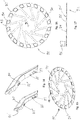
- a brake disk 90 comprising a measuring ring 92 is arranged on this front wheel 3, which brake disk will be described in detail below and is part of an incremental measuring path system.
- the dropout 8 is part of the bicycle frame 1, it being connected to seat stays 5 and chain stays 7 in a known manner.
- Light elements 80 are integrated on the dropouts 8 and in particular in the area adjacent to the seat stays 5, which are explained in more detail below.
- the bicycle frame 1 comprises a drive bearing area 24, on which a drive bearing housing 26 for accommodating a particularly battery-operated auxiliary motor 28 is formed.
- the auxiliary motor 28 can for example be an electric motor and in particular an electric motor with a crank drive. The corresponding crank is not shown here.
- the bicycle frame 1 also comprises a frame tube 10 which runs between the steering head area 20 and the drive bearing area 24.
- the frame tube 10 can be referred to as a down tube. It optionally runs in an inclined design from a steering head area 20 arranged at the top in relation to the longitudinal plane of the bicycle and an engine bearing area arranged essentially centrally at the bottom.
- the frame tube 10 is designed such that a battery 104, in particular for the auxiliary drive 28, can be inserted into its interior 12 and a battery receiving section 14 running axially there.
- the battery receiving section 14 is equipped with an insertion opening 18 running at the end 16, via which the battery 104 can be pushed into the battery receiving section 14 with its end 102 first.
- Fig. 10 is dedicated to the detailed representation of the battery 104.
- the bicycle frame is optionally designed such that the battery 104 can be pushed into the battery receiving portion 14 axially to the main extension axis Ax of the battery receiving portion 14 along an insertion direction Rx. If, as is optionally possible, the insertion opening 18 is arranged on the drive bearing side 24, the battery 104 is inserted from the underside of the bicycle.
- the battery and the battery receiving section 14 or the insertion opening 18 in such a way that the battery can be pushed completely axially, that is to say along the axis Ax, into the battery receiving section 14.
- the battery has a small swivel angle ⁇ (see Fig. 4 ) runs through during the insertion and is gradually arranged with its main axis of extension A B coaxially to the main axis of extension Ax of the battery receiving portion 14 during axial insertion.
- the swivel angle ⁇ here is preferably a maximum of 25 °, optionally a maximum of 15 °, further optionally a maximum of 5 °.
- the insertion opening 18 is optionally arranged in particular on the drive bearing side, on the end face of the frame tube 10. As shown, the insertion opening can also extend partially into the outer surface of the frame tube 10.
- the end face it is possible for the end face to be viewed as a surface defined orthogonally to the main axis of extension Ax. It is also possible that the end face is viewed as a surface which is designed to deviate from this orthogonal surface by a maximum of an angle ⁇ . This is for example in Fig. 2 shown.
- the angle ⁇ here is preferably a maximum of ⁇ 25 °, optionally a maximum of ⁇ 15 ° and further optionally a maximum of ⁇ 5 °.
- the jacket surface of the frame tube 10 is closed to at least 90%, in particular at least 95%, in the area of the battery receiving section 14.
- an axial extension 22 of the clearance profile (see Fig. 3 ) of the battery receiving section 14 is formed on the frame tube 10 of the drive bearing area 24, in particular comprising a drive bearing housing 26 for receiving the auxiliary drive 28.
- the arrangement is optionally selected such that the battery 104 can be pushed laterally past an auxiliary drive 28 stored in the drive bearing housing 26 into the battery receiving section 14 is.
- a drive bearing housing formed in the clearance profile is optionally designed and / or arranged in such a way that a battery can be pushed past it into the battery receiving section 14.
- the clearance profile here is in particular the air space enclosed in cross section which the battery requires in order to be pushed into the battery receiving section.
- a clearance profile within the scope of the invention is the defined boundary line of the vertical transverse plane of the path of insertion of the battery into the battery receiving section.
- the drive bearing housing 26 can be connected circumferentially to the frame tube 10 in such a way that the battery can be pushed laterally past it or past an auxiliary drive 28 mounted in the drive bearing housing into the interior 12.
- a cover element 36 can be provided so that the insertion opening 12 can be releasably arranged on the frame tube 10 and / or on the drive bearing housing 24 in a covering manner.
- This cover element 36 can function in particular as a ram protection element.
- a battery guide means 30 is arranged in the interior 12 of the frame tube 10, which forms a sliding guide for axially inserting the battery 104 into the battery receiving section 14.
- the battery guide means 30 at least one guide spring 32 which is formed integrally on the frame tube 10, for example.
- at least one guide groove 106 which is at least partially complementary thereto, is formed in the battery 104.
- Guide spring 32 and guide groove 106 engage one another in such a way that when the battery is axially pushed into the battery receiving section 14, the battery is safely guided into the interior 12 of the tube 10.
- guide elements 34 In addition to the guide spring 32, further guide elements 34 (see e.g. Fig. 9 ) be formed on the frame tube 10 or other components of the bicycle frame 1, which guarantee guidance of the battery in and in the frame tube. These guide elements 34 can also be designed as bearing elements and, as will be described in detail below, as temporary battery holding means 54.
- the battery guide means and in particular the guide spring 32 are also designed to protrude axially outward via the insertion opening 18 from the battery receiving section 14 and in particular the interior 12 of the frame tube 10. In this way, this is also possible in, for example Fig. 4 shown, the battery can very easily be inserted into the guide coupling between the guide spring 32 and the guide groove 106.
- the battery guide means in particular in the outwardly protruding area, has an especially inclined guide element 31 in order to bring the battery and the guide means arranged on it, here for example a guide groove, into coupling engagement with the corresponding counter guide means, for example the guide spring 32 .
- the guide element can also form at least part of the guide spring itself.
- At least one cable guide 56, 57 can be provided in the interior 12 of the frame tube 10 in order to guide cables inside the frame tube 10.
- These cables can be, for example, lines, shift cables, brake cables of the same elements, as has already been defined above. It is possible to provide such cable guides as open cable guides 56 or as closed cable guides 57. It is precisely the open cable ducts 56 that allow cable ducts with large plugs or similar end elements to be guided, since these can optionally be introduced into this cable duct 56, in particular orthogonally to the main axis of extension Ax. Basically, but especially in the case of the open cable ducts 56, a clamping means is preferably provided in order to hold the cable ducts guided therein securely and in particular in a vibration-resistant manner.
- the bicycle frame optionally also comprises a battery locking means 40, which is optionally provided in the interior 12 of the frame tube 10.
- This battery locking means 40 is used to lock the battery 104 in the battery receiving section 14.
- It optionally includes an end cap 42, which can be inserted into the interior 12 of the frame tube 10 via the insertion opening 18 and can be releasably locked there. In this way, a battery 104 pushed into the battery receiving section 14 can be locked, in particular against being pushed out axially.
- the end cap is also in detail in Fig. 10 shown.
- the end cap 42 has at least one locking means 44 and the frame tube 10 has at least one locking counter-means 46, or vice versa.
- the means can be brought into a locking position by means of an actuating means 50, locking the battery 104 in the battery receiving section 14 with one another, and into an unlocking position, releasing the battery 104 in the battery receiving section 14.
- the locking means 44 can have at least one locking pin 48 and the locking counter-means 46 (see FIG Figures 6 and 7th ) at least one complementary locking pin receptacle 52, or vice versa.
- the locking pin 48 can engage the end cap 42 in a locking manner in the locking pin receptacle 52, and in the unlocking position the end cap 42 can be unlocked and disengaged from the locking pin receptacle.
- the actuating means 50 mentioned for this purpose can, for example, comprise a spring preloading device which preloads the locking bolts into the locking position (not shown).
- the locking bolts 48 can protrude orthogonally to the main axis of extension A B of the battery and in particular be elastically supported.
- the end cap 42 has at least part of the battery guide means and in particular a guide groove 38 and / or a guide spring.
- the locking means and counter locking means are preferably designed so that the locking bolts are briefly pushed back into the unlocking position when they are pushed in, in order to then jump back into the locking position and, in particular, engage in the locking bolt receptacle 52. It is also conceivable to design the locking bolts in such a way that they can be moved from the locking position into the unlocking position via an actuating means 50 having a lever, a key or a similar actuator, as already described above, in order to insert the battery into the battery receiving section , optionally without coming into contact with or locking into the locking pin receptacles 52.
- the actuating means for unlocking can be designed in order to push the locking bolts that have engaged in the locking pin receptacles back into the unlocking position and thus allow the battery and in particular the end cap 42 to be removed. All methods known from the prior art can be used here.
- the locking means and counter locking means so that they can be controlled by means of the actuating means, in order to be able to actively assume a locking position, an unlocking position and / or both.
- the bicycle frame can be provided with a rail system 70, in particular in the interior 12 of the frame tube 10, or such a rail system can be introduced into it.
- the rail system optionally has at least one rail 72 which, in particular, can be pushed axially into a complementary rail receptacle 74, which is optionally formed integrally on the frame tube 10.
- the rail system 70 can optionally be able to be fixed against an axial movement on the frame tube 10 by means of a fixing means 76 and in particular a screw. This is for example in Fig. 6 shown.
- the rail system 70 can be designed to accommodate a battery locking means 40 and / or a battery guide means 30 and / or a battery connection means 60 and / or a battery temporary holding means 54 or have such a device.
- a battery locking means 40 and / or a battery guide means 30 and / or a battery connection means 60 and / or a battery temporary holding means 54 or have such a device.
- the battery locking means 40 and the battery guide means 30 have already been described above by way of example.
- counter-locking means 46 for example in the form of locking pin receptacles 52, are optionally provided on the rails 72 of the rail system 70, in particular in the region of the insertion opening 18.
- different locking countermeans can be provided along the rail 72 in order to allow locking with different, in particular differently long, batteries and / or differently designed locking means 44.
- the battery locking means 40 can comprise a locking bolt which is pivotably mounted on the frame tube and / or on the battery and the battery can be locked in the frame tube.
- the locking bar can be pivotably mounted on the frame tube and / or the battery as a locking means and can be in the locking position against or in a locking counter-means, for example an end face of the battery or a complementary receptacle on the frame tube.
- the battery connection means 60 preferably and optionally in the area of the end of the frame tube 10 facing the steering head area 20 and in particular adjacent to the battery receiving section 14 has a battery hub 62 for connecting the battery 104 pushed into the battery receiving section 14.
- the battery hub 62 is preferably attached to the rail system 70 so that it can be pushed together with it into the interior space 12 of the frame tube 10 in order to remain there and to be coupled to the battery 104, which is pushed into the battery receiving section 14.
- the battery hub 62 can, for example, have a plug 66 (see FIG Fig. 7 ), which is complementary to a plug receptacle 64 (see Fig.
- Plug or plug receptacle are preferably designed so that they form a magnetic adhesive force and thus, for example, temporarily store the battery 104 in the battery receptacle section 14 in a clamped manner, in particular against the action of gravity in the unlocked position.
- the temporary adhesive force or locking force is designed such that it can be overcome manually by a user via a tensile force in the opposite direction to the direction of insertion Rx of the battery into the battery receiving section 14.
- the temporary battery backup preferably serves to conveniently lock the battery 104 in the frame tube 10.
- the battery connection means 60 optionally also forms the temporary battery holding means 54.
- the battery temporary holding means 54 by means of a clamping system which holds the battery 104 in the battery receiving section 14 in a clamped manner against the action of gravity in the unlocked position.
- This can be done, for example, by appropriately designed rails 72 of the Rail system 70 take place, which bear directly or indirectly with a clamping force, resulting in an adhesive force, on the battery 104.
- the same can also be achieved via appropriately designed battery holding means 54, for example designed integrally on the frame tube. These are for example in Fig. 9 shown.
- Such battery holding means are preferably designed to be elastic.
- Such temporary battery holding means are preferably designed as elastic temporary holding means and in particular clamping means.
- they can be designed as battery guide means and battery storage means.
- the bicycle frame 1 optionally comprises at least one light element 80 integrated in the dropout 8 and further optionally an incremental measuring path system, with at least one measuring ring 92, here for example arranged on the front wheel 3, as part of the incremental path measuring system, for example for a speedometer unit. It is conceivable to arrange this measuring path system and in particular the measuring ring also or alternatively in the area of the rear wheel.
- the Figures 11 to 14 show in detail at least one in Fig. 1 shown, integrated in the dropout 8 light element 80.
- a light element 80 can be used not only in connection with the bicycle frame 1 shown here, but with any type of bicycle frame.
- the light element 80 is here integrated into the dropout 8 and in particular into the dropout 8 flush with the surface.
- the dropout 8 has a recess 82 into which the light element 80 can be inserted and fixed by means of fastening elements.
- the access to the assembly area can optionally be covered by a cover element 85, as shown in FIG Fig. 13
- the fasteners preferably engage in fastener receptacles 88 (see Fig.
- the fasteners can optionally be screws.
- guides 87 which engage in corresponding guide receptacles (not shown) on the dropout 8 and so one Allow pre-positioning of the light element 80 in the recess 82.
- the light element 80 is preferably designed in such a way that it can be seen from the rear of the bicycle, but also from the side of the bicycle. It is preferably arranged above the axle receptacle 89 for receiving the rear wheel 6.
- the left-hand and right-hand lighting elements of a bicycle frame are designed to be identical.
- the light element 80 can be designed, for example, as a rear light, as a brake light, but also as a flashing or similar light, in order to allow signaling when the bicycle is being operated.
- such a light element 80 integrated into the dropout 8 has an advantageous function.
- the bicycle 100 optionally comprises an incremental distance measuring system, part of which is a measuring ring 92 and a sensor means 96 operating with it Bicycle 100 according to the invention, but can be applied to any type of bicycle.
- the measuring ring 92 is optionally formed or fastened on the brake disk 90 shown here.
- the measuring ring 92 is optionally designed to be rotationally symmetrical to an axis center 96 which, in the assembled state on the bicycle front tire 3, is arranged co-axially to the assembly axis (not shown).
- the measuring ring 92 has a plurality of knife elevations 94, which protrude in the form of impressions from the measuring ring 92 and optionally in the assembled state (see FIG Fig.
- the sensor means is designed to detect the elevations 94 or, in the other previously mentioned embodiment, the borders 93 while they are rotating past the measuring sensor 96. It is known from the prior art to provide such an incremental measuring path system by means of a measuring ring, in which the measuring ring has recesses and the measuring sensor detects these recesses or the webs between the recesses. Such a measuring system is, however, prone to errors; it had to be improved.
- the now presented incremental measuring path system comprising the measuring ring 92 and the elevations 94 formed thereon provides a much better and more reliable system.
- At least one elevation 94 can be larger or smaller than the remaining elevations. It thus provides a calibration element 98 which can in particular prevent manipulation of the measurement results.
- a correspondingly assigned trigger unit for example on the speedometer 99 of the bicycle (see for example Fig. 1 )
- a measuring method can be initiated in which the revolutions of the measuring ring 92 are counted on the basis of the passage of the calibration element 98.
- a manipulation of the speed measuring system can be made more difficult.
- such an incremental distance measuring system and in particular the measuring rings 92 have a particular advantage.
- the larger formation of at least one elevation 94 or of the calibration element 98 relates here optionally to the length in the circumferential direction, that is to say the length which runs past the sensor means during the rotation.
- the calibration element 98 viewed in the circumferential direction, is longer than the remaining elevations 94 and in particular by at least 5%, further optionally by at least 10% longer.
Landscapes
- Engineering & Computer Science (AREA)
- Mechanical Engineering (AREA)
- Chemical & Material Sciences (AREA)
- Combustion & Propulsion (AREA)
- Transportation (AREA)
- Battery Mounting, Suspending (AREA)
Claims (13)
- Cadre de bicyclette (1) pour une bicyclette (100) pourvue d'un entraînement auxiliaire (28) fonctionnant sur batterie, comprenant au moins un tube de cadre (10), en particulier un tube de pédalier, qui s'étend entre une zone de tête de direction (20) et une zone de palier d'entraînement (24) et qui présente une section de réception de batterie (14) s'étendant axialement dans son espace intérieur (12), pour recevoir une batterie (104), en particulier pour l'entraînement auxiliaire (28), dans lequel la section de réception de batterie (14) présente une ouverture d'insertion (18) s'étendant frontalement (16) et par l'intermédiaire de laquelle la batterie (104) peut être introduite dans la section de réception de batterie (14) avec sa face frontale (102) devant, dans lequel au moins une partie d'un moyen de guidage de batterie (30) est agencée dans l'espace intérieur (12) du tube de cadre (10), qui forme un guide de coulissement pour une introduction axiale de la batterie (104) dans la section de réception de batterie (14), dans lequel le moyen de guidage de batterie (30) présente au moins un ressort de guidage (32) facultativement formé d'un seul tenant sur le tube de cadre (10), et la batterie (104) présente au moins une rainure de guidage (106) complémentaire de celui-ci au moins par endroits, ou inversement
caractérisé en ce que
le ressort de guidage (32) formé sur le tube de cadre (10) ou la rainure de guidage formée sur le tube de cadre (10) fait saillie axialement vers l'extérieur, par l'intermédiaire de l'ouverture d'insertion (18), à partir de la section de réception de batterie (14) et en particulier à partir de l'espace intérieur (12). - Cadre de bicyclette selon la revendication 1,
caractérisé en ce que
la batterie (104) peut être insérée dans la section de réception de batterie (14) le long d'une direction d'insertion (Rx) axialement par rapport à l'axe d'extension principal (Ax) de la section de réception de batterie (14). - Cadre de bicyclette selon l'une quelconque des revendications précédentes,
caractérisé en ce que
l'ouverture d'insertion (18) est agencée au moins partiellement, en particulier sur la face frontale du palier d'entraînement, sur le tube de cadre (10). - Cadre de bicyclette selon l'une quelconque des revendications précédentes,
caractérisé en ce que
au moins 90 %, en particulier au moins 95 % de la surface extérieure du tube de cadre (10) sont fermés dans la zone de la section de réception de batterie (14). - Cadre de bicyclette selon l'une quelconque des revendications précédentes,
caractérisé en ce que
la zone de palier d'entraînement (24) est formée latéralement sur le tube de cadre et en particulier à l'extérieur d'un prolongement axial (22) du profil d'espace libre de la section de réception de batterie (14) sur le tube de cadre (10), en particulier comprenant un logement de palier d'entraînement (26) pour recevoir l'entraînement auxiliaire (28), de telle sorte que la batterie (104) peut être poussée latéralement au-delà de l'entraînement auxiliaire (28) monté dans le logement de palier d'entraînement (26) jusque dans la section de réception de batterie (14). - Cadre de bicyclette selon l'une quelconque des revendications précédentes,
caractérisé en ce que
au moins un moyen d'arrêt de batterie (40) est prévu, en particulier dans l'espace intérieur (12) du tube de cadre (10), pour arrêter la batterie (104) dans la section de réception de batterie (14), comprenant en particulier un capuchon d'extrémité (42) qui peut être inséré dans l'espace intérieur (12) du tube de cadre (10) via l'ouverture d'insertion (18) et qui peut y être verrouillé de manière libérable, et verrouille ainsi une batterie (104) insérée dans la section de réception de batterie (14), en particulier à l'encontre d'une poussée axiale. - Cadre de bicyclette selon la revendication 6,
caractérisé en ce que
le capuchon d'extrémité (42) comporte au moins un moyen de verrouillage (44) et le tube de cadre (10) comporte au moins un moyen de verrouillage antagoniste (46), ou vice versa, qui peuvent être amenés dans une position de verrouillage mutuel au moyen d'un moyen d'actionnement (50), la batterie (104) étant verrouillée dans la section de réception de batterie (14), et dans une position de déverrouillage par libération de la batterie (104) dans la section de réception de batterie (14). - Cadre de bicyclette selon la revendication 7,
caractérisé en ce que
le moyen de verrouillage (44) comporte au moins un boulon de blocage (48), et le moyen de verrouillage antagoniste (46) comporte au moins un logement de boulon de serrage complémentaire (52), ou vice versa, dans lequel le boulon de serrage (48) est en prise dans le logement de boulon de serrage (52) de manière à verrouiller le capuchon d'extrémité (42) dans la position de verrouillage et n'est pas en prise dans le logement de boulon de serrage (52) de manière à déverrouiller le capuchon d'extrémité (42) dans la position de déverrouillage. - Cadre de bicyclette selon l'une quelconque des revendications 7 ou 8 lorsqu'elles dépendent de la revendication 2,
caractérisé en ce que
au moins un moyen de retenue temporaire de batterie (54), et en particulier un système de serrage de batterie, est prévus, en particulier dans l'espace intérieur (12) du tube de cadre (10), de telle sorte que la batterie (104) est montée de manière fixe dans la section de réception de batterie (14) à l'encontre de l'action de la gravité dans la position de déverrouillage, mais peut être retirée manuellement par un utilisateur par l'intermédiaire d'une force de traction dans une direction opposée à la direction d'insertion (Rx). - Cadre de bicyclette selon l'une quelconque des revendications précédentes,
caractérisé en ce que
au moins un moyen de connexion de batterie (60) est prévu, en particulier dans l'espace intérieur (12) du tube de cadre (10), qui présente une borne de batterie (62), en particulier dans la zone de l'extrémité du tube de cadre (10) tournée vers la zone de tête de direction (20) et en particulier adjacente à la section de réception de batterie (14), pour connecter la batterie insérée dans la section de réception de batterie (14). - Cadre de bicyclette selon l'une quelconque des revendications précédentes,
caractérisé en ce que
en particulier dans l'espace intérieur (12) du tube de cadre (10), un système de rails (70) est formé et/ou peut être introduit dans celui-ci, qui présente au moins un rail (72) qui peut être notamment poussé axialement dans un logement de rail complémentaire (74) qui est formé le cas échéant d'un seul tenant sur le tube de cadre (10), dans lequel le système de rail (70) peut être fixé de manière sélective sur le tube de cadre (10) à l'encontre d'un déplacement axial au moyen d'un moyen de fixation (76), et dans lequel le système de rails (70) est formé pour recevoir un moyen de verrouillage de batterie (40) et/ou un moyen de guidage de batterie (30) et/ou un moyen de connexion de batterie (60) et/ou un moyen de retenue temporaire de batterie (54) ou présentant un tel moyen. - Cadre de bicyclette selon la revendication 11,
caractérisé en ce que
le système de rails (70) est conçu de manière à pouvoir être inséré dans l'espace intérieur (12) du tube de cadre (10) conjointement avec au moins des parties du moyen d'arrêt de batterie (40) et/ou du moyen de guidage de batterie (30) et/ou du moyens de connexion de batterie (60) et/ou du moyens de retenue temporaire de batterie (54). - Bicyclette avec un entraînement auxiliaire fonctionnant sur batterie et un cadre de bicyclette selon l'une quelconque des revendications précédentes.
Priority Applications (4)
| Application Number | Priority Date | Filing Date | Title |
|---|---|---|---|
| EP18181933.5A EP3590813B1 (fr) | 2018-07-05 | 2018-07-05 | Bicyclette pourvue d'un entraînement auxiliaire fonctionnant sur batterie et cadre de bicyclette correspondant |
| EP18182236.2A EP3590814B1 (fr) | 2018-07-05 | 2018-07-06 | Bicyclette pourvue d'un entraînement auxiliaire fonctionnant sur batterie et cadre de bicyclette correspondant |
| EP19184340.8A EP3590808B1 (fr) | 2018-07-05 | 2019-07-04 | Procédé de fixation d'un porte-bagages sur une bicyclette, bicyclette ainsi que cadre de bicyclette et élément d'éclairage pour une telle bicyclette |
| EP19184336.6A EP3590812B1 (fr) | 2018-07-05 | 2019-07-04 | Système de mesure incrémental pour une bicyclette, bicyclette, moyen émetteur de signal et procédé de fabrication |
Applications Claiming Priority (1)
| Application Number | Priority Date | Filing Date | Title |
|---|---|---|---|
| EP18181933.5A EP3590813B1 (fr) | 2018-07-05 | 2018-07-05 | Bicyclette pourvue d'un entraînement auxiliaire fonctionnant sur batterie et cadre de bicyclette correspondant |
Publications (2)
| Publication Number | Publication Date |
|---|---|
| EP3590813A1 EP3590813A1 (fr) | 2020-01-08 |
| EP3590813B1 true EP3590813B1 (fr) | 2021-12-15 |
Family
ID=62874664
Family Applications (2)
| Application Number | Title | Priority Date | Filing Date |
|---|---|---|---|
| EP18181933.5A Active EP3590813B1 (fr) | 2018-07-05 | 2018-07-05 | Bicyclette pourvue d'un entraînement auxiliaire fonctionnant sur batterie et cadre de bicyclette correspondant |
| EP18182236.2A Active EP3590814B1 (fr) | 2018-07-05 | 2018-07-06 | Bicyclette pourvue d'un entraînement auxiliaire fonctionnant sur batterie et cadre de bicyclette correspondant |
Family Applications After (1)
| Application Number | Title | Priority Date | Filing Date |
|---|---|---|---|
| EP18182236.2A Active EP3590814B1 (fr) | 2018-07-05 | 2018-07-06 | Bicyclette pourvue d'un entraînement auxiliaire fonctionnant sur batterie et cadre de bicyclette correspondant |
Country Status (1)
| Country | Link |
|---|---|
| EP (2) | EP3590813B1 (fr) |
Families Citing this family (18)
| Publication number | Priority date | Publication date | Assignee | Title |
|---|---|---|---|---|
| US10906610B2 (en) * | 2018-08-21 | 2021-02-02 | Specialized Bicycle Components, Inc. | Ebike with partially exposed battery |
| JP7156960B2 (ja) * | 2019-02-01 | 2022-10-19 | 株式会社シマノ | 人力駆動車用のドライブユニット、人力駆動車用のドライブシステム、および人力駆動車用のバッテリユニット |
| TWI853975B (zh) * | 2019-07-16 | 2024-09-01 | 美商希瑞萬自行車公司 | 電動腳踏車 |
| USD929268S1 (en) | 2019-08-20 | 2021-08-31 | Serial 1 Cycle Company, Llc | Bicycle |
| US11639211B2 (en) * | 2019-11-19 | 2023-05-02 | Paul Michael Farrell | Bicycle frame for an e-bike |
| DE102020104783A1 (de) | 2020-02-24 | 2021-08-26 | Volocopter Gmbh | Batteriehaltevorrichtung, Batteriesystem, Fluggerät und Verfahren zum Wechseln einer Batterie für ein Fluggerät |
| WO2021185487A1 (fr) | 2020-03-19 | 2021-09-23 | Scott Sports Sa | Bicyclette électrique |
| CN111232105B (zh) * | 2020-03-27 | 2025-06-10 | 东莞市台铃车业有限公司 | 电池仓组件及电动车 |
| IT202000018547A1 (it) | 2020-07-30 | 2022-01-30 | Fantic Motor S P A | Struttura di bicicletta con batteria rimovibile. |
| JP7554596B2 (ja) * | 2020-07-31 | 2024-09-20 | 株式会社シマノ | 人力駆動車用のバッテリ保持装置、人力駆動車用のドライブユニット、および、人力駆動車用のバッテリユニット |
| DE202020104966U1 (de) | 2020-08-27 | 2021-11-30 | Canyon Bicycles Gmbh | Batterieeinheit sowie Fahrradrahmen |
| DE202020105636U1 (de) | 2020-10-01 | 2022-01-07 | Canyon Bicycles Gmbh | Fahrrad-Batterieeinrichtung |
| CN112141246A (zh) * | 2020-10-30 | 2020-12-29 | 永安行科技股份有限公司 | 一种氢动力车的走线、走气结构及氢动力车 |
| EP4144625B1 (fr) | 2021-09-01 | 2025-08-06 | SCOTT Sports SA | Vélo électrique avec porte batterie |
| TWI808585B (zh) * | 2021-12-29 | 2023-07-11 | 彥豪金屬工業股份有限公司 | 自行車碟煞卡鉗及自行車組件 |
| CN115195922A (zh) * | 2022-08-19 | 2022-10-18 | 珠海蓝图控制器科技有限公司 | 一种自行车电池安装结构及自行车 |
| DE102022127802A1 (de) * | 2022-10-20 | 2024-04-25 | Sram Deutschland Gmbh | Elektrische Fahrrad-Antriebseinheit sowie Fahrradrahmen, Rahmenschnittstellen-Einheit und Energiespeichereinrichtung für elektrische Fahrrad-Antriebseinheit |
| CN219857465U (zh) * | 2023-05-29 | 2023-10-20 | 佛山市南海三鹰运动自行车有限公司 | 一种内藏式下抽电池安装结构 |
Family Cites Families (4)
| Publication number | Priority date | Publication date | Assignee | Title |
|---|---|---|---|---|
| JPH1159532A (ja) * | 1997-08-11 | 1999-03-02 | Sony Corp | 電気自転車 |
| JP2000272567A (ja) * | 1999-03-29 | 2000-10-03 | Yamaha Motor Co Ltd | 電動自転車のバッテリ脱着構造 |
| DE102016205539B3 (de) * | 2016-04-04 | 2017-09-28 | QCS Quality Consult Service GmbH | Fahrzeugrahmen und Fahrzeug |
| DE102016010338A1 (de) * | 2016-08-29 | 2018-03-01 | BMZ GmbH | Vorrichtung zum Energiespeichern und/oder Energieabgeben und Verfahren zur Verwendung einer Vorrichtung zum Energiespeichern und/oder Energieabgeben |
-
2018
- 2018-07-05 EP EP18181933.5A patent/EP3590813B1/fr active Active
- 2018-07-06 EP EP18182236.2A patent/EP3590814B1/fr active Active
Non-Patent Citations (1)
| Title |
|---|
| None * |
Also Published As
| Publication number | Publication date |
|---|---|
| EP3590814A1 (fr) | 2020-01-08 |
| EP3590814B1 (fr) | 2022-04-27 |
| EP3590813A1 (fr) | 2020-01-08 |
Similar Documents
| Publication | Publication Date | Title |
|---|---|---|
| EP3590813B1 (fr) | Bicyclette pourvue d'un entraînement auxiliaire fonctionnant sur batterie et cadre de bicyclette correspondant | |
| EP2838782B1 (fr) | Membre de couplage compacte autoverrouillant | |
| EP0361155B1 (fr) | Support pour serrure avec traverse allongée | |
| AT504826A2 (de) | Bausatz und verfahren zum umrüsten eines fahrrades sowie fahrrad | |
| DE102018202437B4 (de) | Abnehmbares Zubehörteil und Rastverschluss dafür | |
| DE19848231A1 (de) | Vorrichtung zum lösbaren Verbinden mit einem Bügel | |
| DE102011079595B4 (de) | Fahrrad mit einem klappbaren Rahmen | |
| EP0072945A1 (fr) | Boîte de sécurité pouvant être fermée à clé pour véhicules à deux roues | |
| DE102017007362A1 (de) | Elektromotor, insbesondere für Fahrzeug | |
| EP3587233B1 (fr) | Élément de cadre d'un deux roues permettant de recevoir une unité d'alimentation en énergie | |
| DE102021212301A1 (de) | Adapter zum Befestigen an einem Energiespeicher, Energiespeicher, Ankoppeleinheit, System zum Ankoppeln eines Energiespeichers | |
| DE102023116017A1 (de) | Schlosskasten und Anordnung umfassend einen Schlosskasten | |
| EP0594954A1 (fr) | Serrure, en particulier pour bicyclette | |
| DE102011013250A1 (de) | Fahrrad mit mindestens einem werkzeuglos abnehmbaren Pedal | |
| EP0125375B1 (fr) | Frein sur jante pour cycle | |
| DE3632680C2 (fr) | ||
| EP3219520B1 (fr) | Système d'attelage pour véhicules automobiles | |
| EP1712458B1 (fr) | Unité réalisée avec un antivol de bicyclette | |
| AT522762B1 (de) | Schloss | |
| DE29619084U1 (de) | Mechanische Sperrvorrichtung für Fahrräder | |
| EP3476655B1 (fr) | Unité porteuse pour un dispositif support de toit d'un véhicule automobile | |
| DE9214669U1 (de) | Schloß, insbesondere für Fahrrad o.dgl. | |
| DE19857266B4 (de) | Drehsperre | |
| EP4452665B1 (fr) | Moyeu de roue avec moyen antivol | |
| DE102024128239A1 (de) | Elektronisches Rahmenschloss |
Legal Events
| Date | Code | Title | Description |
|---|---|---|---|
| PUAI | Public reference made under article 153(3) epc to a published international application that has entered the european phase |
Free format text: ORIGINAL CODE: 0009012 |
|
| STAA | Information on the status of an ep patent application or granted ep patent |
Free format text: STATUS: THE APPLICATION HAS BEEN PUBLISHED |
|
| AK | Designated contracting states |
Kind code of ref document: A1 Designated state(s): AL AT BE BG CH CY CZ DE DK EE ES FI FR GB GR HR HU IE IS IT LI LT LU LV MC MK MT NL NO PL PT RO RS SE SI SK SM TR |
|
| AX | Request for extension of the european patent |
Extension state: BA ME |
|
| STAA | Information on the status of an ep patent application or granted ep patent |
Free format text: STATUS: REQUEST FOR EXAMINATION WAS MADE |
|
| 17P | Request for examination filed |
Effective date: 20200619 |
|
| RBV | Designated contracting states (corrected) |
Designated state(s): AL AT BE BG CH CY CZ DE DK EE ES FI FR GB GR HR HU IE IS IT LI LT LU LV MC MK MT NL NO PL PT RO RS SE SI SK SM TR |
|
| STAA | Information on the status of an ep patent application or granted ep patent |
Free format text: STATUS: EXAMINATION IS IN PROGRESS |
|
| 17Q | First examination report despatched |
Effective date: 20200921 |
|
| GRAP | Despatch of communication of intention to grant a patent |
Free format text: ORIGINAL CODE: EPIDOSNIGR1 |
|
| STAA | Information on the status of an ep patent application or granted ep patent |
Free format text: STATUS: GRANT OF PATENT IS INTENDED |
|
| RIC1 | Information provided on ipc code assigned before grant |
Ipc: B62M 6/90 20100101AFI20210720BHEP Ipc: B62J 43/13 20200101ALI20210720BHEP Ipc: B62J 43/28 20200101ALI20210720BHEP Ipc: B62K 19/40 20060101ALI20210720BHEP Ipc: B62K 19/06 20060101ALI20210720BHEP Ipc: B62M 6/55 20100101ALN20210720BHEP Ipc: B62L 1/00 20060101ALN20210720BHEP Ipc: B62J 6/055 20200101ALN20210720BHEP Ipc: B62J 6/04 20200101ALN20210720BHEP Ipc: B62K 19/34 20060101ALN20210720BHEP Ipc: B62K 25/02 20060101ALN20210720BHEP Ipc: B62K 3/04 20060101ALN20210720BHEP Ipc: B62J 45/413 20200101ALN20210720BHEP Ipc: B62J 45/423 20200101ALN20210720BHEP Ipc: B62J 11/10 20200101ALN20210720BHEP Ipc: B62J 6/20 20060101ALN20210720BHEP |
|
| INTG | Intention to grant announced |
Effective date: 20210818 |
|
| GRAS | Grant fee paid |
Free format text: ORIGINAL CODE: EPIDOSNIGR3 |
|
| GRAA | (expected) grant |
Free format text: ORIGINAL CODE: 0009210 |
|
| STAA | Information on the status of an ep patent application or granted ep patent |
Free format text: STATUS: THE PATENT HAS BEEN GRANTED |
|
| AK | Designated contracting states |
Kind code of ref document: B1 Designated state(s): AL AT BE BG CH CY CZ DE DK EE ES FI FR GB GR HR HU IE IS IT LI LT LU LV MC MK MT NL NO PL PT RO RS SE SI SK SM TR |
|
| REG | Reference to a national code |
Ref country code: GB Ref legal event code: FG4D Free format text: NOT ENGLISH Ref country code: CH Ref legal event code: EP |
|
| REG | Reference to a national code |
Ref country code: IE Ref legal event code: FG4D Free format text: LANGUAGE OF EP DOCUMENT: GERMAN Ref country code: DE Ref legal event code: R096 Ref document number: 502018008193 Country of ref document: DE |
|
| REG | Reference to a national code |
Ref country code: AT Ref legal event code: REF Ref document number: 1455313 Country of ref document: AT Kind code of ref document: T Effective date: 20220115 |
|
| REG | Reference to a national code |
Ref country code: LT Ref legal event code: MG9D |
|
| REG | Reference to a national code |
Ref country code: NL Ref legal event code: MP Effective date: 20211215 |
|
| PG25 | Lapsed in a contracting state [announced via postgrant information from national office to epo] |
Ref country code: RS Free format text: LAPSE BECAUSE OF FAILURE TO SUBMIT A TRANSLATION OF THE DESCRIPTION OR TO PAY THE FEE WITHIN THE PRESCRIBED TIME-LIMIT Effective date: 20211215 Ref country code: LT Free format text: LAPSE BECAUSE OF FAILURE TO SUBMIT A TRANSLATION OF THE DESCRIPTION OR TO PAY THE FEE WITHIN THE PRESCRIBED TIME-LIMIT Effective date: 20211215 Ref country code: FI Free format text: LAPSE BECAUSE OF FAILURE TO SUBMIT A TRANSLATION OF THE DESCRIPTION OR TO PAY THE FEE WITHIN THE PRESCRIBED TIME-LIMIT Effective date: 20211215 Ref country code: BG Free format text: LAPSE BECAUSE OF FAILURE TO SUBMIT A TRANSLATION OF THE DESCRIPTION OR TO PAY THE FEE WITHIN THE PRESCRIBED TIME-LIMIT Effective date: 20220315 |
|
| PG25 | Lapsed in a contracting state [announced via postgrant information from national office to epo] |
Ref country code: SE Free format text: LAPSE BECAUSE OF FAILURE TO SUBMIT A TRANSLATION OF THE DESCRIPTION OR TO PAY THE FEE WITHIN THE PRESCRIBED TIME-LIMIT Effective date: 20211215 Ref country code: NO Free format text: LAPSE BECAUSE OF FAILURE TO SUBMIT A TRANSLATION OF THE DESCRIPTION OR TO PAY THE FEE WITHIN THE PRESCRIBED TIME-LIMIT Effective date: 20220315 Ref country code: LV Free format text: LAPSE BECAUSE OF FAILURE TO SUBMIT A TRANSLATION OF THE DESCRIPTION OR TO PAY THE FEE WITHIN THE PRESCRIBED TIME-LIMIT Effective date: 20211215 Ref country code: HR Free format text: LAPSE BECAUSE OF FAILURE TO SUBMIT A TRANSLATION OF THE DESCRIPTION OR TO PAY THE FEE WITHIN THE PRESCRIBED TIME-LIMIT Effective date: 20211215 Ref country code: GR Free format text: LAPSE BECAUSE OF FAILURE TO SUBMIT A TRANSLATION OF THE DESCRIPTION OR TO PAY THE FEE WITHIN THE PRESCRIBED TIME-LIMIT Effective date: 20220316 |
|
| PG25 | Lapsed in a contracting state [announced via postgrant information from national office to epo] |
Ref country code: NL Free format text: LAPSE BECAUSE OF FAILURE TO SUBMIT A TRANSLATION OF THE DESCRIPTION OR TO PAY THE FEE WITHIN THE PRESCRIBED TIME-LIMIT Effective date: 20211215 |
|
| PG25 | Lapsed in a contracting state [announced via postgrant information from national office to epo] |
Ref country code: SM Free format text: LAPSE BECAUSE OF FAILURE TO SUBMIT A TRANSLATION OF THE DESCRIPTION OR TO PAY THE FEE WITHIN THE PRESCRIBED TIME-LIMIT Effective date: 20211215 Ref country code: SK Free format text: LAPSE BECAUSE OF FAILURE TO SUBMIT A TRANSLATION OF THE DESCRIPTION OR TO PAY THE FEE WITHIN THE PRESCRIBED TIME-LIMIT Effective date: 20211215 Ref country code: RO Free format text: LAPSE BECAUSE OF FAILURE TO SUBMIT A TRANSLATION OF THE DESCRIPTION OR TO PAY THE FEE WITHIN THE PRESCRIBED TIME-LIMIT Effective date: 20211215 Ref country code: PT Free format text: LAPSE BECAUSE OF FAILURE TO SUBMIT A TRANSLATION OF THE DESCRIPTION OR TO PAY THE FEE WITHIN THE PRESCRIBED TIME-LIMIT Effective date: 20220418 Ref country code: ES Free format text: LAPSE BECAUSE OF FAILURE TO SUBMIT A TRANSLATION OF THE DESCRIPTION OR TO PAY THE FEE WITHIN THE PRESCRIBED TIME-LIMIT Effective date: 20211215 Ref country code: EE Free format text: LAPSE BECAUSE OF FAILURE TO SUBMIT A TRANSLATION OF THE DESCRIPTION OR TO PAY THE FEE WITHIN THE PRESCRIBED TIME-LIMIT Effective date: 20211215 Ref country code: CZ Free format text: LAPSE BECAUSE OF FAILURE TO SUBMIT A TRANSLATION OF THE DESCRIPTION OR TO PAY THE FEE WITHIN THE PRESCRIBED TIME-LIMIT Effective date: 20211215 |
|
| PG25 | Lapsed in a contracting state [announced via postgrant information from national office to epo] |
Ref country code: PL Free format text: LAPSE BECAUSE OF FAILURE TO SUBMIT A TRANSLATION OF THE DESCRIPTION OR TO PAY THE FEE WITHIN THE PRESCRIBED TIME-LIMIT Effective date: 20211215 |
|
| REG | Reference to a national code |
Ref country code: DE Ref legal event code: R097 Ref document number: 502018008193 Country of ref document: DE |
|
| PG25 | Lapsed in a contracting state [announced via postgrant information from national office to epo] |
Ref country code: IS Free format text: LAPSE BECAUSE OF FAILURE TO SUBMIT A TRANSLATION OF THE DESCRIPTION OR TO PAY THE FEE WITHIN THE PRESCRIBED TIME-LIMIT Effective date: 20220415 |
|
| PLBE | No opposition filed within time limit |
Free format text: ORIGINAL CODE: 0009261 |
|
| STAA | Information on the status of an ep patent application or granted ep patent |
Free format text: STATUS: NO OPPOSITION FILED WITHIN TIME LIMIT |
|
| PG25 | Lapsed in a contracting state [announced via postgrant information from national office to epo] |
Ref country code: DK Free format text: LAPSE BECAUSE OF FAILURE TO SUBMIT A TRANSLATION OF THE DESCRIPTION OR TO PAY THE FEE WITHIN THE PRESCRIBED TIME-LIMIT Effective date: 20211215 Ref country code: AL Free format text: LAPSE BECAUSE OF FAILURE TO SUBMIT A TRANSLATION OF THE DESCRIPTION OR TO PAY THE FEE WITHIN THE PRESCRIBED TIME-LIMIT Effective date: 20211215 |
|
| 26N | No opposition filed |
Effective date: 20220916 |
|
| PG25 | Lapsed in a contracting state [announced via postgrant information from national office to epo] |
Ref country code: SI Free format text: LAPSE BECAUSE OF FAILURE TO SUBMIT A TRANSLATION OF THE DESCRIPTION OR TO PAY THE FEE WITHIN THE PRESCRIBED TIME-LIMIT Effective date: 20211215 |
|
| PG25 | Lapsed in a contracting state [announced via postgrant information from national office to epo] |
Ref country code: MC Free format text: LAPSE BECAUSE OF FAILURE TO SUBMIT A TRANSLATION OF THE DESCRIPTION OR TO PAY THE FEE WITHIN THE PRESCRIBED TIME-LIMIT Effective date: 20211215 |
|
| REG | Reference to a national code |
Ref country code: CH Ref legal event code: PL |
|
| GBPC | Gb: european patent ceased through non-payment of renewal fee |
Effective date: 20220705 |
|
| REG | Reference to a national code |
Ref country code: BE Ref legal event code: MM Effective date: 20220731 |
|
| PG25 | Lapsed in a contracting state [announced via postgrant information from national office to epo] |
Ref country code: LU Free format text: LAPSE BECAUSE OF NON-PAYMENT OF DUE FEES Effective date: 20220705 Ref country code: LI Free format text: LAPSE BECAUSE OF NON-PAYMENT OF DUE FEES Effective date: 20220731 Ref country code: FR Free format text: LAPSE BECAUSE OF NON-PAYMENT OF DUE FEES Effective date: 20220731 Ref country code: CH Free format text: LAPSE BECAUSE OF NON-PAYMENT OF DUE FEES Effective date: 20220731 |
|
| PG25 | Lapsed in a contracting state [announced via postgrant information from national office to epo] |
Ref country code: IT Free format text: LAPSE BECAUSE OF FAILURE TO SUBMIT A TRANSLATION OF THE DESCRIPTION OR TO PAY THE FEE WITHIN THE PRESCRIBED TIME-LIMIT Effective date: 20211215 Ref country code: GB Free format text: LAPSE BECAUSE OF NON-PAYMENT OF DUE FEES Effective date: 20220705 Ref country code: BE Free format text: LAPSE BECAUSE OF NON-PAYMENT OF DUE FEES Effective date: 20220731 |
|
| P01 | Opt-out of the competence of the unified patent court (upc) registered |
Effective date: 20230522 |
|
| PG25 | Lapsed in a contracting state [announced via postgrant information from national office to epo] |
Ref country code: IE Free format text: LAPSE BECAUSE OF NON-PAYMENT OF DUE FEES Effective date: 20220705 |
|
| PG25 | Lapsed in a contracting state [announced via postgrant information from national office to epo] |
Ref country code: HU Free format text: LAPSE BECAUSE OF FAILURE TO SUBMIT A TRANSLATION OF THE DESCRIPTION OR TO PAY THE FEE WITHIN THE PRESCRIBED TIME-LIMIT; INVALID AB INITIO Effective date: 20180705 |
|
| PG25 | Lapsed in a contracting state [announced via postgrant information from national office to epo] |
Ref country code: MK Free format text: LAPSE BECAUSE OF FAILURE TO SUBMIT A TRANSLATION OF THE DESCRIPTION OR TO PAY THE FEE WITHIN THE PRESCRIBED TIME-LIMIT Effective date: 20211215 Ref country code: CY Free format text: LAPSE BECAUSE OF FAILURE TO SUBMIT A TRANSLATION OF THE DESCRIPTION OR TO PAY THE FEE WITHIN THE PRESCRIBED TIME-LIMIT Effective date: 20211215 |
|
| REG | Reference to a national code |
Ref country code: AT Ref legal event code: MM01 Ref document number: 1455313 Country of ref document: AT Kind code of ref document: T Effective date: 20230705 |
|
| PG25 | Lapsed in a contracting state [announced via postgrant information from national office to epo] |
Ref country code: MT Free format text: LAPSE BECAUSE OF FAILURE TO SUBMIT A TRANSLATION OF THE DESCRIPTION OR TO PAY THE FEE WITHIN THE PRESCRIBED TIME-LIMIT Effective date: 20211215 |
|
| PG25 | Lapsed in a contracting state [announced via postgrant information from national office to epo] |
Ref country code: AT Free format text: LAPSE BECAUSE OF NON-PAYMENT OF DUE FEES Effective date: 20230705 |
|
| PG25 | Lapsed in a contracting state [announced via postgrant information from national office to epo] |
Ref country code: AT Free format text: LAPSE BECAUSE OF NON-PAYMENT OF DUE FEES Effective date: 20230705 |
|
| PG25 | Lapsed in a contracting state [announced via postgrant information from national office to epo] |
Ref country code: TR Free format text: LAPSE BECAUSE OF FAILURE TO SUBMIT A TRANSLATION OF THE DESCRIPTION OR TO PAY THE FEE WITHIN THE PRESCRIBED TIME-LIMIT Effective date: 20211215 |
|
| PGFP | Annual fee paid to national office [announced via postgrant information from national office to epo] |
Ref country code: DE Payment date: 20251230 Year of fee payment: 8 |
|
| PGFP | Annual fee paid to national office [announced via postgrant information from national office to epo] |
Ref country code: AT Payment date: 20260410 Year of fee payment: 5 |