EP3591130A1 - Structure de plafond - Google Patents
Structure de plafond Download PDFInfo
- Publication number
- EP3591130A1 EP3591130A1 EP19175583.4A EP19175583A EP3591130A1 EP 3591130 A1 EP3591130 A1 EP 3591130A1 EP 19175583 A EP19175583 A EP 19175583A EP 3591130 A1 EP3591130 A1 EP 3591130A1
- Authority
- EP
- European Patent Office
- Prior art keywords
- steel
- steel elements
- beams
- elements
- plate
- Prior art date
- Legal status (The legal status is an assumption and is not a legal conclusion. Google has not performed a legal analysis and makes no representation as to the accuracy of the status listed.)
- Granted
Links
Images

Classifications
-
- E—FIXED CONSTRUCTIONS
- E04—BUILDING
- E04G—SCAFFOLDING; FORMS; SHUTTERING; BUILDING IMPLEMENTS OR AIDS, OR THEIR USE; HANDLING BUILDING MATERIALS ON THE SITE; REPAIRING, BREAKING-UP OR OTHER WORK ON EXISTING BUILDINGS
- E04G23/00—Working measures on existing buildings
- E04G23/02—Repairing, e.g. filling cracks; Restoring; Altering; Enlarging
-
- E—FIXED CONSTRUCTIONS
- E04—BUILDING
- E04B—GENERAL BUILDING CONSTRUCTIONS; WALLS, e.g. PARTITIONS; ROOFS; FLOORS; CEILINGS; INSULATION OR OTHER PROTECTION OF BUILDINGS
- E04B5/00—Floors; Floor construction with regard to insulation; Connections specially adapted therefor
- E04B5/02—Load-carrying floor structures formed substantially of prefabricated units
- E04B5/12—Load-carrying floor structures formed substantially of prefabricated units with wooden beams
-
- E—FIXED CONSTRUCTIONS
- E04—BUILDING
- E04C—STRUCTURAL ELEMENTS; BUILDING MATERIALS
- E04C2/00—Building elements of relatively thin form for the construction of parts of buildings, e.g. sheet materials, slabs, or panels
- E04C2/02—Building elements of relatively thin form for the construction of parts of buildings, e.g. sheet materials, slabs, or panels characterised by specified materials
- E04C2/26—Building elements of relatively thin form for the construction of parts of buildings, e.g. sheet materials, slabs, or panels characterised by specified materials composed of materials covered by two or more of groups E04C2/04, E04C2/08, E04C2/10 or of materials covered by one of these groups with a material not specified in one of the groups
-
- E—FIXED CONSTRUCTIONS
- E04—BUILDING
- E04G—SCAFFOLDING; FORMS; SHUTTERING; BUILDING IMPLEMENTS OR AIDS, OR THEIR USE; HANDLING BUILDING MATERIALS ON THE SITE; REPAIRING, BREAKING-UP OR OTHER WORK ON EXISTING BUILDINGS
- E04G23/00—Working measures on existing buildings
- E04G23/02—Repairing, e.g. filling cracks; Restoring; Altering; Enlarging
- E04G23/0218—Increasing or restoring the load-bearing capacity of building construction elements
- E04G23/0237—Increasing or restoring the load-bearing capacity of building construction elements of storey floors
-
- E—FIXED CONSTRUCTIONS
- E04—BUILDING
- E04G—SCAFFOLDING; FORMS; SHUTTERING; BUILDING IMPLEMENTS OR AIDS, OR THEIR USE; HANDLING BUILDING MATERIALS ON THE SITE; REPAIRING, BREAKING-UP OR OTHER WORK ON EXISTING BUILDINGS
- E04G23/00—Working measures on existing buildings
- E04G23/02—Repairing, e.g. filling cracks; Restoring; Altering; Enlarging
- E04G23/0285—Repairing or restoring flooring
-
- E—FIXED CONSTRUCTIONS
- E04—BUILDING
- E04G—SCAFFOLDING; FORMS; SHUTTERING; BUILDING IMPLEMENTS OR AIDS, OR THEIR USE; HANDLING BUILDING MATERIALS ON THE SITE; REPAIRING, BREAKING-UP OR OTHER WORK ON EXISTING BUILDINGS
- E04G23/00—Working measures on existing buildings
- E04G23/02—Repairing, e.g. filling cracks; Restoring; Altering; Enlarging
- E04G23/0288—Repairing or restoring floor slabs
-
- E—FIXED CONSTRUCTIONS
- E04—BUILDING
- E04B—GENERAL BUILDING CONSTRUCTIONS; WALLS, e.g. PARTITIONS; ROOFS; FLOORS; CEILINGS; INSULATION OR OTHER PROTECTION OF BUILDINGS
- E04B5/00—Floors; Floor construction with regard to insulation; Connections specially adapted therefor
- E04B5/16—Load-carrying floor structures wholly or partly cast or similarly formed in situ
- E04B5/17—Floor structures partly formed in situ
- E04B5/23—Floor structures partly formed in situ with stiffening ribs or other beam-like formations wholly or partly prefabricated
- E04B2005/232—Floor structures partly formed in situ with stiffening ribs or other beam-like formations wholly or partly prefabricated with special provisions for connecting wooden stiffening ribs or other wooden beam-like formations to the concrete slab
-
- E—FIXED CONSTRUCTIONS
- E04—BUILDING
- E04B—GENERAL BUILDING CONSTRUCTIONS; WALLS, e.g. PARTITIONS; ROOFS; FLOORS; CEILINGS; INSULATION OR OTHER PROTECTION OF BUILDINGS
- E04B5/00—Floors; Floor construction with regard to insulation; Connections specially adapted therefor
- E04B5/16—Load-carrying floor structures wholly or partly cast or similarly formed in situ
- E04B5/17—Floor structures partly formed in situ
- E04B5/23—Floor structures partly formed in situ with stiffening ribs or other beam-like formations wholly or partly prefabricated
- E04B2005/232—Floor structures partly formed in situ with stiffening ribs or other beam-like formations wholly or partly prefabricated with special provisions for connecting wooden stiffening ribs or other wooden beam-like formations to the concrete slab
- E04B2005/235—Wooden stiffening ribs or other wooden beam-like formations having a special form
-
- E—FIXED CONSTRUCTIONS
- E04—BUILDING
- E04B—GENERAL BUILDING CONSTRUCTIONS; WALLS, e.g. PARTITIONS; ROOFS; FLOORS; CEILINGS; INSULATION OR OTHER PROTECTION OF BUILDINGS
- E04B5/00—Floors; Floor construction with regard to insulation; Connections specially adapted therefor
- E04B5/16—Load-carrying floor structures wholly or partly cast or similarly formed in situ
- E04B5/17—Floor structures partly formed in situ
- E04B5/23—Floor structures partly formed in situ with stiffening ribs or other beam-like formations wholly or partly prefabricated
- E04B2005/232—Floor structures partly formed in situ with stiffening ribs or other beam-like formations wholly or partly prefabricated with special provisions for connecting wooden stiffening ribs or other wooden beam-like formations to the concrete slab
- E04B2005/237—Separate connecting elements
Definitions
- This invention relates to a ceiling construction comprising existing, optionally plastically deformed beams, which beams have a compression zone and a tensile zone under load, and steel elements, at least one steel element each having a beam by introducing it into a slot arranged on the top of the beam and / or by attaching it to the surface of the beam Carrier is mechanically and / or adhesively connected.
- the invention also relates to a ceiling construction comprising an existing, optionally plastically deformed plate, which plate has a pressure zone and a tensile zone under load, and steel elements distributed over the surface area of the plate, which steel elements are mechanically and / or adhesively connected to the plate and / or by attachment to the surface of the carrier ,
- AT398797B discloses the mechanical connection of reinforced heavy concrete by means of anchors to a wooden beam, the anchors being introduced into the wooden beams with the formation of a mechanical bond. AT398797B does not disclose that the anchors form a line of alignment with a defined inclination with their free end.
- EP0269497A1 discloses a method for reinforcing wooden parts. There is no reference in this document to aligning the reinforcement element with the wooden part.
- GB2134956A discloses a method for upgrading the mechanical properties of a wooden beam, wherein steel rods are introduced into a longitudinal slot made in the wooden beam.
- steel rods are introduced into a longitudinal slot made in the wooden beam.
- FR2728293 is limited purely to the reinforcement of a curved beam, a reinforcing element with a T-shaped cross section being introduced into the beam at different depths, so that the flange of the T-shaped cross section contacts an adjacent surface of the beam. It can be found in this document - especially with reference to the Figure 1 of FR2728293 - No reference to the orientation of the stiffening element so that the stiffening element creates a horizontal plane for a floor.
- FR2760478A1 also does not disclose the creation of a horizontal plane for a floor by the introduction of the stiffening elements.
- Figure 14 of DE60310450T2 discloses wooden beams, in which wooden beams transverse elements 39 made of steel are introduced transversely to the longitudinal extent of the wooden beams.
- the connecting elements have the task of acting against gravity.
- the threaded rods 41 provided for absorbing tensile forces are not introduced into the wooden beams.
- the in Figure 24 of DE63145T2 Cross struts shown are also not suitable for absorbing tensile forces of a beam.
- DE202006015693 discloses the use of lattice girders to create a shear resistant connection between the elements of the structure.
- the document does not disclose that the height of the floor is defined by aligning the lattice girders; the latter takes place over the concrete layer.
- the wooden beams from a ceiling construction experience a deflection over the period of use, which deflection is increasingly plastic depending on the duration of the bending of the wooden beams.
- the old, existing wooden ceiling structure is often provided with a concrete layer in order to compensate for the deflection using the concrete layer.
- a level and horizontal floor is again created over the applied concrete layer.
- the object of the invention is therefore to offer a ceiling construction in which the original wooden tram ceiling or dipple tree ceiling, which has been plastically deformed over time, is retained.
- Wooden tram ceilings and dipple tree ceilings are the most common types of ceilings. The exemplary citing of these ceilings in connection with the disclosure is in no way to be understood as an exclusion of other ceiling systems.
- a wooden tram ceiling and a dipple tree ceiling comprise a plurality of wooden beams which are arranged at a distance from one another or adjacent to one another.
- the carrier mentioned can also be part of a brick suspended ceiling.
- the object of the invention is to reinforce the support of the brick suspended ceiling and thus to obtain the ceiling system formed by the brick suspended ceiling.
- this is achieved in the case of a support with a slot on its surface for introducing a steel element in that the steel elements are arranged in the pressure zone of the supports or in the pulling zone of the supports and in the slot to form a beam which extends over a plurality of supports and above the supports , horizontal geometric plane, which geometric plane is defined in a punctiform and / or linear manner by the highest edges of the steel elements and is designed as a rigid construction of the floor articulated to the steel elements.
- this is further achieved in the case of a carrier with a steel element applied to the upper side of the carrier in that the steel elements comprise an adjusting element which is adjustable in terms of its height in order to form a horizontal geometric plane which extends over a plurality of carriers and above the carriers, which geometrical plane comprises the highest edges of the steel elements are defined in a punctiform and / or linear manner and are designed as a rigid construction hinged to the steel elements.
- the ceiling construction according to the invention is applicable to ceiling constructions which comprise a plurality of beams which extend over a ceiling field.
- the beams are to be understood as static elements, which static elements are essentially subjected to bending.
- the carriers can furthermore be designed as a single-field carrier or as a multi-field carrier.
- the carriers can have any cross section.
- the supports In the case of a dipple tree top, the supports have, for example, the cross-sectional shape of a semicircle with the flat side facing downward.
- the beams In the case of a wooden tram ceiling, the beams have the shape of a rectangle.
- connection of the steel element to the individual beam.
- the condition of the individual wearer may also need to be taken into account.
- the disclosure of the invention also includes that the steel elements are connected to the beams by different joining techniques. The following description describes some possible embodiments for establishing a connection between the steel element and the carrier.
- the cross-section that can be loaded by a tensile force is reduced.
- the steel element with the carrier is preferably transferred by a tensile force Connection means such as an adhesive connected.
- a tensile force Connection means such as an adhesive connected.
- a carrier can, for example, be provided with a slot on its top, into which slot the steel element is inserted.
- the connection between the steel element and the carrier or the plate can take place by clamping the steel element and thus via friction.
- the steel element can be glued into the slot and / or the composite can be produced via mechanical connecting means such as pins, screws and the like.
- a connection between the support or the plate and the steel element produced via the friction between the steel element and the support or the plate - at least during the period of manufacture of the ceiling structure according to the invention - has the advantage that the steel element is overcome by friction (for example by knocking) ) can be aligned very easily to the carrier or to the plate.
- the steel element can be glued to a surface of the carrier facing the geometric plane to be produced, or it can be connected to this surface by means of mechanical connecting means.
- the steel element can comprise, for example, a nail plate, the nails being introduced into the carrier in order to produce a bond between the steel element and the carrier.
- the floor construction is a self-supporting, rigid element.
- the floor construction can be made from dovetail panels.
- the dovetail plates are considered to be rigid elements.
- the floor construction can comprise a screed or a layer of concrete.
- the person skilled in the art produces a suitable concrete structure for the manufacture of the screed or the concrete layer.
- Prefabricated concrete elements can also be used as a floor construction within the scope of the invention.
- a composite support is created, which can be fully loaded immediately after its manufacture.
- the load-bearing capacity of the composite beam comprising the existing beams and the steel elements is significantly higher than the load-bearing capacity of the original beams.
- this is achieved in the case of a plate with a slot for introducing the steel element in that the steel elements in the pressure zone or in the tension zone of the plate are aligned with the formation of a horizontal geometric plane which extends over the plate, which geometric plane has the highest edges the steel elements punctiform and / or is defined in a line shape and is designed as a flexurally rigid floor construction articulated on the steel elements.
- the ceiling construction according to the invention is characterized in that the static height of the ceiling construction is greater than that of the existing girder.
- the moment of inertia of the existing girder is thus increased while creating a horizontal plane. This is the case with the application described above for an existing carrier as well as with the application described below with an existing plate.
- this is achieved in the case of a plate having a steel element attached to the top of the plate in that the steel elements are aligned with an adjusting element whose height is adjustable to form a horizontal geometric plane which extends over a plurality of beams and above the beams, which geometrical plane by the highest edges of the steel elements are defined in a punctiform and / or line-shaped manner and are designed as a flexurally rigid floor construction articulated on the steel elements.
- the above-mentioned embodiments of the floor construction can also be used for existing slabs.
- a composite plate is created.
- the techniques mentioned above for making a bond between the support and the steel element can also be used for making a bond between the plate and the steel element.
- the load-bearing capacity of the composite panel is significantly higher than the load-bearing capacity of the original panel.
- the plate can be, for example, an existing concrete slab, which concrete slab was manufactured with an insufficient load capacity.
- the extent of the increase in the load-bearing capacity of the existing girder or the existing slab essentially depends on the dimensioning of the steel elements and the floor construction.
- a person skilled in the art can design a steel element as a rod, which rod is introduced, for example, from above into the cross section of the support or into the cross section of the plate.
- a steel element designed as a rod has no significant influence on the load-bearing capacity of the composite body, since no significant force can be transmitted from the beams or the plate into the floor construction by means of rods. Bars can only transmit small shear forces in composite beams compared to the following embodiments.
- the steel element can be designed as a plate-shaped element, which plate-shaped element is connected to the carrier or the plate parallel to the longitudinal direction of the carrier or the latter. It is conceivable that several plate-shaped elements with a defined one Plate length over the carrier length or plate length are arranged. Likewise, a steel element extending over the length of the carrier or over a highly loaded partial length of the carrier or the plate can be arranged on the carrier.
- the beams or the plate and the floor construction are subjected to pressure or tension and the steel elements are subjected to thrust.
- the ceiling construction according to the invention is characterized in that all elements are introduced in the dry state.
- the connected elements can therefore be loaded immediately after the production of the respective composite.
- a screw screwed into wood and a pin glued into wood can be loaded with a much lower force in the transverse direction than in the longitudinal direction.
- the person skilled in the art is able to calculate or estimate the size and the direction of the forces occurring in the case of a use load in the bond between the carrier or the plate and the steel element, using the conventional statics teachings.
- the person skilled in the art arranges and aligns the pin-shaped connecting means according to this calculation or estimate.
- the steel element surface of the steel elements can be designed as a rough surface.
- the person skilled in the art chooses the roughness of the steel element surface in such a way that the static friction between the steel element and the carrier reaches a maximum.
- the steel element surface can be provided with sand or another granular material, for example.
- the steel element surface can be formed, for example, with projections in the form of serrations, which serrations are introduced into the carrier in order to produce a composite.
- the tines can also have a function for producing the slot when producing a slot in the carrier.
- the steel elements can also have abutments on their steel element surface, which abutments are introduced into the carrier in order to produce a composite.
- the steel elements can also have a wave-like shape.
- the shaft axis of the waveform can be oriented perpendicular to a shear force acting in the contact area between the carrier and the steel element.
- the contact area between the steel element and the carrier can be increased and / or a positive fit can be produced between the carrier and the steel element via the waveform.
- the steel element can also have bores for producing a positive connection between the carrier and the steel element.
- the adhesive also enters the cavities created by the bores, so that the solidified adhesive also forms a positive bond with the steel element in addition to an adhesive bond.
- the ceiling construction according to the invention can be characterized in that the steel elements comprise supports for receiving the floor construction.
- Such supports facilitate assembly.
- the supports advantageously comprise an impact sound insulation element. According to current teaching, the impact sound is transmitted to a lesser extent to the wooden beams below.
- the arrangement according to the invention of the steel elements on the support or the plate and the support of a rigid floor construction on the steel elements creates a new ceiling construction in comparison with the ceiling constructions according to the prior art, which can be seen through an increase in load-bearing capacity, a low weight, high sound insulation, good Fire protection and a low installation height.
- the advantages mentioned are based on the following, in the Figures 1 to 5 illustrated application examples discussed.
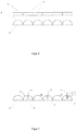
- Figure 1 shows a classic dipple tree ceiling comprising (from bottom to top) dipple trees 1, an original bed 2 and an original floor structure 3.
- the original floor structure 3 consists of bricks 3 which are placed on the original bed 2.
- the original floor structure 3 and the original fill are removed.
- selected dipple trees of the exposed dipple trees 1 are slit and the slit produced in the selected dipple tree is filled with an adhesive.
- a steel element is then inserted into the slot filled with adhesive before the adhesive hardens as a new system carrier.
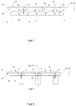
- Figure 2 illustrates this manufacturing process using a dipple tree top, a first selected dipple tree 5 being slotted on its top 8, in a second dipple tree 6 the slot 9 produced being filled with an adhesive 10 and in a third dipple tree 7 a steel element 11 as a new system carrier in the Adhesive 10 filled slot 9 is introduced.
- the steel element 11 contacts the slot surface with steel element partial areas, so that there is static friction between the steel element 11 and the third dipple tree 7. Under Overcoming this static friction and when the adhesive 10 has not solidified, the height of the steel element 11 can be aligned with the third dipple tree 7.
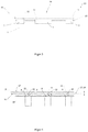
- Figure 3 shows a manufactured embodiment of the ceiling structure according to the invention.
- Selected dipple trees 5, 6, 7 are slotted on their surfaces, an adhesive 10 and a steel element 11 being introduced into the slits 9 produced.
- the steel elements 11 and the surfaces of the slots 9 are in frictional contact, so that the steel elements 11 can be aligned in their height relative to the respective dipple trees 5, 6, 7 while overcoming the frictional forces between the steel element 11 and the selected dipple tree 5, 6, 7, so that the upper edge 12 of the steel elements 11 form an altitude 13.
- a geometric plane 14 is formed by the upper edges 12 of the steel elements 11, which geometric plane 14 extends over a plurality of dipple trees 1 and above these dipple trees 1.
- the static elements of the ceiling structure namely the floor structure 15, the steel elements 11 and the wooden dipple trees 1 are structurally connected to one another, so that when the ceiling structure is stressed by bending, the wooden dipple trees 1 are subjected to tension and pressure, and the floor structure 15 is subjected to pressure.
- the steel elements 11 connecting the wooden dipple trees 1 and the floor construction 15 are subjected to thrust.
- the floor construction 15 is made of aluminum elements according to the prior art.
- the person skilled in the art recognizes that the ceiling construction according to the invention has a significantly lower weight than the original one in, inter alia, because the bed 2 is missing Figure 1 shown ceiling construction.
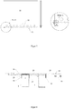
- Figure 4 shows a further embodiment of the ceiling construction according to the invention, which is based on a wooden tram ceiling according to the prior art.
- Wooden tram ceiling not shown, all elements are removed except for the wooden beams 1 and a board layer 18 resting on the wooden beams 1.
- the board layer 18 can be retained in the ceiling construction according to the invention for predominantly optical reasons, especially since the board layer 18 can have ornaments on its lower layer in existing ceilings.
- the wooden beams 1 comprise a slot 9, which slot 9 is partially filled with an adhesive 10. It is in each case a slot 9 in the case of non-hardening or non-hardening Adhesive 10 inserted a steel element 11.
- the steel elements 11 are aligned in their vertical position 13 with respect to the wooden beam 1 such that the upper edges 12 of the steel elements 11 define a geometric plane 14.
- the geometric plane 14 extends over a plurality of wooden beams 1 and runs above the wooden beams 1.
- Figure 5 shows a longitudinal section of the in Figure 4 Wood beam 1 shown in cross section.
- Several steel elements 1 are arranged distributed over the length of the wood beam 1.
- the steel elements 11 at the ends 20 of the wooden support 1 have a shorter length than the steel element 11 in the central area 19 of the wooden support 1.
- the wooden support 1 When the wooden support 1 is subjected to bending with a load that is uniform over the length of the wooden support, the wooden support 1 occurs in the central area 19 current teaching, the maximum of the bending load and, as a result, the maximum of the tensile and compressive forces (from the bending) and the maximum of the thrust forces.
- slot 9 in which slot 9 the steel element 11 is introduced in a form-fitting manner, extends over the board layer 18 and the wooden support 1.
- the slot 9 is made, for example, by means of a circular saw by sawing the board layer 18 and the wooden support. If necessary, the board layer 18 is previously attached to the wooden support 1.
- Figure 4 and Figure 5 show that the space between floor construction 15 and board layer 18 is designed as an air space.
- the specialist can also arrange an insulating material in this room.
- FIG. 6 shows a further embodiment of the ceiling construction according to the invention.
- the ceiling construction comprises existing, plastically deformed beams 1, which beams 1 have a compression zone and a tension zone under load.
- At least one steel element 11 is mechanically and / or adhesively connected to the surface of a carrier, the steel elements 11 comprising an adjusting element which is adjustable in height to form a horizontal geometric plane which extends over a plurality of carriers and above the carriers, which geometric plane 14 is defined by the highest edges 12 of the steel elements 11 in a punctiform and / or linear manner and is designed as a rigid construction of the floor articulated to the steel elements 11.
- Figure 7 shows a view and a sectional view of an embodiment of a steel element 11 with a rough surface in some areas.
- the steel element 11 has a serrated shape on its insertion edge 21 as a partial region of the surface of the steel element 11.
- the steel element 11 is by pressing the insertion surface 21 into a Figure 7 Pressed wooden tram 1, not shown.
- the user can provide a slot 9 in the wooden tram 1 for introducing the steel element 11 or create the slot 9 in the wooden tram 1 by pressing in the steel element 11.
- the rough surface of the steel element which in the Figure 7 Embodiment of the steel element 11 shown in the form of tines on the insertion edge 21 is used to increase the transmission of the thrust between the in Figure 7 Not shown wooden tram 1 and the steel element, since the teeth introduced into the wooden tram 1 act as an abutment.
- the steel element 11 further comprises bores 22 in the immediate vicinity of the insertion edge 21.
- the person skilled in the art can provide a slot 9 in the wooden tram 1 as described above before introducing the steel element 11 into the wooden tram 1.
- the person skilled in the art further fills the slot 9 with an adhesive and then brings it in Figure 7 Steel element 11 shown in the wooden tram 1.
- the still liquid adhesive extends through the bores 22 and solidifies as a body extending through the bores 22.
- the resulting positive connection further increases the maximum force to be transmitted between the steel element 11 and the wooden tram 1. This force can be taken into account in calculations as thrust.
- the adhesive which has not yet solidified can furthermore extend between the teeth on the insertion edge 21 and solidify as such a body. This also increases the maximum force that can be transmitted between the steel element 11 and the wooden tram 1, which force can be taken into account in calculations as the thrust force, by the positive engagement that occurs.
- Figure 8 partially shows a further embodiment of the ceiling construction according to the invention.
- the Figure 8 shows two beams 1, the upper edges of which have a different height level.
- the different altitude levels are illustrated by the altitude levels.
- the different height level of the upper edges can be caused, for example, by plastic deformation or by an imprecise laying of the supports 1 relative to one another.
- Steel elements 11 are arranged on the upper edge of the carrier 1, which upper edge forms part of the surface of the carrier 1, which steel elements 11 are connected to the carrier 1 by screws 23.
- screws 23 instead of the in Figure 8 screws 23 also provide other suitable connecting means for a mechanical and / or adhesive bond of a steel element 11 with a surface of a carrier 1.
- the height of the steel element 11 relative to the carrier 1 can be adjusted.
- the person skilled in the art can thus form a geometric plane 14, which is defined by the upper edge of the steel elements 11 and extends over a plurality of carriers 1, via the height adjustment of the steel elements 11.
- a person skilled in the art can insert wedges into a cavity between a beam 1 and a steel beam 11 for adjusting the height of the steel beams 11.
- Figure 9 shows a sectional view of a further embodiment of the ceiling construction according to the invention.
- the ceiling construction according to the invention is based on existing, plastically deformed beams 1, the upper edges of the beams 1 having different height levels, as shown in FIG Figure 9 is illustrated using the elevation.
- the carrier 1 each comprise a slot 9, which slot 9 is provided with an adhesive 1.
- a steel element 11 is introduced into each slot 9, a U-beam which is open at the bottom being connected as a further steel element 24 to the upper edge of the steel element.
- the introduction of the steel element 11 into the slot filled with adhesive takes place from the point of view of the production of a minimum adhesive surface between the steel element 11 and the adhesive and from the point of view of the production of a geometric plane 14, which plane 14 is defined by the upper edge of the further steel elements 24.
- the wooden beam 1 When the ceiling structure is subjected to bending, the wooden beam 1 can be loaded with a tensile force, while the further steel beam 24 is loaded with a compressive force.
- the rigid floor construction connected to the further steel beam 24 (in Figure 9 symbolized by level 14) prevents the other steel elements from buckling under pressure.
Landscapes
- Engineering & Computer Science (AREA)
- Architecture (AREA)
- Civil Engineering (AREA)
- Structural Engineering (AREA)
- Chemical Kinetics & Catalysis (AREA)
- Mechanical Engineering (AREA)
- Electrochemistry (AREA)
- Chemical & Material Sciences (AREA)
- Physics & Mathematics (AREA)
- Electromagnetism (AREA)
- Rod-Shaped Construction Members (AREA)
- Floor Finish (AREA)
- Conveying And Assembling Of Building Elements In Situ (AREA)
Applications Claiming Priority (1)
| Application Number | Priority Date | Filing Date | Title |
|---|---|---|---|
| ATA50578/2018A AT521425A1 (de) | 2018-07-04 | 2018-07-04 | Deckenkonstruktion |
Publications (3)
| Publication Number | Publication Date |
|---|---|
| EP3591130A1 true EP3591130A1 (fr) | 2020-01-08 |
| EP3591130C0 EP3591130C0 (fr) | 2023-07-12 |
| EP3591130B1 EP3591130B1 (fr) | 2023-07-12 |
Family
ID=66625835
Family Applications (1)
| Application Number | Title | Priority Date | Filing Date |
|---|---|---|---|
| EP19175583.4A Active EP3591130B1 (fr) | 2018-07-04 | 2019-05-21 | Structure de plafond |
Country Status (2)
| Country | Link |
|---|---|
| EP (1) | EP3591130B1 (fr) |
| AT (1) | AT521425A1 (fr) |
Citations (15)
| Publication number | Priority date | Publication date | Assignee | Title |
|---|---|---|---|---|
| DE63145C (de) | V. MÖBIUS in Oldisleben, Thüringen | Verfahren und Apparat zur Wiedergewinnung der Kohlensäure aus abgezapften Fässern und aus Flaschen oder Fässern, die vor dem Füllen mit Kohlensäure gefüllt sind | ||
| DE880939C (de) | 1940-11-02 | 1953-06-25 | Hoechst Ag | Verfahren zur Polymerisation ungesaettigter Verbindungen |
| DE3122431A1 (de) | 1980-06-05 | 1982-03-11 | Tuomo T. 33210 Tampere Poutanen | "verstaerkte platte und verfahren zu deren herstellung" |
| GB2134956A (en) | 1983-02-10 | 1984-08-22 | Rickards Timber Treatment Limi | Upgrading or restoring a timber beam |
| EP0269497A1 (fr) | 1986-11-04 | 1988-06-01 | Philippe Wolf | Renforcement d'éléments de charpente par insertion de plaques à haute résistance |
| EP0568441A1 (fr) * | 1992-04-28 | 1993-11-03 | Claude Marcel René Henri Blouet | Structure porteuse telle qu'un plancher, comprenant des poutres et une dalle béton et procédé pour son obtention |
| AT398797B (de) | 1990-09-13 | 1995-01-25 | Stracke Ing Markus | Verfahren zur unterstellungsfreien wiederherstellung der tragfähigkeit von altgeschossdecken bei gleichzeitiger verbesserung der wärmedämmung |
| FR2728293A1 (fr) | 1994-12-14 | 1996-06-21 | Brochard Francois Xavier | Perfectionnement aux dispositifs de renforcement des charpentes en bois |
| FR2760478A1 (fr) | 1997-03-06 | 1998-09-11 | Francois Aubert | Element de construction de type poutre |
| DE20316376U1 (de) | 2003-10-23 | 2004-02-26 | Bathon, Leander | Holz-Beton-Verbundsysteme aus Holzbauteilen, Zwischenschichten und Betonbauteilen |
| WO2004065713A1 (fr) * | 2003-01-23 | 2004-08-05 | Onesteel Reinforcing Pty Ltd | Systeme structurel de plancher |
| DE202006015693U1 (de) | 2005-10-14 | 2007-02-08 | Wey Modulbau Ag | Holz-Beton-Verbundelement |
| DE60310450T2 (de) | 2002-12-10 | 2007-03-29 | Jean-Luc Sandoz | Lärmschutzkonstruktion |
| DE202011005658U1 (de) * | 2011-04-28 | 2011-07-20 | Georg Ritter | System zur Sanierung von Fachwerkdecken |
| DE102017119096A1 (de) * | 2017-08-21 | 2019-02-21 | Deutsches Zentrum für Luft- und Raumfahrt e.V. | Holz-Beton-Verbunddecke |
Family Cites Families (4)
| Publication number | Priority date | Publication date | Assignee | Title |
|---|---|---|---|---|
| DE8804939U1 (de) * | 1988-04-14 | 1988-10-20 | Rheinhold & Mahla GmbH, 8000 München | Stahlprofil zur Sanierung von Holzbalkendecken |
| DE19808208A1 (de) * | 1998-02-27 | 1999-09-02 | Fischer Artur Werke Gmbh | Verbindungselement zum Verbinden von Holz und Beton |
| CN103195204A (zh) * | 2013-03-29 | 2013-07-10 | 苏州皇家整体住宅系统股份有限公司 | 木材-混凝土复合结构 |
| CZ2014901A3 (cs) * | 2014-12-12 | 2016-06-22 | Vysoká Škola Báňská - Technická Univerzita Ostrava | Spřahovací dílec pro dřevobetonovou stropní spřaženou konstrukci |
-
2018
- 2018-07-04 AT ATA50578/2018A patent/AT521425A1/de not_active Application Discontinuation
-
2019
- 2019-05-21 EP EP19175583.4A patent/EP3591130B1/fr active Active
Patent Citations (15)
| Publication number | Priority date | Publication date | Assignee | Title |
|---|---|---|---|---|
| DE63145C (de) | V. MÖBIUS in Oldisleben, Thüringen | Verfahren und Apparat zur Wiedergewinnung der Kohlensäure aus abgezapften Fässern und aus Flaschen oder Fässern, die vor dem Füllen mit Kohlensäure gefüllt sind | ||
| DE880939C (de) | 1940-11-02 | 1953-06-25 | Hoechst Ag | Verfahren zur Polymerisation ungesaettigter Verbindungen |
| DE3122431A1 (de) | 1980-06-05 | 1982-03-11 | Tuomo T. 33210 Tampere Poutanen | "verstaerkte platte und verfahren zu deren herstellung" |
| GB2134956A (en) | 1983-02-10 | 1984-08-22 | Rickards Timber Treatment Limi | Upgrading or restoring a timber beam |
| EP0269497A1 (fr) | 1986-11-04 | 1988-06-01 | Philippe Wolf | Renforcement d'éléments de charpente par insertion de plaques à haute résistance |
| AT398797B (de) | 1990-09-13 | 1995-01-25 | Stracke Ing Markus | Verfahren zur unterstellungsfreien wiederherstellung der tragfähigkeit von altgeschossdecken bei gleichzeitiger verbesserung der wärmedämmung |
| EP0568441A1 (fr) * | 1992-04-28 | 1993-11-03 | Claude Marcel René Henri Blouet | Structure porteuse telle qu'un plancher, comprenant des poutres et une dalle béton et procédé pour son obtention |
| FR2728293A1 (fr) | 1994-12-14 | 1996-06-21 | Brochard Francois Xavier | Perfectionnement aux dispositifs de renforcement des charpentes en bois |
| FR2760478A1 (fr) | 1997-03-06 | 1998-09-11 | Francois Aubert | Element de construction de type poutre |
| DE60310450T2 (de) | 2002-12-10 | 2007-03-29 | Jean-Luc Sandoz | Lärmschutzkonstruktion |
| WO2004065713A1 (fr) * | 2003-01-23 | 2004-08-05 | Onesteel Reinforcing Pty Ltd | Systeme structurel de plancher |
| DE20316376U1 (de) | 2003-10-23 | 2004-02-26 | Bathon, Leander | Holz-Beton-Verbundsysteme aus Holzbauteilen, Zwischenschichten und Betonbauteilen |
| DE202006015693U1 (de) | 2005-10-14 | 2007-02-08 | Wey Modulbau Ag | Holz-Beton-Verbundelement |
| DE202011005658U1 (de) * | 2011-04-28 | 2011-07-20 | Georg Ritter | System zur Sanierung von Fachwerkdecken |
| DE102017119096A1 (de) * | 2017-08-21 | 2019-02-21 | Deutsches Zentrum für Luft- und Raumfahrt e.V. | Holz-Beton-Verbunddecke |
Also Published As
| Publication number | Publication date |
|---|---|
| EP3591130C0 (fr) | 2023-07-12 |
| AT521425A1 (de) | 2020-01-15 |
| EP3591130B1 (fr) | 2023-07-12 |
Similar Documents
| Publication | Publication Date | Title |
|---|---|---|
| EP1007809B1 (fr) | Dispositif de renfort pour structures porteuses | |
| EP3695062B1 (fr) | Élément d'ancrage, pièce en béton pourvue d'un élément d'ancrage et procédé de fabrication | |
| EP3426857B1 (fr) | Élément de construction en béton armé | |
| EP0059171B1 (fr) | Boulon et canon pour la prise et la transmission d'une force transversale | |
| EP2821562B1 (fr) | Structure composite en bois/béton | |
| DE19828607A1 (de) | Verfahren zum Verstärken von Stahl- und Spannbetonbauteilen | |
| EP2821561B1 (fr) | Elément de construction en bois et structure composite en bois/béton | |
| EP2715013A1 (fr) | Ensemble d'assemblage et procédé de production d'une consolidation contre la perforation, d'un renfort de force transversale supplémentaire ou d'un raccordement d'armature | |
| AT520303B1 (de) | Verfahren zur herstellung von verbunddecken | |
| DE102019215009A1 (de) | Holz-Beton-Verbundplatte, insbesondere zum Einsatz als Gebäude-Decken- oder -Wandplatte und Verfahren zu deren Herstellung | |
| EP2481858A1 (fr) | Procédé de fixation d'un élément d'ancrage sur une partie de construction et application du procédé | |
| DE602004010196T2 (de) | Baurahmenprofil | |
| EP3591130B1 (fr) | Structure de plafond | |
| EP3546666A1 (fr) | Module de raccordement bois-béton | |
| DE1484009A1 (de) | Haus in Fertigbauweise,plattenfoermiges Bauelement zur Herstellung dieses Hauses,Zwischenstueck zur Verbindung der Bauelemente und Verfahren zur Herstellung des Hauses | |
| DE102018112634A1 (de) | Fugenprofil | |
| AT507180B1 (de) | Baukonstruktion mit im winkel zueinander angeordneten tragelementen | |
| DE10133976A1 (de) | Kraftübertragende Verbindung von Bauteilen, insb. von Bauteilen aus Holz, mittels Klebeverbindung | |
| DE102021003062B4 (de) | Ankernagel für Faserwolle-Dämmmatten | |
| DE3000154A1 (de) | Vorrichtung und verfahren zur eintragung von lasten in bestehende stahl- und spannbetonbauteile | |
| DE20121917U1 (de) | Kraftübertragende Verbindung von Bauteilen, insbesondere von Bauteilen aus Holz, mittels Klebeverbindung | |
| DE202018102948U1 (de) | Fugenprofil | |
| CH700137A1 (de) | Biegeträger-verbundelement aus holz und faserverstärktem kunststoff. | |
| EP0985779A2 (fr) | Pannneau de mur porteur pour une construction en bois | |
| DE102017005744A1 (de) | Verfahren und Vorrichtung zum Verankern von Bauteilen |
Legal Events
| Date | Code | Title | Description |
|---|---|---|---|
| PUAI | Public reference made under article 153(3) epc to a published international application that has entered the european phase |
Free format text: ORIGINAL CODE: 0009012 |
|
| STAA | Information on the status of an ep patent application or granted ep patent |
Free format text: STATUS: THE APPLICATION HAS BEEN PUBLISHED |
|
| AK | Designated contracting states |
Kind code of ref document: A1 Designated state(s): AL AT BE BG CH CY CZ DE DK EE ES FI FR GB GR HR HU IE IS IT LI LT LU LV MC MK MT NL NO PL PT RO RS SE SI SK SM TR |
|
| AX | Request for extension of the european patent |
Extension state: BA ME |
|
| STAA | Information on the status of an ep patent application or granted ep patent |
Free format text: STATUS: REQUEST FOR EXAMINATION WAS MADE |
|
| 17P | Request for examination filed |
Effective date: 20200624 |
|
| RBV | Designated contracting states (corrected) |
Designated state(s): AL AT BE BG CH CY CZ DE DK EE ES FI FR GB GR HR HU IE IS IT LI LT LU LV MC MK MT NL NO PL PT RO RS SE SI SK SM TR |
|
| STAA | Information on the status of an ep patent application or granted ep patent |
Free format text: STATUS: EXAMINATION IS IN PROGRESS |
|
| 17Q | First examination report despatched |
Effective date: 20220531 |
|
| GRAP | Despatch of communication of intention to grant a patent |
Free format text: ORIGINAL CODE: EPIDOSNIGR1 |
|
| STAA | Information on the status of an ep patent application or granted ep patent |
Free format text: STATUS: GRANT OF PATENT IS INTENDED |
|
| INTG | Intention to grant announced |
Effective date: 20230131 |
|
| GRAS | Grant fee paid |
Free format text: ORIGINAL CODE: EPIDOSNIGR3 |
|
| GRAA | (expected) grant |
Free format text: ORIGINAL CODE: 0009210 |
|
| STAA | Information on the status of an ep patent application or granted ep patent |
Free format text: STATUS: THE PATENT HAS BEEN GRANTED |
|
| AK | Designated contracting states |
Kind code of ref document: B1 Designated state(s): AL AT BE BG CH CY CZ DE DK EE ES FI FR GB GR HR HU IE IS IT LI LT LU LV MC MK MT NL NO PL PT RO RS SE SI SK SM TR |
|
| P01 | Opt-out of the competence of the unified patent court (upc) registered |
Effective date: 20230606 |
|
| REG | Reference to a national code |
Ref country code: CH Ref legal event code: EP |
|
| REG | Reference to a national code |
Ref country code: DE Ref legal event code: R096 Ref document number: 502019008462 Country of ref document: DE |
|
| REG | Reference to a national code |
Ref country code: IE Ref legal event code: FG4D Free format text: LANGUAGE OF EP DOCUMENT: GERMAN |
|
| U01 | Request for unitary effect filed |
Effective date: 20230802 |
|
| U07 | Unitary effect registered |
Designated state(s): AT BE BG DE DK EE FI FR IT LT LU LV MT NL PT SE SI Effective date: 20230808 |
|
| P04 | Withdrawal of opt-out of the competence of the unified patent court (upc) registered |
Effective date: 20230804 |
|
| REG | Reference to a national code |
Ref country code: LT Ref legal event code: MG9D |
|
| PG25 | Lapsed in a contracting state [announced via postgrant information from national office to epo] |
Ref country code: GR Free format text: LAPSE BECAUSE OF FAILURE TO SUBMIT A TRANSLATION OF THE DESCRIPTION OR TO PAY THE FEE WITHIN THE PRESCRIBED TIME-LIMIT Effective date: 20231013 |
|
| PG25 | Lapsed in a contracting state [announced via postgrant information from national office to epo] |
Ref country code: ES Free format text: LAPSE BECAUSE OF FAILURE TO SUBMIT A TRANSLATION OF THE DESCRIPTION OR TO PAY THE FEE WITHIN THE PRESCRIBED TIME-LIMIT Effective date: 20230712 |
|
| PG25 | Lapsed in a contracting state [announced via postgrant information from national office to epo] |
Ref country code: IS Free format text: LAPSE BECAUSE OF FAILURE TO SUBMIT A TRANSLATION OF THE DESCRIPTION OR TO PAY THE FEE WITHIN THE PRESCRIBED TIME-LIMIT Effective date: 20231112 |
|
| PG25 | Lapsed in a contracting state [announced via postgrant information from national office to epo] |
Ref country code: RS Free format text: LAPSE BECAUSE OF FAILURE TO SUBMIT A TRANSLATION OF THE DESCRIPTION OR TO PAY THE FEE WITHIN THE PRESCRIBED TIME-LIMIT Effective date: 20230712 Ref country code: NO Free format text: LAPSE BECAUSE OF FAILURE TO SUBMIT A TRANSLATION OF THE DESCRIPTION OR TO PAY THE FEE WITHIN THE PRESCRIBED TIME-LIMIT Effective date: 20231012 Ref country code: IS Free format text: LAPSE BECAUSE OF FAILURE TO SUBMIT A TRANSLATION OF THE DESCRIPTION OR TO PAY THE FEE WITHIN THE PRESCRIBED TIME-LIMIT Effective date: 20231112 Ref country code: HR Free format text: LAPSE BECAUSE OF FAILURE TO SUBMIT A TRANSLATION OF THE DESCRIPTION OR TO PAY THE FEE WITHIN THE PRESCRIBED TIME-LIMIT Effective date: 20230712 Ref country code: GR Free format text: LAPSE BECAUSE OF FAILURE TO SUBMIT A TRANSLATION OF THE DESCRIPTION OR TO PAY THE FEE WITHIN THE PRESCRIBED TIME-LIMIT Effective date: 20231013 Ref country code: ES Free format text: LAPSE BECAUSE OF FAILURE TO SUBMIT A TRANSLATION OF THE DESCRIPTION OR TO PAY THE FEE WITHIN THE PRESCRIBED TIME-LIMIT Effective date: 20230712 |
|
| PG25 | Lapsed in a contracting state [announced via postgrant information from national office to epo] |
Ref country code: PL Free format text: LAPSE BECAUSE OF FAILURE TO SUBMIT A TRANSLATION OF THE DESCRIPTION OR TO PAY THE FEE WITHIN THE PRESCRIBED TIME-LIMIT Effective date: 20230712 |
|
| REG | Reference to a national code |
Ref country code: DE Ref legal event code: R097 Ref document number: 502019008462 Country of ref document: DE |
|
| PG25 | Lapsed in a contracting state [announced via postgrant information from national office to epo] |
Ref country code: SM Free format text: LAPSE BECAUSE OF FAILURE TO SUBMIT A TRANSLATION OF THE DESCRIPTION OR TO PAY THE FEE WITHIN THE PRESCRIBED TIME-LIMIT Effective date: 20230712 Ref country code: RO Free format text: LAPSE BECAUSE OF FAILURE TO SUBMIT A TRANSLATION OF THE DESCRIPTION OR TO PAY THE FEE WITHIN THE PRESCRIBED TIME-LIMIT Effective date: 20230712 Ref country code: CZ Free format text: LAPSE BECAUSE OF FAILURE TO SUBMIT A TRANSLATION OF THE DESCRIPTION OR TO PAY THE FEE WITHIN THE PRESCRIBED TIME-LIMIT Effective date: 20230712 Ref country code: SK Free format text: LAPSE BECAUSE OF FAILURE TO SUBMIT A TRANSLATION OF THE DESCRIPTION OR TO PAY THE FEE WITHIN THE PRESCRIBED TIME-LIMIT Effective date: 20230712 |
|
| U20 | Renewal fee for the european patent with unitary effect paid |
Year of fee payment: 6 Effective date: 20240321 |
|
| PLBE | No opposition filed within time limit |
Free format text: ORIGINAL CODE: 0009261 |
|
| STAA | Information on the status of an ep patent application or granted ep patent |
Free format text: STATUS: NO OPPOSITION FILED WITHIN TIME LIMIT |
|
| 26N | No opposition filed |
Effective date: 20240415 |
|
| PGFP | Annual fee paid to national office [announced via postgrant information from national office to epo] |
Ref country code: GB Payment date: 20240521 Year of fee payment: 6 |
|
| PGFP | Annual fee paid to national office [announced via postgrant information from national office to epo] |
Ref country code: CH Payment date: 20240602 Year of fee payment: 6 |
|
| P05 | Withdrawal of opt-out of the competence of the unified patent court (upc) changed |
Free format text: CASE NUMBER: APP_559158/2023 Effective date: 20230808 |
|
| PG25 | Lapsed in a contracting state [announced via postgrant information from national office to epo] |
Ref country code: MC Free format text: LAPSE BECAUSE OF FAILURE TO SUBMIT A TRANSLATION OF THE DESCRIPTION OR TO PAY THE FEE WITHIN THE PRESCRIBED TIME-LIMIT Effective date: 20230712 |
|
| PG25 | Lapsed in a contracting state [announced via postgrant information from national office to epo] |
Ref country code: MC Free format text: LAPSE BECAUSE OF FAILURE TO SUBMIT A TRANSLATION OF THE DESCRIPTION OR TO PAY THE FEE WITHIN THE PRESCRIBED TIME-LIMIT Effective date: 20230712 |
|
| U20 | Renewal fee for the european patent with unitary effect paid |
Year of fee payment: 7 Effective date: 20250304 |
|
| PG25 | Lapsed in a contracting state [announced via postgrant information from national office to epo] |
Ref country code: IE Free format text: LAPSE BECAUSE OF NON-PAYMENT OF DUE FEES Effective date: 20240521 |
|
| PG25 | Lapsed in a contracting state [announced via postgrant information from national office to epo] |
Ref country code: CY Free format text: LAPSE BECAUSE OF FAILURE TO SUBMIT A TRANSLATION OF THE DESCRIPTION OR TO PAY THE FEE WITHIN THE PRESCRIBED TIME-LIMIT; INVALID AB INITIO Effective date: 20190521 |
|
| PG25 | Lapsed in a contracting state [announced via postgrant information from national office to epo] |
Ref country code: HU Free format text: LAPSE BECAUSE OF FAILURE TO SUBMIT A TRANSLATION OF THE DESCRIPTION OR TO PAY THE FEE WITHIN THE PRESCRIBED TIME-LIMIT; INVALID AB INITIO Effective date: 20190521 |
|
| REG | Reference to a national code |
Ref country code: CH Ref legal event code: H13 Free format text: ST27 STATUS EVENT CODE: U-0-0-H10-H13 (AS PROVIDED BY THE NATIONAL OFFICE) Effective date: 20251223 |
|
| PG25 | Lapsed in a contracting state [announced via postgrant information from national office to epo] |
Ref country code: CH Free format text: LAPSE BECAUSE OF NON-PAYMENT OF DUE FEES Effective date: 20250531 |
|
| GBPC | Gb: european patent ceased through non-payment of renewal fee |
Effective date: 20250521 |
|
| PG25 | Lapsed in a contracting state [announced via postgrant information from national office to epo] |
Ref country code: GB Free format text: LAPSE BECAUSE OF NON-PAYMENT OF DUE FEES Effective date: 20250521 |
|
| U20 | Renewal fee for the european patent with unitary effect paid |
Year of fee payment: 8 Effective date: 20260324 |