EP3594028B1 - Ensemble de verrouillage rotatif pour augmenter et réduire la hauteur d'un véhicule - Google Patents
Ensemble de verrouillage rotatif pour augmenter et réduire la hauteur d'un véhicule Download PDFInfo
- Publication number
- EP3594028B1 EP3594028B1 EP19173770.9A EP19173770A EP3594028B1 EP 3594028 B1 EP3594028 B1 EP 3594028B1 EP 19173770 A EP19173770 A EP 19173770A EP 3594028 B1 EP3594028 B1 EP 3594028B1
- Authority
- EP
- European Patent Office
- Prior art keywords
- lift housing
- center axis
- latch assembly
- inner ring
- support tube
- Prior art date
- Legal status (The legal status is an assumption and is not a legal conclusion. Google has not performed a legal analysis and makes no representation as to the accuracy of the status listed.)
- Active
Links
Images




Classifications
-
- B—PERFORMING OPERATIONS; TRANSPORTING
- B60—VEHICLES IN GENERAL
- B60G—VEHICLE SUSPENSION ARRANGEMENTS
- B60G11/00—Resilient suspensions characterised by arrangement, location or kind of springs
- B60G11/14—Resilient suspensions characterised by arrangement, location or kind of springs having helical, spiral or coil springs only
- B60G11/16—Resilient suspensions characterised by arrangement, location or kind of springs having helical, spiral or coil springs only characterised by means specially adapted for attaching the spring to axle or sprung part of the vehicle
-
- B—PERFORMING OPERATIONS; TRANSPORTING
- B60—VEHICLES IN GENERAL
- B60G—VEHICLE SUSPENSION ARRANGEMENTS
- B60G15/00—Resilient suspensions characterised by arrangement, location or type of combined spring and vibration damper, e.g. telescopic type
- B60G15/02—Resilient suspensions characterised by arrangement, location or type of combined spring and vibration damper, e.g. telescopic type having mechanical spring
- B60G15/06—Resilient suspensions characterised by arrangement, location or type of combined spring and vibration damper, e.g. telescopic type having mechanical spring and fluid damper
-
- B—PERFORMING OPERATIONS; TRANSPORTING
- B60—VEHICLES IN GENERAL
- B60G—VEHICLE SUSPENSION ARRANGEMENTS
- B60G17/00—Resilient suspensions having means for adjusting the spring or vibration-damper characteristics, for regulating the distance between a supporting surface and a sprung part of vehicle or for locking suspension during use to meet varying vehicular or surface conditions, e.g. due to speed or load
- B60G17/005—Suspension locking arrangements
-
- B—PERFORMING OPERATIONS; TRANSPORTING
- B60—VEHICLES IN GENERAL
- B60G—VEHICLE SUSPENSION ARRANGEMENTS
- B60G17/00—Resilient suspensions having means for adjusting the spring or vibration-damper characteristics, for regulating the distance between a supporting surface and a sprung part of vehicle or for locking suspension during use to meet varying vehicular or surface conditions, e.g. due to speed or load
- B60G17/015—Resilient suspensions having means for adjusting the spring or vibration-damper characteristics, for regulating the distance between a supporting surface and a sprung part of vehicle or for locking suspension during use to meet varying vehicular or surface conditions, e.g. due to speed or load the regulating means comprising electric or electronic elements
- B60G17/0152—Resilient suspensions having means for adjusting the spring or vibration-damper characteristics, for regulating the distance between a supporting surface and a sprung part of vehicle or for locking suspension during use to meet varying vehicular or surface conditions, e.g. due to speed or load the regulating means comprising electric or electronic elements characterised by the action on a particular type of suspension unit
- B60G17/0157—Resilient suspensions having means for adjusting the spring or vibration-damper characteristics, for regulating the distance between a supporting surface and a sprung part of vehicle or for locking suspension during use to meet varying vehicular or surface conditions, e.g. due to speed or load the regulating means comprising electric or electronic elements characterised by the action on a particular type of suspension unit non-fluid unit, e.g. electric motor
-
- B—PERFORMING OPERATIONS; TRANSPORTING
- B60—VEHICLES IN GENERAL
- B60G—VEHICLE SUSPENSION ARRANGEMENTS
- B60G17/00—Resilient suspensions having means for adjusting the spring or vibration-damper characteristics, for regulating the distance between a supporting surface and a sprung part of vehicle or for locking suspension during use to meet varying vehicular or surface conditions, e.g. due to speed or load
- B60G17/02—Spring characteristics, e.g. mechanical springs and mechanical adjusting means
- B60G17/021—Spring characteristics, e.g. mechanical springs and mechanical adjusting means the mechanical spring being a coil spring
-
- B—PERFORMING OPERATIONS; TRANSPORTING
- B60—VEHICLES IN GENERAL
- B60G—VEHICLE SUSPENSION ARRANGEMENTS
- B60G2202/00—Indexing codes relating to the type of spring, damper or actuator
- B60G2202/40—Type of actuator
- B60G2202/42—Electric actuator
-
- B—PERFORMING OPERATIONS; TRANSPORTING
- B60—VEHICLES IN GENERAL
- B60G—VEHICLE SUSPENSION ARRANGEMENTS
- B60G2202/00—Indexing codes relating to the type of spring, damper or actuator
- B60G2202/40—Type of actuator
- B60G2202/44—Axial actuator, e.g. telescopic
- B60G2202/441—Axial actuator, e.g. telescopic where axial movement is translated to rotation of the connected end part
-
- B—PERFORMING OPERATIONS; TRANSPORTING
- B60—VEHICLES IN GENERAL
- B60G—VEHICLE SUSPENSION ARRANGEMENTS
- B60G2204/00—Indexing codes related to suspensions per se or to auxiliary parts
- B60G2204/40—Auxiliary suspension parts; Adjustment of suspensions
- B60G2204/44—Centering or positioning means
-
- B—PERFORMING OPERATIONS; TRANSPORTING
- B60—VEHICLES IN GENERAL
- B60G—VEHICLE SUSPENSION ARRANGEMENTS
- B60G2204/00—Indexing codes related to suspensions per se or to auxiliary parts
- B60G2204/40—Auxiliary suspension parts; Adjustment of suspensions
- B60G2204/46—Means for locking the suspension
-
- B—PERFORMING OPERATIONS; TRANSPORTING
- B60—VEHICLES IN GENERAL
- B60G—VEHICLE SUSPENSION ARRANGEMENTS
- B60G2204/00—Indexing codes related to suspensions per se or to auxiliary parts
- B60G2204/40—Auxiliary suspension parts; Adjustment of suspensions
- B60G2204/46—Means for locking the suspension
- B60G2204/4604—Means for locking the suspension mechanically, e.g. using a hook as anticreep mechanism
-
- B—PERFORMING OPERATIONS; TRANSPORTING
- B60—VEHICLES IN GENERAL
- B60G—VEHICLE SUSPENSION ARRANGEMENTS
- B60G2500/00—Indexing codes relating to the regulated action or device
- B60G2500/20—Spring action or springs
- B60G2500/22—Spring constant
-
- B—PERFORMING OPERATIONS; TRANSPORTING
- B60—VEHICLES IN GENERAL
- B60G—VEHICLE SUSPENSION ARRANGEMENTS
- B60G2500/00—Indexing codes relating to the regulated action or device
- B60G2500/30—Height or ground clearance
Definitions
- the present invention generally relates to a rotating latch assembly for raising and lowering the height of a vehicle.
- the devices may be provided in the suspension struts of motor vehicles, in particular, for increasing the ground clearance of motor vehicles or lowering the body for flat road surfaces.
- a device typically includes a lift housing disposed on a center axis defining a chamber.
- a support tube is disposed in the chamber with the lift housing being movable along the center axis relative to the support tube.
- the movement of the lift housing is typically conducted using a hydraulic actuator.
- Solenoid activated mechanisms e.g. a pneumatic suspension are also available for this type of application.
- the solenoid activated mechanisms require electric power input for the locking/unlocking of the solenoid valve which cumulates with the required hydraulic power.
- the device includes a lift housing disposed on a center axis and extending between a first opened end and a second opened end and defining a chamber extending therebetween.
- a support tube is slidably disposed in the chamber and extending between a first end and a second end. The first end is disposed outside of the chamber and axially spaced from the first opened end. The second end of the support tube is disposed outside of the chamber and axially spaced from the second opened end.
- the lift housing is movable along the support tube between an extended position and a lowered position in response to a movement provided by an actuator.
- the extended position is defined as the lift housing being adjacent to the first end for raising the height of the vehicle.
- the lowered position is defined as the lift housing being adjacent to the second end for lowering the height of the vehicle.
- Document DE 102014215420 A1 discloses a device for height adjustment of a vehicle body.
- the invention relates to a device for adjusting the height of a vehicle body comprising a movement thread arranged between the vehicle body and a wheel carrier and displacing two components displaceable relative to one another between an upper and a lower adjustment position, with a movement thread with the first component axially non-displaceably connected, electromotively driven spindle and a spindle nut which is accommodated in a rotationally fixed and axially displaceable manner on the spindle and is axially non-displaceably connected to the second component.
- a switchable, axially effective form-fit which mechanically bridges the movement thread is provided at least at the upper adjustment position between the components.
- the invention discloses a suspension-lifting adjusting device according to the preamble of claim 1.
- the invention discloses a suspension-lifting adjusting device.
- the suspension-lifting adjusting device comprises: a drive component, wherein the drive component comprises a worm wheel and a worm, and the worm is meshed with the worm wheel; a transfer component, wherein the transfer component is connected with the worm wheel; a first lock component, wherein the first lock component is matched with the transfer component to make the spring bottom seat move along up-down direction among a plurality of setting positions and make the spring bottom seat locked in one position of setting positions.
- the position of the car body is adjusted by adjusting the position of the spring bottom seat in up-down direction, which has the advantages of being fixed in the force-bearing point of absorber, simple in structure, low in manufacturing cost and wide in range of application.
- Document DE102015224862 A1 discloses a linear actuator and a device for height adjustment of a vehicle body with such a linear actuator.
- This linear actuator is provided with a lifting device, the first lifting part and second lifting part of which are displaceable relative to one another along a lifting axis, and with a lifting device at several axial positions positively bridging locking device, the locking element of which has a slide track and locking stops arranged in the axial positions, and with a stop element which is pivotable about the lifting axis and which has at least one along the slide track has movable cams for interacting with the locking stops, each of these cams being provided with an endless link track and the locking stops in these axial positions.
- the present invention provides for a rotating latch assembly that efficiently raises and lowers the height of the vehicle thereby improving vehicle energy consumption due to reduced air drag.
- the present invention maintains the vehicle being in the raised position without additional energy consumption.
- the present invention prevents unintentional movements of the rotating latch assembly from the extended position to the lowered position.
- the rotating latch assembly includes a lift housing disposed on a center axis and extending between a first opened end and a second opened end and defining a chamber extending therebetween.
- a support tube is slidably disposed in the chamber and extends between a first end and a second end. The first end is disposed outside of the chamber and axially spaced from the first opened end. The second end of the support tube is disposed outside of the chamber and axially spaced from the second opened end.
- the lift housing is movable along the support tube between an extended position and a lowered position in response to a movement provided by an actuator.
- the extended position is defined as the lift housing being adjacent to the first end for raising the height of the vehicle.
- the lowered position is defined as the lift housing being adjacent to the second end for lowering the height of the vehicle.
- a retaining member is disposed between the lift housing and the support tube and attached to the support tube and the lift housing for maintaining the lift housing in the extended position as the lift housing moving from the lowered position to the extended position and allowing the lift housing to move from the extended position to the lowered position, wherein said retaining member includes an inner ring and an outer ring with said inner ring being attached to said support tube and said outer ring being attached to said lift housing, wherein said inner ring is disposed between said support tube and said lift housing, extending between a lower end and an upper end, and has an interior surface and an exterior surface with said interior surface and said exterior surface extending about the center axis between said lower end and said upper end, wherein the rotating latch assembly includes a plurality of inner ring teeth circumferentially spaced from one another, extending radially outward
- the rotating latch assembly includes a lift housing disposed on a center axis extending between a first opened end and a second opened end and defining a chamber extending therebetween.
- a support tube is slidably disposed in the chamber and extending between a first end and a second end. The first end is disposed outside of the chamber and axially spaced from the first opened end. The second end of the support tube is disposed outside of the chamber and axially spaced from the second opened end.
- a projection is disposed in the chamber and extends radially outwardly from the support tube to a distal end for engaging the lift housing.
- a protrusion is disposed in the chamber and adjacent to the second opened end extending radially inwardly from the lift housing and toward the center axis for engaging the projection to allow the lift housing to move axially along the support tube between an extended position and a lowered position in response to a movement provided by an actuator.
- the extended position is defined as the lift housing being adjacent to the first end for raising the height of the vehicle.
- the lowered position is defined as the lift housing being adjacent to the second end for lowering the height of the vehicle.
- a retaining member is disposed between the lift housing and the support tube and attached to the support tube and the lift housing for maintaining the lift housing in the extended position as the lift housing moving from the lowered position to the extended position and allowing the lift housing to move from the extended position to the lowered position.
- a rotating latch assembly 20 constructed in accordance with one embodiment of the present invention is generally shown in Figure 1 .
- the rotating latch assembly 20 is used in a vehicle for raising and lowering the height of the vehicle.
- the rotating latch assembly 20 includes a lift housing 22, having a generally tubular shape, disposed annularly about and extending along a center axis A between a first opened end 24 and a second opened end 26.
- the lift housing 22 defines a chamber 28 extending along the center axis A between the first opened end 24 and the second opened end 26.
- a lift springs seat 29 is disposed about the first opened end 24 of the lift housing 22 and extends annularly about the center axis A.
- a support tube 30, having a generally cylindrical shape, is disposed in the chamber 28 of the lift housing 22. The support tube 30 extends about the center axis A between a first end 32 and a second end 34.
- the support tube 30 is slidable along the center axis A in the chamber 28 with respect to the lift housing 22.
- the first end 32 of the support tube 30 is disposed outside of the chamber 28 and spaced from the first opened end 24.
- the second end 34 of the support tube 30 is also disposed outside of the chamber 28 and spaced from the second opened end 26.
- the lift housing 22 can be connected to an actuator, e.g. a hydraulic actuator, for moving the lift housing 22 axially along the support tube 30.
- the support tube 30 includes a first portion 36 and a second portion 38.
- the first portion 36 of the support tube is disposed adjacent to the first end 32 and extends about the center axis A to define a first diameter D 1 .
- the second portion 38 of the support tube 30 is spaced from the first portion 36, disposed adjacent to the second end 34, and extends about the center axis A to define a second diameter D 2 with the second diameter D 2 being greater than the first diameter D 1 .
- the first portion 36 of the support tube 30 is narrower than the second portion 38 of the support tube 30.
- An intermediate portion 40 extends between the first portion 36 and the second portion 38 to connect the first portion 36 with the second portion 38.
- the intermediate portion 40 extends radially outwardly from the first portion 36, perpendicular to the center axis A, to the second portion 38 to connect the first portion 36 with the second portion 38 and define a shoulder 42 extending along the intermediate portion 40.
- the intermediate portion 40 and the lift housing 22 defines a compartment 44 extending between the shoulder 42, the first portion 36 of the support tube 30, and the lift housing 22.
- the intermediate portion 40 includes a projection 46, disposed in the chamber 28, extending radially outwardly from the intermediate portion 40, and perpendicular to the center axis A, to a distal end 48 for engaging the lift housing 22.
- the lift housing 22 includes a protrusion 50, disposed in the chamber 28 and adjacent to the second end 26, extending radially inwardly toward the center axis A for engaging the projection 46 of the intermediate portion 40 to allow the lift housing 22 to move axially along the support tube 30 between an extended position and a lowered position in response to the axial movement provided by the actuator.
- the projection 46 and the protrusion 50 When in the extended position, as illustrated in Figure 2 , the projection 46 and the protrusion 50 are in an abutment relationship with one another for raising the height of the vehicle. In the lowered position, as illustrated in Figure 3 , the projection 46 and the protrusion 50 is axially spaced from one another for lowering the height of the vehicle.
- a retaining member 52 is disposed in the compartment 44, attached to the support tube 30 and the lift housing 22, for maintaining the lift housing 22 in the extended position as the lift housing 22 is moving from the lowered position to the extended position and allowing the lift housing 22 to move from the extended position to the lowered position.
- the retaining member 52 includes an inner ring 54 and an outer ring 56 with the inner ring 54 being attached to the support tube 30 and the outer ring 56 being attached to the lift housing 22.
- the inner ring 54 and the outer ring 56 engage one another and are rotatable relative to one another for translating the axial movement of the lift housing 22 into a rotational movement to allow the lift housing 22 to be maintained in the extended position and allow the lift housing 22 to be moved from the extended position to the lowered position.
- the inner ring 54 having a generally cylindrical shape, is disposed in the compartment 44 extending between a lower end 58 and an upper end 60.
- the lower end 58 of the inner ring 54 is disposed in abutment relationship with the shoulder 42.
- the inner ring 54 has an interior surface 62 and an exterior surface 64 both extending annularly about the center axis A and between the lower end 58 and the upper end 60.
- a bushing 65 having a generally cylindrical shape, is disposed between the interior surface 62 and the first portion 36 of the support tube 30. The bushing 65 is attached to the first portion 36 of the support tube 30, e.g.
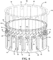
- a plurality of inner ring teeth 66 circumferentially spaced from one another, extends radially outwardly from the exterior surface 64 of the inner ring 54, along the center axis A, to a terminal end 68 spaced from the upper end 60 and defining a plurality of slots 70 between the adjacent inner ring teeth 66, circumferentially spaced from one another, and extending along the center axis A.
- the exterior surface 64 of the inner ring 54 defines a pathway 76 extending radially inwardly toward the center axis A and sinusoidally about the inner ring 54. As best illustrated in Figures 5-8 , the pathway 76 defines a plurality of peaks 78 and troughs 80.
- the exterior surface 64 of the inner ring 54 further defines a plurality of channels 82, circumferentially spaced from one another, extending parallel to the slots 70 and connected to the pathway 76.
- the peaks 78 of the pathway 76 are offset from the terminal end 68 of the inner ring teeth 66.
- the troughs 80 are in alignment with the nadir 74 and are connected to the channels 82.
- the pathway 76 can include three different position, e.g. the extended position, a raised position, and the lowered position. It should also be appreciated that an external position control needs to be used to control cycle and the position of the outer ring 56.
- the outer ring 56 having a generally circular shape, is disposed in the compartment 44 and extends between a top end 84 and a bottom end 86.
- the outer ring 56 also has an inner surface 88 and an outer surface 90.
- the inner surface 88 and the outer surface 90 extend about the center axis A between the top end 84 and the bottom end 86 with the top end 84 being attached to the lift housing 22 for engaging the inner ring 54.
- the inner surface 88 of the outer ring 56 includes a plurality of outer ring teeth 92, circumferentially spaced from one another, extending radially outwardly from the inner surface 88 of the outer ring 56, along the center axis A, and tapering to a primary end 94 for engaging the nadir 74 in the extended position.
- This feature allows the lift housing 22 to be locked in the extended position without additional input from the hydraulic actuator.
- the primary end 94 being disposed in the cavity 72 in the extended position prevents any unintentional movements of the lift housing 22 from the extended position to the lowered position.
- the outer ring 56 includes a plurality of nubs 96 disposed at the primary end 94 of the outer ring teeth 92 and extending radially inwardly toward the center axis A to engage the pathway 76 and the channel 82 to allow the lift housing 22 to move between the extended position and the lowered position.
- a stop ring 98 having a generally circular shape, disposed in the compartment 44, adjacent to the bushing 65.
- the stop ring 98 includes a plurality of lips 100, circumferentially spaced from one another, extending radially outwardly from the stop ring 98 and defining a plurality of gap 102 disposed between the adjacent lips 100 for receiving the outer ring teeth and limits the movement of the outer ring teeth 92.
- the lift housing 22 moves along the center axis A and the support tube 30 from the lowered position. While in the lowered position, the outer ring teeth 92 are received in the slots 70 between the inner ring teeth 66.
- the nubs 96 of the outer ring 56 slides along the channels 82 to the pathway 76.
- the axial movement provided by the hydraulic actuator is converted to a rotational movement thereby rotating the inner ring 54 about the center axis A.
- the outer ring teeth 92 aligns with the inner ring teeth 66 allowing the primary end 94 of the outer ring teeth 92 to be received in the cavity 72 of the inner ring teeth 66 thereby defining the extended position to increase the height of the vehicle.
- the outer ring teeth 92 is rested in the cavity 72 of the inner ring teeth 66 thereby maintaining the lift housing 22 in the extended position without any additional force input provided by the hydraulic actuator.
- the hydraulic actuator provides another axial movement to lift housing 22 causing the inner ring teeth 66 and the outer ring teeth 92 to move axially away from one another.
- the nub 96 of the outer ring teeth 92 slides along the pathway 76 and converts the axial movement provided by the hydraulic actuator to a rotational movement thereby rotating the inner ring 54 about the center axis A.
- the outer ring teeth 92 aligns with the slots 70 between inner ring teeth 66 allowing the outer ring teeth 92 to be received in the slots 70 between the inner ring teeth 66 thereby defining the lowered position to decrease the height of the vehicle.
- a raising force is used to move the lift housing 22 axially along the support tube and the center axis A.
Landscapes
- Engineering & Computer Science (AREA)
- Mechanical Engineering (AREA)
- Vehicle Body Suspensions (AREA)
- Fluid-Damping Devices (AREA)
Claims (10)
- Un ensemble de verrouillage rotatif (20) pour lever et abaisser un véhicule, l'ensemble de verrouillage rotatif (20) comprenant:un boîtier de levage (22) disposé sur un axe central et s'étendant entre une première extrémité ouverte (24) et une seconde extrémité ouverte (26) et définissant une chambre (28) s'étendant entre elles;un tube de support (30) disposé de manière coulissante dans ladite chambre et s'étendant entre une première extrémité (32) et une seconde extrémité (34), ladite première extrémité (32) étant disposée à l'extérieur de ladite chambre (28) et espacée axialement de ladite première extrémité ouverte (24) et ladite seconde extrémité (34) dudit tube de support (30) étant disposée à l'extérieur de ladite chambre (28) etespacée axialement de ladite seconde extrémité ouverte (26), ledit boîtier de levage (22) étant mobile le long dudit tube de support (30) entre une position étendue et une position abaissée en réponse à un mouvement fourni par un actionneur, ladite position étendue étant définie comme ledit boîtier de levage (22) étant adjacent à ladite première extrémité (32) pour élever la hauteur du véhicule et ladite position abaissée étant définie comme ledit boîtier de levage (22) étant adjacent à ladite seconde extrémité (34) pour abaisser la hauteur du véhicule; etun élément de retenue (52) disposé entre ledit boîtier de levage (22) et ledit tube de support (30) et fixé audit tube de support (30) et audit boîtier de levage (22) pour maintenir ledit boîtier de levage (22) dans ladite position étendue lorsque ledit boîtier de levage (22) se déplace de ladite position abaissée à ladite position étendue et permettre audit boîtier de levage (22) de se déplacer de ladite position étendue à ladite position abaissée,dans lequel ledit élément de retenue (52) comprend une bague intérieure (54) et une bague extérieure (56), ladite bague intérieure (54) étant fixée audit tube de support (30) et ladite bague extérieure (56) étant fixée audit boîtier de levage (22),dans lequel ladite bague intérieure (54) est disposée entre ledit tube de support (30) et ledit boîtier de levage (22), s'étendant entre une extrémité inférieure (58) et une extrémité supérieure (60), et présente une surface intérieure (62) et une surface extérieure (64), ladite surface intérieure (62) et ladite surface extérieure (64) s'étendant autour de l'axe central entre ladite extrémité inférieure (58) et ladite extrémité supérieure (60),dans lequel l'ensemble de verrouillage rotatif (20) comprend une pluralité de dents de bague intérieure (66) espacées de manière circonférentielle les unes des autres, s'étendant radialement vers l'extérieur depuis ladite surface extérieure (64) le long dudit axe central jusqu'à une extrémité terminale (68) espacée de ladite extrémité supérieure (60) et définissant une pluralité de fentes (70) entre lesdites dents de la bague intérieure (66), de manière circonférentielle les unes des autres, s'étendant le long de l'axe central,caractérisé en ce que ladite extrémité terminale (68) pour chacune desdites dents de bague intérieure (66) définit une cavité (72) généralement de forme en V s'étendant le long dudit axe central vers l'extrémité inférieure (58) et ayant un nadir (74) espacé axialement de ladite extrémité terminale (68),dans lequel ladite surface extérieure (64) de ladite bague intérieure (54) définit une voie (76) s'étendant radialement vers l'intérieur vers ledit axe central et autour de ladite bague intérieure (54).
- L'ensemble de verrouillage rotatif (20) selon la revendication 1, dans lequel ladite bague intérieure (54) et ladite bague extérieure (56) s'engagent l'une dans l'autre et peuvent tourner l'une par rapport à l'autre pour transformer un mouvement axial dudit boîtier de levage (22) en un mouvement de rotation autour dudit tube de support (30) pour permettre audit boîtier de levage (22) d'être maintenu dans ladite position étendue et permettre audit boîtier de levage (22) d'être déplacé de ladite position étendue à ladite position abaissée.
- L'ensemble de verrouillage rotatif (20) selon la revendication 1, dans lequel ladite voie (76) s'étend de manière sinusoïdale autour dudit anneau intérieur (54).
- L'ensemble de verrouillage rotatif (20) selon la revendication 3, dans lequel ladite voie (76) comporte une pluralité de crêtes (78) et de creux (80) disposés autour dudit axe central, lesdites crêtes (78) étant espacées de manière circonférentielle de ladite extrémité terminale (68) et lesdits creux (80) étant en alignement avec ledit nadir (74).
- L'ensemble de verrouillage rotatif (20) selon la revendication 4, dans lequel ladite surface extérieure (64) de ladite bague intérieure (54) définit une pluralité de canaux (82), espacés de manière circonférentielle les uns des autres, s'étendant radialement vers l'intérieur en direction dudit axe central et parallèlement auxdites fentes (70), et reliés à ladite voie (76).
- L'ensemble de verrouillage rotatif (20) selon la revendication 5, dans lequel ladite bague extérieure (56) s'étend entre une extrémité supérieure (84) et une extrémité inférieure (86), ladite bague extérieure (56) ayant une surface intérieure et une surface extérieure s'étendant autour dudit axe central entre ladite extrémité supérieure (84) et ladite extrémité inférieure (86), ladite extrémité supérieure (84) étant fixée audit boîtier de levage (22) pour engager ladite bague intérieure (54).
- L'ensemble de verrouillage rotatif (20) selon la revendication 6, comprenant une pluralité de dents annulaires extérieures (92) s'étendant radialement vers l'extérieur à partir de ladite surface intérieure (88), espacées de manière circonférentielle les unes des autres, et le long dudit axe central et s'effilant vers une extrémité primaire (94) pour engager ledit nadir (74) de ladite cavité (72) dans ladite position étendue.
- L'ensemble de verrouillage rotatif (20) selon la revendication 7, comprenant une pluralité de noeuds (96) disposés à ladite extrémité primaire (94) desdites dents de la bague extérieure (92) et s'étendant radialement vers l'intérieur en direction dudit axe central pour engager ladite voie (76) et ledit canal (82) pour permettre audit boîtier de levage (22) de se déplacer entre ladite position étendue et ladite position abaissée.
- L'ensemble de verrouillage rotatif (20) selon la revendication 8 comprenant une bague d'arrêt (98) disposée à ladite première extrémité (32) dudit tube de support (30), pouvant tourner autour dudit axe central, et comprenant une pluralité de lèvres (100), espacées de manière circonférentielle les unes des autres, s'étendant radialement vers l'extérieur à partir de ladite bague d'arrêt (98) et définissant une pluralité d'espaces (102) disposés entre lesdites lèvres adjacentes (100) pour recevoir lesdites dents de la bague extérieure (92) et limiter le mouvement desdites dents de la bague extérieure (92).
- L'ensemble de verrouillage rotatif (20) selon l'une quelconque des revendications 1 à 9, dans lequel l'ensemble de verrouillage rotatif (20) comprend :une projection (46) disposée dans ladite chambre (28) et s'étendant radialement vers l'extérieur depuis ledit tube de support (30) jusqu'à une extrémité distale (48) pour engager ledit boîtier de levage (22) ; etune saillie (50) disposée dans ladite chambre (28) et adjacente à ladite seconde extrémité ouverte (26) s'étendant radialement vers l'intérieur depuis ledit boîtier de levage (22) et vers l'axe central pour engager ladite projection (46) afin de permettre audit boîtier de levage (22) de se déplacer axialement le long dudit tube de support (30) entre la position étendue et la position abaissée en réponse au mouvement fourni par l'actionneur.
Applications Claiming Priority (2)
| Application Number | Priority Date | Filing Date | Title |
|---|---|---|---|
| US201862674588P | 2018-05-21 | 2018-05-21 | |
| US16/384,019 US11142034B2 (en) | 2018-05-21 | 2019-04-15 | Rotating latch assembly for raising and lowering the height of a vehicle |
Publications (2)
| Publication Number | Publication Date |
|---|---|
| EP3594028A1 EP3594028A1 (fr) | 2020-01-15 |
| EP3594028B1 true EP3594028B1 (fr) | 2021-04-14 |
Family
ID=68532718
Family Applications (1)
| Application Number | Title | Priority Date | Filing Date |
|---|---|---|---|
| EP19173770.9A Active EP3594028B1 (fr) | 2018-05-21 | 2019-05-10 | Ensemble de verrouillage rotatif pour augmenter et réduire la hauteur d'un véhicule |
Country Status (3)
| Country | Link |
|---|---|
| US (1) | US11142034B2 (fr) |
| EP (1) | EP3594028B1 (fr) |
| JP (1) | JP6782814B2 (fr) |
Families Citing this family (1)
| Publication number | Priority date | Publication date | Assignee | Title |
|---|---|---|---|---|
| KR102624756B1 (ko) * | 2022-04-01 | 2024-01-12 | 이정호 | 에어컵 구조의 에어서스펜션 |
Family Cites Families (22)
| Publication number | Priority date | Publication date | Assignee | Title |
|---|---|---|---|---|
| GB1267513A (en) * | 1968-04-26 | 1972-03-22 | Girling Ltd | Improvements in or relating to vehicle suspension units |
| DE2345503C2 (de) * | 1973-09-08 | 1983-04-14 | Stabilus Gmbh, 5400 Koblenz | Ausstellvorrichtung für schwenkbare Klappen |
| JPS5812739U (ja) * | 1981-07-20 | 1983-01-26 | トキコ株式会社 | ガススプリング |
| DE10019531C2 (de) * | 2000-04-20 | 2003-08-07 | Zf Sachs Ag | Federungssystem für Kraftfahrzeuge |
| DE102007004747B8 (de) | 2007-01-31 | 2010-06-17 | Audi Ag | Höhenverstellvorrichtung für Radaufhängungen von Kraftfahrzeugen |
| DE102007051971B4 (de) | 2007-10-31 | 2010-09-16 | Audi Ag | Stellvorrichtung für Federungseinrichtungen |
| DE102008021861A1 (de) | 2008-05-02 | 2009-11-05 | Schaeffler Kg | Fahrwerksaktuator |
| DE102010017352A1 (de) | 2010-06-14 | 2011-12-15 | Dr. Ing. H.C. F. Porsche Aktiengesellschaft | Höhenverstelleinrichtung für eine Radaufhängung eines Kraftfahrzeugs sowie Radaufhängung für ein Kraftfahrzeug |
| JP5572504B2 (ja) | 2010-09-28 | 2014-08-13 | 日立オートモティブシステムズ株式会社 | シリンダ装置 |
| WO2015021952A1 (fr) | 2013-08-14 | 2015-02-19 | Schaeffler Technologies Gmbh & Co. Kg | Dispositif permettant le réglage en hauteur d'une carrosserie de véhicule |
| DE102014206142A1 (de) | 2013-08-14 | 2015-02-19 | Schaeffler Technologies Gmbh & Co. Kg | Vorrichtung zur Höhenverstellung eines Fahrzeugaufbaus |
| DE102014215420A1 (de) | 2013-08-14 | 2015-02-19 | Schaeffler Technologies Gmbh & Co. Kg | Vorrichtung zur Höhenverstellung eines Fahrzeugaufbaus |
| RO130499A2 (ro) | 2014-02-20 | 2015-08-28 | Schaeffler Technologies AG & Co.KG | Dispozitiv de reglare a înălţimii unei caroserii de vehicul |
| DE102014203684A1 (de) | 2014-02-28 | 2015-09-17 | Schaeffler Technologies AG & Co. KG | Vorrichtung zur Höhenverstellung eines Fahrzeugaufbaus |
| DE102014213341B4 (de) | 2014-07-09 | 2022-06-15 | Schaeffler Technologies AG & Co. KG | Vorrichtung zur Höhenverstellung eines Fahrzeugaufbaus |
| CN106799945B (zh) | 2015-11-26 | 2019-07-26 | 比亚迪股份有限公司 | 悬架升降调整装置 |
| DE102015224862A1 (de) | 2015-12-10 | 2017-06-14 | Schaeffler Technologies AG & Co. KG | Linearaktor und Vorrichtung zur Höhenverstellung eines Fahrzeugaufbaus mit einem derartigen Linearaktor |
| DE102016212884B4 (de) | 2016-07-14 | 2022-06-09 | Schaeffler Technologies AG & Co. KG | Linearaktor sowie eine Vorrichtung zur Höhenverstellung eines Fahrzeugaufbaus mit einem derartigen Linearaktor |
| DE102016213623B4 (de) | 2016-07-26 | 2019-02-14 | Schaeffler Technologies AG & Co. KG | Vorrichtung zur Höhenverstellung eines Fahrzeugaufbaus |
| DE102016221206B4 (de) * | 2016-10-27 | 2018-05-09 | Schaeffler Technologies AG & Co. KG | Elektromechanischer Fahrwerksaktuator |
| DE102017109145B3 (de) * | 2017-04-28 | 2018-05-09 | Schaeffler Technologies AG & Co. KG | Getriebeanordnung für eine Aktuatorvorrichtung zur Höhenverstellung eines Fahrzeugaufbaus |
| US11135889B2 (en) * | 2018-05-22 | 2021-10-05 | Beijingwest Industries Co., Ltd. | Latch assembly for raising and lowering the height of a vehicle |
-
2019
- 2019-04-15 US US16/384,019 patent/US11142034B2/en active Active
- 2019-05-10 EP EP19173770.9A patent/EP3594028B1/fr active Active
- 2019-05-21 JP JP2019095044A patent/JP6782814B2/ja active Active
Non-Patent Citations (1)
| Title |
|---|
| None * |
Also Published As
| Publication number | Publication date |
|---|---|
| JP6782814B2 (ja) | 2020-11-11 |
| US11142034B2 (en) | 2021-10-12 |
| US20190351725A1 (en) | 2019-11-21 |
| EP3594028A1 (fr) | 2020-01-15 |
| JP2019202762A (ja) | 2019-11-28 |
Similar Documents
| Publication | Publication Date | Title |
|---|---|---|
| DE19510032C2 (de) | Federträger innerhalb eines Fahrzeugfahrwerkes | |
| RU2458802C2 (ru) | Устройство для регулирования дорожного просвета автомобилей | |
| EP3046783B1 (fr) | Jambe de force pour véhicule automobile comprenant un dispositif de réglage de hauteur | |
| US8317003B2 (en) | Wheel suspension for motor vehicles | |
| EP2231427B1 (fr) | Ensemble jambe de force pour des suspensions de roue de véhicules automobiles | |
| EP2910811B1 (fr) | Amortisseur hydraulique pour suspension et butée hydraulique améliorée | |
| US9707819B2 (en) | Device for adjusting the height of a vehicle body | |
| US20160221410A1 (en) | Device for adjusting the height of a vehicle body | |
| CN106799945B (zh) | 悬架升降调整装置 | |
| US9987897B2 (en) | Device for adjusting the height of a vehicle body | |
| CN109906157A (zh) | 机电的底盘执行器 | |
| ES2962510T3 (es) | Montaje de ajuste de suspensión | |
| EP3594029B1 (fr) | Ensemble de verrouillage pour augmenter et réduire la hauteur d'un véhicule | |
| EP1736395B1 (fr) | Dispositif de transfert à transmission vis-écrou pour réglage de colonne de direction de véhicule | |
| WO2021011332A1 (fr) | Amortisseur doté d'une butée de fin de course hydraulique | |
| EP3594028B1 (fr) | Ensemble de verrouillage rotatif pour augmenter et réduire la hauteur d'un véhicule | |
| JP3677557B2 (ja) | 走行車両用のスプリング式サスペンション構造 | |
| US11459001B2 (en) | Level control system for a vehicle, in particular a rail vehicle | |
| EP3959088B1 (fr) | Support de ressort ajustable | |
| US11472248B2 (en) | Suspension strut and vehicle | |
| CN106799946A (zh) | 悬架升降调整装置 | |
| US20100259024A1 (en) | Enclosed decoupling stabilizer | |
| CN110126578B (zh) | 用于升高和降低车辆的旋转闩锁组件 | |
| CN106799947B (zh) | 悬架升降调整装置 | |
| DE102020211625A1 (de) | Lenksäule mit Toleranzausgleichselement |
Legal Events
| Date | Code | Title | Description |
|---|---|---|---|
| PUAI | Public reference made under article 153(3) epc to a published international application that has entered the european phase |
Free format text: ORIGINAL CODE: 0009012 |
|
| STAA | Information on the status of an ep patent application or granted ep patent |
Free format text: STATUS: THE APPLICATION HAS BEEN PUBLISHED |
|
| AK | Designated contracting states |
Kind code of ref document: A1 Designated state(s): AL AT BE BG CH CY CZ DE DK EE ES FI FR GB GR HR HU IE IS IT LI LT LU LV MC MK MT NL NO PL PT RO RS SE SI SK SM TR |
|
| AX | Request for extension of the european patent |
Extension state: BA ME |
|
| STAA | Information on the status of an ep patent application or granted ep patent |
Free format text: STATUS: REQUEST FOR EXAMINATION WAS MADE |
|
| 17P | Request for examination filed |
Effective date: 20200715 |
|
| RBV | Designated contracting states (corrected) |
Designated state(s): AL AT BE BG CH CY CZ DE DK EE ES FI FR GB GR HR HU IE IS IT LI LT LU LV MC MK MT NL NO PL PT RO RS SE SI SK SM TR |
|
| GRAP | Despatch of communication of intention to grant a patent |
Free format text: ORIGINAL CODE: EPIDOSNIGR1 |
|
| STAA | Information on the status of an ep patent application or granted ep patent |
Free format text: STATUS: GRANT OF PATENT IS INTENDED |
|
| INTG | Intention to grant announced |
Effective date: 20201027 |
|
| GRAS | Grant fee paid |
Free format text: ORIGINAL CODE: EPIDOSNIGR3 |
|
| GRAA | (expected) grant |
Free format text: ORIGINAL CODE: 0009210 |
|
| STAA | Information on the status of an ep patent application or granted ep patent |
Free format text: STATUS: THE PATENT HAS BEEN GRANTED |
|
| AK | Designated contracting states |
Kind code of ref document: B1 Designated state(s): AL AT BE BG CH CY CZ DE DK EE ES FI FR GB GR HR HU IE IS IT LI LT LU LV MC MK MT NL NO PL PT RO RS SE SI SK SM TR |
|
| REG | Reference to a national code |
Ref country code: GB Ref legal event code: FG4D |
|
| REG | Reference to a national code |
Ref country code: CH Ref legal event code: EP |
|
| REG | Reference to a national code |
Ref country code: DE Ref legal event code: R096 Ref document number: 602019003830 Country of ref document: DE |
|
| REG | Reference to a national code |
Ref country code: IE Ref legal event code: FG4D |
|
| REG | Reference to a national code |
Ref country code: AT Ref legal event code: REF Ref document number: 1382030 Country of ref document: AT Kind code of ref document: T Effective date: 20210515 |
|
| REG | Reference to a national code |
Ref country code: LT Ref legal event code: MG9D |
|
| REG | Reference to a national code |
Ref country code: AT Ref legal event code: MK05 Ref document number: 1382030 Country of ref document: AT Kind code of ref document: T Effective date: 20210414 |
|
| REG | Reference to a national code |
Ref country code: NL Ref legal event code: MP Effective date: 20210414 |
|
| PG25 | Lapsed in a contracting state [announced via postgrant information from national office to epo] |
Ref country code: LT Free format text: LAPSE BECAUSE OF FAILURE TO SUBMIT A TRANSLATION OF THE DESCRIPTION OR TO PAY THE FEE WITHIN THE PRESCRIBED TIME-LIMIT Effective date: 20210414 Ref country code: HR Free format text: LAPSE BECAUSE OF FAILURE TO SUBMIT A TRANSLATION OF THE DESCRIPTION OR TO PAY THE FEE WITHIN THE PRESCRIBED TIME-LIMIT Effective date: 20210414 Ref country code: FI Free format text: LAPSE BECAUSE OF FAILURE TO SUBMIT A TRANSLATION OF THE DESCRIPTION OR TO PAY THE FEE WITHIN THE PRESCRIBED TIME-LIMIT Effective date: 20210414 Ref country code: NL Free format text: LAPSE BECAUSE OF FAILURE TO SUBMIT A TRANSLATION OF THE DESCRIPTION OR TO PAY THE FEE WITHIN THE PRESCRIBED TIME-LIMIT Effective date: 20210414 Ref country code: BG Free format text: LAPSE BECAUSE OF FAILURE TO SUBMIT A TRANSLATION OF THE DESCRIPTION OR TO PAY THE FEE WITHIN THE PRESCRIBED TIME-LIMIT Effective date: 20210714 Ref country code: AT Free format text: LAPSE BECAUSE OF FAILURE TO SUBMIT A TRANSLATION OF THE DESCRIPTION OR TO PAY THE FEE WITHIN THE PRESCRIBED TIME-LIMIT Effective date: 20210414 |
|
| PG25 | Lapsed in a contracting state [announced via postgrant information from national office to epo] |
Ref country code: IS Free format text: LAPSE BECAUSE OF FAILURE TO SUBMIT A TRANSLATION OF THE DESCRIPTION OR TO PAY THE FEE WITHIN THE PRESCRIBED TIME-LIMIT Effective date: 20210814 Ref country code: GR Free format text: LAPSE BECAUSE OF FAILURE TO SUBMIT A TRANSLATION OF THE DESCRIPTION OR TO PAY THE FEE WITHIN THE PRESCRIBED TIME-LIMIT Effective date: 20210715 Ref country code: PL Free format text: LAPSE BECAUSE OF FAILURE TO SUBMIT A TRANSLATION OF THE DESCRIPTION OR TO PAY THE FEE WITHIN THE PRESCRIBED TIME-LIMIT Effective date: 20210414 Ref country code: LV Free format text: LAPSE BECAUSE OF FAILURE TO SUBMIT A TRANSLATION OF THE DESCRIPTION OR TO PAY THE FEE WITHIN THE PRESCRIBED TIME-LIMIT Effective date: 20210414 Ref country code: NO Free format text: LAPSE BECAUSE OF FAILURE TO SUBMIT A TRANSLATION OF THE DESCRIPTION OR TO PAY THE FEE WITHIN THE PRESCRIBED TIME-LIMIT Effective date: 20210714 Ref country code: PT Free format text: LAPSE BECAUSE OF FAILURE TO SUBMIT A TRANSLATION OF THE DESCRIPTION OR TO PAY THE FEE WITHIN THE PRESCRIBED TIME-LIMIT Effective date: 20210816 Ref country code: RS Free format text: LAPSE BECAUSE OF FAILURE TO SUBMIT A TRANSLATION OF THE DESCRIPTION OR TO PAY THE FEE WITHIN THE PRESCRIBED TIME-LIMIT Effective date: 20210414 Ref country code: SE Free format text: LAPSE BECAUSE OF FAILURE TO SUBMIT A TRANSLATION OF THE DESCRIPTION OR TO PAY THE FEE WITHIN THE PRESCRIBED TIME-LIMIT Effective date: 20210414 |
|
| REG | Reference to a national code |
Ref country code: DE Ref legal event code: R097 Ref document number: 602019003830 Country of ref document: DE |
|
| PG25 | Lapsed in a contracting state [announced via postgrant information from national office to epo] |
Ref country code: SK Free format text: LAPSE BECAUSE OF FAILURE TO SUBMIT A TRANSLATION OF THE DESCRIPTION OR TO PAY THE FEE WITHIN THE PRESCRIBED TIME-LIMIT Effective date: 20210414 Ref country code: EE Free format text: LAPSE BECAUSE OF FAILURE TO SUBMIT A TRANSLATION OF THE DESCRIPTION OR TO PAY THE FEE WITHIN THE PRESCRIBED TIME-LIMIT Effective date: 20210414 Ref country code: ES Free format text: LAPSE BECAUSE OF FAILURE TO SUBMIT A TRANSLATION OF THE DESCRIPTION OR TO PAY THE FEE WITHIN THE PRESCRIBED TIME-LIMIT Effective date: 20210414 Ref country code: SM Free format text: LAPSE BECAUSE OF FAILURE TO SUBMIT A TRANSLATION OF THE DESCRIPTION OR TO PAY THE FEE WITHIN THE PRESCRIBED TIME-LIMIT Effective date: 20210414 Ref country code: MC Free format text: LAPSE BECAUSE OF FAILURE TO SUBMIT A TRANSLATION OF THE DESCRIPTION OR TO PAY THE FEE WITHIN THE PRESCRIBED TIME-LIMIT Effective date: 20210414 Ref country code: RO Free format text: LAPSE BECAUSE OF FAILURE TO SUBMIT A TRANSLATION OF THE DESCRIPTION OR TO PAY THE FEE WITHIN THE PRESCRIBED TIME-LIMIT Effective date: 20210414 Ref country code: CZ Free format text: LAPSE BECAUSE OF FAILURE TO SUBMIT A TRANSLATION OF THE DESCRIPTION OR TO PAY THE FEE WITHIN THE PRESCRIBED TIME-LIMIT Effective date: 20210414 Ref country code: DK Free format text: LAPSE BECAUSE OF FAILURE TO SUBMIT A TRANSLATION OF THE DESCRIPTION OR TO PAY THE FEE WITHIN THE PRESCRIBED TIME-LIMIT Effective date: 20210414 Ref country code: LU Free format text: LAPSE BECAUSE OF NON-PAYMENT OF DUE FEES Effective date: 20210510 |
|
| REG | Reference to a national code |
Ref country code: BE Ref legal event code: MM Effective date: 20210531 |
|
| PLBE | No opposition filed within time limit |
Free format text: ORIGINAL CODE: 0009261 |
|
| STAA | Information on the status of an ep patent application or granted ep patent |
Free format text: STATUS: NO OPPOSITION FILED WITHIN TIME LIMIT |
|
| 26N | No opposition filed |
Effective date: 20220117 |
|
| PG25 | Lapsed in a contracting state [announced via postgrant information from national office to epo] |
Ref country code: IE Free format text: LAPSE BECAUSE OF NON-PAYMENT OF DUE FEES Effective date: 20210510 |
|
| PG25 | Lapsed in a contracting state [announced via postgrant information from national office to epo] |
Ref country code: IS Free format text: LAPSE BECAUSE OF FAILURE TO SUBMIT A TRANSLATION OF THE DESCRIPTION OR TO PAY THE FEE WITHIN THE PRESCRIBED TIME-LIMIT Effective date: 20210814 Ref country code: AL Free format text: LAPSE BECAUSE OF FAILURE TO SUBMIT A TRANSLATION OF THE DESCRIPTION OR TO PAY THE FEE WITHIN THE PRESCRIBED TIME-LIMIT Effective date: 20210414 |
|
| PG25 | Lapsed in a contracting state [announced via postgrant information from national office to epo] |
Ref country code: IT Free format text: LAPSE BECAUSE OF FAILURE TO SUBMIT A TRANSLATION OF THE DESCRIPTION OR TO PAY THE FEE WITHIN THE PRESCRIBED TIME-LIMIT Effective date: 20210414 Ref country code: BE Free format text: LAPSE BECAUSE OF NON-PAYMENT OF DUE FEES Effective date: 20210531 |
|
| REG | Reference to a national code |
Ref country code: CH Ref legal event code: PL |
|
| PG25 | Lapsed in a contracting state [announced via postgrant information from national office to epo] |
Ref country code: LI Free format text: LAPSE BECAUSE OF NON-PAYMENT OF DUE FEES Effective date: 20220531 Ref country code: CH Free format text: LAPSE BECAUSE OF NON-PAYMENT OF DUE FEES Effective date: 20220531 |
|
| PG25 | Lapsed in a contracting state [announced via postgrant information from national office to epo] |
Ref country code: CY Free format text: LAPSE BECAUSE OF FAILURE TO SUBMIT A TRANSLATION OF THE DESCRIPTION OR TO PAY THE FEE WITHIN THE PRESCRIBED TIME-LIMIT Effective date: 20210414 |
|
| PG25 | Lapsed in a contracting state [announced via postgrant information from national office to epo] |
Ref country code: HU Free format text: LAPSE BECAUSE OF FAILURE TO SUBMIT A TRANSLATION OF THE DESCRIPTION OR TO PAY THE FEE WITHIN THE PRESCRIBED TIME-LIMIT; INVALID AB INITIO Effective date: 20190510 |
|
| PG25 | Lapsed in a contracting state [announced via postgrant information from national office to epo] |
Ref country code: MK Free format text: LAPSE BECAUSE OF FAILURE TO SUBMIT A TRANSLATION OF THE DESCRIPTION OR TO PAY THE FEE WITHIN THE PRESCRIBED TIME-LIMIT Effective date: 20210414 |
|
| PG25 | Lapsed in a contracting state [announced via postgrant information from national office to epo] |
Ref country code: TR Free format text: LAPSE BECAUSE OF FAILURE TO SUBMIT A TRANSLATION OF THE DESCRIPTION OR TO PAY THE FEE WITHIN THE PRESCRIBED TIME-LIMIT Effective date: 20210414 |
|
| PG25 | Lapsed in a contracting state [announced via postgrant information from national office to epo] |
Ref country code: MT Free format text: LAPSE BECAUSE OF FAILURE TO SUBMIT A TRANSLATION OF THE DESCRIPTION OR TO PAY THE FEE WITHIN THE PRESCRIBED TIME-LIMIT Effective date: 20210414 |
|
| PGFP | Annual fee paid to national office [announced via postgrant information from national office to epo] |
Ref country code: DE Payment date: 20250402 Year of fee payment: 7 |
|
| PGFP | Annual fee paid to national office [announced via postgrant information from national office to epo] |
Ref country code: GB Payment date: 20250401 Year of fee payment: 7 |
|
| PGFP | Annual fee paid to national office [announced via postgrant information from national office to epo] |
Ref country code: FR Payment date: 20250401 Year of fee payment: 7 |