EP3959088B1 - Support de ressort ajustable - Google Patents
Support de ressort ajustable Download PDFInfo
- Publication number
- EP3959088B1 EP3959088B1 EP20742817.8A EP20742817A EP3959088B1 EP 3959088 B1 EP3959088 B1 EP 3959088B1 EP 20742817 A EP20742817 A EP 20742817A EP 3959088 B1 EP3959088 B1 EP 3959088B1
- Authority
- EP
- European Patent Office
- Prior art keywords
- adjustable
- spring seat
- flange
- thread
- seat according
- Prior art date
- Legal status (The legal status is an assumption and is not a legal conclusion. Google has not performed a legal analysis and makes no representation as to the accuracy of the status listed.)
- Active
Links
Images


Classifications
-
- F—MECHANICAL ENGINEERING; LIGHTING; HEATING; WEAPONS; BLASTING
- F16—ENGINEERING ELEMENTS AND UNITS; GENERAL MEASURES FOR PRODUCING AND MAINTAINING EFFECTIVE FUNCTIONING OF MACHINES OR INSTALLATIONS; THERMAL INSULATION IN GENERAL
- F16F—SPRINGS; SHOCK-ABSORBERS; MEANS FOR DAMPING VIBRATION
- F16F1/00—Springs
- F16F1/02—Springs made of steel or other material having low internal friction; Wound, torsion, leaf, cup, ring or the like springs, the material of the spring not being relevant
- F16F1/04—Wound springs
- F16F1/12—Attachments or mountings
- F16F1/121—Attachments or mountings adjustable, e.g. to modify spring characteristics
-
- B—PERFORMING OPERATIONS; TRANSPORTING
- B60—VEHICLES IN GENERAL
- B60G—VEHICLE SUSPENSION ARRANGEMENTS
- B60G11/00—Resilient suspensions characterised by arrangement, location or kind of springs
- B60G11/14—Resilient suspensions characterised by arrangement, location or kind of springs having helical, spiral or coil springs only
-
- B—PERFORMING OPERATIONS; TRANSPORTING
- B60—VEHICLES IN GENERAL
- B60G—VEHICLE SUSPENSION ARRANGEMENTS
- B60G15/00—Resilient suspensions characterised by arrangement, location or type of combined spring and vibration damper, e.g. telescopic type
- B60G15/02—Resilient suspensions characterised by arrangement, location or type of combined spring and vibration damper, e.g. telescopic type having mechanical spring
- B60G15/06—Resilient suspensions characterised by arrangement, location or type of combined spring and vibration damper, e.g. telescopic type having mechanical spring and fluid damper
- B60G15/062—Resilient suspensions characterised by arrangement, location or type of combined spring and vibration damper, e.g. telescopic type having mechanical spring and fluid damper the spring being arranged around the damper
- B60G15/065—Resilient suspensions characterised by arrangement, location or type of combined spring and vibration damper, e.g. telescopic type having mechanical spring and fluid damper the spring being arranged around the damper characterised by the use of a combination of springs
-
- B—PERFORMING OPERATIONS; TRANSPORTING
- B60—VEHICLES IN GENERAL
- B60G—VEHICLE SUSPENSION ARRANGEMENTS
- B60G17/00—Resilient suspensions having means for adjusting the spring or vibration-damper characteristics, for regulating the distance between a supporting surface and a sprung part of vehicle or for locking suspension during use to meet varying vehicular or surface conditions, e.g. due to speed or load
- B60G17/02—Spring characteristics, e.g. mechanical springs and mechanical adjusting means
- B60G17/021—Spring characteristics, e.g. mechanical springs and mechanical adjusting means the mechanical spring being a coil spring
-
- F—MECHANICAL ENGINEERING; LIGHTING; HEATING; WEAPONS; BLASTING
- F16—ENGINEERING ELEMENTS AND UNITS; GENERAL MEASURES FOR PRODUCING AND MAINTAINING EFFECTIVE FUNCTIONING OF MACHINES OR INSTALLATIONS; THERMAL INSULATION IN GENERAL
- F16F—SPRINGS; SHOCK-ABSORBERS; MEANS FOR DAMPING VIBRATION
- F16F1/00—Springs
- F16F1/02—Springs made of steel or other material having low internal friction; Wound, torsion, leaf, cup, ring or the like springs, the material of the spring not being relevant
- F16F1/04—Wound springs
- F16F1/041—Wound springs with means for modifying the spring characteristics
-
- B—PERFORMING OPERATIONS; TRANSPORTING
- B60—VEHICLES IN GENERAL
- B60G—VEHICLE SUSPENSION ARRANGEMENTS
- B60G15/00—Resilient suspensions characterised by arrangement, location or type of combined spring and vibration damper, e.g. telescopic type
- B60G15/02—Resilient suspensions characterised by arrangement, location or type of combined spring and vibration damper, e.g. telescopic type having mechanical spring
- B60G15/06—Resilient suspensions characterised by arrangement, location or type of combined spring and vibration damper, e.g. telescopic type having mechanical spring and fluid damper
- B60G15/062—Resilient suspensions characterised by arrangement, location or type of combined spring and vibration damper, e.g. telescopic type having mechanical spring and fluid damper the spring being arranged around the damper
-
- B—PERFORMING OPERATIONS; TRANSPORTING
- B60—VEHICLES IN GENERAL
- B60G—VEHICLE SUSPENSION ARRANGEMENTS
- B60G2202/00—Indexing codes relating to the type of spring, damper or actuator
- B60G2202/10—Type of spring
- B60G2202/12—Wound spring
-
- B—PERFORMING OPERATIONS; TRANSPORTING
- B60—VEHICLES IN GENERAL
- B60G—VEHICLE SUSPENSION ARRANGEMENTS
- B60G2202/00—Indexing codes relating to the type of spring, damper or actuator
- B60G2202/30—Spring/Damper and/or actuator Units
- B60G2202/31—Spring/Damper and/or actuator Units with the spring arranged around the damper, e.g. MacPherson strut
- B60G2202/312—The spring being a wound spring
-
- B—PERFORMING OPERATIONS; TRANSPORTING
- B60—VEHICLES IN GENERAL
- B60G—VEHICLE SUSPENSION ARRANGEMENTS
- B60G2204/00—Indexing codes related to suspensions per se or to auxiliary parts
- B60G2204/10—Mounting of suspension elements
- B60G2204/12—Mounting of springs or dampers
- B60G2204/124—Mounting of coil springs
-
- B—PERFORMING OPERATIONS; TRANSPORTING
- B60—VEHICLES IN GENERAL
- B60G—VEHICLE SUSPENSION ARRANGEMENTS
- B60G2204/00—Indexing codes related to suspensions per se or to auxiliary parts
- B60G2204/40—Auxiliary suspension parts; Adjustment of suspensions
- B60G2204/46—Means for locking the suspension
- B60G2204/4604—Means for locking the suspension mechanically, e.g. using a hook as anticreep mechanism
-
- B—PERFORMING OPERATIONS; TRANSPORTING
- B60—VEHICLES IN GENERAL
- B60G—VEHICLE SUSPENSION ARRANGEMENTS
- B60G2204/00—Indexing codes related to suspensions per se or to auxiliary parts
- B60G2204/61—Adjustable during maintenance
-
- B—PERFORMING OPERATIONS; TRANSPORTING
- B60—VEHICLES IN GENERAL
- B60G—VEHICLE SUSPENSION ARRANGEMENTS
- B60G2206/00—Indexing codes related to the manufacturing of suspensions: constructional features, the materials used, procedures or tools
- B60G2206/01—Constructional features of suspension elements, e.g. arms, dampers, springs
- B60G2206/90—Maintenance
- B60G2206/93—Tools used for adjustments
-
- B—PERFORMING OPERATIONS; TRANSPORTING
- B60—VEHICLES IN GENERAL
- B60G—VEHICLE SUSPENSION ARRANGEMENTS
- B60G2500/00—Indexing codes relating to the regulated action or device
- B60G2500/20—Spring action or springs
-
- B—PERFORMING OPERATIONS; TRANSPORTING
- B60—VEHICLES IN GENERAL
- B60G—VEHICLE SUSPENSION ARRANGEMENTS
- B60G2500/00—Indexing codes relating to the regulated action or device
- B60G2500/30—Height or ground clearance
-
- B—PERFORMING OPERATIONS; TRANSPORTING
- B60—VEHICLES IN GENERAL
- B60G—VEHICLE SUSPENSION ARRANGEMENTS
- B60G2600/00—Indexing codes relating to particular elements, systems or processes used on suspension systems or suspension control systems
- B60G2600/20—Manual control or setting means
-
- B—PERFORMING OPERATIONS; TRANSPORTING
- B60—VEHICLES IN GENERAL
- B60G—VEHICLE SUSPENSION ARRANGEMENTS
- B60G2800/00—Indexing codes relating to the type of movement or to the condition of the vehicle and to the end result to be achieved by the control action
- B60G2800/16—Running
- B60G2800/162—Reducing road induced vibrations
Definitions
- the present invention relates to improvements in sprung shock absorbers and more particularly to adjustment mechanisms for enabling adjusting the spring loading of such sprung shock absorbers.
- shock absorbers such as are used on car suspension systems are well known in the art.
- Typical such shock absorbers comprise at least one spiral spring which winds around a central fluid filled shock damper strut.
- the strut is formed by a strut housing in which is longitudinally moveable a strut shaft so as to be extendable from and retractable into the strut housing.
- the strut housing is fluid filled and the end of the strut shaft acts like a piston in said housing so that its longitudinal movement is dampened.
- a pair of spaced apart spring seats are provided on the strut, one carried on the housing and one carried on the shaft, such that as the shaft moves into and out of the housing, the spring seats move towards and away from each other, causing the spring engaged between the two spring seats to be compressed or relaxed so as to control the shock absorbing capability of the shock absorber.
- This capability is, therefore, dependent on the spring constant of the spiral spring.
- a spring may be used without a strut, the spring seats being fixed, respectively to the body of the vehicle and to part of the wheel mount such as a wishbone so that the spring extends therebetween.
- the spring seat is formed by a tubular shaft having a second flange formed on one end thereof in fixed relation to the shaft, and a thread formed on the outer surface of the shaft extending from the other end on which is threadingly mounted a second, annular flange having a threaded inner surface.
- the second flange is longitudinally adjustable along the shaft by screwing the second flange up and down the thread.
- the second flange forms a spring seat for an end of a suspension spring, adjustment of the second flange along the shaft varying the separation between the first and second flanges so as to vary the preload on the spring.
- EP 2236324 which is considered to represent the closest prior art, discloses a shock absorber adjuster assembly having upper and lower adjustable flanges which can be extended and retracted through operation of the actuating motor, the upper and lower plates 4, 5 being secured against rotation relative to one another by means of an anti-rotation device.
- an adjustable spring seat for a shock absorber according to claim 1.
- a shock absorber adjuster assembly in accordance with the invention has the advantage that, by providing the adjuster with two adjustable flanges - one via an internal thread and one via an external thread, the adjustment range for the adjuster is effectively doubled compared to prior art adjusters of a corresponding size.
- the first flange acts as a spring seat, engaging an end of a suspension spring with the end of body which is opposite to the end in which the shaft of the second adjustable member and which extends beyond the first flange extending inside the windings of the abutting spring end to locate the spring end on the adjuster.
- shock absorber adjuster assembly according to claim 12.
- the body includes engaging means by means of which a torsional force can be applied to the body either to rotate it to effect simultaneous adjustment of both the first and the second adjustable members, or in order to hold it against rotation during adjustment of the first and/or second adjustable members.
- the body may include radial openings in its outer surface, preferably distributed at least partially around the circumference of the body into which are engageable teeth provided on a restraining tool so as to apply a torque to the body.
- a set of radial openings may be provided at more than one position along the length of the body so as to enable the tool to engage a set of openings even if one set is obscured by the first adjustable member.
- the radial openings are formed in a third flange which is provided on the outer surface of the body and is rotationally fast therewith, in particular is integrally formed with the body.
- the third flange also forms a stop for the travel of the first flange along the outer surface of the body towards the second flange.
- the openings may advantageously be formed as circumferentially extending slots.
- the engaging means may, however, take other forms such as flats, either directly on the other surface of the body or on a flange or the like rotationally fast therewith, which may be engaged by jaws of a spanner-type tool.
- the first and second threads may advantageously be of opposite hand such that the first and second flanges may be simultaneously moved away from each other by rotating the body in a one direction, and moved towards each other by rotating the body in the other direction.
- Stop means may be associated with each adjustable member to enable it to be locked in position against unintentional longitudinal movement.
- the stop means may take the form, for example, of a lock ring or nut which winds up behind each adjustable member, a locking collar, locking pins or the like.
- the outer dimension of the body is preferably sized to be a close tolerance fit inside the spring with which the spring seat engages to minimise lateral movement of the spring on the seat.
- Each of the main body and the second adjustable member are preferably tubular to allow a suspension strut to pass therethrough.
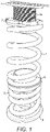
- FIG. 1 there is shown an example of applicant's own earlier prior art arrangement.
- a pair of springs 2, 3 are arrange in series between a pair of spring seats 4, 5, the upper spring seat 4 of which is adjustable.
- the upper spring seat 4 is formed by an upper flange 6 having a shaft 4b extending therefrom into the windings of the abutting end 2a of the spring 2 so as to retain it in position.
- the upper flange in use, engages against a part of the vehicle suspension to transmit the force from the suspension strut and spring to the vehicle.
- the outer surface 4a of the shaft 4b of the upper spring seat 4 is threaded and has a flange member 7 against which the upper end 2a of the spring 2 engages.
- the flange member 7 is threadably mounted on the outer surface 4a of the shaft so as to be longitudinally moveable along the shaft 4b by winding along the thread. In this way, the compression of the spring can be adjusted.
- the spring seat is formed a main body 14 having a shaft 14b which, in use, extends into the windings of the abutting end of the spring so as to retain the spring in position on the shaft.
- the shaft 14b of the main body 14 has a radial flange 14c formed on one end thereof and outer surface 14a of the shaft 14b, extending away from the radial flange, has a male thread 15a provided thereon on which is carried a first adjustable member in the form of an adjustable flange member 17.
- the adjustable flange member 17 is annular shaped and has a female thread 18 provided on its inner cylindrical surface 17a which is complementary to the thread 15a formed on the outer surface 14a of the shaft
- the flange member 17 is thereby threadably mounted on the outer surface 14a of the shaft 14b so as to be longitudinally moveable along the shaft 14b between a fully retracted position in which it engages against the radial flange 14c of the main body 14 and a fully extended position in which it is wound to the bottom of the thread 15a as shown in Figure 2 .
- the main body 14 furthermore has a female thread 15b formed on its inner cylindrical surface extending from the end on which the radial flange 14c is carried.
- a second adjustable member 19 shown in figures 5a and 5b , comprises a flange 19b with a shaft 19a extending therefrom having a male thread 19c formed on its outer cylindrical surface which is complementary to the female thread 15b formed on the inner cylindrical surface of the main body 14 such that the shaft 19a of the second adjustable member 19 is screwingly engageable into the main body 14 in order to secure it thereto, the separation between the flange 19b of the second adjustable member 19 and the radial flange 14c of the main body 14 being adjustable by screwing the second adjustable member 19 into and out of the main body 14.
- the main body 14 includes circumferentially extending slots 20 in the outer circumferential face of the radial flange 14c, as shown in Figures 2 and 6 , the slots 20 being distributed around the circumference of the flange 14c.
- An adjusting tool 21 includes teeth 22 thereon which are engageable in the slots 20 in order to enable a torsional load to be applied through the tool 21 to the main body 14.
- the adjustable spring seat is assembled with the first adjustable member 17 wound fully onto the thread 15a on the outer surface 14a of the main body 14 so as to abut against on side of the radial flange 14c of the main body, and the second adjustable member 19 wound fully into the female thread 15b formed on the inner surface of the main body 14.
- the face of the flange 19b of the second adjustable member 19 is engaged against a suspension mounting point in a manner known in the art and an end of a suspension spring is engaged over the protruding end of the threaded shaft 14b of the main body 14.
- the male thread 15a is of opposite hand to the female thread 15b, and the length of the male thread is substantially equal to the length of the female thread so that the adjustment range of each is the same.
- the teeth 22 of the adjustment tool 21 are engaged in slots 20 in the radial flange 14c and the main body 14 is rotated, the load on the first and second adjustable members from the suspension engagement point and the spring preventing rotation so that the two adjustment members 17, 19 are extended away from each other, compressing the spring.
- the body 14 may be rotated in the opposite direction in order to retract the adjustable members towards each other and thereby reduce the load on the spring.
- the tool 21 may be used to restrain the main body 14 from rotation whilst one or both of the adjustable members 17, 19 are rotated in order to adjust the load on the spring.
Landscapes
- Engineering & Computer Science (AREA)
- Mechanical Engineering (AREA)
- General Engineering & Computer Science (AREA)
- Fluid-Damping Devices (AREA)
- Finger-Pressure Massage (AREA)
- Mechanical Operated Clutches (AREA)
Claims (13)
- Siège à ressort réglable pour amortisseur comprenant un corps cylindrique (14) ayant un premier filetage (15a) formé sur sa surface externe (14a) et un deuxième filetage (15b) formé sur sa surface interne, un premier élément réglable constitué d'une première bride (17) ayant une surface interne filetée (18) qui peut s'engager avec le premier filetage (15a) du corps (14) de sorte que la première bride (17) peut être vissée le long du premier filetage (15a) afin de régler la position longitudinale de la première bride (17) sur le corps (14), et un deuxième élément réglable (19) constitué d'une deuxième bride (19b) fournie sur une extrémité d'un arbre (19a), l'arbre (19a) ayant un filetage (19c) formé sur sa surface externe complémentaire du deuxième filetage (15b) du corps (14) de sorte que l'arbre (19a) du deuxième élément réglable (19) peut s'engager avec le deuxième filetage (15b) à travers une extrémité du corps (14) et peut être vissé le long du deuxième filetage (15b) afin de régler l'espace longitudinal entre la deuxième bride (19b) et ladite extrémité du corps cylindrique (14), moyennant quoi la séparation entre les première et deuxième brides (17, 19b) peut être réglée par le déplacement de l'une ou l'autre ou des deux parmi lesdites première et deuxième brides (17, 19b), caractérisé en ce que lesdites première et deuxième brides (17, 19b) sont mobiles indépendamment l'une de l'autre.
- Siège à ressort réglable selon la revendication 1, dans lequel le corps (14) comprend des moyens d'engagement (20) au moyen desquels une force de torsion peut être appliquée au corps (14) soit pour le faire tourner afin d'effectuer un réglage simultané à la fois des premier et deuxième éléments réglables (17, 19b), soit de sorte à le maintenir contre une rotation durant le réglage des premier et/ou deuxième éléments réglables (17, 19b).
- Siège à ressort réglable selon la revendication 2, dans lequel le corps (14) comprend des ouvertures radiales (20) dans sa surface externe (14a) dans lesquelles peuvent s'engager des dents (22) fournies sur un outil de retenue (21) afin d'appliquer un couple au corps (14).
- Siège à ressort réglable selon la revendication 3, dans lequel les ouvertures radiales (20) sont réparties au moins partiellement autour de la circonférence du corps (14).
- Siège à ressort réglable selon la revendication 3 ou la revendication 4, dans lequel un ensemble d'ouvertures radiales (20) sont fournies sur plus d'une position le long de la longueur du corps (14) afin de permettre à l'outil (21) de s'engager avec un ensemble d'ouvertures (20) même si un ensemble est masqué par le premier élément réglable (17).
- Siège à ressort réglable selon la revendication 3 ou la revendication 4, dans lequel les ouvertures radiales (20) sont formées dans une troisième bride (14c) qui est fournie sur la surface externe (14a) du corps (14) et est solidaire en rotation avec celle-ci.
- Siège à ressort réglable selon la revendication 6, dans lequel la troisième bride (14c) est formée d'un seul tenant avec le corps (14) .
- Siège à ressort réglable selon l'une quelconque des revendications 3 à 6, dans lequel les ouvertures (20) sont formées comme des fentes s'étendant circonférentiellement.
- Siège à ressort réglable selon l'une quelconque des revendications précédentes, dans lequel les premier et deuxième filetages (15a, 15b) sont en sens opposés de sorte que les première et deuxième brides (17, 19b) peuvent être simultanément écartées l'une de l'autre par la rotation du corps (14) dans une direction, et rapprochées l'une de l'autre par la rotation corps (14) dans l'autre direction.
- Siège à ressort réglable selon l'une quelconque des revendications précédentes, comprenant en outre un moyen d'arrêt associé avec chaque élément réglable (17, 19b) pour lui permettre d'être bloqué en position contre un mouvement longitudinal involontaire.
- Siège à ressort réglable selon l'une quelconque des revendications précédentes, dans lequel la dimension externe du corps (14) est dimensionnée, en utilisation, pour être un ajustement serré à l'intérieur d'un ressort avec lequel le siège à ressort s'engage pour minimiser un mouvement latéral du ressort sur le siège.
- Ensemble de réglage d'amortisseur comprenant au moins un ressort agencé afin de, en utilisation, s'étendre entre une paire de sièges à ressort espacés, dans lequel au moins un parmi les sièges à ressort est réglable et est formé selon l'une quelconque des revendications précédentes.
- Ensemble de réglage d'amortisseur selon la revendication 12, dans lequel ledit siège à ressort réglable s'engage avec une extrémité du ressort qui, en utilisation, est située le plus haut dans l'ensemble d'amortisseur.
Applications Claiming Priority (2)
| Application Number | Priority Date | Filing Date | Title |
|---|---|---|---|
| GB1909944.9A GB2585682A (en) | 2019-07-11 | 2019-07-11 | Suspension adjustment assembly |
| PCT/GB2020/051628 WO2021005356A1 (fr) | 2019-07-11 | 2020-07-07 | Ensemble de réglage de suspension |
Publications (2)
| Publication Number | Publication Date |
|---|---|
| EP3959088A1 EP3959088A1 (fr) | 2022-03-02 |
| EP3959088B1 true EP3959088B1 (fr) | 2022-11-02 |
Family
ID=67700283
Family Applications (1)
| Application Number | Title | Priority Date | Filing Date |
|---|---|---|---|
| EP20742817.8A Active EP3959088B1 (fr) | 2019-07-11 | 2020-07-07 | Support de ressort ajustable |
Country Status (7)
| Country | Link |
|---|---|
| US (1) | US11912094B2 (fr) |
| EP (1) | EP3959088B1 (fr) |
| ES (1) | ES2937077T3 (fr) |
| GB (1) | GB2585682A (fr) |
| PL (1) | PL3959088T3 (fr) |
| PT (1) | PT3959088T (fr) |
| WO (1) | WO2021005356A1 (fr) |
Cited By (1)
| Publication number | Priority date | Publication date | Assignee | Title |
|---|---|---|---|---|
| DE102023118270A1 (de) | 2023-07-11 | 2025-01-16 | Thyssenkrupp Ag | Höhenniveaueinstellungssystem für ein Fahrwerk eines Kraftfahrzeugs |
Families Citing this family (2)
| Publication number | Priority date | Publication date | Assignee | Title |
|---|---|---|---|---|
| US12077028B2 (en) * | 2020-03-03 | 2024-09-03 | Shock Therapy Suspension, Inc. | Coilover shock with adjustable crossover |
| US12459326B2 (en) * | 2023-04-27 | 2025-11-04 | Shock Therapy Suspension, Inc. | Adjustable shock adapter |
Family Cites Families (15)
| Publication number | Priority date | Publication date | Assignee | Title |
|---|---|---|---|---|
| JPH1137203A (ja) * | 1997-07-22 | 1999-02-12 | Hiroyuki Shibazaki | スプリング高調整装置 |
| US20020038929A1 (en) * | 2000-06-23 | 2002-04-04 | Now Leo Martin | Shock absorber |
| US6827184B1 (en) * | 2003-07-18 | 2004-12-07 | Wei-Li Lin | Shock-absorbing device of an automobile |
| US7891645B2 (en) * | 2006-10-27 | 2011-02-22 | Hayes Bicycle Group, Inc. | Adjustable and progressive coil spring system for two wheeled vehicles |
| US9140325B2 (en) * | 2009-03-19 | 2015-09-22 | Fox Factory, Inc. | Methods and apparatus for selective spring pre-load adjustment |
| DE102009016252A1 (de) | 2009-04-03 | 2010-10-07 | Schaeffler Technologies Gmbh & Co. Kg | Höhenverstelleinrichtung für Radaufhängungen von Kraftfahrzeugen |
| US9744826B2 (en) * | 2013-05-31 | 2017-08-29 | Fox Factory, Inc. | Methods and apparatus for adjusting a spring pre-load |
| FR3009539B1 (fr) * | 2013-08-06 | 2015-09-04 | Decathlon Sa | Dispositif de suspension telescopique muni d'un systeme de reperage de precontrainte |
| US9869360B2 (en) | 2014-04-23 | 2018-01-16 | Justin Smith | Multi-piece nut for use with a shock |
| GB2529254A (en) | 2014-08-15 | 2016-02-17 | William Blankson | Adjustable kit for helical compression springs to fit front axle of cars from Audi, SEAT, VW, SKODA, Lamborghini, BMW, Porsche, Mercedes, Ferarri |
| US9844993B2 (en) * | 2014-10-31 | 2017-12-19 | TAP Worldwide, LLC | Two-piece adjustable strut spacer |
| KR102062876B1 (ko) * | 2018-04-13 | 2020-01-06 | 이상욱 | 차량 현가장치용 코일스프링 지지대 |
| GB2575079B (en) * | 2018-06-28 | 2021-01-13 | R5 Mss Ltd | Suspension adjustment assembly |
| US10953717B2 (en) * | 2019-05-13 | 2021-03-23 | Honda Motor Co., Ltd. | Wear mitigated damper assembly for a vehicle |
| US12128723B2 (en) * | 2020-03-27 | 2024-10-29 | Fox Factory, Inc. | Wear sleeve for a shock body |
-
2019
- 2019-07-11 GB GB1909944.9A patent/GB2585682A/en not_active Withdrawn
-
2020
- 2020-07-07 ES ES20742817T patent/ES2937077T3/es active Active
- 2020-07-07 PT PT207428178T patent/PT3959088T/pt unknown
- 2020-07-07 WO PCT/GB2020/051628 patent/WO2021005356A1/fr not_active Ceased
- 2020-07-07 PL PL20742817.8T patent/PL3959088T3/pl unknown
- 2020-07-07 US US17/296,801 patent/US11912094B2/en active Active
- 2020-07-07 EP EP20742817.8A patent/EP3959088B1/fr active Active
Cited By (1)
| Publication number | Priority date | Publication date | Assignee | Title |
|---|---|---|---|---|
| DE102023118270A1 (de) | 2023-07-11 | 2025-01-16 | Thyssenkrupp Ag | Höhenniveaueinstellungssystem für ein Fahrwerk eines Kraftfahrzeugs |
Also Published As
| Publication number | Publication date |
|---|---|
| WO2021005356A1 (fr) | 2021-01-14 |
| US11912094B2 (en) | 2024-02-27 |
| GB2585682A (en) | 2021-01-20 |
| EP3959088A1 (fr) | 2022-03-02 |
| GB201909944D0 (en) | 2019-08-28 |
| PT3959088T (pt) | 2023-01-27 |
| US20220001714A1 (en) | 2022-01-06 |
| ES2937077T3 (es) | 2023-03-23 |
| PL3959088T3 (pl) | 2023-10-02 |
Similar Documents
| Publication | Publication Date | Title |
|---|---|---|
| EP3959088B1 (fr) | Support de ressort ajustable | |
| EP3587151B1 (fr) | Ensemble d'ajustement de suspension | |
| CN113840990B (zh) | 具有偏置活塞的液压压缩止动件 | |
| US8573573B2 (en) | Spring strut arrangement for wheel suspension of motor vehicles | |
| US7784800B2 (en) | Height adjustment on a wheel suspension for motor vehicles | |
| EP3338002B1 (fr) | Ressort élastomère pour véhicule | |
| US20090107781A1 (en) | Vibration Damper Having a Rebound Buffer | |
| EP3830444B1 (fr) | Amortisseur hydraulique à amortissement variable pour suspension de véhicule | |
| EP1591690B1 (fr) | Amortisseur hydraulique pour vehicule automobile | |
| WO2014164104A1 (fr) | Butée anti-rebonds à double taux | |
| JP7295109B2 (ja) | ばねの垂直位置調整用の電気機械式調整装置を備えた車両懸架装置用ダンパ及びばねユニット | |
| WO2022171382A1 (fr) | Ensemble de réglage de suspension | |
| CN103998815B (zh) | 液压阻尼器及其组装方法 | |
| US20140375041A1 (en) | Vehicle body reinforcement unit | |
| US12151526B2 (en) | Spring seat, method for producing a spring seat, vibration damper and level adjustment device | |
| US20130106038A1 (en) | Spring Seat to Provide Adjustable Spring Height for Vehicle Suspension System | |
| KR20200142207A (ko) | 전동식 차고 조절 장치 | |
| JP6431392B2 (ja) | 油圧緩衝器 | |
| EP4450846A1 (fr) | Amortisseur avec soupape de conduite de base | |
| EP3517802B1 (fr) | Limiteurs de suspension réglables pour agencements de suspension | |
| EP3594028B1 (fr) | Ensemble de verrouillage rotatif pour augmenter et réduire la hauteur d'un véhicule | |
| US12240284B2 (en) | High stroke efficiency hydraulic bump stop | |
| RU2140364C1 (ru) | Стойка активной подвески переднеприводного автомобиля | |
| GB2585431A (en) | Length and adjustment device | |
| GB2297065A (en) | Suspension strut |
Legal Events
| Date | Code | Title | Description |
|---|---|---|---|
| STAA | Information on the status of an ep patent application or granted ep patent |
Free format text: STATUS: UNKNOWN |
|
| STAA | Information on the status of an ep patent application or granted ep patent |
Free format text: STATUS: THE INTERNATIONAL PUBLICATION HAS BEEN MADE |
|
| PUAI | Public reference made under article 153(3) epc to a published international application that has entered the european phase |
Free format text: ORIGINAL CODE: 0009012 |
|
| STAA | Information on the status of an ep patent application or granted ep patent |
Free format text: STATUS: REQUEST FOR EXAMINATION WAS MADE |
|
| 17P | Request for examination filed |
Effective date: 20211126 |
|
| AK | Designated contracting states |
Kind code of ref document: A1 Designated state(s): AL AT BE BG CH CY CZ DE DK EE ES FI FR GB GR HR HU IE IS IT LI LT LU LV MC MK MT NL NO PL PT RO RS SE SI SK SM TR |
|
| GRAP | Despatch of communication of intention to grant a patent |
Free format text: ORIGINAL CODE: EPIDOSNIGR1 |
|
| STAA | Information on the status of an ep patent application or granted ep patent |
Free format text: STATUS: GRANT OF PATENT IS INTENDED |
|
| DAV | Request for validation of the european patent (deleted) | ||
| DAX | Request for extension of the european patent (deleted) | ||
| INTG | Intention to grant announced |
Effective date: 20220524 |
|
| RAP3 | Party data changed (applicant data changed or rights of an application transferred) |
Owner name: R5 MSS LIMITED |
|
| GRAS | Grant fee paid |
Free format text: ORIGINAL CODE: EPIDOSNIGR3 |
|
| GRAA | (expected) grant |
Free format text: ORIGINAL CODE: 0009210 |
|
| STAA | Information on the status of an ep patent application or granted ep patent |
Free format text: STATUS: THE PATENT HAS BEEN GRANTED |
|
| AK | Designated contracting states |
Kind code of ref document: B1 Designated state(s): AL AT BE BG CH CY CZ DE DK EE ES FI FR GB GR HR HU IE IS IT LI LT LU LV MC MK MT NL NO PL PT RO RS SE SI SK SM TR |
|
| REG | Reference to a national code |
Ref country code: GB Ref legal event code: FG4D |
|
| REG | Reference to a national code |
Ref country code: CH Ref legal event code: EP Ref country code: AT Ref legal event code: REF Ref document number: 1528515 Country of ref document: AT Kind code of ref document: T Effective date: 20221115 |
|
| REG | Reference to a national code |
Ref country code: DE Ref legal event code: R096 Ref document number: 602020006078 Country of ref document: DE |
|
| REG | Reference to a national code |
Ref country code: IE Ref legal event code: FG4D |
|
| REG | Reference to a national code |
Ref country code: PT Ref legal event code: SC4A Ref document number: 3959088 Country of ref document: PT Date of ref document: 20230127 Kind code of ref document: T Free format text: AVAILABILITY OF NATIONAL TRANSLATION Effective date: 20230123 |
|
| REG | Reference to a national code |
Ref country code: NL Ref legal event code: FP |
|
| REG | Reference to a national code |
Ref country code: LT Ref legal event code: MG9D |
|
| REG | Reference to a national code |
Ref country code: ES Ref legal event code: FG2A Ref document number: 2937077 Country of ref document: ES Kind code of ref document: T3 Effective date: 20230323 |
|
| REG | Reference to a national code |
Ref country code: AT Ref legal event code: MK05 Ref document number: 1528515 Country of ref document: AT Kind code of ref document: T Effective date: 20221102 |
|
| PG25 | Lapsed in a contracting state [announced via postgrant information from national office to epo] |
Ref country code: SE Free format text: LAPSE BECAUSE OF FAILURE TO SUBMIT A TRANSLATION OF THE DESCRIPTION OR TO PAY THE FEE WITHIN THE PRESCRIBED TIME-LIMIT Effective date: 20221102 Ref country code: NO Free format text: LAPSE BECAUSE OF FAILURE TO SUBMIT A TRANSLATION OF THE DESCRIPTION OR TO PAY THE FEE WITHIN THE PRESCRIBED TIME-LIMIT Effective date: 20230202 Ref country code: LT Free format text: LAPSE BECAUSE OF FAILURE TO SUBMIT A TRANSLATION OF THE DESCRIPTION OR TO PAY THE FEE WITHIN THE PRESCRIBED TIME-LIMIT Effective date: 20221102 Ref country code: FI Free format text: LAPSE BECAUSE OF FAILURE TO SUBMIT A TRANSLATION OF THE DESCRIPTION OR TO PAY THE FEE WITHIN THE PRESCRIBED TIME-LIMIT Effective date: 20221102 Ref country code: AT Free format text: LAPSE BECAUSE OF FAILURE TO SUBMIT A TRANSLATION OF THE DESCRIPTION OR TO PAY THE FEE WITHIN THE PRESCRIBED TIME-LIMIT Effective date: 20221102 |
|
| PG25 | Lapsed in a contracting state [announced via postgrant information from national office to epo] |
Ref country code: RS Free format text: LAPSE BECAUSE OF FAILURE TO SUBMIT A TRANSLATION OF THE DESCRIPTION OR TO PAY THE FEE WITHIN THE PRESCRIBED TIME-LIMIT Effective date: 20221102 Ref country code: LV Free format text: LAPSE BECAUSE OF FAILURE TO SUBMIT A TRANSLATION OF THE DESCRIPTION OR TO PAY THE FEE WITHIN THE PRESCRIBED TIME-LIMIT Effective date: 20221102 Ref country code: IS Free format text: LAPSE BECAUSE OF FAILURE TO SUBMIT A TRANSLATION OF THE DESCRIPTION OR TO PAY THE FEE WITHIN THE PRESCRIBED TIME-LIMIT Effective date: 20230302 Ref country code: HR Free format text: LAPSE BECAUSE OF FAILURE TO SUBMIT A TRANSLATION OF THE DESCRIPTION OR TO PAY THE FEE WITHIN THE PRESCRIBED TIME-LIMIT Effective date: 20221102 Ref country code: GR Free format text: LAPSE BECAUSE OF FAILURE TO SUBMIT A TRANSLATION OF THE DESCRIPTION OR TO PAY THE FEE WITHIN THE PRESCRIBED TIME-LIMIT Effective date: 20230203 |
|
| PG25 | Lapsed in a contracting state [announced via postgrant information from national office to epo] |
Ref country code: SM Free format text: LAPSE BECAUSE OF FAILURE TO SUBMIT A TRANSLATION OF THE DESCRIPTION OR TO PAY THE FEE WITHIN THE PRESCRIBED TIME-LIMIT Effective date: 20221102 Ref country code: RO Free format text: LAPSE BECAUSE OF FAILURE TO SUBMIT A TRANSLATION OF THE DESCRIPTION OR TO PAY THE FEE WITHIN THE PRESCRIBED TIME-LIMIT Effective date: 20221102 Ref country code: EE Free format text: LAPSE BECAUSE OF FAILURE TO SUBMIT A TRANSLATION OF THE DESCRIPTION OR TO PAY THE FEE WITHIN THE PRESCRIBED TIME-LIMIT Effective date: 20221102 Ref country code: DK Free format text: LAPSE BECAUSE OF FAILURE TO SUBMIT A TRANSLATION OF THE DESCRIPTION OR TO PAY THE FEE WITHIN THE PRESCRIBED TIME-LIMIT Effective date: 20221102 Ref country code: CZ Free format text: LAPSE BECAUSE OF FAILURE TO SUBMIT A TRANSLATION OF THE DESCRIPTION OR TO PAY THE FEE WITHIN THE PRESCRIBED TIME-LIMIT Effective date: 20221102 |
|
| PGFP | Annual fee paid to national office [announced via postgrant information from national office to epo] |
Ref country code: PT Payment date: 20230606 Year of fee payment: 4 Ref country code: NL Payment date: 20230614 Year of fee payment: 4 Ref country code: FR Payment date: 20230620 Year of fee payment: 4 |
|
| REG | Reference to a national code |
Ref country code: DE Ref legal event code: R097 Ref document number: 602020006078 Country of ref document: DE |
|
| PG25 | Lapsed in a contracting state [announced via postgrant information from national office to epo] |
Ref country code: SK Free format text: LAPSE BECAUSE OF FAILURE TO SUBMIT A TRANSLATION OF THE DESCRIPTION OR TO PAY THE FEE WITHIN THE PRESCRIBED TIME-LIMIT Effective date: 20221102 Ref country code: AL Free format text: LAPSE BECAUSE OF FAILURE TO SUBMIT A TRANSLATION OF THE DESCRIPTION OR TO PAY THE FEE WITHIN THE PRESCRIBED TIME-LIMIT Effective date: 20221102 |
|
| PLBE | No opposition filed within time limit |
Free format text: ORIGINAL CODE: 0009261 |
|
| STAA | Information on the status of an ep patent application or granted ep patent |
Free format text: STATUS: NO OPPOSITION FILED WITHIN TIME LIMIT |
|
| PGFP | Annual fee paid to national office [announced via postgrant information from national office to epo] |
Ref country code: BE Payment date: 20230616 Year of fee payment: 4 |
|
| 26N | No opposition filed |
Effective date: 20230803 |
|
| PGFP | Annual fee paid to national office [announced via postgrant information from national office to epo] |
Ref country code: IT Payment date: 20230731 Year of fee payment: 4 Ref country code: ES Payment date: 20230810 Year of fee payment: 4 |
|
| PG25 | Lapsed in a contracting state [announced via postgrant information from national office to epo] |
Ref country code: SI Free format text: LAPSE BECAUSE OF FAILURE TO SUBMIT A TRANSLATION OF THE DESCRIPTION OR TO PAY THE FEE WITHIN THE PRESCRIBED TIME-LIMIT Effective date: 20221102 |
|
| PGFP | Annual fee paid to national office [announced via postgrant information from national office to epo] |
Ref country code: PL Payment date: 20230529 Year of fee payment: 4 Ref country code: DE Payment date: 20230531 Year of fee payment: 4 |
|
| PG25 | Lapsed in a contracting state [announced via postgrant information from national office to epo] |
Ref country code: MC Free format text: LAPSE BECAUSE OF FAILURE TO SUBMIT A TRANSLATION OF THE DESCRIPTION OR TO PAY THE FEE WITHIN THE PRESCRIBED TIME-LIMIT Effective date: 20221102 |
|
| PG25 | Lapsed in a contracting state [announced via postgrant information from national office to epo] |
Ref country code: MC Free format text: LAPSE BECAUSE OF FAILURE TO SUBMIT A TRANSLATION OF THE DESCRIPTION OR TO PAY THE FEE WITHIN THE PRESCRIBED TIME-LIMIT Effective date: 20221102 |
|
| REG | Reference to a national code |
Ref country code: CH Ref legal event code: PL |
|
| PG25 | Lapsed in a contracting state [announced via postgrant information from national office to epo] |
Ref country code: LU Free format text: LAPSE BECAUSE OF NON-PAYMENT OF DUE FEES Effective date: 20230707 |
|
| PG25 | Lapsed in a contracting state [announced via postgrant information from national office to epo] |
Ref country code: LU Free format text: LAPSE BECAUSE OF NON-PAYMENT OF DUE FEES Effective date: 20230707 |
|
| REG | Reference to a national code |
Ref country code: IE Ref legal event code: MM4A |
|
| PG25 | Lapsed in a contracting state [announced via postgrant information from national office to epo] |
Ref country code: CH Free format text: LAPSE BECAUSE OF NON-PAYMENT OF DUE FEES Effective date: 20230731 |
|
| PG25 | Lapsed in a contracting state [announced via postgrant information from national office to epo] |
Ref country code: IE Free format text: LAPSE BECAUSE OF NON-PAYMENT OF DUE FEES Effective date: 20230707 |
|
| PG25 | Lapsed in a contracting state [announced via postgrant information from national office to epo] |
Ref country code: IE Free format text: LAPSE BECAUSE OF NON-PAYMENT OF DUE FEES Effective date: 20230707 |
|
| PG25 | Lapsed in a contracting state [announced via postgrant information from national office to epo] |
Ref country code: BG Free format text: LAPSE BECAUSE OF FAILURE TO SUBMIT A TRANSLATION OF THE DESCRIPTION OR TO PAY THE FEE WITHIN THE PRESCRIBED TIME-LIMIT Effective date: 20221102 |
|
| PG25 | Lapsed in a contracting state [announced via postgrant information from national office to epo] |
Ref country code: BG Free format text: LAPSE BECAUSE OF FAILURE TO SUBMIT A TRANSLATION OF THE DESCRIPTION OR TO PAY THE FEE WITHIN THE PRESCRIBED TIME-LIMIT Effective date: 20221102 |
|
| REG | Reference to a national code |
Ref country code: DE Ref legal event code: R119 Ref document number: 602020006078 Country of ref document: DE |
|
| REG | Reference to a national code |
Ref country code: NL Ref legal event code: MM Effective date: 20240801 |
|
| GBPC | Gb: european patent ceased through non-payment of renewal fee |
Effective date: 20240707 |
|
| PG25 | Lapsed in a contracting state [announced via postgrant information from national office to epo] |
Ref country code: DE Free format text: LAPSE BECAUSE OF NON-PAYMENT OF DUE FEES Effective date: 20250201 Ref country code: PT Free format text: LAPSE BECAUSE OF NON-PAYMENT OF DUE FEES Effective date: 20250107 |
|
| PG25 | Lapsed in a contracting state [announced via postgrant information from national office to epo] |
Ref country code: NL Free format text: LAPSE BECAUSE OF NON-PAYMENT OF DUE FEES Effective date: 20240801 |
|
| PG25 | Lapsed in a contracting state [announced via postgrant information from national office to epo] |
Ref country code: BE Free format text: LAPSE BECAUSE OF NON-PAYMENT OF DUE FEES Effective date: 20240731 |
|
| PG25 | Lapsed in a contracting state [announced via postgrant information from national office to epo] |
Ref country code: FR Free format text: LAPSE BECAUSE OF NON-PAYMENT OF DUE FEES Effective date: 20240731 |
|
| PG25 | Lapsed in a contracting state [announced via postgrant information from national office to epo] |
Ref country code: GB Free format text: LAPSE BECAUSE OF NON-PAYMENT OF DUE FEES Effective date: 20240707 |
|
| REG | Reference to a national code |
Ref country code: BE Ref legal event code: MM Effective date: 20240731 |
|
| PG25 | Lapsed in a contracting state [announced via postgrant information from national office to epo] |
Ref country code: IT Free format text: LAPSE BECAUSE OF NON-PAYMENT OF DUE FEES Effective date: 20240707 |
|
| PG25 | Lapsed in a contracting state [announced via postgrant information from national office to epo] |
Ref country code: CY Free format text: LAPSE BECAUSE OF FAILURE TO SUBMIT A TRANSLATION OF THE DESCRIPTION OR TO PAY THE FEE WITHIN THE PRESCRIBED TIME-LIMIT; INVALID AB INITIO Effective date: 20200707 |
|
| PG25 | Lapsed in a contracting state [announced via postgrant information from national office to epo] |
Ref country code: HU Free format text: LAPSE BECAUSE OF FAILURE TO SUBMIT A TRANSLATION OF THE DESCRIPTION OR TO PAY THE FEE WITHIN THE PRESCRIBED TIME-LIMIT; INVALID AB INITIO Effective date: 20200707 |
|
| REG | Reference to a national code |
Ref country code: ES Ref legal event code: FD2A Effective date: 20250826 |
|
| PG25 | Lapsed in a contracting state [announced via postgrant information from national office to epo] |
Ref country code: ES Free format text: LAPSE BECAUSE OF NON-PAYMENT OF DUE FEES Effective date: 20240708 |
|
| PG25 | Lapsed in a contracting state [announced via postgrant information from national office to epo] |
Ref country code: TR Free format text: LAPSE BECAUSE OF FAILURE TO SUBMIT A TRANSLATION OF THE DESCRIPTION OR TO PAY THE FEE WITHIN THE PRESCRIBED TIME-LIMIT Effective date: 20221102 |
|
| PG25 | Lapsed in a contracting state [announced via postgrant information from national office to epo] |
Ref country code: PL Free format text: LAPSE BECAUSE OF NON-PAYMENT OF DUE FEES Effective date: 20240707 |