EP3596242B1 - Procédé de traitement par fusion d'alliage d'aluminium et matériau précurseur d'alliage d'aluminium - Google Patents
Procédé de traitement par fusion d'alliage d'aluminium et matériau précurseur d'alliage d'aluminium Download PDFInfo
- Publication number
- EP3596242B1 EP3596242B1 EP18712414.4A EP18712414A EP3596242B1 EP 3596242 B1 EP3596242 B1 EP 3596242B1 EP 18712414 A EP18712414 A EP 18712414A EP 3596242 B1 EP3596242 B1 EP 3596242B1
- Authority
- EP
- European Patent Office
- Prior art keywords
- energy beam
- aluminum alloy
- trailing
- precursor material
- leading
- Prior art date
- Legal status (The legal status is an assumption and is not a legal conclusion. Google has not performed a legal analysis and makes no representation as to the accuracy of the status listed.)
- Active
Links
Images






Classifications
-
- B—PERFORMING OPERATIONS; TRANSPORTING
- B23—MACHINE TOOLS; METAL-WORKING NOT OTHERWISE PROVIDED FOR
- B23K—SOLDERING OR UNSOLDERING; WELDING; CLADDING OR PLATING BY SOLDERING OR WELDING; CUTTING BY APPLYING HEAT LOCALLY, e.g. FLAME CUTTING; WORKING BY LASER BEAM
- B23K15/00—Electron-beam welding or cutting
- B23K15/0046—Welding
- B23K15/0086—Welding welding for purposes other than joining, e.g. build-up welding
-
- B—PERFORMING OPERATIONS; TRANSPORTING
- B22—CASTING; POWDER METALLURGY
- B22F—WORKING METALLIC POWDER; MANUFACTURE OF ARTICLES FROM METALLIC POWDER; MAKING METALLIC POWDER; APPARATUS OR DEVICES SPECIALLY ADAPTED FOR METALLIC POWDER
- B22F10/00—Additive manufacturing of workpieces or articles from metallic powder
- B22F10/20—Direct sintering or melting
- B22F10/25—Direct deposition of metal particles, e.g. direct metal deposition [DMD] or laser engineered net shaping [LENS]
-
- B—PERFORMING OPERATIONS; TRANSPORTING
- B22—CASTING; POWDER METALLURGY
- B22F—WORKING METALLIC POWDER; MANUFACTURE OF ARTICLES FROM METALLIC POWDER; MAKING METALLIC POWDER; APPARATUS OR DEVICES SPECIALLY ADAPTED FOR METALLIC POWDER
- B22F10/00—Additive manufacturing of workpieces or articles from metallic powder
- B22F10/30—Process control
- B22F10/36—Process control of energy beam parameters
- B22F10/364—Process control of energy beam parameters for post-heating, e.g. remelting
-
- B—PERFORMING OPERATIONS; TRANSPORTING
- B22—CASTING; POWDER METALLURGY
- B22F—WORKING METALLIC POWDER; MANUFACTURE OF ARTICLES FROM METALLIC POWDER; MAKING METALLIC POWDER; APPARATUS OR DEVICES SPECIALLY ADAPTED FOR METALLIC POWDER
- B22F10/00—Additive manufacturing of workpieces or articles from metallic powder
- B22F10/30—Process control
- B22F10/38—Process control to achieve specific product aspects, e.g. surface smoothness, density, porosity or hollow structures
-
- B—PERFORMING OPERATIONS; TRANSPORTING
- B22—CASTING; POWDER METALLURGY
- B22F—WORKING METALLIC POWDER; MANUFACTURE OF ARTICLES FROM METALLIC POWDER; MAKING METALLIC POWDER; APPARATUS OR DEVICES SPECIALLY ADAPTED FOR METALLIC POWDER
- B22F12/00—Apparatus or devices specially adapted for additive manufacturing; Auxiliary means for additive manufacturing; Combinations of additive manufacturing apparatus or devices with other processing apparatus or devices
- B22F12/40—Radiation means
- B22F12/44—Radiation means characterised by the configuration of the radiation means
- B22F12/45—Two or more
-
- B—PERFORMING OPERATIONS; TRANSPORTING
- B23—MACHINE TOOLS; METAL-WORKING NOT OTHERWISE PROVIDED FOR
- B23K—SOLDERING OR UNSOLDERING; WELDING; CLADDING OR PLATING BY SOLDERING OR WELDING; CUTTING BY APPLYING HEAT LOCALLY, e.g. FLAME CUTTING; WORKING BY LASER BEAM
- B23K15/00—Electron-beam welding or cutting
- B23K15/004—Tandem beams or torches, i.e. working simultaneously with several beams or torches
-
- B—PERFORMING OPERATIONS; TRANSPORTING
- B23—MACHINE TOOLS; METAL-WORKING NOT OTHERWISE PROVIDED FOR
- B23K—SOLDERING OR UNSOLDERING; WELDING; CLADDING OR PLATING BY SOLDERING OR WELDING; CUTTING BY APPLYING HEAT LOCALLY, e.g. FLAME CUTTING; WORKING BY LASER BEAM
- B23K15/00—Electron-beam welding or cutting
- B23K15/06—Electron-beam welding or cutting within a vacuum chamber
-
- B—PERFORMING OPERATIONS; TRANSPORTING
- B23—MACHINE TOOLS; METAL-WORKING NOT OTHERWISE PROVIDED FOR
- B23K—SOLDERING OR UNSOLDERING; WELDING; CLADDING OR PLATING BY SOLDERING OR WELDING; CUTTING BY APPLYING HEAT LOCALLY, e.g. FLAME CUTTING; WORKING BY LASER BEAM
- B23K26/00—Working by laser beam, e.g. welding, cutting or boring
- B23K26/02—Positioning or observing the workpiece, e.g. with respect to the point of impact; Aligning, aiming or focusing the laser beam
- B23K26/06—Shaping the laser beam, e.g. by masks or multi-focusing
- B23K26/0604—Shaping the laser beam, e.g. by masks or multi-focusing by a combination of beams
- B23K26/0608—Shaping the laser beam, e.g. by masks or multi-focusing by a combination of beams in the same heat affected zone [HAZ]
-
- B—PERFORMING OPERATIONS; TRANSPORTING
- B23—MACHINE TOOLS; METAL-WORKING NOT OTHERWISE PROVIDED FOR
- B23K—SOLDERING OR UNSOLDERING; WELDING; CLADDING OR PLATING BY SOLDERING OR WELDING; CUTTING BY APPLYING HEAT LOCALLY, e.g. FLAME CUTTING; WORKING BY LASER BEAM
- B23K26/00—Working by laser beam, e.g. welding, cutting or boring
- B23K26/02—Positioning or observing the workpiece, e.g. with respect to the point of impact; Aligning, aiming or focusing the laser beam
- B23K26/06—Shaping the laser beam, e.g. by masks or multi-focusing
- B23K26/067—Dividing the beam into multiple beams, e.g. multi-focusing
-
- B—PERFORMING OPERATIONS; TRANSPORTING
- B23—MACHINE TOOLS; METAL-WORKING NOT OTHERWISE PROVIDED FOR
- B23K—SOLDERING OR UNSOLDERING; WELDING; CLADDING OR PLATING BY SOLDERING OR WELDING; CUTTING BY APPLYING HEAT LOCALLY, e.g. FLAME CUTTING; WORKING BY LASER BEAM
- B23K26/00—Working by laser beam, e.g. welding, cutting or boring
- B23K26/02—Positioning or observing the workpiece, e.g. with respect to the point of impact; Aligning, aiming or focusing the laser beam
- B23K26/06—Shaping the laser beam, e.g. by masks or multi-focusing
- B23K26/067—Dividing the beam into multiple beams, e.g. multi-focusing
- B23K26/0676—Dividing the beam into multiple beams, e.g. multi-focusing into dependently operating sub-beams, e.g. an array of spots with fixed spatial relationship or for performing simultaneously identical operations
-
- B—PERFORMING OPERATIONS; TRANSPORTING
- B23—MACHINE TOOLS; METAL-WORKING NOT OTHERWISE PROVIDED FOR
- B23K—SOLDERING OR UNSOLDERING; WELDING; CLADDING OR PLATING BY SOLDERING OR WELDING; CUTTING BY APPLYING HEAT LOCALLY, e.g. FLAME CUTTING; WORKING BY LASER BEAM
- B23K26/00—Working by laser beam, e.g. welding, cutting or boring
- B23K26/02—Positioning or observing the workpiece, e.g. with respect to the point of impact; Aligning, aiming or focusing the laser beam
- B23K26/06—Shaping the laser beam, e.g. by masks or multi-focusing
- B23K26/073—Shaping the laser spot
-
- B—PERFORMING OPERATIONS; TRANSPORTING
- B23—MACHINE TOOLS; METAL-WORKING NOT OTHERWISE PROVIDED FOR
- B23K—SOLDERING OR UNSOLDERING; WELDING; CLADDING OR PLATING BY SOLDERING OR WELDING; CUTTING BY APPLYING HEAT LOCALLY, e.g. FLAME CUTTING; WORKING BY LASER BEAM
- B23K26/00—Working by laser beam, e.g. welding, cutting or boring
- B23K26/02—Positioning or observing the workpiece, e.g. with respect to the point of impact; Aligning, aiming or focusing the laser beam
- B23K26/06—Shaping the laser beam, e.g. by masks or multi-focusing
- B23K26/073—Shaping the laser spot
- B23K26/0734—Shaping the laser spot into an annular shape
-
- B—PERFORMING OPERATIONS; TRANSPORTING
- B23—MACHINE TOOLS; METAL-WORKING NOT OTHERWISE PROVIDED FOR
- B23K—SOLDERING OR UNSOLDERING; WELDING; CLADDING OR PLATING BY SOLDERING OR WELDING; CUTTING BY APPLYING HEAT LOCALLY, e.g. FLAME CUTTING; WORKING BY LASER BEAM
- B23K26/00—Working by laser beam, e.g. welding, cutting or boring
- B23K26/02—Positioning or observing the workpiece, e.g. with respect to the point of impact; Aligning, aiming or focusing the laser beam
- B23K26/06—Shaping the laser beam, e.g. by masks or multi-focusing
- B23K26/073—Shaping the laser spot
- B23K26/0736—Shaping the laser spot into an oval shape, e.g. elliptic shape
-
- B—PERFORMING OPERATIONS; TRANSPORTING
- B23—MACHINE TOOLS; METAL-WORKING NOT OTHERWISE PROVIDED FOR
- B23K—SOLDERING OR UNSOLDERING; WELDING; CLADDING OR PLATING BY SOLDERING OR WELDING; CUTTING BY APPLYING HEAT LOCALLY, e.g. FLAME CUTTING; WORKING BY LASER BEAM
- B23K26/00—Working by laser beam, e.g. welding, cutting or boring
- B23K26/08—Devices involving relative movement between laser beam and workpiece
-
- B—PERFORMING OPERATIONS; TRANSPORTING
- B23—MACHINE TOOLS; METAL-WORKING NOT OTHERWISE PROVIDED FOR
- B23K—SOLDERING OR UNSOLDERING; WELDING; CLADDING OR PLATING BY SOLDERING OR WELDING; CUTTING BY APPLYING HEAT LOCALLY, e.g. FLAME CUTTING; WORKING BY LASER BEAM
- B23K26/00—Working by laser beam, e.g. welding, cutting or boring
- B23K26/12—Working by laser beam, e.g. welding, cutting or boring in a special environment or atmosphere, e.g. in an enclosure
- B23K26/1224—Working by laser beam, e.g. welding, cutting or boring in a special environment or atmosphere, e.g. in an enclosure in vacuum
-
- B—PERFORMING OPERATIONS; TRANSPORTING
- B23—MACHINE TOOLS; METAL-WORKING NOT OTHERWISE PROVIDED FOR
- B23K—SOLDERING OR UNSOLDERING; WELDING; CLADDING OR PLATING BY SOLDERING OR WELDING; CUTTING BY APPLYING HEAT LOCALLY, e.g. FLAME CUTTING; WORKING BY LASER BEAM
- B23K26/00—Working by laser beam, e.g. welding, cutting or boring
- B23K26/20—Bonding
- B23K26/32—Bonding taking account of the properties of the material involved
- B23K26/323—Bonding taking account of the properties of the material involved involving parts made of dissimilar metallic material
-
- B—PERFORMING OPERATIONS; TRANSPORTING
- B23—MACHINE TOOLS; METAL-WORKING NOT OTHERWISE PROVIDED FOR
- B23K—SOLDERING OR UNSOLDERING; WELDING; CLADDING OR PLATING BY SOLDERING OR WELDING; CUTTING BY APPLYING HEAT LOCALLY, e.g. FLAME CUTTING; WORKING BY LASER BEAM
- B23K26/00—Working by laser beam, e.g. welding, cutting or boring
- B23K26/34—Laser welding for purposes other than joining
- B23K26/342—Build-up welding
-
- B—PERFORMING OPERATIONS; TRANSPORTING
- B23—MACHINE TOOLS; METAL-WORKING NOT OTHERWISE PROVIDED FOR
- B23K—SOLDERING OR UNSOLDERING; WELDING; CLADDING OR PLATING BY SOLDERING OR WELDING; CUTTING BY APPLYING HEAT LOCALLY, e.g. FLAME CUTTING; WORKING BY LASER BEAM
- B23K26/00—Working by laser beam, e.g. welding, cutting or boring
- B23K26/70—Auxiliary operations or equipment
- B23K26/702—Auxiliary equipment
- B23K26/703—Cooling arrangements
-
- B—PERFORMING OPERATIONS; TRANSPORTING
- B33—ADDITIVE MANUFACTURING TECHNOLOGY
- B33Y—ADDITIVE MANUFACTURING, i.e. MANUFACTURING OF THREE-DIMENSIONAL [3D] OBJECTS BY ADDITIVE DEPOSITION, ADDITIVE AGGLOMERATION OR ADDITIVE LAYERING, e.g. BY 3D PRINTING, STEREOLITHOGRAPHY OR SELECTIVE LASER SINTERING
- B33Y10/00—Processes of additive manufacturing
-
- B—PERFORMING OPERATIONS; TRANSPORTING
- B33—ADDITIVE MANUFACTURING TECHNOLOGY
- B33Y—ADDITIVE MANUFACTURING, i.e. MANUFACTURING OF THREE-DIMENSIONAL [3D] OBJECTS BY ADDITIVE DEPOSITION, ADDITIVE AGGLOMERATION OR ADDITIVE LAYERING, e.g. BY 3D PRINTING, STEREOLITHOGRAPHY OR SELECTIVE LASER SINTERING
- B33Y50/00—Data acquisition or data processing for additive manufacturing
- B33Y50/02—Data acquisition or data processing for additive manufacturing for controlling or regulating additive manufacturing processes
-
- B—PERFORMING OPERATIONS; TRANSPORTING
- B33—ADDITIVE MANUFACTURING TECHNOLOGY
- B33Y—ADDITIVE MANUFACTURING, i.e. MANUFACTURING OF THREE-DIMENSIONAL [3D] OBJECTS BY ADDITIVE DEPOSITION, ADDITIVE AGGLOMERATION OR ADDITIVE LAYERING, e.g. BY 3D PRINTING, STEREOLITHOGRAPHY OR SELECTIVE LASER SINTERING
- B33Y70/00—Materials specially adapted for additive manufacturing
-
- B—PERFORMING OPERATIONS; TRANSPORTING
- B33—ADDITIVE MANUFACTURING TECHNOLOGY
- B33Y—ADDITIVE MANUFACTURING, i.e. MANUFACTURING OF THREE-DIMENSIONAL [3D] OBJECTS BY ADDITIVE DEPOSITION, ADDITIVE AGGLOMERATION OR ADDITIVE LAYERING, e.g. BY 3D PRINTING, STEREOLITHOGRAPHY OR SELECTIVE LASER SINTERING
- B33Y70/00—Materials specially adapted for additive manufacturing
- B33Y70/10—Composites of different types of material, e.g. mixtures of ceramics and polymers or mixtures of metals and biomaterials
-
- C—CHEMISTRY; METALLURGY
- C22—METALLURGY; FERROUS OR NON-FERROUS ALLOYS; TREATMENT OF ALLOYS OR NON-FERROUS METALS
- C22C—ALLOYS
- C22C21/00—Alloys based on aluminium
- C22C21/06—Alloys based on aluminium with magnesium as the next major constituent
- C22C21/08—Alloys based on aluminium with magnesium as the next major constituent with silicon
-
- B—PERFORMING OPERATIONS; TRANSPORTING
- B22—CASTING; POWDER METALLURGY
- B22F—WORKING METALLIC POWDER; MANUFACTURE OF ARTICLES FROM METALLIC POWDER; MAKING METALLIC POWDER; APPARATUS OR DEVICES SPECIALLY ADAPTED FOR METALLIC POWDER
- B22F10/00—Additive manufacturing of workpieces or articles from metallic powder
- B22F10/20—Direct sintering or melting
- B22F10/28—Powder bed fusion, e.g. selective laser melting [SLM] or electron beam melting [EBM]
-
- B—PERFORMING OPERATIONS; TRANSPORTING
- B22—CASTING; POWDER METALLURGY
- B22F—WORKING METALLIC POWDER; MANUFACTURE OF ARTICLES FROM METALLIC POWDER; MAKING METALLIC POWDER; APPARATUS OR DEVICES SPECIALLY ADAPTED FOR METALLIC POWDER
- B22F10/00—Additive manufacturing of workpieces or articles from metallic powder
- B22F10/30—Process control
- B22F10/32—Process control of the atmosphere, e.g. composition or pressure in a building chamber
-
- B—PERFORMING OPERATIONS; TRANSPORTING
- B22—CASTING; POWDER METALLURGY
- B22F—WORKING METALLIC POWDER; MANUFACTURE OF ARTICLES FROM METALLIC POWDER; MAKING METALLIC POWDER; APPARATUS OR DEVICES SPECIALLY ADAPTED FOR METALLIC POWDER
- B22F3/00—Manufacture of workpieces or articles from metallic powder characterised by the manner of compacting or sintering; Apparatus specially adapted therefor ; Presses and furnaces
- B22F3/24—After-treatment of workpieces or articles
- B22F2003/248—Thermal after-treatment
-
- B—PERFORMING OPERATIONS; TRANSPORTING
- B23—MACHINE TOOLS; METAL-WORKING NOT OTHERWISE PROVIDED FOR
- B23K—SOLDERING OR UNSOLDERING; WELDING; CLADDING OR PLATING BY SOLDERING OR WELDING; CUTTING BY APPLYING HEAT LOCALLY, e.g. FLAME CUTTING; WORKING BY LASER BEAM
- B23K2103/00—Materials to be soldered, welded or cut
- B23K2103/08—Non-ferrous metals or alloys
- B23K2103/10—Aluminium or alloys thereof
-
- B—PERFORMING OPERATIONS; TRANSPORTING
- B23—MACHINE TOOLS; METAL-WORKING NOT OTHERWISE PROVIDED FOR
- B23K—SOLDERING OR UNSOLDERING; WELDING; CLADDING OR PLATING BY SOLDERING OR WELDING; CUTTING BY APPLYING HEAT LOCALLY, e.g. FLAME CUTTING; WORKING BY LASER BEAM
- B23K26/00—Working by laser beam, e.g. welding, cutting or boring
- B23K26/34—Laser welding for purposes other than joining
-
- B—PERFORMING OPERATIONS; TRANSPORTING
- B23—MACHINE TOOLS; METAL-WORKING NOT OTHERWISE PROVIDED FOR
- B23K—SOLDERING OR UNSOLDERING; WELDING; CLADDING OR PLATING BY SOLDERING OR WELDING; CUTTING BY APPLYING HEAT LOCALLY, e.g. FLAME CUTTING; WORKING BY LASER BEAM
- B23K9/00—Arc welding or cutting
- B23K9/04—Welding for other purposes than joining, e.g. built-up welding
-
- Y—GENERAL TAGGING OF NEW TECHNOLOGICAL DEVELOPMENTS; GENERAL TAGGING OF CROSS-SECTIONAL TECHNOLOGIES SPANNING OVER SEVERAL SECTIONS OF THE IPC; TECHNICAL SUBJECTS COVERED BY FORMER USPC CROSS-REFERENCE ART COLLECTIONS [XRACs] AND DIGESTS
- Y02—TECHNOLOGIES OR APPLICATIONS FOR MITIGATION OR ADAPTATION AGAINST CLIMATE CHANGE
- Y02P—CLIMATE CHANGE MITIGATION TECHNOLOGIES IN THE PRODUCTION OR PROCESSING OF GOODS
- Y02P10/00—Technologies related to metal processing
- Y02P10/25—Process efficiency
Definitions
- the present invention relates generally to a composition and method for fusion processing, and more particularly to an aluminum alloy composition and method for fusion processing aluminum alloys, such as for additive manufacturing aluminum alloys susceptible to hot cracking.
- Aluminum alloys such as aluminum 6061 alloy, are widely used in modern aerospace and defense structures due to their light weight, relatively high strength, and corrosion resistance. Although strong, aluminum alloys also are easily worked because they are typically malleable and ductile, which allows for traditional fabrication techniques to be utilized, including casting, welding, and machining.
- US 2016/175929 A1 discloses a method of fabricating parts out of metallic, intermetallic, ceramic, ceramic matrix composite, or metal matrix composite material with discontinuous reinforcement, includes melting or sintering powder particles by means of a high-energy beam.
- the powder used is a single powder of particles that present sphericity lying in the range 0.8 to 1.0 and of form factor lying in the range 1 to ⁇ 2, each powder particle presenting substantially identical mean composition, and the grain size distribution of the particles of the powder is narrowed around the mean diameter value d50% in such a manner that: (d90%-d50%)/d50% ⁇ /0.66; and (d50%-d10%)/d50% ⁇ /0.33; with a "span": (d90%-d10%)/d50% ⁇ /1.00.
- WO03/031108 A1 discloses a welding process which avoids cracking in welding, in repair welding or in cladding of parts of metallic alloys which are sensitive to hot cracking.
- the process is using a first heat source, directed to the parts of the metallic alloy forming a melt pool on the parts of metal or metallic alloy.
- the heat source and the parts are moved relative to each other.
- the process is characterized in that there is one or more additional heat sources directed to the parts of metal or metallic alloy and following the first heat source in a distance and with substantially the same speed and in the same direction as the first heat source.
- the additional heat source or heat sources are directed to the solidification region of the melt pool generated by the first heat source.
- the power of the additional heat source is set such as to reduce the local cooling rate of the solidification region of the melt pool, or to even shortly reheat this region without substantial remelting or with no remelting it at all and thereby reducing the tensile stresses or even inducing compressive stresses.
- a central equiaxed zone might also be enhanced.
- US 2010/270274 A1 discloses a method for controlling an electron beam process wherein a wire is melted and deposited on a substrate as a molten pool comprises generating the electron beam with a complex raster pattern, and directing the beam onto an outer surface of the wire to thereby control a location of the wire with respect to the molten pool. Directing the beam selectively heats the outer surface of the wire and maintains the position of the wire with respect to the molten pool.
- An apparatus for controlling an electron beam process includes a beam gun adapted for generating the electron beam, and a controller adapted for providing the electron beam with a complex raster pattern and for directing the electron beam onto an outer surface of the wire to control a location of the wire with respect to the molten pool.
- US 2008/251504 A1 discloses a laser-welding apparatus including a laser source, an incoming laser beam produced by the laser source, and a beam splitter that splits the incoming laser beam to form a leading beam and a trailing beam.
- a first focusing lens may focus the leading beam and a second focusing lens may focus the trailing beam to form a trailing-beam pattern on a workpiece.
- the trailing-beam pattern may include a crescent-shape having arms and a tail portion
- US 2005/173380 A1 discloses an e lectron gun mounted on top of a vacuum chamber, the gun emitting an electron beam vertically downward towards a substrate placed upon a three axis movable stage, creating a molten pool on the substrate, which is translated along an automatically generated, pre-programmed path in a plane normal to the beam by an automated numerical controller.
- a wire feeder and spool surround the beam in an annular ring, providing continuous material feed and constant orientation of the wire to the beam and pool, producing a high rate of material deposition and near net shape geometry.
- Integrated machining and inspection heads sequentially machine each layer to net shape then non-destructively inspect each layer.
- a heat and microstructure management system employs chilled oil or liquid metal coolant circulating through a vat surrounding the movable stage, supported by an actuator that gradually submerges the substrate as the deposited layers grow, the circulating coolant removing heat and machine chips.
- An integrated system architecture including six subsystems ensures density (no voids), accuracy, reliability, repeatability and verifiability: an energy management system manages energy input, including beam density, diameter and position; a geometry acquisition and path planning system acquires the cross-sectional two dimensional geometry from a three dimensional computer generated mathematical model and computes numerical control paths for deposit, machining and inspection processes; a material deposition system controls the placement and rate of material deposited; an integrated machining system subtracts excess material from each layer; an inspection and repair system detects, removes, refills and remachines defective areas; a heat management system eliminates excess heat by controlling the temperature and flow of a liquid metal coolant, and improves the microstructure of the deposited material via transducer generated sonic frequencies; a supervisory control
- EP0 785 043 A1 discloses a weld metal used in electron beam welding of aluminium alloys which is an aluminium-magnesium-silicon alloy of type 6061, whose Mg/Si ratio is at least the stoichiometric ratio, preferably at least 1.75 by weight. Also claimed are electron beam welding using the weld metal and a component so welded.
- Alclad 6061 comprises Mg in the range 0.8 to 1.2 percent.
- the present disclosure provides a unique aluminum alloy composition and method of fusion processing that reduces hot cracking, improves compositional control, reduces porosity, and/or enhances the strength and/or ductility of the fusion processed alloy, among other considerations.
- the present disclosure provides an aluminum alloy precursor material, and fusion process using the same, which may be utilized for forming article(s) that meet the prescribed compositional specifications of aluminum 6061 alloy (Al 6061) after such fusion processing.
- the unique aluminum alloy precursor material and/or fusion process in accordance with the present disclosure may provide such Al 6061 articles(s) that are substantially defect free, and which meet or exceed the desired strength and/or ductility requirements for particular application(s).
- the present inventors have found that high-energy fusion processing of alloys, such as additive manufacturing or welding of aluminum 6061 alloy, results in vaporization or boiling off of high vapor pressure constituents when the alloy is being processed. This phenomenon may be exacerbated by those processes conducted in a vacuum, but is not limited thereto. It has been found that the vaporization of these high vapor pressure constituents may render the fusion processed alloy with an altered composition compared to the original material, which may result in the fusion processed alloy having a composition and/or exhibiting one or more properties that fall outside of prescribed or desired limits.
- the present inventors have found that high energy fusion processing of aluminum 6061 alloy results in a substantial amount of magnesium being lost due to vaporization during such processing.
- magnesium is an alloying agent that contributes to strength of the alloy, particularly during subsequent heat treatment.
- the loss of magnesium in the fusion processed alloy may result in decreased strength, decreased heat treat response, and/or have other undesirable characteristics.
- a unique aluminum alloy composition that enriches the magnesium content in the precursor material for a fusion process, such that the material after fusion processing exhibits the prescribed compositional specifications of conventional aluminum 6061 alloy after the fusion processing.
- the aluminum alloy precursor composition is based on the Al 6061 alloy, but enriches the magnesium content in an amount from 2.5 to 5.0 weight percent of the precursor alloy, such that the resulting fusion processed alloy has a composition in accordance with Aluminum Association International Alloy Designations and Chemical Composition Limits for Wrought Aluminum and Wrought Aluminum Alloys -- 2015 ((incorporated herein by reference) for wrought Al 6061 alloy.
- the present inventors also have found that vaporization of high vapor pressure constituents in the alloy during high energy fusion processing may introduce undesirable anomalies in the material after fusion processing, such as porosity.
- the present inventors have found that high energy fusion processing of aluminum 6061 alloy results in zinc being lost due to vaporization during such processing.
- zinc may be considered a tramp element (e.g., not added for performance), but may be present in the alloy because it is expensive to completely remove in the refining process, and is often introduced in recycled aluminum.
- the loss of zinc during high energy fusion processing has been found to contribute to porosity in the solidified fusion processed alloy, which may thus reduce strength and/or ductility, among other undesirable characteristics.
- a unique aluminum alloy composition is provided that minimizes the zinc content to 0.005 weight % in the precursor material for a fusion process, such that the material after fusion processing exhibits less porosity and is preferably defect free.
- the aluminum alloy precursor composition is based on the Al 6061 alloy, but further restricts the zinc content to no more than 0.005 weight percent of the alloy, with the precursor alloy preferably being free of zinc.
- fusion processing techniques that are conducted under vacuum conditions may exacerbate the problem of vaporization of high vapor pressure alloy constituents when the alloy is being processed.
- some traditional fusion processes may be conducted under vacuum conditions with pressure levels greatly below atmospheric pressure (e.g., less than 100 microtorr), and at elevated processing temperatures sufficient to melt the alloy, which may result in vaporization of some alloy constituents, such as magnesium and zinc, when such processes are utilized.
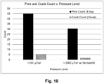
- a method of fusion processing in which the process is conducted in a vacuum chamber, and the pressure level of the vacuum chamber is 100 microtorr or greater for reducing vaporization of one or more alloying agents at the processing temperature.
- alloys such as Al 6061 alloy are prone to hot cracking during fusion processing where the alloy is liquefied during the process and forms a molten pool which thereafter solidifies. It is believed that during such processes, a volumetric change occurs during the liquid-to-solid phase change of the alloy during solidification, such that shrinkage occurs in the cooler region of the melt pool near the solid interface. Strain in the melt pool caused by such shrinkage may cause porosity or openings to develop in this cooler solidifying region, and if the available supply of liquid metal is insufficient or incapable of filling these openings between the solidifying metal, then hot cracking may occur.
- dendritic structures in the melt pool may form narrow channels between solidifying grains that act to choke off or prevent the liquid metal from replenishing the reduced volume caused by solidification shrinkage.
- dendritic structures may form narrow channels between solidifying grains that act to choke off or prevent the liquid metal from replenishing the reduced volume caused by solidification shrinkage.
- undesirable large dendritic microstructures may be particularly prone to forming during solidification.
- These dendrites also have low strength at the elevated processing temperatures, which may result in hot tears and porosity that collectively reduce mechanical properties.
- a unique aluminum alloy precursor composition includes one or more grain refiners that act as seed materials which promote precipitation of grains in the solidifying region of the melt pool, thereby disrupting growth of large dendritic structures.
- the aluminum alloy precursor composition is based on the Al 6061 alloy, but specifies titanium to be present in the alloy in an amount from 0.05 to 0.15 weight percent of the alloy, or more preferably from 0.10 to 0.15 weight percent, for restricting dendritic grain growth and reducing hot tearing of the aluminum alloy.
- the aluminum alloy precursor composition may further include one additional grain refiner in addition to titanium.
- the at least one additional grain refiner may be boron.
- the one additional grain refiner may include boron, which may be present in the aluminum alloy precursor material in an amount from 0.001 to 0.05 weight percent, or more preferably from 0.001 to 0.002 weight percent.
- the available boron in the precursor composition is combined with at least a portion of the titanium in the form of titanium diboride, which may further enhance the grain refining effect.
- the present inventors also have found that exposing the solidifying region of the melt pool to an energy beam during fusion processing may act to disrupt dendritic grain growth and/or redistribute liquid constituents in the melt pool to prevent hot cracking.
- a method of fusion processing includes: providing a raw material in solid state form; exposing the raw material to a leading energy beam thereby liquefying the raw material; forming a melt pool with the liquefied raw material, where the melt pool has a leading region and a trailing region; and exposing the trailing region of the melt pool to a trailing energy beam.
- the raw material used for the exemplary fusion processing method may be any of the foregoing unique aluminum alloy composition(s), alone or in combination, which may be provided in wire or powder form, for example.
- the trailing energy beam may be directed toward a liquid-solid region of the melt pool to prevent hot cracking as the melt pool solidifies.
- the trailing energy beam may be configured to have a power level, power density, pulsation, beam pattern, and/or positional relationship that is sufficient to break-up or disrupt the formation of dendritic structures in the trailing region of the melt pool.
- the trailing energy beam may be configured to re-heat or re-melt dendritic structures in the melt pool, enhance agitation through convective currents and/or pulsing electromagnetic fields that may cause turbulence in the melt pool, and/or redistribute liquid constituents in the melt pool to replenish lost volume due to solidification shrinkage, among other considerations.
- the trailing energy beam may be configured in a beam pattern that corresponds to a shape of the trailing region of the melt pool.
- the trailing energy beam may be configured in a concave pattern that opens toward the leading region of the melt pool.
- the trailing energy beam may be spaced apart from the leading energy beam at a fixed distance as the respective energy beams move together in a travel direction, such as along an x-y plane relative to a substrate.
- the trailing energy beam may be dynamically altered during the process so as to further enhance agitation of the melt pool and provide a stirring effect from convective currents and/or electromagnetic forces.
- the trailing energy beam may move back and forth at the trailing region, or may cycle through various positions relative to the leading energy beam.
- Such process(es) may enhance redistribution of liquid melt from the leading region toward the solidifying portions of the trailing region, which may prevent hot cracking, reduce porosity, and improve strength and ductility of the manufactured part.
- any of the foregoing unique alloy composition(s) and/or foregoing fusion process(es) may be utilized for welding or additively manufacturing.
- exemplary welding processes may include: laser beam welding, electron beam welding, arc welding (such as gas metal arc welding, gas tungsten arc welding, plasma arc welding, shielded metal arc welding, etc.), or other forms of welding in which the supply material is liquefied to form a melt pool that is thereafter solidified.
- arc welding such as gas metal arc welding, gas tungsten arc welding, plasma arc welding, shielded metal arc welding, etc.
- Exemplary additive manufacturing processes may include powder bed techniques, such as Selective Laser Sintering (SLS), Selective Laser Melting (SLM), and Electron Beam Melting (EBM); and direct energy deposition techniques, such as Laser Engineering Net Shape (LENS), powder or wire-based Laser Metal Deposition (LMD), and Electron Beam Additive Manufacturing (EBAM); or other forms of additive manufacturing in which the supply material is liquefied to form a melt pool that is thereafter solidified.
- powder bed techniques such as Selective Laser Sintering (SLS), Selective Laser Melting (SLM), and Electron Beam Melting (EBM)
- direct energy deposition techniques such as Laser Engineering Net Shape (LENS), powder or wire-based Laser Metal Deposition (LMD), and Electron Beam Additive Manufacturing (EBAM); or other forms of additive manufacturing in which the supply material is liquefied to form a melt pool that is thereafter solidified.
- the invention provides an aluminum alloy precursor material for fusion processing, the aluminum alloy precursor material having a chemical composition, in weight % of the aluminum alloy precursor material, comprising: Si from 0.40 to 0.80%; Cu from 0.15 to 0.40%; Mg from 2.5 to 5.0%; Cr from 0.04 to 0.35%; Ti from 0.05 to 0.15%; optionally B from 0.001 to 0.05%; Fe from 0.0 to 0.7%; Mn from 0.0 to 0.15%; Zn from 0.0 to 0.005%; one or more other impurities from 0.0 to 0.05% for each of the one or more other impurities, the total amount of the one or more other impurities may be from 0.0 to 0.10%; and Al from 50% or greater and constituting the balance.
- the present invention provides a method of forming an aluminum alloy article by fusion processing comprising: obtaining an aluminum alloy precursor material in solid state form, the aluminum alloy precursor material having a chemical composition, in weight % of the aluminum alloy precursor material, including: Si from 0.40 to 0.80%; Cu from 0.15 to 0.40%; Mg from 2.5% to 5.0%; Cr from 0.04 to 0.35%; Ti from 0.0 to 0.15%; optionally B from 0.001 to 0.05%; Fe from 0.0 to 0.7%; Mn from 0.0 to 0.15%; Zn from 0.0 to 0.005%; one or more other impurities from 0.0 to 0.05% for each of the one or more other impurities, wherein the total amount of the one or more other impurities is from 0.0 to 0.10%; and Al from 50% or greater and constituting the balance; exposing the aluminum alloy precursor material to at least one direct energy source sufficient to heat and liquefy the precursor material; forming a melt pool with the liquefied precursor material on a substrate, wherein the
- the present disclosure provides a method of fusion processing comprising: obtaining an aluminum alloy precursor material in solid state form, the aluminum alloy precursor material having a chemical composition, in weight % of the aluminum alloy precursor material, including: Si from 0.40 to 0.80%; Cu from 0.15 to 0.40%; Mg from 0.8 to 5.0%; Cr from 0.04 to 0.35%; Ti from 0.0 to 0.15%; Fe from 0.0 to 0.7%; Mn from 0.0 to 0.15%; Zn from 0.0 to 0.25%; and Al from 50% or greater and constituting the balance; exposing the aluminum alloy precursor material to a leading energy beam, thereby liquefying the precursor material; forming a melt pool with the liquefied precursor material, wherein the melt pool has a leading region and a trailing region; and exposing the trailing region of the melt pool to a trailing energy beam.
- Hot cracking is a high-temperature cracking mechanism that is mainly a function of how a metal alloy solidifies from a liquid melt, and thus is a problem for those processes in which a melt pool is formed.
- hot cracking occurs during solidification of the melt pool where dendritic structures act to block liquid melt from replenishing regions of the melt pool where volume is lost due to solidification shrinkage.
- Aluminum alloys, such as aluminum 6061 alloy may be particularly susceptible to hot cracking, and traditionally have been considered difficult to process via welding and/or additive manufacturing.
- an aluminum alloy precursor material (also referred to as a supply material or raw material) is provided for subsequent fusion processing to produce an aluminum alloy article.
- aluminum alloy refers to a metal alloy having aluminum as a base element (e.g., greater than 50% by weight of the alloy composition), and including one or more other alloying elements.
- Fusion processing refers to a process in which the supplied raw material is at least partially liquefied (or melted) to form a melt pool that is thereafter solidified. Fusion processing includes, but is not limited to, welding processes and additive manufacturing processes.
- article may refer to any item or object formed by the solidified material, including, but not limited to, welds, welded components, solidified layers, and other three-dimensional structures.
- the exemplary aluminum alloy precursor material may have a chemical composition that is based on the chemical composition of the Al 6061 alloy, but with modifications to the precursor composition to accommodate for subsequent fusion processing.
- the aluminum alloy precursor material includes aluminum as a base element (e.g., greater than 50 wt.%), and also may include alloying elements of silicon, magnesium, copper, and chromium.
- the exemplary aluminum alloy precursor material also may include titanium and one or more additional grain refiners, as discussed in further detail below.
- One or more impurities also may be present in the aluminum alloy precursor material.
- Major impurities may include iron, manganese, and zinc. Minor impurities may include various other elements, as discussed further below.
- Silicon (Si) may be included in the precursor aluminum alloy composition for reducing melting temperature and enhancing fluidity. Silicon also may be used to combine with magnesium to produce Mg 2 Si, which enhances heat-treatability via precipitation hardening. According to the invention, the silicon is present in the aluminum alloy precursor material in an amount from about 0.4 to about 0.8 weight percent of the aluminum alloy precursor composition. For example, in one or more embodiments, the silicon is present in an amount of about 0.4, 0.45, 0.5, 0.55, 0.6, 0.65, 0.7, 0.75, or 0.8 weight percent of the aluminum alloy precursor composition, including all values and subranges between the stated values.
- Copper (Cu) may be included in the precursor aluminum alloy composition for combining with other alloying elements, such as magnesium, to increase strength, particularly after heat treatment.
- the copper is present in the aluminum alloy precursor material in an amount from about 0.15 to about 0.40 weight percent of the aluminum alloy precursor composition.
- the copper is present in an amount of about 0.15, 0.20, 0.25, 0.30, 0.35, or 0.40 weight percent of the aluminum alloy precursor composition, including all values and subranges between the stated values.
- Chromium (Cr) may be included in the precursor aluminum alloy composition for controlling grain structure and preventing recrystallization during heat treatment.
- the chromium also may reduce stress corrosion susceptibility and improve toughness.
- the chromium is present in the aluminum alloy precursor material in an amount from about 0.04 to about 0.35 weight percent of the aluminum alloy precursor composition.
- the chromium is present in an amount of about 0.04, 0.10, 0.15, 0.20, 0.25, 0.30, or 0.35 weight percent of the aluminum alloy precursor composition, including all values and subranges between the stated values.
- Magnesium (Mg) may be included in the precursor aluminum alloy composition for combining with other alloying elements, such as silicon, in order to enhance strength, such as via heat treatment and precipitation hardening, among other factors.
- the magnesium may increase strength without substantially decreasing ductility.
- the present inventors have found that high-energy fusion processing of aluminum alloys may result in vaporization or boiling off of magnesium when the alloy is being processed. This may be caused by the relatively high vapor pressure of magnesium at the processing temperature during fusion processing. For example, and not limitation, the vapor pressure of magnesium at 652 degrees Celsius is about 3.4 torr.
- the problem with vaporization of magnesium may be exacerbated when the fusion process is conducted in a vacuum, but is not limited to vacuum processes.
- the loss of magnesium during fusion processing may render the final fusion processed alloy with a composition that is outside of prescribed compositional limits.
- the reduced magnesium content in the fusion processed alloy may decrease the strength, heat treat response, or have other undesirable characteristics.
- the aluminum alloy precursor material has an increased amount of magnesium compared to the aluminum 6061 alloy, such that the precursor material after fusion processing exhibits the prescribed compositional specifications of conventional aluminum 6061 alloy after the fusion processing.
- the magnesium is present in the aluminum alloy precursor material according to the invention in an amount from about 2.5 to about 5.0 weight percent of the aluminum alloy precursor composition. More preferably, in some embodiments, the magnesium is present in the aluminum alloy precursor material in an amount up to about 3.0 weight percent. In one or more embodiments, the magnesium is present in an amount of about 2.5, 3.0, 3.5, 4.0 or 5.0 weight percent of the aluminum alloy precursor composition, including all values and subranges between the stated values.
- Iron (Fe), manganese (Mn), and/or zinc (Zn) may be present in the aluminum alloy precursor material and may represent impurities or tramp elements that are not specifically added to the alloy for performance.
- the aluminum alloy precursor material may include iron in an amount from about 0.0 up to about 0.7 weight percent of the aluminum alloy precursor composition.
- the aluminum alloy precursor material is free of iron.
- the iron may be present in an amount of about 0.10, 0.20, 0.30, 0.4, 0.5, or 0.35 weight percent of the aluminum alloy precursor composition, including all values and subranges between the stated values.
- the aluminum alloy precursor material may include manganese in an amount from about 0.0 up to about 0.15 weight percent of the aluminum alloy precursor composition.
- the aluminum alloy precursor material is free of manganese.
- the manganese may be present in an amount of about 0.05, 0.10, or 0.15 weight percent of the aluminum alloy precursor composition, including all values and subranges between the stated values.
- the present inventors have found that high-energy fusion processing of aluminum alloys may result in vaporization or boiling off of zinc when the alloy is being processed. This may be caused by the relatively high vapor pressure of zinc at the processing temperature during fusion processing. For example, and not limitation, the vapor pressure of zinc at 652 degrees Celsius is about 30 torr. The problem with vaporization of zinc may be exacerbated when the fusion process is conducted in a vacuum, but is not limited to vacuum processes. Because zinc may be considered a tramp element in Al 6061 alloy, its loss during fusion processing may not be a concern for the composition of the final fusion processed alloy. However, the present inventors also have found that vaporization of zinc in the precursor alloy during high energy fusion processing may introduce undesirable anomalies in the final fusion processed alloy, such as porosity, which may reduce strength and/or ductility.
- the aluminum alloy precursor material minimizes the zinc content compared to conventional compositional specifications for the aluminum 6061 alloy, such that the material after fusion processing exhibits less porosity and is preferably defect free.
- the aluminum alloy precursor material may include zinc in an amount from about 0.0 up to about 0.005 weight percent of the aluminum alloy precursor composition.
- the aluminum alloy precursor material is free of zinc.
- the zinc may be present in an amount of about 0.001, 0.002, 0.003, 0.004, or 0.005 weight percent of the aluminum alloy precursor composition, including all values and subranges between the stated values.
- the present inventors have found that aluminum alloys, such as Al 6061, are prone to hot cracking during fusion processing where the alloy is liquefied during the process and forms a molten pool which thereafter solidifies. It is believed that during such fusion processing, a volumetric change occurs during the liquid-to-solid phase change of the alloy during solidification, such that shrinkage occurs in the cooler region of the melt pool near the solid interface. Strain in the melt pool caused by such shrinkage may cause porosity or openings to develop in this cooler solidifying region, and if the available supply of liquid metal is insufficient or incapable of filling these openings between the solidifying metal, then hot cracking may occur.
- the issue of hot cracking may be exacerbated by the formation of dendritic structures in the melt pool, which may form narrow channels between solidifying grains that act to choke off or prevent the liquid metal from replenishing the reduced volume caused by solidification shrinkage.
- dendritic structures in the melt pool, which may form narrow channels between solidifying grains that act to choke off or prevent the liquid metal from replenishing the reduced volume caused by solidification shrinkage.
- undesirable large dendritic microstructures may be particularly prone to forming during solidification.
- These dendrites typically have low strength at the elevated processing temperatures, which may result in hot tears and porosity that collectively reduce mechanical properties.
- the exemplary aluminum alloy precursor material may include one or more grain refiners that act as seed materials which promote precipitation of grains in the solidifying region of the melt pool, thereby disrupting growth of large dendritic structures.
- the aluminum alloy precursor material includes titanium as a grain refiner for restricting dendritic grain growth and reducing hot tearing of the aluminum alloy during fusion processing.
- the titanium is present in the aluminum alloy precursor material in an amount from about 0.05 to about 0.15 weight percent of the aluminum alloy composition. More preferably, in some embodiments, the titanium is present in the aluminum alloy precursor material in an amount from about 0.10 to about 0.15 weight percent of the aluminum alloy precursor composition. In one or more embodiments, the titanium is present in an amount of about 0.05, 0.07, 0.09, 0.11, 0.13, or 0.15 weight percent of the aluminum alloy precursor composition, including all values and subranges between the stated values.
- the aluminum alloy precursor material also may include boron.
- boron may be present in the aluminum alloy precursor material in an amount from about 0.001 to 0.05 weight percent of the aluminum alloy precursor composition. More preferably, in some embodiments, the boron is present in the aluminum alloy precursor material in an amount from about 0.001 to about 0.002 weight percent of the aluminum alloy precursor composition. In one or more embodiments, the boron is present in an amount of about 0.001, 0.002, 0.004, 0.006, 0.008, 0.01, 0.02, 0.03, 0.04, or 0.05 weight percent of the aluminum alloy precursor composition, including all values and subranges between the stated values.
- At least a portion of the boron added to the alloy is combined with at least a portion of the titanium in the form of titanium diboride (TiB 2 ), and more preferably all of the available boron is combined with at least some of the titanium in the form of titanium diboride.
- the titanium diboride or other grain refiners may readily precipitate out of solution in the melt pool of the liquefied precursor material, thereby forming seed crystals that promote an increased amount of smaller grains in the solidifying region of the melt pool, which disrupts growth of large dendritic structures.
- the aluminum alloy precursor material also may include some additional impurities (also referred to as minor impurities).
- the minor impurities may include antimony, arsenic, beryllium, bismuth, cadmium, calcium, carbon, cerium, cobalt, gallium, hydrogen, indium, lead, lithium, mercury, molybdenum, nickel, niobium, phosphorus, zirconium, vanadium, or various other elements from the period table.
- the aluminum alloy precursor material may include each minor impurity in an amount from about 0.0 up to about 0.05 weight percent of the aluminum alloy precursor composition. The combined total for all of these minor impurities in the aluminum alloy precursor material may be in an amount from about 0.0 up to about 0.10 weight percent weight percent of the aluminum alloy precursor composition.
- the aluminum alloy precursor material includes aluminum in an amount that constitutes the balance of the alloy composition, in weight percent, after all alloying elements and impurities have been accounted for and/or added.
- Aluminum is present in the aluminum alloy precursor material in an amount of 50 weight percent or greater, for example, in an amount of about 55, 60, 65, 70, 75, 80, 85, 90, 95, or more weight percent of the aluminum alloy precursor composition.
- the aluminum is present in an amount of from about 90 to 99 weight percent of the aluminum alloy precursor composition, such as about 91, 92, 93, 94, 95, 96, 97, 98, or 99 weight percent, including all values and subranges between the stated values.
- the aluminum is present in an amount from about 92.2 to about 98.4 weight percent of the aluminum alloy precursor composition, such as about 92.2, 92.265, 93, 94, 95, 96, 97, 98, 98.359, or 98.4 weight percent, including all values and subranges between the stated values.
- the exemplary aluminum alloy precursor material may have a composition as shown in Table 1.
- Table 1 all of the boron in the alloy composition is combined with titanium in the form of titanium diboride, although it is understood that in some embodiments this may not be the case.
- the aluminum alloy precursor material is not limited to the composition shown in Table 1, and may include one or more other additional elements, or may exclude one or more of the listed elements, which may be selected in a suitable manner depending on the fusion processing conditions, desired composition and/or properties of the final fusion processed article, among other considerations as understood by those having ordinary skill in the art.
- Table 1 Chemical Composition of Exemplary Aluminum Alloy Precursor Material Element Minimum (wt.%) Maximum (wt.%) Silicon 0.40 0.80 Iron 0.0 0.7 Copper 0.15 0.40 Manganese 0.0 0.15 Magnesium 1.0 5.0 Chromium 0.04 0.35 Zinc 0.0 0.005 Titanium 0.05 0.15 Boron (as TiB 2 ) 0.001 0.05 Minor Impurities - Each 0.0 0.05 Minor Impurities - Total 0.0 0.10 Aluminum balance balance balance balance balance
- a flow chart illustrating an exemplary fusion process 1 is shown.
- the process includes providing an aluminum alloy precursor material, which may be any of the foregoing embodiments of the exemplary aluminum alloy precursor material described above.
- the precursor material may be provided in solid state form, such as in wire or powder form. It is understood, however, that the precursor material may be provided in different forms (e.g., fed via a dispenser as a powder spray, or provided as a powder bed), which may depend on the particular fusion process (e.g., type of welding, type of additive manufacturing, etc.) as would understood by those having ordinary skill in the art.
- the precursor material is exposed to a direct energy source.
- the direct energy source may be emitted from a suitable device, and should have sufficient energy to heat the precursor material beyond its melting point (e.g., beyond a temperature of a solidus line representative of the alloy composition).
- the direct energy source may have sufficient energy to heat the aluminum alloy precursor material to at least about 580 degrees Celsius, and more particularly in the range of about 580 degrees Celsius to about 652 degrees Celsius, or greater.
- the direct energy source (also referred to generally as an energy beam) may be an electron beam, laser beam, electric arc, plasma arc, or other similar direct energy source, which may depend on the particular fusion process (e.g., type of welding, type of additive manufacturing, etc.) as would understood by those having ordinary skill in the art.
- the precursor material is heated beyond its melting point to liquefy the precursor material and form a melt pool.
- the melt pool may be formed on a substrate, such as in the form of a molten pool deposit.
- the substrate upon which the melt pool is formed may include a support platform, one or more pieces being welded, a powder bed, a previously re-solidified layer of the fusion processed alloy, or any other suitable substrate capable of receiving and supporting the melt pool.
- the melt pool may be formed with the liquefied precursor alloy as the direct energy source moves in a travel direction along an x-y plane relative to the substrate. In this manner, it is understood that either the device emitting the direct energy source, the substrate, or both may move relative to each other.
- the x-y plane may be an arbitrary frame of reference, and may include one or more planes other than horizontal.
- the melt pool when it has solidified, it forms a fusion processed article having an aluminum alloy composition.
- the article may be one or more welds, welded components, solidified layers, three-dimensional structures, and/or other suitable article(s), which may depend on the particular fusion process (e.g., type of welding, type of additive manufacturing, etc.) as would understood by those having ordinary skill in the art.
- the solidified melt pool may form a layer, or trace, that trails the path taken as the direct energy source device and/or substrate move relative to each other along the x-y plane.
- These layers may be deposited adjacent to each other along the x-y plane, and/or on top of each other along a z-axis that is orthogonal to the x-y plane, so as to build the three-dimensional article re-solidified layer by re-solidified layer.
- the solidified article has a composition that corresponds with the standard composition of aluminum 6061 alloy according to the Aluminum Association International Alloy Designations and Chemical Composition Limits for Wrought Aluminum and Wrought Aluminum Alloys -- 2015 for wrought Al 6061 alloy, as shown in Table 2, where absent values indicate unspecified limits.
- Table 2 Chemical Composition of Aluminum 6061 alloy per Aluminum Association International Alloy Designations and Chemical Composition Limits for Wrought Aluminum and Wrought Aluminum Alloys (2015) Element Minimum (wt. %) Maximum (wt.
- the fusion process 1 is carried out only with the supplied aluminum alloy precursor material in its solid state form (e.g., by liquefying the wire or powder), and without adding one or more additional materials (e.g., alloying elements or filler materials) to the melt pool that would change its chemistry.
- the maximum values for each element listed in the composition of the precursor material may constitute maximum values for each element listed in the composition of the fusion processed aluminum alloy (e.g., Table 2) - for example, if zinc has a specified upper limit of 0.005 wt.% in the precursor material, this also may be the expected upper limit in the fusion processed alloy.
- the composition of the fusion processed alloy according to the inventive method is defined in appended claim 1.
- the precursor material may undergo only a physical change (e.g., from solidified form to re-solidified form), and not necessarily a chemical or compositional change.
- the fusion processed aluminum alloy article optionally may be heat treated.
- the fusion processed alloy may be stress relieved, fully annealed, solution annealed, quenched, aged, hot isostatically pressed, or processed according to other suitable heat treatments.
- the fusion processed alloy may have the composition of an aluminum 6061 alloy which is annealed (also referred to as O heat treatment) and has as maximum tensile strength no more than 152 MPa (22,000 psi), maximum yield strength no more than 83 MPa (12,000 psi), and has elongation of at least 18%.
- the fusion processed alloy may have the composition of an aluminum 6061 alloy which is subsequently solution annealed, quenched, and naturally aged to a standard heat treatment designation of T4 and has an ultimate tensile strength of at least 210 MPa (30,000 psi), yield strength of at least 110 MPa (16,000 psi), and elongation of at least 16%.
- the fusion processed alloy may have the composition of an aluminum 6061 alloy which is subsequently solution annealed, quenched, and artificially aged to a standard heat treatment designation of T6 and has an ultimate tensile strength of at least 290 MPa (42,000 psi), yield strength of at least 240 MPa (35,000 psi), and elongation of at least 9%. These strength characteristics agree with American Society for Testing and Materials specification B209 for aluminum and aluminum-alloy sheet and plate (incorporated by reference).
- the fusion process 1 may be conducted under inert or vacuum conditions to reduce the formation of oxides in the melt pool.
- the process may be carried out in a vacuum or inert environment, such as by backfilling the chamber with an inert gas, for example, helium, argon, or other suitable gas that does not detrimentally react with the melt pool.
- an inert gas for example, helium, argon, or other suitable gas that does not detrimentally react with the melt pool.
- the vacuum level used during an exemplary fusion process 1 may be decreased compared to traditional fusion processing parameters, bringing the pressure level closer to atmospheric pressure (but still below atmospheric pressure) so as to prevent or reduce vaporization of one or more alloying agents or impurities (such as magnesium or zinc) during the fusion process, which may thereby reduce hot cracking and/or reduce internal porosity in the additively manufactured article. It is understood, however, that some fusion processes may be limited to a maximum pressure level in the vacuum chamber based on limitations of the fusion processing apparatus.
- increasing the pressure level to greater than 3,000 microtorr may affect electron beam characteristics (e.g., increased attenuation of the electron beam caused by a scattering effect of the atmosphere in the chamber), or may affect EB gun discharging (e.g., metal vapor or positive ions entering the EB gun and causing electric arcs that may lead to breakdown or interruption during the process).
- electron beam characteristics e.g., increased attenuation of the electron beam caused by a scattering effect of the atmosphere in the chamber
- EB gun discharging e.g., metal vapor or positive ions entering the EB gun and causing electric arcs that may lead to breakdown or interruption during the process.
- EB gun discharging e.g., metal vapor or positive ions entering the EB gun and causing electric arcs that may lead to breakdown or interruption during the process.
- the pressure level in the vacuum chamber may be about 100 microtorr or greater, and more preferably about 500 microtorr or greater, for reducing vaporization of alloying agents at the processing temperature.
- the pressure level in the vacuum chamber may be about 600, 700, 800, 900, 1000, 1250, 1500, 1750, 2000, 2250, 2500, 2750, 3000 microtorr, or more, including all ranges and subranges therebetween.
- one or more parameters of the exemplary fusion process 1 may be optimized to reduce hot cracking during fusion processing.
- one or more of the following parameters may be varied: total power of the emitted energy beam, travel speed (e.g., relative speed between the energy beam emitting device and the substrate), raw material feed rate (e.g., wire feed rate), raw material size (e.g., wire diameter or powder size), size of the deposited article(s) (e.g., size of the weld or layer), and interpass temperature.
- the exemplary fusion process 1 may utilize more than one energy beam (or a single rastered beam), each of which may be directed toward different regions of the melt pool.
- a leading energy beam may be used for liquefying the precursor material
- a trailing energy beam may be directed toward a solidifying region (e.g., liquid-solid region) of the melt pool to prevent hot cracking as the melt pool solidifies.
- the trailing energy beam may be configured to have a power level, power density, pulsation, beam pattern, and/or positional relationship that is sufficient to break-up or disrupt the formation of dendritic structures in the trailing region of the melt pool.
- the trailing energy beam may be configured to re-heat or re-melt dendritic structures in the melt pool, enhance agitation through convective currents and/or pulsing electromagnetic fields that may cause turbulence in the melt pool, and/or redistribute liquid constituents in the melt pool to replenish lost volume due to solidification shrinkage, among other considerations.
- the exemplary fusion process 1 may be used for welding, additive manufacturing, or other fusion processes in which the supply material is liquefied and thereafter solidified.
- Exemplary welding processes may include: laser beam welding, electron beam welding, or arc welding (such as gas metal arc welding, gas tungsten arc welding, plasma arc welding, shielded metal arc welding, etc.), for example.
- Exemplary additive manufacturing processes may include powder bed techniques, such as Selective Laser Sintering (SLS), Selective Laser Melting (SLM), and Electron Beam Melting (EBM); and direct energy deposition techniques, such as Laser Engineering Net Shape (LENS), powder or wire-based Laser Metal Deposition (LMD), and Electron Beam Additive Manufacturing (EBAM), for example.
- SLS Selective Laser Sintering
- SLM Selective Laser Melting
- EBM Electron Beam Melting
- direct energy deposition techniques such as Laser Engineering Net Shape (LENS), powder or wire-based Laser Metal Deposition (LMD), and Electron Beam Additive Manufacturing (EB
- the direct energy source (or energy beam) for electric arc processes is at least one electric arc
- for plasma processes is at least one plasma arc
- for laser processes is at least one laser beam
- for electron beam processes is at least one electron beam.
- the precursor material may be provided in wire, powder, or other form depending on the fusion process.
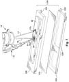
- the EBAM apparatus 10 includes at least one material delivery device 12 for delivering raw material 13 in solid state form to a feed region, and an energy source 14 (also referred to as an energy emission device 14), such as an electron beam (EB) generator (e.g., EB gun) that controllably emits at least one energy beam 16, such as an electron beam, for applying energy to liquefy the raw material delivered by the material delivery device 12 at the feed region.
- an energy source 14 also referred to as an energy emission device 14
- EB electron beam
- a work piece support 18 may be provided for receiving the liquefied raw material.
- the work piece support 18 may form a substrate, or may support a substrate, onto which the liquefied raw material is deposited as a molten pool deposit 20.
- the liquefied raw material in the molten pool deposit 20 solidifies to form a re-solidified layer 22 (shown in Fig. 3 , for example), which thereby becomes the substrate upon which additional re-solidified layers are formed.
- the EBAM apparatus 10 may build upon each re-solidified layer to form a three-dimensional article layer-by-layer.
- the raw material 13 is a metal wire, which may be fed with the material delivery device 12 via an actuator or other suitable device at a controlled feed rate.
- the wire may be fed into the molten pool 20 established by the electron beam 16 though a suitable guide nozzle 24.
- the distance between the electron beam 16 and the molten pool 20 of the additively manufactured article may be controlled, along with the feed rate, such that the raw material 13 being deposited is a generally continuous stream of material from the feed wire to the molten pool deposit 20, so as to avoid droplets or other discontinuities, or to avoid accumulation and premature solidification.
- the material delivery device 12 may accommodate wire feed rates up to about 300 inches per minute (IPM) with wire diameters ranging from about 0.030 inches to about 0.156 inches, or more.
- the material delivery device 12 may be adjustable for feeding relatively large or relatively small diameter wires, for example, wire diameters below about 7 mm, below about 5 mm, or below about 3 mm, or below about 1 mm.
- the material delivery device 12 may be adjustable for feeding the wire at relatively high and relatively low feed rates, for example, below about 300 IPM, below about 200 IPM, below about 100 IPM, or below about 50 IPM.
- the raw material 13 is the aluminum alloy precursor material having the composition(s) described above (e.g., Table 1), which may be utilized for forming an article having an aluminum 6061 alloy composition (e.g., Table 2). It is understood, however, that in one or more other disclosures not forming part of the present invention, the raw material 13 may include one or any combination of metals or alloys (e.g., metals including a transition metal or an alloy thereof).
- the raw material 13 may include one or more of titanium, aluminum, iron, nickel, chromium, cobalt, stainless steel, niobium; tantalum, copper, bronze, brass, beryllium, copper, vanadium, or tungsten.
- Disclosures of raw materials not according to the present invention include aluminum or other aluminum alloys, such as Al 6061 or other aluminum alloys (e.g., 6xxx-series having Mg and Si; 2xxx-series having Cu; and 7xxx-series having Zn).
- the energy beam generation device 14 may expose the raw material 13 to sufficient energy to heat the raw material beyond its melting point (e.g., beyond a temperature of a solidus line representative of the alloy composition).
- a suitable electron beam gun may provide energy in the form of a stream of focused electrons accelerated towards the raw material in the feed region by a relatively high voltage potential (e.g., greater than about 15 kilovolts, such as about 30 kilovolts, about 60 kilovolts, about 100 kilovolts, or even about 150 kilovolts, or higher).
- the electrons may be generated within the EB gun via one or more heated filaments.
- the power output of the EB gun typically may be controlled by limiting or throttling the flow of electrons toward the feed region.
- beam current may be greater than about 50, 100, 200, 300, 400 milliamps or more.
- the total power output level of the emitted electron beam may be about 1 kilowatt to about 30 kilowatts, for example, greater than about 1, 2, 4, 6, 8, 10, 20 kW or more.
- One approach to the operation of an electron beam gun may be to maintain the parameters of the gun at a sufficient level so that the maximum depth of a molten pool deposit may be maintained substantially constant at a depth less than about 3 cm, such as about less than about 1 cm, and possibly even less than about 0.5 cm.
- the electron beam generation device 14 may be controllably operated and may include a suitable mechanism for directing the location of an emitted energy beam 15, which may thereby be directed at point locations such that two or more preselected power densities can be applied over two or more preselected regions. It is possible that the emitted energy beam 15 may be operated in a generally defocused mode, a generally focused mode, or both. In an exemplary embodiment, the emitted energy beam 15 may be operated in a mode that maintains a generally constant focus of the beam, which is deflected and translated during subsequent raster frames.
- a beam having a width of about 0.5 to about 0.8 mm may be rastered to cover an effective width of about 1.0, 2.0, 3.0 mm, 10 mm, or larger.
- a relatively large amount of energy may be dispersed over a relatively large area, but to a relatively shallow depth, as compared with traditional electron beam welding.
- One approach for utilizing such rastering may involve the use of an electron beam generating device that provides for focusing and/or deflecting the electron beam, and directing point location, by using one or more deflection coils, such as one or more programmable electromagnetic coils 26.
- the step of emitting the electron beam 15 during successively repeating steps may include emitting the beam using a substantially constant clock rate throughout the repeating steps, and the translating of the electron beam may include deflecting the beam with the one or more electromagnetic coils 26.
- the translating step may include translating from point to point at a substantially constant clock rate, and throughout the steps a substantially constant frame rate may be employed.
- the operation of the EB gun may be configured so that there is synchronicity between the programmed beam raster path and one or more control signals.
- a suitable control system may control the operation of the electron beam generating device such as its power, current, voltage, beam characteristic, or any combination thereof.
- the emitted energy beam 15 may be rastered to form one or more beam patterns.
- the emitted energy beam 15 may be deflected and translated through a raster pattern to include a leading energy beam pattern 16a defined by a leading energy beam 16, and a trailing energy beam pattern 17a defined by a trailing energy beam 17. It is understood that although shown as two separate and simultaneous energy beams 16, 17, the rastering of the single emitted beam 15 is translated from point to point to define the respective patterns 16a, 17a.
- the leading energy beam 16 e.g.
- leading energy beam pattern 16a) and the trailing energy beam 17 may refer to the respective beams as provided by such rastering.
- the rastering of the emitted beam 15 may, during one or more individual frames, transfer a differential in density of heat delivered per unit time as between at least two regions of a frame, such as a differential in power level or power density as between at least two regions. In this manner, the distribution of the total power level of the emitted beam 15 may be split between the leading energy beam 16 and the trailing energy beam 17, or the power density applied over the area defined by the respective patterns 16a, 17a may be split.
- the total power level may be split between the leading energy beam (L) and the trailing energy beam (T) by a ratio (L:T) of about 25:75, 50:50, 60:40, 70:30, 75:25, 80:20, 85:15, 90:10, 95:5, 96:4, 97:3, 98:2, or 99:1, including all subranges therebetween.
- L:T ratio of about 25:75, 50:50, 60:40, 70:30, 75:25, 80:20, 85:15, 90:10, 95:5, 96:4, 97:3, 98:2, or 99:1, including all subranges therebetween.
- the at least two separate regions may be exposed to at least two separate energy beams (e.g., 16, 17), which may be emitted from at least two different energy sources, and which may form respective patterns (e.g., 16a, 17a) in any suitable manner.
- the work piece support 18, the electron beam generator 14, and/or the material delivery device 12 may be positionally translatable relative to each other.
- the energy beam e.g., 15, 16, 17
- the travel speed may be relatively fast or relatively slow, for example, 10 IPM or more, such as 15 IPM, 25, IPM, 50 IPM, or 100 IPM, or more.
- the energy beam generation device 14 may be translatable in a plurality of axes (e.g., 3, 4, 5 or 6 axes) relative to the work piece support 18 (the latter of which may itself be fixed or translatable).
- the energy beam e.g., leading energy beam
- the energy beam generation device 14 may be fixed in position, and the work piece support 18 may be moved to various positions relative to the energy beam generation device.
- a suitable housing defining a chamber 28 may be employed to enclose at least the material delivery device 12, the electron beam generator 14, and/or the work piece support 18.
- the chamber 28 may be configured as a vacuum chamber, which may be evacuated as desired for processing.
- the pressure may be evacuated with one or more suitable vacuum pumps so that the pressure within the chamber ranges from about 5,000 microtorr to about 30 microtorr, or lower, such as about 4,000 microtorr, 3,000 microtorr, 2,000 microtorr, 1,000 microtorr, 500 microtorr, 100 microtorr, or lower.
- a suitable vacuum pumping arrangement utilizing a combination of mechanical and oil diffusion pumps may be used.
- the chamber 28 may be such that it provides for suitable vacuum sealing and radiation shielding, and is sufficiently large to house the components necessary for work piece manufacture.
- a stainless steel chamber may be employed.
- the internal chamber dimensions may be at least about 48 in. ⁇ 48 in. ⁇ 60 in., such as about 68 in. ⁇ 68 in. ⁇ 92 in. (L ⁇ W ⁇ H), or about 48 in. ⁇ 48 in. ⁇ 228 in. (L ⁇ W ⁇ H), or more.
- one or more sensors may be provided for receiving information about one or more processing parameters, or parameters associated with the additively manufactured article.
- processing parameters may include, but are not limited to, wire feed rate, travel speed, position, temperature, power level, voltage potential, beam current, rastering, radiation, etc.
- a control system 20 with a suitable controller may be configured to receive information from the sensors about the processing conditions, such that the controller may change an operating parameter in response to the monitored condition.
- the control system 20 may be in signal communication with one or more of the material delivery device 12, energy emission device 14, work piece support 18 and/or sensors.
- the control system 20 may control the operation of the energy emission device 14 such as its translatable position; total power level; total current level; total voltage potential; leading and/or trailing energy beam characteristic(s), including their respective beam patterns, pulsing characteristics, positional relationships, power levels, power densities, voltages, and/or currents; or any combination thereof.
- the control system 20 may receive instructions from a 3D model having fabrication instructions that, when carried out by the EBAM apparatus 10, result in the fabrication of the desired article.
- One or more of the controls and data acquisition may be electronically managed through a user interface and display device (e.g., suitable instrumentation, such as one or more computers).
- the process may be performed to fabricate a three-dimensional article (e.g., metallic article) at a rate of about 0.5 cm 3 /hr to about 3,600 cm 3 /hr, such as about 1.0, 10, 50, 100, 200, 400, 800, 1,000 cm 3 /hr, or higher.
- the process may also be performed to fabricate an article (e.g., metallic article) at a rate of at least about 2.5, 3.0, 3.3, 5 or even 10 kg/hour (e.g. having an average bead width of about 10 to about 15 mm).
- the steps may be performed at a rate sufficient to deposit the raw material as a plurality of molten pool deposits, or beads, that define successive layers having an average bead width of about 10 to about 15 mm (e.g., about 12.7 mm) at a rate of at least about 25 cm of bead per minute (e.g., about 35 to 80 cm per minute or higher).
- the process may be interrupted for a period (e.g., of at least one minute, one hour, two hours, one day, or longer) prior to completion of the article, and may be resumed after complete solidification of the article occurs.
- the EBAM apparatus 10 may include one or more components as found in the Sciaky model NG1 VX68.
- suitable components and apparatus that may be employed in the present teachings include, without limitation, a fully functioning electron beam welding and deposition system utilizing a low voltage moving gun technology, which may include six programmable CNC motion axes including XYZ linear and part rotation (R), part tilt (T), and electron beam gun tilt axes.
- An electron beam gun such as the Sciaky low voltage 60/60 style electron beam gun may be employed.
- the entire system may be programmed and controlled via Sciaky's W20XX series CMC and process controller. It is also possible that the teachings herein may employ a separate dedicated computer in addition to the NG1 system controller.
- Such computer may be configured, for example, to provide a communication link to the NG1 primary controller via Ethernet and may allow for bidirectional data transfer.
- teachings herein may utilize the apparatus and method disclosed in U.S. Application Publication No. 2011/0240607 filed February 17, 2011 , which is incorporated herein by reference in its entirety, including, but not limited to, the use of closed-loop control as described therein.
- Fig. 4 (with reference to Fig. 3 and Fig. 5 ), a flow chart illustrating an exemplary method 100 of additively manufacturing a three-dimensional article is shown.
- the method 100 has similar features to the fusion processing method 1 described above, and consequently one or more features of the method 100 may be applicable to the method 1 (or vice versa), except as noted below. It is also understood that aspects of the methods 1, 100 may be substituted for one another or used in conjunction with one another where applicable.
- the method 100 may begin before step 110 by configuring a model for the article and/or fabrication instructions for the article to be additively manufactured.
- the article model may be any computer-readable file or files on a non-transitory computer readable medium that collectively specify the structure, materials, and/or other features of the article. This may, for example include CAD files, STL files, and the like that provide three-dimensional descriptions of the article.
- Fabrication instructions corresponding to a model may be any collection of instructions that, when carried out by an additive manufacturing apparatus or three-dimensional printer, result in the fabrication of the article.
- fabrication instructions may include a series of instructions for moving to various x,y,z coordinates and controlling power level, beam current, feed rate, travel speed, or other desired parameters.
- the process 100 may be carried out using suitable digital electronic circuitry, or computer software, firmware, or hardware, as understood by those having skill in the art.
- the material deposition system 10 may receive fabrication instructions from a controller (e.g., control system 20) according to the previously described model.
- the raw material 13 is provided in solid state form.
- the raw material 13 may be a metal or metal alloy, such as the exemplary aluminum alloy precursor material (e.g., Table 1), and may be in the form of a wire, which may be fed by the material delivery device 12 at a controlled feed rate to a feed region.
- the raw material may be different materials (e.g., different metals, metal alloys, or non-metals), and may be provided in different forms (e.g., fed via a dispenser as a powder spray, or provided as a powder bed), as would understood by those having ordinary skill in the art.
- the raw material 13 is exposed to the leading energy beam 16.
- the leading energy beam 16 may be an electron beam emitted from the electron gun 14, where the leading energy beam 16 has sufficient energy to heat the raw material 13 beyond its melting point.
- the leading energy beam 16 may be derived from the emitted energy beam 15 via rastering to form the leading energy beam pattern 16a, as discussed above.
- the leading energy beam pattern 16a is a circular pattern, and more particularly may be composed of a series of concentric circles, as shown. There may be two or more concentric circles, such as 3, 6, 9, 12 or more such concentric circles.
- Other leading energy beam patterns are also possible, such as elliptical, parabolic, or polygonal patterns.
- the chamber 28 may be under vacuum.
- the energy beam is an electron beam in the illustrated embodiment, other energy beams (also referred to as direct energy sources) are possible as would be understood by those having skill in the art.
- other types of energy beams may include, but are not limited to, laser, electric arc, plasma, and the like.
- the raw material 13 is heated beyond its melting point to liquefy the raw material and form a melt pool 20.
- the melt pool 20 may be a molten pool deposit, which may be formed on a substrate.
- the melt pool 20 may be formed with the liquefied raw material as the leading energy beam 16 moves forward in a travel direction (shown with arrow) along an x-y plane relative to the substrate.
- the substrate upon which the melt pool is formed may include the work piece support 18 and/or a re-solidified layer 22, or other such substrate capable of receiving and supporting the melt pool 20.
- the process may be under inert conditions to reduce the formation of oxides in the melt pool.
- the work piece support 18 may move relative to a fixed energy beam.
- the x-y plane may be an arbitrary frame of reference, and may include one or more planes other than horizontal.
- the melt pool may be formed in a different manner or different location, for example, the melt pool may be formed in a powder bed, and may be carried out in an inert environment, such as by backfilling the chamber with an inert gas, for example, helium, argon, or other suitable gas that does not detrimentally react with the melt pool.
- the melt pool 20 includes a leading region 30 and a trailing region 32.
- the leading region 30 is proximal to the leading energy beam (e.g., leading energy beam pattern 16a), such as proximal to the region where the leading energy beam 16 impinges and liquefies the raw material 13.
- the leading region 30 of the melt pool may represent the region where fresh liquid melt is deposited (e.g., the region where the raw material is fed), and thus moves with the leading energy beam 16 along the x-y plane. Because the leading region 30 is the region where fresh liquid melt is continuously deposited, the leading region 30, and particularly the forward edge 31 of region 30, may be at a temperature that is greater than the liquidus temperature of the raw material, and thus predominantly contains a liquid phase of the raw material.
- the trailing region 32 behind the leading region 30 begins to cool and solidify.
- the melt pool 20 may be fully liquid at the leading region 30, may begin to re-solidify at a forward interface 34 of the trailing region 32, and solidification may progress through the trailing region 32 toward a rearward interface 36 of the trailing region 32 where the material may be completely re-solidified.
- the trailing region 32 may be considered to include a liquid phase interface (e.g., the forward interface 34 where the trailing region 32 interfaces with the leading region 30, and which may be representative of the liquidus isotherm of the raw material), a solid phase interface (e.g., the rearward interface 36 where the trailing region 32 interfaces with the re-solidified raw material 22, and which may be representative of the solidus isotherm of the raw material), and a transition region between the liquid phase interface 34 and the solid phase interface 36.
- a liquid phase interface e.g., the forward interface 34 where the trailing region 32 interfaces with the leading region 30, and which may be representative of the liquidus isotherm of the raw material
- a solid phase interface e.g., the rearward interface 36 where the trailing region 32 interfaces with the re-solidified raw material 22, and which may be representative of the solidus isotherm of the raw material
- the transition region between the liquid interface 34 and the solid interface 32 (which may be at a temperature between the liquidus and solidus temperatures) is the region where solidification and grain growth begins to occur in the melt pool 20, and thus contains a two-phase mixture of solid particulate and liquid metal (e.g., a solid-liquid phase).
- a volumetric change occurs during the liquid-to-solid phase change of the raw material, such that shrinkage occurs in the cooler region of the trailing region 32 near the solid interface 36.
- Strain in the melt pool caused by such shrinkage may cause porosity or openings to develop in this cooler solidifying region, and if the available supply of liquid metal is insufficient or incapable of filling these openings between the solidifying metal, then hot cracking may occur.
- the issue of hot cracking may be exacerbated by the formation of dendritic structures in the transition region of the melt pool, which may form narrow channels between solidifying grains that act to choke off or prevent the liquid metal from replenishing the reduced volume caused by solidification shrinkage.
- the additive manufacturing process 100 may be utilized to reduce hot cracking of metals or alloys.
- the trailing region 32 of the melt pool 20 is exposed to the trailing energy beam 17.
- the trailing energy beam 17 may be directed toward the forward (liquid) interface 34 of the trailing region, the rearward (solid) interface 36 of the trailing region, and/or the transition region between the interfaces 34, 36.
- the trailing energy beam 17 is configured to reduce hot cracking as the melt pool 20 solidifies. More particularly, the trailing energy beam 17 may have a power level, power density, pulsation, beam pattern, and/or positional relationship sufficient to break-up or disrupt dendritic structures in the trailing region 32 of the melt pool.
- the trailing energy beam 17 may be configured to re-heat or re-melt dendritic structures in the melt pool, which may reduce blockages in the melt pool that otherwise prevent liquid melt from replenishing the lost volume due to shrinkage.
- the trailing energy beam 17 may be configured to enhance agitation and/or redistribution of the liquid phase in the trailing region of the melt pool.
- the trailing energy beam 17 may enhance convective currents and/or induce pulsing electromagnetic fields that may generate turbulence in the trailing region of the melt pool, which may reduce the formation of dendrites, allowing for a more equiaxed grain structure, and/or which may enhance liquid metal flow to the solidifying regions of the melt pool.
- the trailing energy beam 17 may be configured to stress relieve or anneal the re-solidified raw material behind the trailing edge of the melt pool.
- the trailing energy beam 17 may have a power level or power density that is different than a power level or power density of the leading energy beam 16.
- the trailing energy beam 17 may have a trailing energy beam pattern 17a that is different than the leading energy beam pattern 16a defined by the leading energy beam 16.
- the difference in power level, power density, pulsation, beam pattern, and/or positional relationship between the trailing energy beam and leading energy beam may be provided by virtue of translating an energy beam, such as the emitted energy beam 15, through a raster pattern.
- trailing energy beam 17 may be employed, such as by having two separate energy sources that emit respective leading and trailing energy beams, each of which may be rastered, defocused, or translated to form a desired pattern.
- the trailing energy beam 17 may form a beam pattern that generally corresponds to the shape of the transition region (e.g., trailing region 32) of the melt pool 20.
- the transition region located between the liquid interface 34 and the solid interface 36 typically has a generally concave shape that opens toward the leading region 30, because the lateral edges of the melt pool 20 may cool faster than the center.
- the trailing energy beam pattern 17a may be configured in a concave pattern with the concave side toward the leading region 30 of the melt pool (as shown in Fig. 5 , for example), which may enhance the disruption of dendritic structures and/or promote redistribution of liquid melt.
- the apex of the concave pattern may be positioned at a centerline of the trailing region 32 in the travel direction.
- the trailing energy beam pattern 17a may have a lateral width that is at least as wide, or wider, than a lateral width of the trailing region 32, where the respective lateral widths are taken in a direction orthogonal to the travel direction.
- the trailing energy beam pattern 17a is chevron-shaped, which is found to be effective in reducing hot cracking during the exemplary additive manufacturing process 100.
- the trailing energy beam pattern 17a may be configured with an arc-shaped, crescent-shaped, or parabolic-shaped pattern, or other similar concave patterns, including polygonal patterns.
- the trailing energy beam 17 (e.g., the trailing energy beam pattern 17a) may be spaced apart from the leading energy beam 16 (e.g., the leading energy beam pattern 16a) at a fixed distance as the respective energy beams move together in the travel direction. As shown in the illustrated embodiment of Fig. 5 , the trailing energy beam pattern 17a may be spaced apart from the leading energy beam pattern 16a at a fixed distance such that the trailing energy beam 17 may be maintained in the transition region containing the solid-liquid phase (e.g., trailing region 32).
- fixed distance or “fixed position” when used to describe the positional relationship between the respective energy beams, or respective energy beam patterns, means that the energy beams themselves, or the patterns that are formed by the energy beams, are in such a positional relationship as they impinge the raw material, even though during rastering the emitted beam may move point-to-point to form such beams or such patterns, as understood from the discussion above.
- trailing energy beam pattern may be fixed relative to the leading energy beam pattern
- position of the trailing energy beam 17 e.g., trailing energy beam pattern 17a
- leading energy beam 16 e.g., leading energy beam pattern 16a
- the solid interface 36 is formed, and the solidified melt pool forms the re-solidified layer 22, or trace, that trails the path taken by the leading energy beam 16, leading region 30, and trailing region 32 along the x-y plane.
- these re-solidified layers 22 are deposited adjacent to each other along the x-y plane, and/or on top of each other along a z-axis that is orthogonal to the x-y plane, so as to build the three-dimensional article re-solidified layer by re-solidified layer.
- the process may repeat a number of times until the three-dimension article is formed to a desired level of completion.
- one or more of the parameters of the exemplary process 100 may be optimized to reduce hot cracking.
- one or more of the following parameters may be varied in an EBAM process for optimization: wire feed rate, total emitted beam power, and power distribution between the leading energy beam and the trailing energy beam.
- the wire feed rate is the rate at which the raw material wire is fed to the feed region;
- the total emitted beam power is the total power level of the emitted electron beam from the source, which is translated through a raster pattern to define the leading energy beam and the trailing energy beam;
- the power distribution is the split of the total power level between the leading energy beam and the trailing energy beam.
- one or more of the following parameters may be constant during optimization of the EBAM process: travel speed (e.g., relative speed between the EB gun and substrate), accelerating voltage of the electron beam, wire diameter, wire composition, size of the deposited specimens, and interpass temperature.
- travel speed e.g., relative speed between the EB gun and substrate
- accelerating voltage of the electron beam e.g., relative speed between the EB gun and substrate
- wire diameter e.g., wire composition
- size of the deposited specimens e.g., interpass temperature.
- one or more of the following observations may be made: visual inspection of external segregation defects (e.g., macro-cracking), mechanical testing (e.g., tensile and hardness testing), radiographic inspection of internal segregation defects (e.g., internal porosity), and compositional analysis of the deposited and re-solidified raw material (e.g., spark emission spectroscopy).
- visual inspection of external segregation defects e.g., macro-
- the following constant parameters are used to additively manufacture test specimens: (i) the travel speed is about 15 inches per minute, (ii) the accelerating voltage is about 30kV, (iii) the wire diameter is about 0.125 inches, (iv) the wire composition is aluminum 6061 alloy, (v) the vacuum level is less than about 100 microtorr (vi) the leading energy beam pattern is a series of nine concentric circles, (vii) the trailing energy beam pattern is chevron-shaped, (viii) the trailing energy beam pattern is directed at the trailing region of the melt pool, and is at a fixed distance relative to the leading energy beam pattern, (ix) the interpass temperature is less than about 30 degrees Celsius, and (x) the size of the deposited specimen is about 8 in.
- the results of the optimization experiment indicate that one or more of following parameters may be optimal for electron beam additively manufacturing the aluminum 6061 alloy: (i) the total power level is in the range of about 1kW to about 10kW, more particularly in the range of about 2 kW to about 5 kW (with a beam current in the range of about 80 mA to about 143 mA, for example), (ii) the distribution of the total power level is split between the leading energy beam (L) and the trailing energy beam (T) by a ratio in the range of about 85:15 (L:T) to about 99:1 (L:T), and (iii) the wire feed rate is in the range of about 30 inches per minute to about 55 inches per minute.
- the total power level is in the range of about 1kW to about 10kW, more particularly in the range of about 2 kW to about 5 kW (with a beam current in the range of about 80 mA to about 143 mA, for example)
- the distribution of the total power level is split between the leading energy beam (L) and
- the results of the optimization experiment indicate that the following parameters of the EBAM process create specimens that have the fewest cracks and porosity by visual and radiographic observation, and have the highest tensile strength results: (i) the total power level is in the range of about 2kW to about 3kW, more particularly about 2.7 kW, (ii) the distribution of the total power level is split between the leading energy beam (L) and the trailing energy beam (T) by a ratio of about 95:5 (L:T), and (iii) the wire feed rate is about 40 inches per minute.
- the results of compositional analysis (e.g., spark emission spectroscopy) of the fabricated specimens indicate that the weight percentage of magnesium and zinc are reduced during the EBAM process, which causes the fabricated articles to fall outside of the prescribed compositional specifications for Al 6061 alloy (e.g., Table 2), more particularly outside the prescribed limits for magnesium.
- the prescribed compositional specifications for Al 6061 alloy e.g., Table 2
- magnesium is an alloying agent that contributes to strength of the alloy, particularly during subsequent heat treatment.
- Zinc may be a tramp element found in the aluminum alloy (e.g., not added for performance), but its loss during the EBAM process may contribute to porosity of the solidified specimen, which may thus reduce strength.
- alloying agents e.g., Mg
- tramp elements e.g., Zn
- the processing temperature of the Al 6061 alloy is beyond its melting point (so as to form the melt pool), which may be in the range of about 580 degrees Celsius (solidus) to about 652 degrees Celsius (liquidus).
- the vapor pressure of magnesium is typically greater than 100 microtorr (e.g., the vapor pressure of magnesium at 652 degrees Celsius is about 3.4 torr).
- the pressure level in the EBAM chamber during additive manufacturing is traditionally set to below 100 microtorr.
- the elevated processing temperature e.g., 580 degrees Celsius to about 652 degrees Celsius
- the low pressure environment e.g., below 100 microtorr
- elements in the aluminum 6061 alloy such as magnesium and zinc.
- the vacuum level used during an exemplary additive manufacturing process may be decreased compared to traditional EBAM processing parameters, bringing the pressure level closer to atmospheric pressure (but still below atmospheric pressure) so as to prevent or reduce vaporization of one or more alloying agents during the additive manufacturing process, which may thereby reduce hot cracking and/or reduce internal porosity in the additively manufactured article.
- the vacuum chamber may be set to a pressure level during the additive manufacturing process that is closer to, equal to, or greater than the vapor pressure of the one or more alloying agents at the processing temperature to reduce vaporization thereof.
- additive manufacturing processes may be limited to a maximum pressure level in the vacuum chamber based on limitations of the additive manufacturing process/apparatus.
- increasing the pressure level to greater than 3,000 microtorr may affect electron beam characteristics (e.g., increased attenuation of the electron beam caused by a scattering effect of the atmosphere in the chamber), or may affect EB gun discharging (e.g., metal vapor or positive ions entering the EB gun and causing electric arcs that may lead to breakdown or interruption during the process).
- the vacuum chamber may be back-filled with an inert gas, such as helium
- an experiment is conducted that increases the pressure level of the vacuum chamber (closer to atmospheric pressure) during an exemplary EBAM process when compared to a traditional EBAM process that uses a chamber pressure of less than 100 microtorr.
- the exemplary EBAM process is used to fabricate Al 6061 (having at least Mg as an alloying agent), and the processing temperature of the raw material is in the range of about 580 degrees Celsius to about 652 degrees Celsius.
- the pressure level of the chamber is set to about 500 microtorr or greater. More particularly, so as to reduce the likelihood of discharging of the EB gun, the pressure level in the vacuum chamber is in the range of about 500 microtorr to about 3,000 microtorr.
- the pressure level in the vacuum chamber is in the range of about 1,000 microtorr to about 3,000 microtorr, or more particularly in the range of about 2,000 microtorr to about 3,000 microtorr. Additionally, the vacuum chamber is back-filled with helium. The results of this experiment indicate that such an exemplary process is effective to reduce vaporization of alloying agents, such as magnesium, which reduces porosity and improves compositional control of the additively manufactured specimens.
- the trailing energy beam 17 may be fixed relative to the leading energy beam 16 (e.g., leading energy beam pattern 16a); however, it is understood that in other exemplary embodiments it may be advantageous for the trailing energy beam 17 (e.g., the trailing energy beam pattern 17a) to instead be dynamically adjusted during the additive manufacturing process 100. Such dynamic adjustment of the trailing energy beam 17 may enhance agitation of the melt pool 20 at the trailing region 32 by promoting convective currents or turbulence from pulsing electromagnetic fields in the melt pool which may provide a stirring effect.
- Such a process may disrupt dendritic structures and encourage a more equiaxed grain structure in the trailing region 32, and/or may enhance redistribution of liquid melt from the leading region 30 toward the trailing region 32 so as to replenish lost volume caused by shrinkage as the melt pool solidifies. This may reduce hot cracking, reduce internal porosity, and/or improve strength and ductility in the additively manufactured article.
- the trailing energy beam 17 may be dynamically altered by varying the distance from the leading energy beam 16 (e.g., the leading energy beam pattern 16a) as the leading energy beam moves in the travel direction.
- the trailing energy beam 17 may move back and forth in the melt pool 20 between a first position (e.g., that is closer to the leading energy beam 16, such as at or near the region of the liquid interface 34) and a second position (e.g., that is further from the leading energy beam 16, such as at or near the region of the solid interface 36); and/or may move to one or more intermediate positions between the first position and the second position.
- the trailing energy beam 17 may cycle between two or more positions located at varying distances from the leading energy beam 16.
- the trailing energy beam 17 may move in various other directions, such as side-to-side (e.g., laterally in a direction orthogonal to the travel direction), or may rock back and forth about a pivot point, for example.
- Such dynamic movement(s) of the trailing energy beam 17 may locally heat different regions of the melt pool causing density gradients that may promote convective or turbulent stirring, and/or which may enhance agitation by pulsing electromagnetic fields at the different regions.
- the trailing energy beam may alternate between several positions in such a way to promote movement of liquid melt in the direction opposite the general travel direction so as to encourage movement of fresh melt toward the solidifying regions of the melt pool (e.g., toward the rearward (solid) interface 36) in order to replenish material as shrinkage and contractions occur.
- Fig. 6 illustrates an exemplary method 200 of dynamically altering the position of the trailing energy beam 17 (e.g., the trailing energy beam pattern 17a) relative to the leading energy beam 16 (e.g., the leading energy beam pattern 16a) during a manufacturing process. It is understood that this method 200 may be incorporated into the method 100 described above, such as at step 150. As shown in Fig. 6 , the trailing energy beam pattern 17a may be spaced from the leading energy beam pattern 16a at progressively increasing distances (d1-d4) for each time interval (t1-t4), and then may cycle back through each interval.
- each progressively increasing distance is from the leading region 30 toward the trailing region 32, which may encourage the liquid melt in the leading region 30 to move rearward toward the solidifying portions of the trailing region 32 (e.g., toward the rearward (solid) interface 36 of the trailing region).
- the trailing energy beam 17a may dwell for a period of time at each interval (t1-t4) so as to produce a density gradient in the melt pool that may enhance movement and inertia of the liquid metal, which may promote stirring and/or encourage liquid metal to redistribute toward the solidifying regions.
- the trailing energy beam pattern 17a may be deactivated at one or more of the time intervals, such that only the leading energy beam pattern 16a is utilized. It is understood that at each time interval shown, the leading energy beam 16a and subsequent formation of the melt pool moves along the substrate 18 in the travel direction (shown with arrows), such that the re-solidified layer increases in size at each time interval (as shown).
- an experiment is conducted that utilizes the method 200 for electron beam additive manufacturing of aluminum alloy 6061.
- an electron beam gun emits an electron beam, which is translated through a raster pattern to form the leading energy beam pattern 16a and the trailing energy beam pattern 17a.
- the electron beam gun scans at a rate of 400Hz, and the series of patterns (t0-t4) is repeated every 100 cycles.
- t0 scans 1-20
- the trailing energy beam pattern 17a is deactivated and only the leading energy beam pattern is utilized.
- the trailing energy beam pattern 17a is spaced by a first distance d1, which is one-fourth of a maximum distance as represented by second distance d4 (shown at t4). It is understood that the maximum distance as used herein is not necessarily a maximum possible distance, but is an arbitrary designation of the maximum amount the beams are spaced apart during this process.
- the trailing energy beam pattern 17a is spaced by a first intermediate distance d2 between d1 and d4, where the distance d2 is at half of the maximum distance d4.
- the trailing energy beam pattern 17a is spaced by a second intermediate distance d3, which is at three-fourth of the maximum distance d4.
- the trailing energy beam pattern 17a is spaced at the maximum distance d4. This process then repeats for the desired number of cycles as the layer 22 is formed.
- the results of this experiment indicate that the process 200 is effective to further reduce porosity, further increase strength (e.g., ultimate tensile strength), and further increase ductility of the additively manufactured specimen when compared to a similar EBAM process that uses the trailing energy beam at a fixed distance as discussed above.
- the results also indicate that such a dynamic trailing energy beam may be effective to reduce volatilization of alloying agents, such as magnesium, which may be due to the stirring effect.
- varying distances or “varying positions,” or such similar terms used to describe positional relationships between the respective energy beams, or respective energy beam patterns, means that the energy beams themselves, or the patterns that are formed by the energy beams, are in such positional relationships as they impinge the raw material, understanding that during a rastering method the emitted beam may already be moving point-to-point to form such beams or such patterns.
- the advantages provided by the dynamic alteration(s) of the trailing energy beam as discussed above are not limited to the trailing energy beam being configured in a concave pattern as shown, but rather it is contemplated that advantages may be realized using various other trailing energy beam patterns, such as circular, concentric circles, elliptical, polygonal, etc. It is also understood that varying the position of the trailing energy beam may be one of many different ways to dynamically alter the trailing energy beam to enhance agitation/redistribution in the melt pool, and other such methods of dynamic alteration may include one or more of: varying the intensity of the trailing energy beam (e.g., the energy level or power density), varying the pattern of the trailing energy beam, and other similar dynamic variations.
- varying the intensity of the trailing energy beam e.g., the energy level or power density
- FIG. 7 another exemplary embodiment of a work piece support 318 for the exemplary EBAM apparatus 10 is shown.
- the work piece support 318 is substantially similar to the above-referenced work piece support 18, and consequently the foregoing description of the work piece support 18 is equally applicable to the work piece support 318, except as noted below.
- the work piece support 318 may form a substrate for supporting the liquefied raw material as a molten pool deposit 20, either directly or indirectly via the one or more re-solidified layers 22. In this manner, the substrate formed by the work piece support 318 provides a heat transfer medium for extracting heat from the molten pool deposit 20, or from the re-solidified layers 22, or both. Because the EBAM process typically occurs under vacuum, there is no convective heat transfer available to cool the melt pool 20, re-solidified layers 22, or substrate (e.g., substrate support 320), and thus heat may uncontrollably accumulate in the substrate. This accumulation of heat in the substrate may affect the interpass temperature, which is the temperature of the substrate in the feed region just before a subsequent molten pool deposit is made. The interpass temperature may affect the characteristics of the molten pool deposit 20 and/or the re-solidified layer 22, and thus it may be advantageous to control the interpass temperature.
- the work piece support 318 includes a chill plate 324, which is operatively coupled in thermal communication with the substrate support 320.
- a compressible thermally conductive material 322 may be interposed between the chill plate 324 and the substrate support 320.
- the thermally conductive material 322 may be Grafoil (self-adhering graphite particles) manufactured by Graftech International of Parma, Ohio.
- the compressible thermally conductive material e.g., Grafoil
- the chill plate 324 may include fluid passages 326, which may be fluidly coupled via fluid conduits 328 to a source of chilled fluid, such as water, for actively and continuously cooling the chill plate 324 as the chill plate extracts heat from the substrate support 320.
- a source of chilled fluid such as water
- One or more sensors 329 such as a thermocouple, may be embedded in one or more of the regions of the work piece support 318 to monitor temperature, and the active cooling of the chill plate 324 may be controlled, such as by the control system 20, in response to the measured temperature.
- the chill plate 324 may be configured to maintain a relatively constant interpass temperature of the substrate during the EBAM process, such as at about 200, 100, or 65 degrees Celsius or less, for example.
- the exemplary fusion processing method(s) (e.g., 1, 100, 200) described hereinabove may be used to form an article, such as a welded or three-dimensional article, preferably made from a metal or metal alloy, such as aluminum 6061 alloy.
- the article may be an aircraft component, a rocket component, a marine component, a spacecraft component, an automotive vehicle component, a turbine component, a radar component, or component capable of functioning in any similar application.
- the exemplary process may enable near net shape of parts at least as large as 4ft. x 4ft. x 19 ft., or larger.
- the exemplary process may reduce machining time, may decrease turnaround time, may enable larger structures to be made into smaller modular structures, may reduce costs, and may produce parts that are fully-annealed through the e.g., EBAM process, which may be less susceptible to warpage after the process.
- EBAM process airborne mine neutralization system
- the exemplary additive manufacturing process described above may realize a 57% cost savings in machining compared to conventional forming of the AMNS, may provide a 97% reduction in material removed, and may realize a 62% savings in machining time.
- inventive composition(s) and method(s) are illustrated in the following examples. These examples (and the foregoing examples) are provided for illustrative purpose and are not considered limitations on the scope of inventive compositions and methods.
- test specimens are prepared by electron beam additive manufacturing in accordance with the method(s) (e.g., 100, 200) described above.
- the following constant parameters are used to additively manufacture the test specimens: (i) the travel speed is about 15 inches per minute, (ii) the accelerating voltage is about 30kV, (iii) the total power level is in the range of about 1.5kW to about 3kW, (iv) the distribution of the total power level is split between the leading energy beam (L) and the trailing energy beam (T) by a ratio of about 95:5 (L:T), (v) the wire feed rate is about 40 inches per minute (vi) the wire diameter is about 0.125 inches, (vii) the leading energy beam pattern is a series of nine concentric circles, (viii) the trailing energy beam pattern is chevron-shaped, (ix) the interpass temperature as measured at the substrate plate is less than about 28 degrees Celsius, and (x) the size of the deposited specimen is about 8 in. ⁇ 0.75 in. ⁇ 2 inch.
- Test Specimen Wire Composition (Mg) Chamber Pressure Trailing Beam Configuration 4-1 1 ⁇ 100 ⁇ Torr Static 4-2 1 ⁇ 100 ⁇ Torr Dynamic 4-3 1 >2000 ⁇ Torr Static 4-4 1 >2000 ⁇ Torr Dynamic 4-5 2 ⁇ 100 ⁇ Torr Static 4-6 2 ⁇ 100 ⁇ Torr Dynamic 4-7 2 >2000 ⁇ Torr Static 4-8 2 >2000 ⁇ Torr Dynamic 4-9 3 ⁇ 100 ⁇ Torr Static 4-10 3 ⁇ 100 ⁇ Torr Dynamic 4-11 3 >2000 ⁇ Torr Static 4-12 3 >2000 ⁇ Torr Dynamic
- the composition of the aluminum alloy precursor material is varied. More particularly, the precursor material for preparing each specimen is formed as an aluminum alloy in wire form having a composition according to Table 1, except that the magnesium content of some specimens is varied to have about 1 wt.%, about 2 wt.%, or about 3 wt.% of magnesium present in the alloy as indicated in Table 3. To accommodate for this change in magnesium content for each precursor aluminum alloy, the balance of aluminum in each precursor aluminum alloy is modified accordingly (e.g., 1 wt.%, 2 wt.%, or 3 wt.% less aluminum, respectively), with the other elements for each precursor alloy being within the ranges specified in Table 1.
- the pressure level of the EBAM chamber is varied. More particularly, during the additive manufacturing of some specimens, the pressure level is set to about 100 microtorr or less, and for other specimens the pressure level is set to about 2,000 microtorr or more with the chamber back-filled with helium.
- the configuration of the trailing energy beam is varied. More particularly, during the additive manufacturing of some specimens, the trailing energy beam is directed toward the trailing region of the melt pool and is fixed (e.g., static) relative to the leading energy beam in accordance with the method 100 described in reference to Figs. 4 and 5 above. On the other hand, during the additive manufacturing of other specimens, the trailing energy beam is dynamically adjusted (e.g., dynamic) by varying the distance from the leading energy beam in accordance with the method 200 described in reference to Fig. 6 above.
- the electron beam gun scans at a rate of 400Hz, and the series of patterns (t0-t4) is repeated every 100 cycles.
- t0 scans 1-20
- the trailing energy beam pattern is deactivated and only the leading energy beam pattern is utilized.
- the trailing energy beam pattern 17a is spaced by a first distance d1, which is one-fourth of a maximum distance as represented by second distance d4 (shown at t4).
- t2 (scans 41-60), the trailing energy beam pattern 17a is spaced by a first intermediate distance d2 between d1 and d4, where the distance d2 is at half of the maximum distance d4.
- the trailing energy beam pattern 17a is spaced by a second intermediate distance d3, which is at three-fourth of the maximum distance d4.
- the trailing energy beam pattern 17a is spaced at the maximum distance d4. This process then repeats for the desired number of cycles as the layer 22 is formed.
- each test specimen as deposited was stress relieved at 177 degrees Celsius for 4 hours, then machined into testing samples, and then heat treated by solution annealing at 529 degrees Celsius for 1 to 3 hours, water quenching, and artificially aging at 177 degrees Celsius for 8 to 10 hours per the specifications of SAE AMS 2770 for Al 6061 alloy with T6 heat treatment (incorporated by reference). Following heat treatment, each test specimen is then examined and tested as discussed in further detail below.
- Table 4 Radiographic Inspection Results of Test Specimens Test Specimen Pore Count 4-1 100 4-2 0 4-3 100 4-4 0 4-5 100 4-6 0 4-7 80 4-8 0 4-9 40 4-10 30 4-11 2 4-12 1
- Fig. 8 shows the results of the crack and pore count determination versus magnesium content.
- the results indicate that those samples with a higher magnesium content (e.g., higher weight percent in the precursor alloy) exhibit fewer cracks and pores. This is believed to be due to the loss of magnesium during the high-energy, in vacuum, additive manufacturing process leading to vaporization of the magnesium, where those samples with enriched magnesium content were able to accommodate for this loss and exhibited fewer pores.
- Fig. 9 shows the results of the crack and pore count determination versus trailing energy beam configuration. The results indicate that those samples additively manufactured with a dynamic trailing energy beam exhibit fewer cracks and pores than those samples additively manufactured with a static trailing energy beam. It is believed that the dynamic trailing energy beam promotes stirring via convective currents and/or electromagnetic forces, which enhances replenishment of liquid melt to the solidifying regions and/or restricts loss of high vapor pressure constituents, thereby reducing cracks and pores.
- Fig. 10 shows the results of the crack and pore count determination versus EBAM chamber pressure level. The results indicate that those samples additively manufactured with a pressure level of 2,000 microtorr or greater exhibit fewer cracks and pores than those samples additively manufactured with a pressure level of 100 microtorr or less. It is believed that the lower chamber pressures results in an increased amount of the high vapor pressure constituents (e.g., magnesium and zinc) being lost during the additive manufacturing process, which increases porosity.
- the high vapor pressure constituents e.g., magnesium and zinc
- Fig. 11 shows the results of ultimate tensile strength versus the variables of magnesium content, chamber pressure, and trailing energy beam configuration.
- the threshold level indicated at 42.0 ksi is considered a minimum strength requirement in accordance with ASTM B209.
- the results in Fig. 11 indicate that those samples with a higher magnesium content (e.g., higher weight percent in the precursor alloy) exhibit increased ultimate tensile strength.
- magnesium is an alloying element that contributes to strength, particularly after subsequent heat treatment of 6000-series aluminum alloys. It is also understood that samples with higher magnesium and less porosity content exhibit higher strength.
- FIG. 11 also illustrates that the trailing beam configuration has a strong influence on strength, and those samples additively manufactured with a dynamic trailing energy beam exhibited greater strength than those samples additively manufactured with a static trailing energy beam. It is believed that the enhanced stirring effects provided by the dynamic trailing energy beam results in this increased strength. As shown, Fig. 11 also shows an increase in strength for those samples additively manufactured with a pressure level of 2,000 microtorr or greater exhibit compared to those samples additively manufactured with a pressure level of 100 microtorr or less.
- Fig. 12 shows the results of elongation versus the variables of magnesium content, chamber pressure, and trailing energy beam configuration.
- the threshold level indicated at 10% elongation is considered a minimum elongation requirement in accordance with ASTM B209 (e.g., in the thickness range of 0.250 - 0.499 in.).
- the results in Fig. 12 indicate that those samples with a higher magnesium content (e.g., higher weight percent in the precursor alloy) exhibit increased elongation.
- Fig. 12 also illustrates that the trailing beam configuration has a strong influence on elongation, and those samples additively manufactured with a dynamic trailing energy beam exhibited greater elongation than those samples additively manufactured with a static trailing energy beam.
- Fig. 12 also shows an increase in elongation for those samples additively manufactured with a pressure level of 2,000 microtorr or greater exhibit compared to those samples additively manufactured with a pressure level of 100 microtorr or less.
- test specimen is tested via spark emission spectroscopy for determination of composition, and specifically for magnesium content, for each additively manufactured test specimen. The results of these tests are found in Table 6. The averages from the results in Table 6 for each varied parameter is summarized in Fig. 13 .
- Table 6 Compositional Analysis Results of Test Specimens while only test specimens 4-9 and 4-11 are according to the inventive method Test Specimen Mg Wt.% After Deposition 4-1 0.28 4-2 0.25 4-3 0.33 4-4 0.45 4-5 0.70 4-6 1.09 4-7 0.69 4-8 1.11 4-9 1.18 4-10 1.61 4-11 1.19 4-12 1.66
- Fig. 13 shows the results of spark emission spectroscopy compositional analysis versus the variables of starting magnesium content, chamber pressure, and trailing energy beam configuration.
- the lower threshold level indicated at 0.8 wt.% Mg is considered a minimum magnesium content
- the upper threshold level indicated at 1.2 wt.% Mg is considered a maximum magnesium content, in accordance with the compositional specification of Al 6061 alloy per Aluminum Association International Alloy Designations and Chemical Composition Limits for Wrought Aluminum and Wrought Aluminum Alloys -- 2015 (as illustrated in Table 2).
- the results in Fig. 13 indicate that those samples with a higher magnesium content (e.g., higher weight percent in the precursor alloy) exhibit increased magnesium content in the processed alloy.
- Fig. 13 also illustrates that the trailing beam configuration has a strong influence on final composition, and the average magnesium content of samples additively manufactured with a dynamic trailing energy beam is higher than the average of samples deposited with the static chevron. As shown in Fig. 13 , the average magnesium content of those samples processed with the dynamic trailing energy beam is within the specified compositional limits of Al 6061 alloy. It is believed that the enhanced stirring provided by the dynamic trailing energy beam results in this effect. Fig. 13 also shows a higher average magnesium content for those samples additively manufactured with a pressure level of 2,000 microtorr or greater exhibit compared to the average of those samples additively manufactured with a pressure level of 100 microtorr or less.
- composition(s), method(s) and apparatus(es), particularly for fusion processing materials that are susceptible to hot cracking have been described herein.
- an aluminum alloy precursor composition and/or method for fusion processing is provided which reduces hot cracking, improves compositional control, reduces porosity, and/or enhances the strength and ductility of the fusion processed article.
- the precursor material and fusion process using the same may be utilized for forming an article that meets compositional specifications for aluminum 6061 alloy, while minimizing defects and meeting or exceeding desired strength and ductility requirements.
- the fusion process may include a leading energy beam for liquefying the raw material to form a melt pool, and a trailing energy beam directed toward a trailing region of the melt pool.
- the trailing energy beam may be configured to enhance agitation and/or redistribution of liquid in the melt pool to prevent hot cracking, reduce porosity, or improve other characteristics of the solidified part.
- the method also may improve processing parameters, such as adjusting vacuum level to prevent volatilization of alloying agents, among other considerations.
- EBAM electron beam additive manufacturing
- the exemplary fusion process(es) described above may be equally applicable to welding techniques, such as laser beam welding, electron beam welding, and/or arc welding (such as gas metal arc welding, gas tungsten arc welding, plasma arc welding, shielded metal arc welding, hybrid arc-laser welding, etc.); or to other additive manufacturing techniques, such as direct energy deposition AM processes, including direct metal deposition, laser deposition wire, laser deposition powder, laser consolidation, laser engineering net shape, electron beam direct melting; powder bed fusion AM processes, including direct metal laser sintering, selective laser sintering, selective laser melting, electron beam melting; and other fusion processes, for example those in which a melt pool is produced and solidified.
- welding techniques such as laser beam welding, electron beam welding, and/or arc welding (such as gas metal arc welding, gas tungsten arc welding, plasma arc welding, shielded metal arc welding, hybrid arc-laser welding, etc.); or to other additive manufacturing techniques, such as direct energy deposition AM processes, including
- the exemplary fusion process(es) described above may be used for Selective Laser Sintering (SLS) and Selective Laser Melting (SLM), which are laser-based AM processes that utilized powdered materials.
- SLS Selective Laser Sintering
- SLM Selective Laser Melting
- the laser (energy beam) is traced along an x-y plane across a powder bed (raw material) of evenly spread material laid down by a leveler or roller on a build tray. As the laser interacts with the surface of the powdered material, the powder particulates melt to form a melt pool that enables the particles to fuse together to form a solid.
- a trailing laser may follow the leading (primary) energy beam, and may be directed toward a trailing region of the melt pool.
- the leading laser beam and/or trailing laser beam may have each have a pattern, and may be spaced apart at a fixed distance, or variable distance, among other factors described above.
- the powder bed drops incrementally and a roller smooths the powder over the surface of the bed prior to the next pass of the laser for the subsequent layer to be formed and fused with the previous layer.
- the build chamber may be sealed to maintain an inert gas environment to shield the melting powder from oxygen contamination. Once finished, the excess powder is removed, leaving the final additively manufactured part.
- the powder bed serves as an in-process support structure for overhangs and undercuts, and, therefore, complex shapes with high geometrical accuracy can be manufactured with this type of process.
- the exemplary fusion process(es) described above may be used for Electron Beam Melting (EBM), which is another powder bed fusion technique similar to SLM/SLS.
- EBM Electron Beam Melting
- the difference is the heat source or energy beam, which in the EBM process uses an electron beam, rather than a laser.
- the process is carried out under vacuum conditions.
- a heated tungsten filament emits electrons which are collimated and accelerated to form the electron beam (energy beam).
- the electron beam is controlled by two magnetic coils.
- the first coil is a magnetic lens which focuses the beam, and the second coil assembly deflects the focused beam to a desired point on the build platform.
- the emitted electron beam may be translated through a raster pattern to form a leading energy beam and a trailing energy beam as described above.
- a metal powder bed raw material
- the computer-controlled electron beam scans over the powder bed to melt the powder and form a melt pool in a predefined pattern.
- a trailing electron beam (energy beam) may be directed toward a trailing region of the melt pool.
- the leading electron beam and/or trailing electron beam may each have a pattern, and may be spaced apart at a fixed distance, or variable distance, among other factors described above.
- the exemplary fusion process(es) described above may be used for powder-fed systems, such as Laser Metal Deposition (LMD) and Laser Engineered Net Shaping (LENS).
- LMD/LENS a powder (raw material) is blown through a nozzle and directed at a feed region. The powder is then melted by a laser beam (energy beam) to form a melt pool that is deposited on a substrate or already-solidified layer.
- a trailing laser energy beam
- the leading laser beam and/or trailing laser beam may have each have a pattern, and may be spaced apart at a fixed distance, or variable distance, among other factors described above.
- the melt pool then solidifies to form the re-solidified layer, and the process repeats.
- This LMD/LENS process(es) are typically precise and may be based on an automated deposition of a layer of material with a thickness varying between 0.1 mm and a few millimeters.
- the metallurgical bonding of the cladding material with the base material and the absence of undercutting are some features of this process.
- the exemplary fusion process(es) described above may be used for laser-based wire feed systems, such as wire Laser Metal Deposition (LMD-wire).
- LMD-wire a feed wire (raw material) is passed through a nozzle toward a feed region, whereby the metal wire is melted by a laser (energy beam) to form a melt pool that is deposited on a substrate or previously solidified layer.
- a trailing laser (energy beam) may follow the leading (primary) laser beam, and may be directed toward a trailing region of the melt pool.
- the leading laser beam and/or trailing laser beam may have each have a pattern, and may be spaced apart at a fixed distance, or variable distance, among other factors described above.
- the LMD-wire process may incorporate inert environment shielding in either an open environment (inert gas surrounding the laser), or in a sealed gas enclosure. This process typically provides higher deposition rates as compared with powder bed and blown powder direct energy deposition.
- exemplary fusion process(es) e.g., 1, 100, 200, etc.
- one or more features of the exemplary additive manufacturing process(es) described above may be used in other manufacturing processes, for example other fusion processes, such as other additive manufacturing processes or welding, or various other processes, where desirable to (i) prevent hot cracking and/or reduce porosity of the manufactured article; (ii) enhance the characteristics of the manufactured article, such as material strength, material composition, material heat treatability, stress-relieving or annealing, tailorability and flexibility in design or repair; (iii) improve control over the manufacturing process parameters, such as cooling rates or maintaining processing temperatures; (iv) among various other considerations discussed above.
- the present specification discloses certain exemplary embodiments that have particular application to processing of aluminum alloys, such as Al 6061 or the exemplary aluminum alloy precursor material, the exemplary fusion process(es) described above (e.g., 1, 100, 200, etc.), and the various alternatives, are not limited thereto, and may be applicable to other materials.
- other materials may include one or more metals, metal alloys, or non-metals.
- the metal or alloy may include: titanium or titanium alloys, nickel or nickel alloys, Inconel, tantalum, tungsten, niobium, stainless steels, austenitic steels, aluminum or aluminum alloys. Other similar metal or metal alloys; or other metal or metal alloys which may be susceptible to hot cracking also may be used.
- embodiments of the subject matter described in this specification can be implemented in combination with digital electronic circuitry, controllers, processors, computer software, firmware, and/or hardware.
- embodiments may be implemented in an additive manufacturing or welding system that uses one or more modules of computer program instructions encoded on a non-transitory computer-readable medium for execution by, or to control the operation of, data processing apparatus.
- blocks may denote "processing blocks" that may be implemented with logic.
- the processing blocks may represent a method step or an apparatus element for performing the method step.
- a flow diagram does not depict syntax for any particular programming language, methodology, or style (e.g., procedural, object-oriented).
- a flow diagram illustrates functional information one skilled in the art may employ to develop logic to perform the illustrated processing.
- program elements like temporary variables, routine loops, and so on, are not shown.
- electronic and software applications may involve dynamic and flexible processes so that the illustrated blocks can be performed in other sequences that are different from those shown or that blocks may be combined or separated into multiple components.
- the processes may be implemented using various programming approaches like machine language, procedural, object oriented or artificial intelligence techniques.
- methodologies are implemented as processor executable instructions or operations provided on a computer-readable medium.
- a computer-readable medium may store processor executable instructions operable to perform a method.
- the computer-readable medium may be a hard-drive, a machine-readable storage device, a memory device, or a combination of one or more of them.
- the controller may include all apparatus, devices, and machines for processing data, including by way of example a programmable processor, a computer, or multiple processors or computers.
- the controller may include, in addition to hardware, code that creates an execution environment for the computer program in question.
- the computer program (also referred to as software or code), may be deployed in any form, including as a stand-alone program or as a module, component, subroutine, or other unit suitable for use in a computing environment.
- the computer program may be deployed to be executed on one computer or on multiple computers that are located at one site or distributed across multiple sites and interconnected by a communication network.
- the processor may include all apparatus, devices, and machines suitable for the execution of a computer program, which may include, by way of example, both general and special purpose microprocessors, and any one or more processors of any kind of digital computer. Generally, the processor will receive instructions and data from a read-only memory or a random access memory or both.
- the computer may include, or be operatively coupled to receive data from or transfer data to, or both, one or more mass storage devices for storing data.
- Devices suitable for storing computer program instructions and data include all forms of non-volatile memory, media and memory devices, including by way of example semiconductor memory devices.
- the processor and the memory can be supplemented by, or incorporated in, special purpose logic circuitry.
- embodiments may be implemented using a computer having a display device and an input device.
- Other kinds of devices can be used to provide for interaction with a user as well; for example, feedback provided to the user can be any form of sensory feedback, e.g., visual feedback, auditory feedback, or tactile feedback; and input from the user can be received in any form, including acoustic, speech, or tactile input.
- Embodiments may include a computing system that includes a back-end component (e.g., as a data server), or that includes a middleware component (e.g., an application server), or that includes a front-end component (e.g., a client computer having a graphical user interface through which a user can interact with an implementation of the subject matter described is this specification), or any combination of one or more such back-end, middleware, or front-end components.
- the components of the system can be interconnected by any form or medium of digital data communication.
- a method of fusion processing includes: providing a raw material in solid state form; exposing the raw material to a leading energy beam thereby liquefying the raw material; forming a melt pool with the liquefied raw material, the melt pool having a leading region and a trailing region; and exposing the trailing region of the melt pool to a trailing energy beam.
- an aluminum alloy precursor material for fusion processing having a chemical composition, in weight % of the aluminum alloy precursor material, including: Al from 50% or greater; Si from 0.40 to 0.80%; Cu from 0.15 to 0.40%; Mg from 1.0 to 5.0%; Cr from 0.04 to 0.35%; Ti from 0.05 to 0.15%; Fe from 0.0 to 0.7%; Mn from 0.0 to 0.15%; Zn from 0.0 to 0.005%; at least one additional grain refiner, such as boron which may be present from 0.001 to 0.05% and may be combined with at least a portion of the titanium in the form of titanium diboride; one or more other impurities from 0.0 to 0.05% for each of the one or more other impurities, the total amount of the one or more other impurities may be from 0.0 to 0.10%.
- a method of forming an aluminum alloy article by fusion processing includes: obtaining an aluminum alloy precursor material in solid state form, the aluminum alloy precursor material having a chemical composition, in weight % of the aluminum alloy precursor material, including: Al from 50% or greater; Si from 0.40 to 0.80%; Cu from 0.15 to 0.40%; Mg from greater than 1.2% to 5.0%; Cr from 0.04 to 0.35%; Ti from 0.0 to 0.15%; Fe from 0.0 to 0.7%; Mn from 0.0 to 0.15%; Zn from 0.0 to 0.005%; exposing the aluminum alloy precursor material to at least one direct energy source sufficient to heat and liquefy the precursor material; forming a melt pool with the liquefied precursor material on a substrate, wherein the forming the melt pool with the liquefied precursor material is performed as the at least one direct energy source and/or the substrate move relative to each other in a travel direction; solidifying the melt pool to form the aluminum alloy article, the aluminum alloy article having a chemical composition, in weight % of the aluminum alloy precursor material, including:
- a method of fusion processing includes: obtaining an aluminum alloy precursor material in solid state form, the aluminum alloy precursor material having a chemical composition, in weight % of the aluminum alloy precursor material, including: Al from 50% or greater; Si from 0.40 to 0.80%; Cu from 0.15 to 0.40%; Mg from 0.8 to 5.0%; Cr from 0.04 to 0.35%; Ti from 0.0 to 0.15%; Fe from 0.0 to 0.7%; Mn from 0.0 to 0.15%; Zn from 0.0 to 0.25%; exposing the aluminum alloy precursor material to a leading energy beam, thereby liquefying the precursor material; forming a melt pool with the liquefied precursor material, wherein the melt pool has a leading region and a trailing region; and exposing the trailing region of the melt pool to a trailing energy beam.
- top,” “bottom,” “upper,” “lower,” “left,” “right,” “front,” “rear,” “forward,” “rearward,” and the like as used herein may refer to an arbitrary frame of reference, rather than to the ordinary gravitational frame of reference.
Landscapes
- Engineering & Computer Science (AREA)
- Physics & Mathematics (AREA)
- Optics & Photonics (AREA)
- Mechanical Engineering (AREA)
- Chemical & Material Sciences (AREA)
- Plasma & Fusion (AREA)
- Materials Engineering (AREA)
- Manufacturing & Machinery (AREA)
- Automation & Control Theory (AREA)
- Health & Medical Sciences (AREA)
- General Health & Medical Sciences (AREA)
- Toxicology (AREA)
- Organic Chemistry (AREA)
- Metallurgy (AREA)
- Civil Engineering (AREA)
- Ceramic Engineering (AREA)
- Composite Materials (AREA)
- Structural Engineering (AREA)
- Powder Metallurgy (AREA)
- Welding Or Cutting Using Electron Beams (AREA)
- Laser Beam Processing (AREA)
- Medicines Containing Antibodies Or Antigens For Use As Internal Diagnostic Agents (AREA)
Claims (14)
- Procédé (1) de formation d'un article en alliage d'aluminium par traitement par fusion, comprenant :l'obtention (2) d'un matériau précurseur d'alliage d'aluminium (13) sous forme d'état solide, le matériau précurseur d'alliage d'aluminium ayant une composition chimique, en % en poids du matériau précurseur d'alliage d'aluminium, comprenant :Si de 0,40 à 0,80 % ;Cu de 0,15 à 0,40% ;Mg de 2,5 % à 5,0 % ;Cr de 0,04 à 0,35 % ;Ti de 0,0 à 0,15% ;éventuellement du bore de 0,001 à 0,05 % ;Fe de 0,0 à 0,7 % ;Mn de 0,0 à 0,15 % ;Zn de 0,0 à 0,005 % ;une ou plusieurs autres impuretés de 0,0 à 0,05 % pour chacune de la ou des autres impuretés, la quantité totale de la ou des autres impuretés étant de 0,0 à 0,10 % ; etAl de 50 % ou plus et constituant le reste ;l'exposition (4) du matériau précurseur d'alliage d'aluminium à au moins une source d'énergie directe (14) suffisante pour chauffer et liquéfier le matériau précurseur ;la formation (6) d'une masse fondue (20) avec le matériau précurseur liquéfié sur un substrat (18), la formation de la masse fondue avec le matériau précurseur liquéfié étant effectuée lorsque au moins une source d'énergie directe et/ou le substrat se déplace par rapport l'un à l'autre dans un sens de déplacement ;la solidification (8) de la masse fondue pour former l'article en alliage d'aluminium (22), l'article en alliage d'aluminium ayant une composition chimique, en % en poids de l'alliage d'aluminium formant l'article, comprenant :Si de 0,40 à 0,80 % ;Cu de 0,15 à 0,40 % ;Mg de 0,8 à 1,2 % ;Cr de 0,04 à 0,35 % ;Ti de 0,0 à 0,15 % ;Fe de 0,0 à 0,7 % ;Mn de 0,0 à 0,15 % ;Zn de 0,0 à 0,005 % ; une ou plusieurs autres impuretés jusqu'à 0,05 % pour chacune de la ou des autres impuretés, la quantité totale de la ou des autres impuretés allant jusqu'à 0,15 % ; etAl de 50 % ou plus et constituant le reste.
- Procédé selon la revendication 1, dans lequel le bore est présent, en pourcentage en poids du matériau précurseur d'alliage d'aluminium, de 0,001 à 0,002 %.
- Procédé selon la revendication 2,
dans lequel le bore est combiné avec au moins une partie du titane sous forme de diborure de titane. - Procédé selon la revendication 1, ou l'une quelconque des revendications précédentes, dans lequel le titane est présent, en pourcentage en poids du matériau précurseur d'alliage d'aluminium, de 0,05 à 0,15 % ;plus particulièrement, le titane étant présent de 0,10 à 0,15 % ; et/oule magnésium étant présent, en pourcentage en poids du matériau précurseur d'alliage d'aluminium, de 2,5 à 3,0 % ; et/oule matériau précurseur d'alliage d'aluminium étant exempt de zinc.
- Procédé selon la revendication 1, ou l'une quelconque des revendications précédentes,dans lequel le procédé est effectué sans ajouter un ou plusieurs matériaux qui sont indépendants du matériau précurseur fourni à la masse fondue ; et/oule matériau précurseur d'alliage d'aluminium étant fourni sous forme de fil ou de poudre ; et/ouau moins une source d'énergie directe chauffant le matériau précurseur d'alliage d'aluminium au-delà de 580 degrés Celsius pour liquéfier le matériau précurseur ; et/oule procédé comprenant en outre : après l'étape de solidification, le traitement thermique de l'article en alliage d'aluminium.
- Procédé selon la revendication 1, ou l'une quelconque des revendications précédentes, dans lequel au moins une source d'énergie directe est un faisceau d'énergie avant (16), et la masse fondue a une région avant (30) et une région arrière (32) ;la région avant de la masse fondue est proximale au faisceau d'énergie avant lorsque le faisceau d'énergie avant et/ou le substrat se déplacent dans la direction de déplacement ; etla région arrière de la masse fondue suit la région avant lorsque le faisceau d'énergie avant et/ou le substrat se déplacent dans la direction de déplacement ;le procédé comprenant en outre :l'exposition de la région arrière de la masse fondue à un faisceau d'énergie arrière (17) ; etde préférence, le faisceau d'énergie arrière ayant un niveau de puissance, une densité de puissance, un potentiel de tension et/ou un courant qui sont différents d'un niveau de puissance, d'une densité de puissance, d'un potentiel de tension et/ou du courant du faisceau d'énergie avant.
- Procédé selon la revendication 6, dans lequel le faisceau d'énergie arrière est configuré pour interrompre la formation d'une microstructure dendritique dans la région arrière de la masse fondue ; ou est configuré pour agiter, remuer et/ou redistribuer les constituants liquides dans la région arrière de la masse fondue pour réduire la fissuration à chaud et/ou la porosité lorsque la masse fondue se solidifie ; et/ou
le faisceau d'énergie arrière étant configuré selon un motif concave qui s'ouvre vers la région avant de la masse fondue. - Procédé selon la revendication 6 ou 7, dans lequel le faisceau d'énergie arrière est espacé du faisceau d'énergie avant à des distances variables lorsque le faisceau d'énergie avant se déplace dans une direction de déplacement.
- Procédé selon la revendication 8, dans lequel le faisceau d'énergie arrière suit le faisceau d'énergie avant sur une première distance à un premier emplacement le long d'un chemin dans la direction de déplacement ;le faisceau d'énergie arrière suivant le faisceau d'énergie avant d'une seconde distance à un second emplacement le long du trajet dans la direction de déplacement, la seconde distance étant supérieure à la première distance ; etle faisceau d'énergie arrière effectuant un cycle entre la première distance et la seconde distance, et éventuellement une ou plusieurs distances intermédiaires, lorsque le faisceau d'énergie avant se déplace dans la direction de déplacement ; et/oula distance entre le faisceau d'énergie arrière et le faisceau d'énergie avant augmentant progressivement jusqu'à une première distance intermédiaire et une seconde distance intermédiaire avant d'atteindre la seconde distance ;la seconde distance représentant une distance maximale à laquelle le faisceau d'énergie arrière est espacé du faisceau d'énergie avant ;la première distance étant à 25 % de la distance maximale ;la première distance intermédiaire étant à 50 % de la distance maximale ;la seconde distance intermédiaire étant à 75 % de la distance maximale ; etle faisceau d'énergie arrière revenant à la première distance après avoir atteint la seconde distance.
- Procédé selon la revendication 9, comportant en outre une étape dans laquelle, après que le faisceau d'énergie arrière est à la seconde distance et avant que le faisceau d'énergie arrière ne revienne à la première distance, le faisceau d'énergie arrière est désactivé de sorte que seul le faisceau d'énergie avant est utilisé.
- Procédé selon l'une quelconque des revendications 6 à 10, dans lequel le faisceau d'énergie avant est émis à partir de la même source que le faisceau d'énergie arrière, la source émettant un faisceau d'énergie émis qui est translaté à travers un modèle de trame comportant un modèle de faisceau d'énergie avant défini par le faisceau d'énergie avant, et comportant un motif de faisceau d'énergie arrière défini par le faisceau d'énergie arrière.
- Procédé selon la revendication 1, ou l'une quelconque des revendications précédentes, dans lequel le processus de fusion est conduit dans une chambre à vide ; etun niveau de pression de la chambre à vide étant de 100 microtorrs ou plus pour réduire la vaporisation d'au moins l'un du magnésium et du zinc ; oule substrat étant conçu pour supporter le matériau précurseur liquéfié en tant que dépôt de masse fondue, le substrat fournissant un milieu de transfert de chaleur pour extraire la chaleur du dépôt de masse fondue ; et une plaque réfrigérante étant en communication thermique avec le substrat pour maintenir une température constante entre les passes ; oule procédé étant un procédé de soudage, comportant :du soudage à l'arc, au moins une source d'énergie directe étant un arc électrique ;du soudage par faisceau d'électrons, au moins une source d'énergie directe étant un faisceau d'électrons ;soudage au laser, dans lequel la au moins une source d'énergie directe est un faisceau laser ; oud'autres procédés de soudage dans lesquels une masse fondue est produite et solidifiée ; etl'article en alliage d'aluminium solidifié étant une soudure ; oule procédé étant un procédé de fabrication additive, comportant :un dépôt d'énergie directe, y compris un dépôt direct de métal, un fil de dépôt laser, une poudre de dépôt laser, une consolidation laser, une forme de réseau d'ingénierie laser, une fusion directe par faisceau d'électrons ;une fusion sur lit de poudre, y compris un frittage au laser direct de métal, un frittage au laser sélectif, une fusion laser sélective, une fusion par faisceau d'électrons ; oud'autres méthodes de fabrication additive dans lesquelles une masse fondue est produite et solidifiée ; etle procédé comprenant en outre :la solidification de la masse fondue pour former une couche re-solidifiée ; etla répétition à un ou plusieurs emplacements pour construire l'article en alliage d'aluminium sous la forme d'une structure tridimensionnelle re-solidifiée couche par couche re-solidifiée.
- Matériau précurseur d'alliage d'aluminium (13) pour un traitement par fusion, le matériau précurseur d'alliage d'aluminium ayant une composition chimique, en % en poids du matériau précurseur d'alliage d'aluminium, comprenant :Si de 0,40 à 0,80 % ;Cu de 0,15 à 0,40 % ;Mg de 2,5 à 5,0 % ;Cr de 0,04 à 0,35 % ;Ti de 0,05 à 0,15 % ;éventuellement B de 0,001 à 0,05 % ;Fe de 0,0 à 0,7 % ;Mn de 0,0 à 0,15 % ;Zn de 0,0 à 0,005 % ; une ou plusieurs autres impuretés de 0,0 à 0,05 % pour chacune de la ou des autres impuretés, la quantité totale de la ou des autres impuretés étant de 0,0 à 0,10 % ; etAl de 50 % ou plus et constituant le reste.
- Matériau précurseur d'alliage d'aluminium selon la revendication 13, dans lequel le bore est combiné avec au moins une partie du titane sous la forme de diborure de titane ; et/ou
le magnésium étant présent, en pourcentage en poids du matériau précurseur d'alliage d'aluminium, de 2,5 à 3,0 %.
Applications Claiming Priority (3)
| Application Number | Priority Date | Filing Date | Title |
|---|---|---|---|
| US201562263288P | 2015-12-04 | 2015-12-04 | |
| US15/457,312 US10850346B2 (en) | 2015-12-04 | 2017-03-13 | Composition and method for fusion processing aluminum alloy |
| PCT/US2018/021653 WO2018169766A2 (fr) | 2015-12-04 | 2018-03-09 | Composition et procédé de traitement par fusion d'alliage d'aluminium |
Publications (2)
| Publication Number | Publication Date |
|---|---|
| EP3596242A2 EP3596242A2 (fr) | 2020-01-22 |
| EP3596242B1 true EP3596242B1 (fr) | 2022-01-26 |
Family
ID=57755435
Family Applications (2)
| Application Number | Title | Priority Date | Filing Date |
|---|---|---|---|
| EP16823076.1A Active EP3383573B1 (fr) | 2015-12-04 | 2016-12-01 | Fabrication additive à faisceau d'électrons |
| EP18712414.4A Active EP3596242B1 (fr) | 2015-12-04 | 2018-03-09 | Procédé de traitement par fusion d'alliage d'aluminium et matériau précurseur d'alliage d'aluminium |
Family Applications Before (1)
| Application Number | Title | Priority Date | Filing Date |
|---|---|---|---|
| EP16823076.1A Active EP3383573B1 (fr) | 2015-12-04 | 2016-12-01 | Fabrication additive à faisceau d'électrons |
Country Status (5)
| Country | Link |
|---|---|
| US (2) | US11141809B2 (fr) |
| EP (2) | EP3383573B1 (fr) |
| JP (1) | JP6968900B2 (fr) |
| SG (1) | SG11201908378WA (fr) |
| WO (2) | WO2017096050A1 (fr) |
Families Citing this family (78)
| Publication number | Priority date | Publication date | Assignee | Title |
|---|---|---|---|---|
| WO2017096050A1 (fr) | 2015-12-04 | 2017-06-08 | Raytheon Company | Fabrication additive à faisceau d'électrons |
| WO2017151737A1 (fr) | 2016-03-03 | 2017-09-08 | H.C. Starck Inc. | Fabrication de pièces métalliques par fabrication additive |
| US10052813B2 (en) | 2016-03-28 | 2018-08-21 | Arevo, Inc. | Method for additive manufacturing using filament shaping |
| US10556383B2 (en) | 2016-05-12 | 2020-02-11 | General Electric Company | Methods and rail supports for additive manufacturing |
| EP3463821A4 (fr) * | 2016-06-01 | 2020-01-08 | Arevo, Inc. | Chauffage localisé pour améliorer la liaison intercouche en impression 3d |
| US11603583B2 (en) * | 2016-07-05 | 2023-03-14 | NanoAL LLC | Ribbons and powders from high strength corrosion resistant aluminum alloys |
| GB201700170D0 (en) * | 2017-01-06 | 2017-02-22 | Rolls Royce Plc | Manufacturing method and apparatus |
| DE102017105056A1 (de) * | 2017-03-09 | 2018-09-13 | Cl Schutzrechtsverwaltungs Gmbh | Vorrichtung zur additiven Herstellung dreidimensionaler Objekte |
| US11911958B2 (en) | 2017-05-04 | 2024-02-27 | Stratasys, Inc. | Method and apparatus for additive manufacturing with preheat |
| WO2018217650A1 (fr) | 2017-05-22 | 2018-11-29 | Arevo, Inc. | Procédés et systèmes d'impression tridimensionnelle d'objets composites |
| US10234848B2 (en) | 2017-05-24 | 2019-03-19 | Relativity Space, Inc. | Real-time adaptive control of additive manufacturing processes using machine learning |
| US20180369961A1 (en) * | 2017-06-23 | 2018-12-27 | Applied Materials, Inc. | Treatment of solidified layer |
| US11090721B2 (en) | 2017-06-27 | 2021-08-17 | Fluid Handling Llc | Method for modifying the dimensions of a cast iron pump part |
| CA3200543C (fr) | 2017-07-28 | 2025-11-18 | Fluid Handling Llc | Procedes d'acheminement de fluide pour echangeur de chaleur en spirale a section transversale en treillis fabrique par fabrication additive |
| US11260475B2 (en) * | 2017-08-07 | 2022-03-01 | Board Of Regents, The University Of Texas System | Method and system for powder bed fusion additive manufacturing of crack-free aluminum alloys |
| US20190062871A1 (en) * | 2017-08-25 | 2019-02-28 | The Boeing Company | Tailoring high strength aluminum alloys for additive manufacturing through the use of grain refiners |
| DE102017124124A1 (de) * | 2017-10-17 | 2019-04-18 | Hochschule Für Technik Und Wirtschaft Berlin | Verfahren zur additiven Fertigung eines Bauteils sowie Vorrichtung zur Durchführung des Verfahrens |
| CA3086933C (fr) | 2017-12-28 | 2022-08-09 | Fehrmann Alloys GmbH & Co. KG | Utilisation d'un alliage contenant de l'aluminium pour la fabrication d'additifs |
| US10835996B2 (en) | 2018-01-30 | 2020-11-17 | Siemens Energy, Inc. | Laser metal deposition with inoculation |
| WO2019161137A1 (fr) * | 2018-02-14 | 2019-08-22 | Arconic Inc. | Produits en alliage d'aluminium et leurs procédés de production |
| EP3842611B1 (fr) | 2018-02-14 | 2023-10-11 | VKR Holding A/S | Pilier compressible pour unité de vitrage isolé sous vide |
| CN108340057A (zh) * | 2018-03-09 | 2018-07-31 | 上海工程技术大学 | 一种铝合金厚壁结构电弧快速成形工艺 |
| US11999012B2 (en) | 2018-03-27 | 2024-06-04 | Siemens Energy, Inc. | Method and system for additive manufacturing or repair with in-situ manufacturing and feeding of a sintered wire |
| WO2019210285A2 (fr) | 2018-04-26 | 2019-10-31 | San Diego State University | Fabrication sélective à base de frittage de pièces de forme complexe entièrement denses |
| HU231144B1 (hu) | 2018-06-12 | 2021-03-01 | Al Bohacen Kft | Eljárás és berendezés 3-dimenziós fémtárgy, különösen 3-dimenziós tömör fémtárgy elõállítására |
| US11072039B2 (en) | 2018-06-13 | 2021-07-27 | General Electric Company | Systems and methods for additive manufacturing |
| EP3810819A2 (fr) | 2018-06-20 | 2021-04-28 | Nanoal LLC | Alliages d'aluminium hautes performances à base d'al-zn-mg-zr pour la soudure et la fabrication additive |
| CA3101061A1 (fr) | 2018-06-20 | 2019-12-26 | Digital Alloys Incorporated | Devidoir multi-diametre |
| WO2020005376A1 (fr) * | 2018-06-28 | 2020-01-02 | Arconic Inc. | Procédés de fabrication de produits en alliage métallique |
| US11255456B2 (en) * | 2018-07-05 | 2022-02-22 | Hamilton Sundstrand Corporation | Solenoid valve armatures |
| WO2020014023A1 (fr) * | 2018-07-11 | 2020-01-16 | Arconic Inc. | Procédés de production d'articles frittés |
| TWI682822B (zh) * | 2018-07-16 | 2020-01-21 | 國立中正大學 | 摩擦攪拌積層製造方法 |
| WO2020075198A2 (fr) * | 2018-10-10 | 2020-04-16 | Indian Institute Of Technology Bombay | Système hybride multi-axe et multi-station de fabrication en couches |
| JP7235054B2 (ja) * | 2018-10-31 | 2023-03-08 | 株式会社ニコン | 加工システム、及び、加工方法 |
| CN109514069B (zh) * | 2018-11-15 | 2021-07-27 | 中国航空制造技术研究院 | 电子束熔丝增材制造工艺的应力变形控制方法及装置 |
| CN109623122B (zh) * | 2018-12-06 | 2019-08-16 | 清华大学 | 一种电子束熔丝沉积熔滴过渡距离的控制方法 |
| FR3090014B1 (fr) * | 2018-12-18 | 2021-04-09 | Safran | Dispositif de fabrication d’une piece en matiere metallique par depot de matiere |
| RU2695856C1 (ru) * | 2018-12-20 | 2019-07-29 | федеральное государственное бюджетное образовательное учреждение высшего образования "Санкт-Петербургский государственный морской технический университет" (СПбГМТУ) | Способ изготовления изделий из стали типа ак |
| RU2704682C1 (ru) * | 2018-12-20 | 2019-10-30 | федеральное государственное бюджетное образовательное учреждение высшего образования "Пермский национальный исследовательский политехнический университет" | Способ электронно-лучевой наплавки с контролем положения присадочной проволоки относительно электронного луча (варианты) |
| US12378643B2 (en) | 2019-01-18 | 2025-08-05 | Divergent Technologies, Inc. | Aluminum alloys |
| FR3092119B1 (fr) | 2019-01-24 | 2020-12-25 | C Tec Constellium Tech Center | Procédé de fabrication d'une pièce en alliage d'aluminium, l'alliage comportant au moins du zirconium et du magnésium |
| US11305352B2 (en) | 2019-03-13 | 2022-04-19 | United States Of America As Represented By The Secretary Of The Air Force | Powder fused components with unique internal structures for damping |
| CN114026510B (zh) * | 2019-03-29 | 2024-02-13 | 西门子能源全球有限两合公司 | 用于优化增材制造工艺中的工艺参数的方法和系统 |
| WO2020217204A1 (fr) * | 2019-04-26 | 2020-10-29 | Junora Ltd | Systèmes et procédés de fabrication additive de cibles de pulvérisation recyclables |
| CN110157935B (zh) * | 2019-06-28 | 2021-05-07 | 上海大学 | 铸造铝硅合金用Al-V-B细化剂、其制备方法及应用 |
| AU2020210308B2 (en) | 2019-08-01 | 2026-01-08 | Howmedica Osteonics Corp. | Multi-stage additive manufacturing process with inserts |
| RU2715404C1 (ru) * | 2019-09-09 | 2020-02-27 | федеральное государственное автономное образовательное учреждение высшего образования "Санкт-Петербургский политехнический университет Петра Великого" (ФГАОУ ВО "СПбПУ") | Способ создания заготовки гребного винта |
| CN110643841B (zh) * | 2019-09-23 | 2021-11-19 | 四川阳光坚端铝业有限公司 | 一种防止铝合金铸棒产生应力表面裂纹的方法 |
| EP3797904A1 (fr) * | 2019-09-27 | 2021-03-31 | Flender GmbH | Procédé de fabrication additive avec durcissement |
| RU2724210C1 (ru) * | 2019-10-14 | 2020-06-22 | Федеральное государственное бюджетное образовательное учреждение высшего образования "Санкт-Петербургский государственный морской технический университет" (ФГБОУ ВО СПбГМТУ) | Способ повышения механических свойств стали аб2-1 при осуществлении прямого лазерного выращивания металлических заготовок |
| US11673193B2 (en) * | 2019-11-06 | 2023-06-13 | The Boeing Company | Conjoined steel and titanium via additive manufacture |
| CN110893502B (zh) * | 2019-12-09 | 2021-06-01 | 北京理工大学 | 一种铝合金梯度结构件的电弧增材制造方法 |
| GB201918601D0 (en) * | 2019-12-17 | 2020-01-29 | Renishaw Plc | Powder bed fusion additive manufacturing methods and apparatus |
| RU2725537C1 (ru) * | 2019-12-31 | 2020-07-02 | федеральное государственное бюджетное образовательное учреждение высшего образования "Национальный исследовательский университет "МЭИ" (ФГБОУ ВО "НИУ "МЭИ") | Способ электронно-лучевого аддитивного получения заготовок |
| US20230082861A1 (en) * | 2020-02-19 | 2023-03-16 | Novelis Inc. | Metal products with improved bond durability and related methods |
| JP2021152189A (ja) * | 2020-03-24 | 2021-09-30 | 東洋アルミニウム株式会社 | 金属積層造形用アルミニウム系粉末、その製造方法、及びその金属積層造形物 |
| DE102020111460A1 (de) * | 2020-04-27 | 2021-10-28 | Ald Vacuum Technologies Gmbh | Additive Manufacturing System für pulverförmiges Ausgangsmaterial und Verfahren zur Herstellung eines Bauteils |
| CN111687414A (zh) * | 2020-06-15 | 2020-09-22 | 上海理工大学 | 多束流电子束成型方法 |
| CN111975188A (zh) * | 2020-07-21 | 2020-11-24 | 哈尔滨工业大学 | 一种电子束熔丝增材制造全等轴晶组织高强铝合金的方法 |
| TWI901741B (zh) * | 2020-08-28 | 2025-10-21 | 日商東京威力科創股份有限公司 | 電漿耐受部件的製造方法 |
| JP7720735B2 (ja) * | 2020-08-28 | 2025-08-08 | 東京エレクトロン株式会社 | プラズマ環境下で使用される消耗部品のコーティング用シリコン成膜装置、コーティング用シリコンを含む膜を有するプラズマ環境下で使用される消耗部品の製造方法、及びシリコン成膜装置 |
| WO2022046062A1 (fr) * | 2020-08-28 | 2022-03-03 | Siemens Corporation | Prédiction de défaillance dans des procédés de traitement de surface utilisant une intelligence artificielle |
| RU2753069C1 (ru) * | 2020-10-13 | 2021-08-11 | федеральное государственное автономное образовательное учреждение высшего образования "Пермский национальный исследовательский политехнический университет" | Способ электронно-лучевой наплавки с вертикальной подачей присадочной проволоки |
| US20220195561A1 (en) * | 2020-12-21 | 2022-06-23 | Divergent Technologies, Inc. | 3-d printable alloys |
| CN113070488A (zh) * | 2021-03-25 | 2021-07-06 | 哈尔滨工业大学 | 一种提高马氏体时效钢强度和塑性的3d打印工艺方法 |
| CN113231727B (zh) * | 2021-04-16 | 2022-03-11 | 清华大学 | 电子束多丝原位增材制造成分均匀性控制方法 |
| US20220415562A1 (en) * | 2021-04-26 | 2022-12-29 | Foli Research, Llc | System and method for manufacturing a wire-wound power transmission device |
| CN113436691A (zh) * | 2021-05-27 | 2021-09-24 | 重庆大学 | 基于comsol预测金属粉末融化/凝固熔池分布的方法 |
| WO2023278878A1 (fr) | 2021-07-01 | 2023-01-05 | Divergent Technologies, Inc. | Composition d'alliage quasi-eutectique à base de al-mg-si pour des applications de résistance et de rigidité élevées |
| KR102585060B1 (ko) * | 2021-09-02 | 2023-10-06 | 경상국립대학교산학협력단 | 고온 인장특성이 우수한 Inconel 718 합금 적층 조형물 제조방법 및 이를 이용한 Inconel 718 합금 적층 조형물 |
| KR102545934B1 (ko) * | 2021-09-02 | 2023-06-22 | 경상국립대학교산학협력단 | 저온 인장특성이 우수한 Inconel 718 합금 적층 조형물 제조방법 및 이를 이용한 Inconel 718 합금 적층 조형물 |
| FR3126633A1 (fr) | 2021-09-09 | 2023-03-10 | Industrialisation Des Recherches Sur Les Procedes Et Les Applications Du Laser | Procédé de dépôt de fil métallique fondu à l’aide d’un faisceau laser balayé sur la surface de la pièce |
| CN114807704B (zh) * | 2022-03-24 | 2023-07-25 | 承德石油高等专科学校 | 一种含Mg2Sn与Al3Sc双耐热相的Mg-Al-Sn-Sc系合金及其制备方法 |
| CN115078627B (zh) * | 2022-05-20 | 2025-02-28 | 江苏豪然喷射成形合金有限公司 | 一种喷射成形铝合金的钪元素含量测定方法 |
| US12214544B2 (en) | 2022-07-20 | 2025-02-04 | Battelle Savannah River Alliance, Llc | In situ chemical modification during additive manufacturing |
| CN119187841A (zh) * | 2022-08-30 | 2024-12-27 | 重庆理工大学 | 一种杆件的激光连续液态界面增材制造方法及装置 |
| US20250235932A1 (en) * | 2024-01-24 | 2025-07-24 | Hamilton Sundstrand Corporation | Additive manufacturing processes utilizing a ring laser for fine features |
| CN120989438B (zh) * | 2025-10-24 | 2026-01-06 | 内蒙古科技大学 | 基于脉冲电磁凝固的含稀土AlMgSi合金的制备方法及AlMgSi合金 |
Family Cites Families (46)
| Publication number | Priority date | Publication date | Assignee | Title |
|---|---|---|---|---|
| US4914268A (en) | 1989-06-01 | 1990-04-03 | Cummins Engine Company, Inc. | Beam welding process |
| US5294771A (en) | 1991-12-17 | 1994-03-15 | Rolls-Royce Plc | Electron beam welding |
| JPH07150312A (ja) * | 1993-11-26 | 1995-06-13 | Mitsubishi Alum Co Ltd | アルミニウム合金鍛造素材の製造方法 |
| JPH08232051A (ja) * | 1995-02-24 | 1996-09-10 | Sumitomo Light Metal Ind Ltd | アルミニウム合金鍛造品の製造方法 |
| JPH093581A (ja) * | 1995-06-15 | 1997-01-07 | Nippon Light Metal Co Ltd | 疲労強度の高いアルミニウム鍛造品及び製造方法 |
| JPH0920950A (ja) * | 1995-06-30 | 1997-01-21 | Sumitomo Light Metal Ind Ltd | 強度と押出性に優れたAl−Mg−Si系合金および該合金押出材の製造方法 |
| FR2743739B1 (fr) * | 1996-01-18 | 1998-02-20 | Gec Alsthom Transport Sa | Materiau de soudage pour le soudage par faisceau d'electrons, procede de soudage, piece soudee ainsi obtenue et leurs utilisations |
| EP0861927A1 (fr) * | 1997-02-24 | 1998-09-02 | Sulzer Innotec Ag | Procédé de fabrication de structures monocristallines |
| US6269540B1 (en) | 1998-10-05 | 2001-08-07 | National Research Council Of Canada | Process for manufacturing or repairing turbine engine or compressor components |
| US7618503B2 (en) | 2001-06-29 | 2009-11-17 | Mccrink Edward J | Method for improving the performance of seam-welded joints using post-weld heat treatment |
| EP1446256A1 (fr) * | 2001-10-09 | 2004-08-18 | Ecole Polytechnique Fédérale de Lausanne (EPFL) | Procede permettant d'eviter la fissuration pendant le soudage |
| US6639173B1 (en) * | 2003-04-30 | 2003-10-28 | General Electric Company | Electron beam welding method providing post-weld heat treatment |
| JP4183177B2 (ja) * | 2003-06-09 | 2008-11-19 | 住友軽金属工業株式会社 | 延性に優れた熱処理型アルミニウム合金接合材 |
| US20050173380A1 (en) | 2004-02-09 | 2005-08-11 | Carbone Frank L. | Directed energy net shape method and apparatus |
| US20060185773A1 (en) * | 2005-02-22 | 2006-08-24 | Canadian Oil Sands Limited | Lightweight wear-resistant weld overlay |
| US8198565B2 (en) | 2007-04-11 | 2012-06-12 | Chrysler Group Llc | Laser-welding apparatus and method |
| US8980021B2 (en) | 2008-04-02 | 2015-03-17 | GM Global Technology Operations LLC | Metal treatment to eliminate hot tear defects in low silicon aluminum alloys |
| US8344281B2 (en) * | 2009-04-28 | 2013-01-01 | The United States Of America As Represented By The Administrator Of The National Aeronautics And Space Administration | Use of beam deflection to control an electron beam wire deposition process |
| US8308876B2 (en) | 2009-07-07 | 2012-11-13 | Spirit Aerosystems, Inc. | System and method to form and heat-treat a metal part |
| US8464926B2 (en) * | 2009-10-30 | 2013-06-18 | Wisconsin Alumni Research Foundation | Method of friction stir welding dissimilar metals and workpiece assemblies formed thereby |
| US8598523B2 (en) | 2009-11-13 | 2013-12-03 | Sciaky, Inc. | Electron beam layer manufacturing using scanning electron monitored closed loop control |
| EP2555902B1 (fr) * | 2010-03-31 | 2018-04-25 | Sciaky Inc. | Méthode de balayage de trame pour la construction de pièces couche par couche à l'aide d'un faisceau d'electrons controlé en boucle fermée |
| US8747956B2 (en) | 2011-08-11 | 2014-06-10 | Ati Properties, Inc. | Processes, systems, and apparatus for forming products from atomized metals and alloys |
| US8513562B2 (en) | 2011-07-07 | 2013-08-20 | Lockheed Martin Corporation | Method and system for hybrid direct manufacturing |
| US9101979B2 (en) | 2011-10-31 | 2015-08-11 | California Institute Of Technology | Methods for fabricating gradient alloy articles with multi-functional properties |
| CN109937387B (zh) | 2012-11-08 | 2022-08-23 | Ddm系统有限责任公司 | 金属部件的增材制造及维修 |
| WO2014111707A1 (fr) | 2013-01-17 | 2014-07-24 | Bae Systems Plc | Production d'un objet à l'aide d'un procédé de fabrication supplémentaire |
| US9587298B2 (en) | 2013-02-19 | 2017-03-07 | Arconic Inc. | Heat treatable aluminum alloys having magnesium and zinc and methods for producing the same |
| CN105073327A (zh) * | 2013-02-26 | 2015-11-18 | 联合工艺公司 | 多线电子束熔化 |
| US9174312B2 (en) | 2013-03-12 | 2015-11-03 | Honeywell International Inc. | Methods for the repair of gas turbine engine components using additive manufacturing techniques |
| DE102013205029A1 (de) * | 2013-03-21 | 2014-09-25 | Siemens Aktiengesellschaft | Verfahren zum Laserschmelzen mit mindestens einem Arbeitslaserstrahl |
| CN105339942B (zh) | 2013-06-28 | 2020-04-07 | 联合工艺公司 | 添加制造系统和制造方法 |
| FR3008014B1 (fr) | 2013-07-04 | 2023-06-09 | Association Pour La Rech Et Le Developpement De Methodes Et Processus Industriels Armines | Procede de fabrication additve de pieces par fusion ou frittage de particules de poudre(s) au moyen d un faisceau de haute energie avec des poudres adaptees au couple procede/materiau vise |
| EP2839905A1 (fr) * | 2013-08-22 | 2015-02-25 | Astrium GmbH | Fabrication de composants à partir de pièces fabriquées à partir de différents matériaux, notamment de composants de transport spatial tels que des chambres de combustion pour propulseurs |
| EP3055091A4 (fr) * | 2013-10-09 | 2017-07-05 | United Technologies Corporation | Composant de turbine à densités et propriétés multiples |
| US20150132181A1 (en) | 2013-11-11 | 2015-05-14 | Stephen L. Anderson | Aluminum welding filler metal, casting and wrought metal alloy |
| GB201322647D0 (en) | 2013-12-20 | 2014-02-05 | Renishaw Plc | Additive manufacturing apparatus and method |
| WO2015108849A1 (fr) * | 2014-01-14 | 2015-07-23 | United Technologies Corporation | Systèmes et procédés permettant de distribuer un matériau pendant une fabrication additive |
| US20170008126A1 (en) * | 2014-02-06 | 2017-01-12 | United Technologies Corporation | An additive manufacturing system with a multi-energy beam gun and method of operation |
| CN106488819B (zh) * | 2014-06-20 | 2018-06-22 | 维洛3D公司 | 用于三维打印的设备、系统和方法 |
| US20160016259A1 (en) * | 2014-07-21 | 2016-01-21 | Siemens Energy, Inc. | Optimization of melt pool shape in a joining process |
| CN104190930B (zh) | 2014-08-29 | 2016-03-02 | 中国科学院重庆绿色智能技术研究院 | 一种同质功能梯度材料及结构的激光增材制造方法 |
| US9527165B2 (en) * | 2015-02-05 | 2016-12-27 | Siemens Energy, Inc. | Powder deposition process utilizing vibratory mechanical energy |
| US10816491B2 (en) * | 2015-10-09 | 2020-10-27 | Amir Khajepour | System and method for real time closed-loop monitoring and control of material properties in thermal material processing |
| WO2017096050A1 (fr) | 2015-12-04 | 2017-06-08 | Raytheon Company | Fabrication additive à faisceau d'électrons |
| CN105420564A (zh) * | 2015-12-15 | 2016-03-23 | 深圳市鑫雅豪精密五金有限公司 | 一种高端铝合金材料mh-03及其制备方法 |
-
2016
- 2016-12-01 WO PCT/US2016/064435 patent/WO2017096050A1/fr not_active Ceased
- 2016-12-01 EP EP16823076.1A patent/EP3383573B1/fr active Active
- 2016-12-01 US US15/780,864 patent/US11141809B2/en active Active
-
2017
- 2017-03-13 US US15/457,312 patent/US10850346B2/en active Active
-
2018
- 2018-03-09 EP EP18712414.4A patent/EP3596242B1/fr active Active
- 2018-03-09 JP JP2019550206A patent/JP6968900B2/ja not_active Expired - Fee Related
- 2018-03-09 WO PCT/US2018/021653 patent/WO2018169766A2/fr not_active Ceased
- 2018-03-09 SG SG11201908378W patent/SG11201908378WA/en unknown
Non-Patent Citations (1)
| Title |
|---|
| None * |
Also Published As
| Publication number | Publication date |
|---|---|
| WO2018169766A2 (fr) | 2018-09-20 |
| JP2020514550A (ja) | 2020-05-21 |
| WO2017096050A1 (fr) | 2017-06-08 |
| EP3383573A1 (fr) | 2018-10-10 |
| JP6968900B2 (ja) | 2021-11-17 |
| US10850346B2 (en) | 2020-12-01 |
| EP3596242A2 (fr) | 2020-01-22 |
| US20170182595A1 (en) | 2017-06-29 |
| US11141809B2 (en) | 2021-10-12 |
| EP3383573B1 (fr) | 2023-11-08 |
| WO2018169766A3 (fr) | 2018-11-01 |
| US20180272460A1 (en) | 2018-09-27 |
| SG11201908378WA (en) | 2019-10-30 |
Similar Documents
| Publication | Publication Date | Title |
|---|---|---|
| EP3596242B1 (fr) | Procédé de traitement par fusion d'alliage d'aluminium et matériau précurseur d'alliage d'aluminium | |
| Bambach et al. | Directed energy deposition of Inconel 718 powder, cold and hot wire using a six-beam direct diode laser set-up | |
| Alonso et al. | Characterization of Inconel 718® superalloy fabricated by wire Arc Additive Manufacturing: effect on mechanical properties and machinability | |
| CN103084573B (zh) | 通过SLM生产由γ'沉淀强化镍基超合金制成的物品的过程 | |
| KR101791113B1 (ko) | 분말형 용제 및 금속을 사용하는 초합금의 적층 | |
| Liu et al. | Effects of relative positioning of energy sources on weld integrity for hybrid laser arc welding | |
| Singh et al. | Laser metal deposition of nickel coated Al 7050 alloy | |
| Ye et al. | Study of hybrid additive manufacturing based on pulse laser wire depositing and milling | |
| Farayibi et al. | Development of metal matrix composites by direct energy deposition of ‘satellited’powders | |
| Alhuzaim et al. | Direct laser deposition of crack-free CM247LC thin walls: Mechanical properties and microstructural effects of heat treatment | |
| WO2021182050A1 (fr) | Procédé de fabrication d'article fabriqué de manière additive, et article fabriqué de manière additive | |
| JP2016514052A (ja) | 粉末状フラックスと粉末状金属とが入れられている有芯供給材料を用いた合金のクラッディング | |
| KR20210113640A (ko) | 알루미늄 합금 | |
| Gong et al. | Laser energy density dependence of performance in additive/subtractive hybrid manufacturing of 316L stainless steel | |
| Hussein et al. | Process and Heat Resources for Wire Arc Additive Manufacturing of Aluminium Alloy ER4043: A Review. | |
| Sreekanth et al. | Influence of laser-directed energy deposition process parameters and thermal post-treatments on Nb-rich secondary phases in single-track Alloy 718 specimens | |
| Kulkarni | Additive manufacturing of nickel based superalloy | |
| Du et al. | Effect of n Al2O3 on the part density and microstructure during the laser-based powder bed fusion of AlSi10Mg composite | |
| Martukanitz | Directed-energy deposition processes | |
| Ghorbani et al. | In-situ synthesis of TiC/Ti alloyed layer via pulsed Nd: YAG laser melting of Ti-6Al-4V titanium with preplaced carbon-based powder | |
| Reunova et al. | Microstructure, phase composition, and microhardness of the NiCr/Al gradient material produced by wire-feed electron-beam additive manufacturing | |
| Wolff | Directed energy deposition | |
| Chen et al. | Wire arc additive manufacturing: systems, microstructure, defects, quality control, and modelling | |
| JP2020063479A (ja) | 硬化層の積層方法、及び積層造形物の製造方法 | |
| Raghupatruni et al. | Review of Microstructure and Mechanical properties of materials manufactured by direct energy deposition |
Legal Events
| Date | Code | Title | Description |
|---|---|---|---|
| STAA | Information on the status of an ep patent application or granted ep patent |
Free format text: STATUS: UNKNOWN |
|
| STAA | Information on the status of an ep patent application or granted ep patent |
Free format text: STATUS: THE INTERNATIONAL PUBLICATION HAS BEEN MADE |
|
| PUAI | Public reference made under article 153(3) epc to a published international application that has entered the european phase |
Free format text: ORIGINAL CODE: 0009012 |
|
| STAA | Information on the status of an ep patent application or granted ep patent |
Free format text: STATUS: REQUEST FOR EXAMINATION WAS MADE |
|
| 17P | Request for examination filed |
Effective date: 20191010 |
|
| AK | Designated contracting states |
Kind code of ref document: A2 Designated state(s): AL AT BE BG CH CY CZ DE DK EE ES FI FR GB GR HR HU IE IS IT LI LT LU LV MC MK MT NL NO PL PT RO RS SE SI SK SM TR |
|
| AX | Request for extension of the european patent |
Extension state: BA ME |
|
| DAV | Request for validation of the european patent (deleted) | ||
| DAX | Request for extension of the european patent (deleted) | ||
| STAA | Information on the status of an ep patent application or granted ep patent |
Free format text: STATUS: EXAMINATION IS IN PROGRESS |
|
| 17Q | First examination report despatched |
Effective date: 20201215 |
|
| REG | Reference to a national code |
Ref country code: DE Ref legal event code: R079 Ref document number: 602018030054 Country of ref document: DE Free format text: PREVIOUS MAIN CLASS: C22C0021080000 Ipc: B22F0010250000 |
|
| GRAP | Despatch of communication of intention to grant a patent |
Free format text: ORIGINAL CODE: EPIDOSNIGR1 |
|
| STAA | Information on the status of an ep patent application or granted ep patent |
Free format text: STATUS: GRANT OF PATENT IS INTENDED |
|
| RIC1 | Information provided on ipc code assigned before grant |
Ipc: B22F 10/25 20210101AFI20210726BHEP Ipc: B22F 10/28 20210101ALI20210726BHEP Ipc: B22F 10/364 20210101ALI20210726BHEP Ipc: B22F 10/38 20210101ALI20210726BHEP Ipc: B22F 12/45 20210101ALI20210726BHEP Ipc: B33Y 10/00 20150101ALI20210726BHEP Ipc: B33Y 50/02 20150101ALI20210726BHEP Ipc: B33Y 70/00 20200101ALI20210726BHEP Ipc: C22C 1/04 20060101ALI20210726BHEP Ipc: C22C 21/08 20060101ALI20210726BHEP Ipc: C22C 32/00 20060101ALI20210726BHEP Ipc: B22F 3/24 20060101ALI20210726BHEP Ipc: B23K 15/00 20060101ALI20210726BHEP Ipc: B23K 15/06 20060101ALI20210726BHEP Ipc: B23K 26/06 20140101ALI20210726BHEP Ipc: B23K 26/067 20060101ALI20210726BHEP Ipc: B23K 26/342 20140101ALI20210726BHEP Ipc: B23K 9/04 20060101ALI20210726BHEP Ipc: B23K 26/073 20060101ALI20210726BHEP Ipc: B23K 26/34 20140101ALI20210726BHEP |
|
| INTG | Intention to grant announced |
Effective date: 20210813 |
|
| GRAS | Grant fee paid |
Free format text: ORIGINAL CODE: EPIDOSNIGR3 |
|
| GRAA | (expected) grant |
Free format text: ORIGINAL CODE: 0009210 |
|
| STAA | Information on the status of an ep patent application or granted ep patent |
Free format text: STATUS: THE PATENT HAS BEEN GRANTED |
|
| AK | Designated contracting states |
Kind code of ref document: B1 Designated state(s): AL AT BE BG CH CY CZ DE DK EE ES FI FR GB GR HR HU IE IS IT LI LT LU LV MC MK MT NL NO PL PT RO RS SE SI SK SM TR |
|
| REG | Reference to a national code |
Ref country code: GB Ref legal event code: FG4D |
|
| REG | Reference to a national code |
Ref country code: CH Ref legal event code: EP |
|
| REG | Reference to a national code |
Ref country code: AT Ref legal event code: REF Ref document number: 1464866 Country of ref document: AT Kind code of ref document: T Effective date: 20220215 |
|
| REG | Reference to a national code |
Ref country code: IE Ref legal event code: FG4D |
|
| REG | Reference to a national code |
Ref country code: DE Ref legal event code: R096 Ref document number: 602018030054 Country of ref document: DE |
|
| REG | Reference to a national code |
Ref country code: LT Ref legal event code: MG9D |
|
| REG | Reference to a national code |
Ref country code: AT Ref legal event code: MK05 Ref document number: 1464866 Country of ref document: AT Kind code of ref document: T Effective date: 20220126 |
|
| PG25 | Lapsed in a contracting state [announced via postgrant information from national office to epo] |
Ref country code: NL Free format text: LAPSE BECAUSE OF FAILURE TO SUBMIT A TRANSLATION OF THE DESCRIPTION OR TO PAY THE FEE WITHIN THE PRESCRIBED TIME-LIMIT Effective date: 20220126 |
|
| PG25 | Lapsed in a contracting state [announced via postgrant information from national office to epo] |
Ref country code: SE Free format text: LAPSE BECAUSE OF FAILURE TO SUBMIT A TRANSLATION OF THE DESCRIPTION OR TO PAY THE FEE WITHIN THE PRESCRIBED TIME-LIMIT Effective date: 20220126 Ref country code: RS Free format text: LAPSE BECAUSE OF FAILURE TO SUBMIT A TRANSLATION OF THE DESCRIPTION OR TO PAY THE FEE WITHIN THE PRESCRIBED TIME-LIMIT Effective date: 20220126 Ref country code: PT Free format text: LAPSE BECAUSE OF FAILURE TO SUBMIT A TRANSLATION OF THE DESCRIPTION OR TO PAY THE FEE WITHIN THE PRESCRIBED TIME-LIMIT Effective date: 20220526 Ref country code: NO Free format text: LAPSE BECAUSE OF FAILURE TO SUBMIT A TRANSLATION OF THE DESCRIPTION OR TO PAY THE FEE WITHIN THE PRESCRIBED TIME-LIMIT Effective date: 20220426 Ref country code: LT Free format text: LAPSE BECAUSE OF FAILURE TO SUBMIT A TRANSLATION OF THE DESCRIPTION OR TO PAY THE FEE WITHIN THE PRESCRIBED TIME-LIMIT Effective date: 20220126 Ref country code: HR Free format text: LAPSE BECAUSE OF FAILURE TO SUBMIT A TRANSLATION OF THE DESCRIPTION OR TO PAY THE FEE WITHIN THE PRESCRIBED TIME-LIMIT Effective date: 20220126 Ref country code: ES Free format text: LAPSE BECAUSE OF FAILURE TO SUBMIT A TRANSLATION OF THE DESCRIPTION OR TO PAY THE FEE WITHIN THE PRESCRIBED TIME-LIMIT Effective date: 20220126 Ref country code: BG Free format text: LAPSE BECAUSE OF FAILURE TO SUBMIT A TRANSLATION OF THE DESCRIPTION OR TO PAY THE FEE WITHIN THE PRESCRIBED TIME-LIMIT Effective date: 20220426 |
|
| PG25 | Lapsed in a contracting state [announced via postgrant information from national office to epo] |
Ref country code: PL Free format text: LAPSE BECAUSE OF FAILURE TO SUBMIT A TRANSLATION OF THE DESCRIPTION OR TO PAY THE FEE WITHIN THE PRESCRIBED TIME-LIMIT Effective date: 20220126 Ref country code: LV Free format text: LAPSE BECAUSE OF FAILURE TO SUBMIT A TRANSLATION OF THE DESCRIPTION OR TO PAY THE FEE WITHIN THE PRESCRIBED TIME-LIMIT Effective date: 20220126 Ref country code: GR Free format text: LAPSE BECAUSE OF FAILURE TO SUBMIT A TRANSLATION OF THE DESCRIPTION OR TO PAY THE FEE WITHIN THE PRESCRIBED TIME-LIMIT Effective date: 20220427 Ref country code: FI Free format text: LAPSE BECAUSE OF FAILURE TO SUBMIT A TRANSLATION OF THE DESCRIPTION OR TO PAY THE FEE WITHIN THE PRESCRIBED TIME-LIMIT Effective date: 20220126 Ref country code: AT Free format text: LAPSE BECAUSE OF FAILURE TO SUBMIT A TRANSLATION OF THE DESCRIPTION OR TO PAY THE FEE WITHIN THE PRESCRIBED TIME-LIMIT Effective date: 20220126 |
|
| PG25 | Lapsed in a contracting state [announced via postgrant information from national office to epo] |
Ref country code: IS Free format text: LAPSE BECAUSE OF FAILURE TO SUBMIT A TRANSLATION OF THE DESCRIPTION OR TO PAY THE FEE WITHIN THE PRESCRIBED TIME-LIMIT Effective date: 20220526 |
|
| REG | Reference to a national code |
Ref country code: DE Ref legal event code: R097 Ref document number: 602018030054 Country of ref document: DE |
|
| PG25 | Lapsed in a contracting state [announced via postgrant information from national office to epo] |
Ref country code: SM Free format text: LAPSE BECAUSE OF FAILURE TO SUBMIT A TRANSLATION OF THE DESCRIPTION OR TO PAY THE FEE WITHIN THE PRESCRIBED TIME-LIMIT Effective date: 20220126 Ref country code: SK Free format text: LAPSE BECAUSE OF FAILURE TO SUBMIT A TRANSLATION OF THE DESCRIPTION OR TO PAY THE FEE WITHIN THE PRESCRIBED TIME-LIMIT Effective date: 20220126 Ref country code: RO Free format text: LAPSE BECAUSE OF FAILURE TO SUBMIT A TRANSLATION OF THE DESCRIPTION OR TO PAY THE FEE WITHIN THE PRESCRIBED TIME-LIMIT Effective date: 20220126 Ref country code: MC Free format text: LAPSE BECAUSE OF FAILURE TO SUBMIT A TRANSLATION OF THE DESCRIPTION OR TO PAY THE FEE WITHIN THE PRESCRIBED TIME-LIMIT Effective date: 20220126 Ref country code: EE Free format text: LAPSE BECAUSE OF FAILURE TO SUBMIT A TRANSLATION OF THE DESCRIPTION OR TO PAY THE FEE WITHIN THE PRESCRIBED TIME-LIMIT Effective date: 20220126 Ref country code: DK Free format text: LAPSE BECAUSE OF FAILURE TO SUBMIT A TRANSLATION OF THE DESCRIPTION OR TO PAY THE FEE WITHIN THE PRESCRIBED TIME-LIMIT Effective date: 20220126 Ref country code: CZ Free format text: LAPSE BECAUSE OF FAILURE TO SUBMIT A TRANSLATION OF THE DESCRIPTION OR TO PAY THE FEE WITHIN THE PRESCRIBED TIME-LIMIT Effective date: 20220126 |
|
| REG | Reference to a national code |
Ref country code: CH Ref legal event code: PL |
|
| PG25 | Lapsed in a contracting state [announced via postgrant information from national office to epo] |
Ref country code: AL Free format text: LAPSE BECAUSE OF FAILURE TO SUBMIT A TRANSLATION OF THE DESCRIPTION OR TO PAY THE FEE WITHIN THE PRESCRIBED TIME-LIMIT Effective date: 20220126 |
|
| PLBE | No opposition filed within time limit |
Free format text: ORIGINAL CODE: 0009261 |
|
| STAA | Information on the status of an ep patent application or granted ep patent |
Free format text: STATUS: NO OPPOSITION FILED WITHIN TIME LIMIT |
|
| REG | Reference to a national code |
Ref country code: BE Ref legal event code: MM Effective date: 20220331 |
|
| 26N | No opposition filed |
Effective date: 20221027 |
|
| PG25 | Lapsed in a contracting state [announced via postgrant information from national office to epo] |
Ref country code: LU Free format text: LAPSE BECAUSE OF NON-PAYMENT OF DUE FEES Effective date: 20220309 Ref country code: LI Free format text: LAPSE BECAUSE OF NON-PAYMENT OF DUE FEES Effective date: 20220331 Ref country code: IE Free format text: LAPSE BECAUSE OF NON-PAYMENT OF DUE FEES Effective date: 20220309 Ref country code: CH Free format text: LAPSE BECAUSE OF NON-PAYMENT OF DUE FEES Effective date: 20220331 |
|
| PG25 | Lapsed in a contracting state [announced via postgrant information from national office to epo] |
Ref country code: SI Free format text: LAPSE BECAUSE OF FAILURE TO SUBMIT A TRANSLATION OF THE DESCRIPTION OR TO PAY THE FEE WITHIN THE PRESCRIBED TIME-LIMIT Effective date: 20220126 Ref country code: BE Free format text: LAPSE BECAUSE OF NON-PAYMENT OF DUE FEES Effective date: 20220331 |
|
| P01 | Opt-out of the competence of the unified patent court (upc) registered |
Effective date: 20230530 |
|
| PG25 | Lapsed in a contracting state [announced via postgrant information from national office to epo] |
Ref country code: MK Free format text: LAPSE BECAUSE OF FAILURE TO SUBMIT A TRANSLATION OF THE DESCRIPTION OR TO PAY THE FEE WITHIN THE PRESCRIBED TIME-LIMIT Effective date: 20220126 Ref country code: CY Free format text: LAPSE BECAUSE OF FAILURE TO SUBMIT A TRANSLATION OF THE DESCRIPTION OR TO PAY THE FEE WITHIN THE PRESCRIBED TIME-LIMIT Effective date: 20220126 |
|
| PG25 | Lapsed in a contracting state [announced via postgrant information from national office to epo] |
Ref country code: HU Free format text: LAPSE BECAUSE OF FAILURE TO SUBMIT A TRANSLATION OF THE DESCRIPTION OR TO PAY THE FEE WITHIN THE PRESCRIBED TIME-LIMIT; INVALID AB INITIO Effective date: 20180309 |
|
| PG25 | Lapsed in a contracting state [announced via postgrant information from national office to epo] |
Ref country code: TR Free format text: LAPSE BECAUSE OF FAILURE TO SUBMIT A TRANSLATION OF THE DESCRIPTION OR TO PAY THE FEE WITHIN THE PRESCRIBED TIME-LIMIT Effective date: 20220126 |
|
| PG25 | Lapsed in a contracting state [announced via postgrant information from national office to epo] |
Ref country code: MT Free format text: LAPSE BECAUSE OF FAILURE TO SUBMIT A TRANSLATION OF THE DESCRIPTION OR TO PAY THE FEE WITHIN THE PRESCRIBED TIME-LIMIT Effective date: 20220126 |
|
| PGFP | Annual fee paid to national office [announced via postgrant information from national office to epo] |
Ref country code: GB Payment date: 20260220 Year of fee payment: 9 |
|
| PGFP | Annual fee paid to national office [announced via postgrant information from national office to epo] |
Ref country code: DE Payment date: 20260219 Year of fee payment: 9 |
|
| PGFP | Annual fee paid to national office [announced via postgrant information from national office to epo] |
Ref country code: IT Payment date: 20260219 Year of fee payment: 9 |
|
| PGFP | Annual fee paid to national office [announced via postgrant information from national office to epo] |
Ref country code: FR Payment date: 20260219 Year of fee payment: 9 |