EP3596331B1 - Kraftstoffzufuhrventil für ein schlammeinspritzventil - Google Patents
Kraftstoffzufuhrventil für ein schlammeinspritzventil Download PDFInfo
- Publication number
- EP3596331B1 EP3596331B1 EP18714979.4A EP18714979A EP3596331B1 EP 3596331 B1 EP3596331 B1 EP 3596331B1 EP 18714979 A EP18714979 A EP 18714979A EP 3596331 B1 EP3596331 B1 EP 3596331B1
- Authority
- EP
- European Patent Office
- Prior art keywords
- valve
- fuel
- slurry
- chamber
- actuation
- Prior art date
- Legal status (The legal status is an assumption and is not a legal conclusion. Google has not performed a legal analysis and makes no representation as to the accuracy of the status listed.)
- Active
Links
Images


Classifications
-
- F—MECHANICAL ENGINEERING; LIGHTING; HEATING; WEAPONS; BLASTING
- F02—COMBUSTION ENGINES; HOT-GAS OR COMBUSTION-PRODUCT ENGINE PLANTS
- F02M—SUPPLYING COMBUSTION ENGINES IN GENERAL WITH COMBUSTIBLE MIXTURES OR CONSTITUENTS THEREOF
- F02M57/00—Fuel-injectors combined or associated with other devices
- F02M57/02—Injectors structurally combined with fuel-injection pumps
-
- F—MECHANICAL ENGINEERING; LIGHTING; HEATING; WEAPONS; BLASTING
- F02—COMBUSTION ENGINES; HOT-GAS OR COMBUSTION-PRODUCT ENGINE PLANTS
- F02M—SUPPLYING COMBUSTION ENGINES IN GENERAL WITH COMBUSTIBLE MIXTURES OR CONSTITUENTS THEREOF
- F02M61/00—Fuel-injectors not provided for in groups F02M39/00 - F02M57/00 or F02M67/00
- F02M61/16—Details not provided for in, or of interest apart from, the apparatus of groups F02M61/02 - F02M61/14
- F02M61/162—Means to impart a whirling motion to fuel upstream or near discharging orifices
- F02M61/163—Means being injection-valves with helically or spirally shaped grooves
-
- F—MECHANICAL ENGINEERING; LIGHTING; HEATING; WEAPONS; BLASTING
- F02—COMBUSTION ENGINES; HOT-GAS OR COMBUSTION-PRODUCT ENGINE PLANTS
- F02D—CONTROLLING COMBUSTION ENGINES
- F02D19/00—Controlling engines characterised by their use of non-liquid fuels, pluralities of fuels, or non-fuel substances added to the combustible mixtures
- F02D19/04—Controlling engines characterised by their use of non-liquid fuels, pluralities of fuels, or non-fuel substances added to the combustible mixtures peculiar to engines working with solid fuels, e.g. pulverised coal
-
- F—MECHANICAL ENGINEERING; LIGHTING; HEATING; WEAPONS; BLASTING
- F02—COMBUSTION ENGINES; HOT-GAS OR COMBUSTION-PRODUCT ENGINE PLANTS
- F02D—CONTROLLING COMBUSTION ENGINES
- F02D19/00—Controlling engines characterised by their use of non-liquid fuels, pluralities of fuels, or non-fuel substances added to the combustible mixtures
- F02D19/06—Controlling engines characterised by their use of non-liquid fuels, pluralities of fuels, or non-fuel substances added to the combustible mixtures peculiar to engines working with pluralities of fuels, e.g. alternatively with light and heavy fuel oil, other than engines indifferent to the fuel consumed
- F02D19/0602—Control of components of the fuel supply system
-
- F—MECHANICAL ENGINEERING; LIGHTING; HEATING; WEAPONS; BLASTING
- F02—COMBUSTION ENGINES; HOT-GAS OR COMBUSTION-PRODUCT ENGINE PLANTS
- F02D—CONTROLLING COMBUSTION ENGINES
- F02D19/00—Controlling engines characterised by their use of non-liquid fuels, pluralities of fuels, or non-fuel substances added to the combustible mixtures
- F02D19/06—Controlling engines characterised by their use of non-liquid fuels, pluralities of fuels, or non-fuel substances added to the combustible mixtures peculiar to engines working with pluralities of fuels, e.g. alternatively with light and heavy fuel oil, other than engines indifferent to the fuel consumed
- F02D19/0639—Controlling engines characterised by their use of non-liquid fuels, pluralities of fuels, or non-fuel substances added to the combustible mixtures peculiar to engines working with pluralities of fuels, e.g. alternatively with light and heavy fuel oil, other than engines indifferent to the fuel consumed characterised by the type of fuels
- F02D19/0649—Liquid fuels having different boiling temperatures, volatilities, densities, viscosities, cetane or octane numbers
- F02D19/0657—Heavy or light fuel oils; Fuels characterised by their impurities such as sulfur content or differences in grade, e.g. for ships
-
- F—MECHANICAL ENGINEERING; LIGHTING; HEATING; WEAPONS; BLASTING
- F02—COMBUSTION ENGINES; HOT-GAS OR COMBUSTION-PRODUCT ENGINE PLANTS
- F02D—CONTROLLING COMBUSTION ENGINES
- F02D19/00—Controlling engines characterised by their use of non-liquid fuels, pluralities of fuels, or non-fuel substances added to the combustible mixtures
- F02D19/06—Controlling engines characterised by their use of non-liquid fuels, pluralities of fuels, or non-fuel substances added to the combustible mixtures peculiar to engines working with pluralities of fuels, e.g. alternatively with light and heavy fuel oil, other than engines indifferent to the fuel consumed
- F02D19/0663—Details on the fuel supply system, e.g. tanks, valves, pipes, pumps, rails, injectors or mixers
- F02D19/0668—Treating or cleaning means; Fuel filters
-
- F—MECHANICAL ENGINEERING; LIGHTING; HEATING; WEAPONS; BLASTING
- F02—COMBUSTION ENGINES; HOT-GAS OR COMBUSTION-PRODUCT ENGINE PLANTS
- F02D—CONTROLLING COMBUSTION ENGINES
- F02D19/00—Controlling engines characterised by their use of non-liquid fuels, pluralities of fuels, or non-fuel substances added to the combustible mixtures
- F02D19/06—Controlling engines characterised by their use of non-liquid fuels, pluralities of fuels, or non-fuel substances added to the combustible mixtures peculiar to engines working with pluralities of fuels, e.g. alternatively with light and heavy fuel oil, other than engines indifferent to the fuel consumed
- F02D19/0663—Details on the fuel supply system, e.g. tanks, valves, pipes, pumps, rails, injectors or mixers
- F02D19/0673—Valves; Pressure or flow regulators; Mixers
- F02D19/0676—Multi-way valves; Switch-over valves
-
- F—MECHANICAL ENGINEERING; LIGHTING; HEATING; WEAPONS; BLASTING
- F02—COMBUSTION ENGINES; HOT-GAS OR COMBUSTION-PRODUCT ENGINE PLANTS
- F02D—CONTROLLING COMBUSTION ENGINES
- F02D19/00—Controlling engines characterised by their use of non-liquid fuels, pluralities of fuels, or non-fuel substances added to the combustible mixtures
- F02D19/06—Controlling engines characterised by their use of non-liquid fuels, pluralities of fuels, or non-fuel substances added to the combustible mixtures peculiar to engines working with pluralities of fuels, e.g. alternatively with light and heavy fuel oil, other than engines indifferent to the fuel consumed
- F02D19/0663—Details on the fuel supply system, e.g. tanks, valves, pipes, pumps, rails, injectors or mixers
- F02D19/0673—Valves; Pressure or flow regulators; Mixers
- F02D19/0678—Pressure or flow regulators therefor; Fuel metering valves therefor
-
- F—MECHANICAL ENGINEERING; LIGHTING; HEATING; WEAPONS; BLASTING
- F02—COMBUSTION ENGINES; HOT-GAS OR COMBUSTION-PRODUCT ENGINE PLANTS
- F02D—CONTROLLING COMBUSTION ENGINES
- F02D19/00—Controlling engines characterised by their use of non-liquid fuels, pluralities of fuels, or non-fuel substances added to the combustible mixtures
- F02D19/06—Controlling engines characterised by their use of non-liquid fuels, pluralities of fuels, or non-fuel substances added to the combustible mixtures peculiar to engines working with pluralities of fuels, e.g. alternatively with light and heavy fuel oil, other than engines indifferent to the fuel consumed
- F02D19/0663—Details on the fuel supply system, e.g. tanks, valves, pipes, pumps, rails, injectors or mixers
- F02D19/0684—High pressure fuel injection systems; Details on pumps, rails or the arrangement of valves in the fuel supply and return systems
-
- F—MECHANICAL ENGINEERING; LIGHTING; HEATING; WEAPONS; BLASTING
- F02—COMBUSTION ENGINES; HOT-GAS OR COMBUSTION-PRODUCT ENGINE PLANTS
- F02D—CONTROLLING COMBUSTION ENGINES
- F02D19/00—Controlling engines characterised by their use of non-liquid fuels, pluralities of fuels, or non-fuel substances added to the combustible mixtures
- F02D19/06—Controlling engines characterised by their use of non-liquid fuels, pluralities of fuels, or non-fuel substances added to the combustible mixtures peculiar to engines working with pluralities of fuels, e.g. alternatively with light and heavy fuel oil, other than engines indifferent to the fuel consumed
- F02D19/0663—Details on the fuel supply system, e.g. tanks, valves, pipes, pumps, rails, injectors or mixers
- F02D19/0686—Injectors
- F02D19/0694—Injectors operating with a plurality of fuels
-
- F—MECHANICAL ENGINEERING; LIGHTING; HEATING; WEAPONS; BLASTING
- F02—COMBUSTION ENGINES; HOT-GAS OR COMBUSTION-PRODUCT ENGINE PLANTS
- F02D—CONTROLLING COMBUSTION ENGINES
- F02D41/00—Electrical control of supply of combustible mixture or its constituents
- F02D41/0025—Controlling engines characterised by use of non-liquid fuels, pluralities of fuels, or non-fuel substances added to the combustible mixtures
-
- F—MECHANICAL ENGINEERING; LIGHTING; HEATING; WEAPONS; BLASTING
- F02—COMBUSTION ENGINES; HOT-GAS OR COMBUSTION-PRODUCT ENGINE PLANTS
- F02M—SUPPLYING COMBUSTION ENGINES IN GENERAL WITH COMBUSTIBLE MIXTURES OR CONSTITUENTS THEREOF
- F02M21/00—Apparatus for supplying engines with non-liquid fuels, e.g. gaseous fuels stored in liquid form
- F02M21/12—Apparatus for supplying engines with non-liquid fuels, e.g. gaseous fuels stored in liquid form for fuels in pulverised state
-
- F—MECHANICAL ENGINEERING; LIGHTING; HEATING; WEAPONS; BLASTING
- F02—COMBUSTION ENGINES; HOT-GAS OR COMBUSTION-PRODUCT ENGINE PLANTS
- F02M—SUPPLYING COMBUSTION ENGINES IN GENERAL WITH COMBUSTIBLE MIXTURES OR CONSTITUENTS THEREOF
- F02M25/00—Engine-pertinent apparatus for adding non-fuel substances or small quantities of secondary fuel to combustion-air, main fuel or fuel-air mixture
- F02M25/022—Adding fuel and water emulsion, water or steam
- F02M25/0228—Adding fuel and water emulsion
-
- F—MECHANICAL ENGINEERING; LIGHTING; HEATING; WEAPONS; BLASTING
- F02—COMBUSTION ENGINES; HOT-GAS OR COMBUSTION-PRODUCT ENGINE PLANTS
- F02M—SUPPLYING COMBUSTION ENGINES IN GENERAL WITH COMBUSTIBLE MIXTURES OR CONSTITUENTS THEREOF
- F02M43/00—Fuel-injection apparatus operating simultaneously on two or more fuels, or on a liquid fuel and another liquid, e.g. the other liquid being an anti-knock additive
- F02M43/02—Pumps peculiar thereto
-
- F—MECHANICAL ENGINEERING; LIGHTING; HEATING; WEAPONS; BLASTING
- F02—COMBUSTION ENGINES; HOT-GAS OR COMBUSTION-PRODUCT ENGINE PLANTS
- F02M—SUPPLYING COMBUSTION ENGINES IN GENERAL WITH COMBUSTIBLE MIXTURES OR CONSTITUENTS THEREOF
- F02M43/00—Fuel-injection apparatus operating simultaneously on two or more fuels, or on a liquid fuel and another liquid, e.g. the other liquid being an anti-knock additive
- F02M43/04—Injectors peculiar thereto
-
- F—MECHANICAL ENGINEERING; LIGHTING; HEATING; WEAPONS; BLASTING
- F02—COMBUSTION ENGINES; HOT-GAS OR COMBUSTION-PRODUCT ENGINE PLANTS
- F02M—SUPPLYING COMBUSTION ENGINES IN GENERAL WITH COMBUSTIBLE MIXTURES OR CONSTITUENTS THEREOF
- F02M47/00—Fuel-injection apparatus operated cyclically with fuel-injection valves actuated by fluid pressure
- F02M47/02—Fuel-injection apparatus operated cyclically with fuel-injection valves actuated by fluid pressure of accumulator-injector type, i.e. having fuel pressure of accumulator tending to open, and fuel pressure in other chamber tending to close, injection valves and having means for periodically releasing that closing pressure
-
- F—MECHANICAL ENGINEERING; LIGHTING; HEATING; WEAPONS; BLASTING
- F02—COMBUSTION ENGINES; HOT-GAS OR COMBUSTION-PRODUCT ENGINE PLANTS
- F02M—SUPPLYING COMBUSTION ENGINES IN GENERAL WITH COMBUSTIBLE MIXTURES OR CONSTITUENTS THEREOF
- F02M51/00—Fuel-injection apparatus characterised by being operated electrically
- F02M51/06—Injectors peculiar thereto with means directly operating the valve needle
- F02M51/061—Injectors peculiar thereto with means directly operating the valve needle using electromagnetic operating means
- F02M51/0625—Injectors peculiar thereto with means directly operating the valve needle using electromagnetic operating means characterised by arrangement of mobile armatures
- F02M51/0664—Injectors peculiar thereto with means directly operating the valve needle using electromagnetic operating means characterised by arrangement of mobile armatures having a cylindrically or partly cylindrically shaped armature, e.g. entering the winding; having a plate-shaped or undulated armature entering the winding
- F02M51/0671—Injectors peculiar thereto with means directly operating the valve needle using electromagnetic operating means characterised by arrangement of mobile armatures having a cylindrically or partly cylindrically shaped armature, e.g. entering the winding; having a plate-shaped or undulated armature entering the winding the armature having an elongated valve body attached thereto
-
- F—MECHANICAL ENGINEERING; LIGHTING; HEATING; WEAPONS; BLASTING
- F02—COMBUSTION ENGINES; HOT-GAS OR COMBUSTION-PRODUCT ENGINE PLANTS
- F02M—SUPPLYING COMBUSTION ENGINES IN GENERAL WITH COMBUSTIBLE MIXTURES OR CONSTITUENTS THEREOF
- F02M57/00—Fuel-injectors combined or associated with other devices
- F02M57/02—Injectors structurally combined with fuel-injection pumps
- F02M57/022—Injectors structurally combined with fuel-injection pumps characterised by the pump drive
- F02M57/025—Injectors structurally combined with fuel-injection pumps characterised by the pump drive hydraulic, e.g. with pressure amplification
- F02M57/026—Construction details of pressure amplifiers, e.g. fuel passages or check valves arranged in the intensifier piston or head, particular diameter relationships, stop members, arrangement of ports or conduits
-
- F—MECHANICAL ENGINEERING; LIGHTING; HEATING; WEAPONS; BLASTING
- F02—COMBUSTION ENGINES; HOT-GAS OR COMBUSTION-PRODUCT ENGINE PLANTS
- F02M—SUPPLYING COMBUSTION ENGINES IN GENERAL WITH COMBUSTIBLE MIXTURES OR CONSTITUENTS THEREOF
- F02M59/00—Pumps specially adapted for fuel-injection and not provided for in groups F02M39/00 -F02M57/00, e.g. rotary cylinder-block type of pumps
- F02M59/20—Varying fuel delivery in quantity or timing
- F02M59/36—Varying fuel delivery in quantity or timing by variably-timed valves controlling fuel passages to pumping elements or overflow passages
- F02M59/361—Valves being actuated mechanically
- F02M59/362—Rotary valves
-
- F—MECHANICAL ENGINEERING; LIGHTING; HEATING; WEAPONS; BLASTING
- F02—COMBUSTION ENGINES; HOT-GAS OR COMBUSTION-PRODUCT ENGINE PLANTS
- F02M—SUPPLYING COMBUSTION ENGINES IN GENERAL WITH COMBUSTIBLE MIXTURES OR CONSTITUENTS THEREOF
- F02M59/00—Pumps specially adapted for fuel-injection and not provided for in groups F02M39/00 -F02M57/00, e.g. rotary cylinder-block type of pumps
- F02M59/20—Varying fuel delivery in quantity or timing
- F02M59/36—Varying fuel delivery in quantity or timing by variably-timed valves controlling fuel passages to pumping elements or overflow passages
- F02M59/365—Varying fuel delivery in quantity or timing by variably-timed valves controlling fuel passages to pumping elements or overflow passages valves being actuated by the fluid pressure produced in an auxiliary pump, e.g. pumps with differential pistons; Regulated pressure of supply pump actuating a metering valve, e.g. a sleeve surrounding the pump piston
-
- F—MECHANICAL ENGINEERING; LIGHTING; HEATING; WEAPONS; BLASTING
- F02—COMBUSTION ENGINES; HOT-GAS OR COMBUSTION-PRODUCT ENGINE PLANTS
- F02M—SUPPLYING COMBUSTION ENGINES IN GENERAL WITH COMBUSTIBLE MIXTURES OR CONSTITUENTS THEREOF
- F02M61/00—Fuel-injectors not provided for in groups F02M39/00 - F02M57/00 or F02M67/00
- F02M61/04—Fuel-injectors not provided for in groups F02M39/00 - F02M57/00 or F02M67/00 having valves, e.g. having a plurality of valves in series
- F02M61/10—Other injectors with elongated valve bodies, i.e. of needle-valve type
-
- Y—GENERAL TAGGING OF NEW TECHNOLOGICAL DEVELOPMENTS; GENERAL TAGGING OF CROSS-SECTIONAL TECHNOLOGIES SPANNING OVER SEVERAL SECTIONS OF THE IPC; TECHNICAL SUBJECTS COVERED BY FORMER USPC CROSS-REFERENCE ART COLLECTIONS [XRACs] AND DIGESTS
- Y02—TECHNOLOGIES OR APPLICATIONS FOR MITIGATION OR ADAPTATION AGAINST CLIMATE CHANGE
- Y02T—CLIMATE CHANGE MITIGATION TECHNOLOGIES RELATED TO TRANSPORTATION
- Y02T10/00—Road transport of goods or passengers
- Y02T10/10—Internal combustion engine [ICE] based vehicles
- Y02T10/30—Use of alternative fuels, e.g. biofuels
Definitions
- the present invention relates to a fuel supply valve and fuel injector valve for an engine, and preferably a two-stroke marine engine.
- the present invention relates to a fuel supply valve and fuel injector valve for a non-Newtonian fuel such as a slurry fuel or an emulsion fuel.
- Oil based Newtonian fuels derived from liquid hydrocarbons This may include, but is not limited to conventional diesel, marine diesel oil, marine gas oil and heavy fuel oil.
- the fuel In order for the fuel to burn, the fuel needs to be pumped at high pressure into a chamber within the injector, also known as a fuel valve or fuel supply valve.
- a fuel valve or fuel supply valve In order for the fuel to burn, the fuel needs to be pumped at high pressure into a chamber within the injector, also known as a fuel valve or fuel supply valve.
- Conventional fuel systems use a high-pressure pump and common rail technology to deliver high pressure fuel up to one thousand bar to the fuel injectors. A volume of fuel therefore is maintained at high pressure in conventional fuel systems.
- Conventional diesel engines employ pressure atomization of relatively low viscosity fuel with Newtonian properties.
- the fuel viscosity is controlled to 10 -20 mPa.s by heating before it enters the engine's high pressure injection pumps.
- High pressure fuel is provided to the injection pumps at relatively high constant pressure by the feed pumps of the fuel system.
- a high-pressure pump and common rail technology is used to deliver high pressure fuel up to 1000 bar to the injectors.
- the pressure can be as high as 1500 bar. A volume of fuel therefore is maintained at high pressure.
- the slurry fuel can be a carbonaceous aqueous slurry fuel. That is a suspension of carbon particles, such as coal or solidified bitumen, in water.
- An emulsion fuel can be an emulsion of liquid particles of hydrocarbon, such as bitumen, and water.
- the carbonaceous aqueous slurry fuels can have a higher viscosity, have a non-Newtonian rheology and are more difficult to atomise.
- the solid carbon particles of the carbonaceous aqueous slurry fuels can have a tendency to deposit when the slurry fuel is not flowing.
- the combustion, transportation, storage and utilization of these carbonaceous aqueous slurry fuels may cause a number of technical problems.
- the carbonaceous solid particles forming the slurry can settle in tanks and fuel lines, and may block smaller orifices of the fuel injection equipment both during engine operation and when stopped.
- slurry fuels can change characteristics in terms of stability and rheology across pressure differentials.
- slurry fuels react negatively when the slurry fuel is exposed to a high pressure for extended periods of time.
- the slurry fuels can behave adversely to high shear or cavitation conditions such as may be experienced through pressure relief valves and throttling valves.
- the particles may precipitate out of solution and/or particles may agglomerate at various positions in the fuel system. This means that conventional fuel injectors such as that shown in EP 3 070 322 may not work effectively or even at all with slurry fuels.
- DE 10 2007 000159 A1 discloses an injection device for use in a diesel internal combustion engine.
- the injection device has a pressure booster mechanism comprising a pressure booster piston and a control valve.
- the pressure booster piston is pushed by a high-pressure fuel from a common rail to pressurise fuel in a chamber.
- Embodiments of the present invention aim to address the aforementioned problems.
- a fuel supply valve for a slurry fuel injector valve comprising: a fuel inlet for fluid communication with a slurry fuel reservoir; a fuel outlet for fluid communication with a nozzle of the fuel injector valve; a pump chamber port for fluid communication with a pump chamber of the fuel injector valve; and a valve gate moveable between a first position, at which the fuel inlet is in fluid communication along a first slurry fuel flow path with the pump chamber port, and a second position, at which the fuel outlet is in fluid communication along a second slurry fuel flow path with the pump chamber port; wherein the valve gate is operable with a valve actuation liquid from an engine; wherein the fuel supply valve comprises a valve actuation liquid chamber, wherein valve actuation liquid is receivable into the valve actuation liquid chamber to exert a force on the valve gate to drive the valve gate between the first and second positions, and wherein the valve actuation liquid chamber is isolated from the pump chamber
- the pressure of the slurry fuel can be relatively low. This in turn helps to avoid agglomeration of solid particles from the slurry fuel in and near the fuel supply valve.
- valve actuation liquid is receivable into the valve actuation liquid chamber to exert a force on the valve gate to drive the valve gate towards the second position.
- the fuel supply valve comprises a valve body and a valve bore, wherein the valve body includes the valve gate and is movable in the valve bore, and the valve body has at least one groove therein for receiving the valve actuation liquid between the valve body and the valve bore to lubricate movement of the valve body in the valve bore.
- the fuel supply valve comprises a control valve for controlling input of valve actuation liquid into the valve actuation liquid chamber.
- control valve is electrically or electronically controllable.
- control valve has a first port for fluid communication with the valve actuation liquid chamber, a second port for fluid communication with a source of valve actuation liquid, and a third port for fluid communication with a drain, and the control valve is for selecting which of the second and third ports is in fluid communication with the first port.
- valve gate is linearly moveable between the first and second positions.
- valve gate is slidably moveable between the first and second positions.
- valve gate permits slurry fuel to flow from the fuel inlet to the pump chamber port when the valve gate is at the first position, and wherein the valve gate hinders or prevents slurry fuel flowing from the fuel inlet to the pump chamber port when the valve gate is at the second position.
- the pump chamber port is in fluid communication with the fuel outlet when the valve gate is at the first position and when the valve gate is at the second position.
- valve gate is rotatable between the first position and the second position.
- the valve gate comprises at least one pump chamber moveable between the first and second position.
- the valve gate comprises a plurality of pump chambers, each of the pump chambers arranged to be sequentially rotatable into the first and / or second positions.
- each pump chamber comprises a pump piston slidably mounted in the pump chamber and arranged to urge slurry fuel to the nozzle when the pump piston moves towards the pump chamber port.
- each pump chamber is rotatably moveable to a third position wherein the pump chamber is aligned with a flushing fluid port.
- the pressure of the slurry fuel across the fuel supply valve is between 6 bar and 15 bar. This means that the slurry fuel is constantly at a low pressure.
- the force for moving the valve gate between the first and second position and / or the second and first position is between 0N and 100N, or less than 100N.
- the pressure of the slurry fuel can be lower. This avoids agglomeration of solid particles in and near the fuel supply valve.
- valve gate is rotatable between the first position and the second position.
- the valve gate comprises at least one pump chamber moveable between the first and second position.
- the valve gate comprises a plurality of pump chambers, each of the pump chambers arranged to be sequentially rotatable into the first and / or second positions.
- each pump chamber comprises a pump piston slidably mounted in the pump chamber and arranged to urge slurry fuel to the nozzle when the pump piston moves towards pump chamber port.
- each pump chamber is rotatably moveable to a third position wherein the pump chamber is aligned with a flushing fluid port.
- the valve gate is operable with a servo liquid from an engine of the fuel injector valve.
- the servo liquid is an example of a valve actuation liquid.
- valve gate moves transversely with respect to the direction of the fluid flow.
- valve gate is slidably moveable between the first and second positions.
- valve gate comprises an inlet surface for engaging with a flow of slurry fuel from the fuel inlet and a chamber surface for engaging with slurry fuel in the pump chamber.
- the surface area of the chamber surface is greater than the surface area of the inlet surface.
- valve gate is coupled to a spring for biasing the valve gate to the second position.
- the sliding valve gate uses the pressure of the slurry fuel itself. In this way the slurry fuel pressure does not have to be raised to actuate the fuel supply valve.
- the fuel supply valve comprises a sealing liquid conduit adjacent to the moveable valve gate. This prevents hard-wearing particles of the slurry fuel wearing and damaging moveable parts of the fuel supply valve.
- the sealing liquid seals and lubricates the fuel supply valve.
- a fuel injector valve for a slurry fuel comprising: a nozzle via which slurry fuel is able to exit the injector valve towards a combustion chamber of an engine; a housing and a pump cavity within the housing; a pump element that divides the pump cavity into a pump chamber and an actuation chamber; and a fuel supply valve according to the first or second aspect of the present invention for selectively placing the pump chamber in fluid communication with the fuel inlet of the fuel supply valve.
- the pump element is fluid-actuatable.
- the pump element comprises a shuttle piston.
- the shuttle piston comprises a pump piston slidably mounted in the pump chamber and arranged to exert a force on the slurry fuel; and an actuation piston coupled to the pump piston and arranged to transmit a force to the pump piston.
- the fuel injector valve comprises a sealing liquid reservoir in fluid communication with the moveable valve gate wherein the sealing liquid is arranged to seal the moveable valve gate against a valve housing.
- the sealing liquid reservoir is in fluid communication with the nozzle of the fuel injector valve, for mixing the sealing liquid with sealing liquid in the nozzle.
- the sealing liquid reservoir is in fluid communication with a needle valve seat in the nozzle.
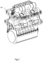
- the engine 100 is a large low-speed turbocharged two-stroke diesel engine. In some embodiments the engine is a two-stroke marine engine. In other embodiments the engine 100 can be another type and/or size of engine. In the example shown in the embodiment of Figure 1 , the engine 100 has six cylinders in line. Large low-speed turbocharged two-stroke diesel engines have typically between four and fourteen cylinders in line, carried by an engine frame. The engine 100 in some embodiments may be used in conjunction with another identical engine. The engine 100 may be used as the main engine, or one of the main engines, in an ocean-going vessel. The engine 100 may be coupled to the propeller shaft of the vessel. Alternatively the engine may be a stationary engine for operating a generator in a power station. The total output of the engine may, for example, range from 1,000 to 110,000 kW.
- the engine 100 has one or more fuel injector valves 102.
- the engine 100 as shown in Figure 1 has six fuel injector valves to correspond to the number of cylinders.
- the number of fuel injector valves will vary depending on the number of cylinders that are present in the engine 100.
- only one fuel injector valve 102 will be discussed with reference to the Figures.
- the fuel such as heavy fuel oil or diesel
- a slurry fuel In contrast to known fuel injectors, the fuel, such as heavy fuel oil or diesel, is replaced with a slurry fuel.
- the slurry fuel has different properties compared to heavy fuel oils or other oil-based hydrocarbon fuels.
- the slurry fuel can be a carbonaceous aqueous slurry fuel.
- the slurry fuel is a micronized refined carbon (MRC) fuel.
- the slurry fuel may be referred to as a coal and water mixture (CWM). That is a suspension of carbon particles, such as coal or solidified bitumen, in water.
- the fuel can be an emulsion of liquid particles of hydrocarbon, such as bitumen, and water.
- the slurry fuel comprises a solid fuel particulate component in a liquid solution, or a liquid fuel droplet component in a different liquid component.
- the carbonaceous aqueous slurry fuels can have a higher viscosity, have a non-Newtonian rheology and are more difficult to atomise.
- the solid carbon particles of the carbonaceous aqueous slurry fuels can have a tendency to deposit when the slurry fuel is not flowing.
- slurry fuel will incorporate a carbonaceous aqueous slurry fuel, other slurry fuels and emulsion fuels.
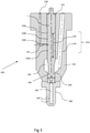
- FIG. 2 shows a schematic cross sectional representation of the fuel injector valve 102.
- the fuel injector valve 102 is elongate and extends along a longitudinal axis A-A.
- the fuel injector valve 102 has a first end 104 and a second end 106.
- the fuel injector valve 102 is generally tapered in cross section from the second end 106 to the first end 104.
- the fuel injector valve 102 is generally cylindrical or conical in shape.
- the fuel injector valve 102 comprises a housing 110 for mounting the fuel injector valve 102 to the engine or other suitable structure proximal to the engine 100.
- the housing 110 surrounds and protects the internal parts of the fuel injector valve 102.
- a nozzle 108 is mounted on the first end 104 of the fuel injector valve 102.
- the housing 110 is provided with a sealing liquid inlet port 112 and an actuation liquid inlet port 114.
- the actuation liquid is for actuating the fuel injector valve 102 and urging the slurry fuel in the fuel injector valve 102 into a combustion chamber 300 (see for example Figure 4 ) of the engine.
- the actuation liquid arrangement will be discussed in more detail below.
- the sealing liquid is for lubricating and separating the slurry fuel from other parts of the fuel injector valve 102.
- the sealing liquid in some embodiments is sealing oil.
- sealing liquid will be used herein after to refer to a liquid that seals and lubricates parts of the fuel injector valve 102.
- the sealing liquid arrangement will be discussed in more detail below.
- the actuation liquid is also used for the sealing liquid and this will be discussed in further detail below with respect to the actuation liquid.
- the housing 110 is provided with a fuel inlet port 116 for fluid communication with a first reservoir 118 of carbonaceous slurry fuel.
- the first reservoir 118 is a fuel tank which can be located remote from the fuel injector valve 102.
- the first reservoir 118 is in fluid communication with the fuel inlet port 116 by one or more fuel lines 130.
- the fuel inlet port 116 may connect to one or more sources of fuel, for example by means of a three-way valve 126, allowing the fuel injector valve 102 to switch between a primary source of fuel stored in the first reservoir 118 and a secondary source of fuel stored in a second reservoir 128.
- the second reservoir 128 is in fluid communication with the fuel inlet port 116 via the one or more fuel lines 130.
- the second reservoir 128 is also a fuel tank which can be located remote from the fuel injector valve 102.
- the primary and secondary sources of fuel may comprise different sources of fuel.
- the first reservoir 118 comprises a slurry fuel and the second reservoir 128 comprises a different fuel, such as a non-slurry fuel such as a low sulphur hydrocarbon fuel system where the sulphur content is less than 0.1%, for example marine diesel oil (MDO).
- a non-slurry fuel such as a low sulphur hydrocarbon fuel system where the sulphur content is less than 0.1%, for example marine diesel oil (MDO).
- MDO marine diesel oil
- Alternative fuels, such as a heavy fuel oil (HFO) fuel system can be used.
- the second reservoir 128 comprises the same type of fuel as the first reservoir 118.
- the fuel from the first and the second reservoir 118, 128 is pumped to the fuel inlet port 116 by one or more fuel pumps (not shown).
- the fuel pump pressurises the fuel in the first and second reservoirs 118, 128 and drives the fuel from the first and second reservoirs 118, 128 to the fuel injector valve 102.
- the different fuels may be pressurised at different pressures.
- the second fuel reservoir 128 is not necessary, but provides additional resilience to the fuel system in case the engine 100 is required to burn a different type of fuel with different characteristics.
- the engine 100 can be switched from burning a slurry fuel to another type of fuel to reduce emissions in certain geographical areas or to flush the slurry fuel from the fuel system.
- the fuel injector valve 102 may be operated using a fuel different from a slurry fuel prior to shut down of the engine 100 in order to flush the fuel injector valve 102.
- a fuel such as HDO or MDO, which do not contain carbonaceous solid particles, can be used to flush the fuel pipes and other parts of the fuel system free from carbonaceous particles.
- periodic maintenance of the fuel injector valve 102 can be carried out and deposition of particulates can be reduced and / or eliminated.
- the MRC fuel may not flow, and it can be difficult to remove from the injector channels by flushing.
- the fuel inlet port 116 connects to a pump chamber 120 in the valve housing 110 via a fuel supply valve 122.
- the fuel supply valve 122 will be discussed in further detail below.
- the pump chamber 120 is in fluid communication with the nozzle 108 via a nozzle fuel conduit 124.
- the nozzle fuel conduit 124 bypasses the fuel supply valve 122, so that fuel can flow from the pump chamber 120 to the nozzle 108 without passing through the fuel supply valve 122.
- the nozzle fuel conduit may extend to the nozzle 108 from the fuel supply valve 122, so that fuel can flow from the pump chamber 120 to the nozzle 108 via the fuel supply valve 122.
- the nozzle fuel conduit 124 extends longitudinally along the axis A-A.
- the nozzle fuel conduit 124 may comprise a plurality of nozzle fuel conduits 124 (not shown).
- a plurality of fuel nozzle conduits 124 is used to increase the flow rate of slurry fuel delivered to the nozzle 108.
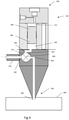
- Figure 3 shows a cross sectional side view of the tip of the fuel injector valve 102. As mentioned above, the nozzle 108 is mounted at the first end 104 of the housing 110 of the fuel injector valve 102.
- the nozzle 108 is a separate element that is mounted to the first end 104 of the housing 110. In other embodiments, the nozzle 108 is integral with the housing 110.
- the nozzle 108 has one or more fuel outlet holes 140.
- the fuel outlet hole may be axially aligned with the axis A-A.
- the nozzle 108 comprises a plurality of nozzle bores (not shown) that are radially and / or axially distributed over the nozzle 108.
- the housing 110 of the fuel injector valve 102 comprises a longitudinal bore 132.
- the longitudinal bore 132 extends from the first end 104 of the fuel injector valve 102 towards the second end 106.
- the longitudinal bore 132 is axially aligned with the axis A-A.
- a moveable valve needle 134 is mounted within the longitudinal bore 132.
- the moveable valve needle 134 is slidably received in the longitudinal bore 132.
- the moveable valve needle 134 is moveable between a closed position and an open position along the longitudinal axis A-A and a longitudinal axis of the moveable valve needle 134.
- the direction of movement of the moveable valve needle 134 is shown by the two-headed arrow in Figure 3.
- Figure 3 shows the moveable valve needle 134 in the open position.
- a ghosted representation of the moveable valve needle 134 in the closed position is shown by a dotted line in Figure 3 .
- a tip 136 of the moveable valve needle 134 abuts against a needle valve seat 138. That is, in the closed position, the valve needle 134 rests on the needle valve seat 138.
- the moveable valve needle 134 is biased towards the closed position by a spring 142 (shown in Figure 2 ).
- a needle fuel chamber 144 surrounds the tip 136 of the moveable valve needle 134.
- the needle fuel chamber 144 is in fluid communication with the nozzle fuel conduit 124.
- the needle fuel chamber 144 is in fluid communication with a longitudinal nozzle bore 146.
- the longitudinal nozzle bore 146 is axially aligned with the longitudinal axis A-A and the longitudinal bore 132. This means that the slurry fuel can flow from the needle fuel chamber 144 to the longitudinal bore 146 when the moveable valve needle 134 is in the open position.
- the moveable valve needle 134 is coupled to a needle piston 148.
- the spring 142 is mounted in a spring chamber 150 between the needle piston 148 and a spring shoulder portion 152.
- the spring 142 is a coil spring and urges the needle piston 148 and the moveable valve needle 134 toward the first end 104 and the closed position.
- the spring 142 can be other types of spring or any suitable means for urging the moveable valve needle 134 towards the closed position.
- a fuel injection piston 200 is provided in a first bore 202.
- the fuel injection piston 200 is substantially cylindrical and the first bore 202 is reciprocally shaped.
- the fuel injection piston 200 and the first bore 202 are axially aligned with axis A-A.
- the fuel injection piston 200 is moveable within the first bore 202.
- the fuel injection piston is axially slidable within the first bore 202.
- a lower surface 204 of fuel injection piston 200 is adjacent to and in contact with the slurry fuel in the pump chamber 120.
- the fuel injection piston 200 is arranged to move within the first bore 202 and urge the slurry fuel towards the nozzle 108 via the nozzle fuel conduit 124.
- the functionality of the fuel injection piston 200 will be discussed in more detail further below.
- the fuel injection piston 200 is coupled to an actuation piston 206 that is located within a second bore 208.
- the fuel injection piston 200 and actuation piston 206 as shown in Figure 2 are part of the same shuttle piston 205.
- the shuttle piston 205 is a single integral element that slidably moves within first and second bores 202, 208.
- the actuation piston 206 is provided in the second bore 208. In some embodiments the first bore 202 and the second bore 208 are the same. The actuation piston 206 and the second bore 208 are axially aligned with axis A-A. The actuation piston 206 is moveable within the second bore 208. The actuation piston 206 is axially slidable within the second bore 208. In some embodiments the actuation piston 206 and the fuel injection piston 200 are integral or mechanically coupled together. In other embodiments the actuation piston 206 can be remote from the fuel injection piston 200 such that the pistons 200, 206 are separate moveable elements.
- An upper surface 210 of the actuation piston 206 is adjacent to and in contact with an actuation liquid within an actuation chamber 212.
- the actuation liquid is part of a high pressure hydraulic system having an actuation liquid reservoir 216.
- the actuation chamber 212 is in fluid communication with the actuation liquid inlet port 114 via an actuation liquid supply conduit 214.
- the supply of the high pressure actuation liquid is controlled with an actuation control valve 218.
- the actuation control valve 218 selectively controls the flow of the actuation liquid to the actuation chamber 212.
- the reservoir 216 of the actuation liquid may be an existing source, such as a common rail system or a cam-shaft system, for providing actuation liquid of high pulsating pressure. In this way the actuation control valve 218 controls when the high pressure actuation liquid enters the actuation chamber 212 and urges the fuel injection piston 200 towards the first end 104.
- actuation liquid egresses from the actuation chamber 212 back to the actuation liquid reservoir 216 via a low pressure drain line (not shown). This means that the actuation liquid is recycled and reused for subsequent injection cycles.
- the actuation system can be any suitable means for exerting a force on the fuel injection piston 200.
- the actuation liquid is also the sealing liquid. This means that there is no sealing liquid reservoir 220 and the sealing liquid reservoir is also the actuation liquid reservoir 216.
- the sealing control valve 222 is coupled to the actuation liquid reservoir 216. This means that the sealing control valve 222 delivers actuation liquid to the sealing liquid inlet port 112.
- a conduit (not shown) is coupled to the sealing liquid inlet port 112 and is in fluid communication with a component of the actuation liquid system, such as the actuation liquid reservoir 216, the actuation liquid control valve 218 and / or the actuation liquid inlet port 114.
- a component of the actuation liquid system such as the actuation liquid reservoir 216, the actuation liquid control valve 218 and / or the actuation liquid inlet port 114.
- the functionality of the sealing liquid is the same as previously discussed, except that the sealing liquid is the actuation liquid.
- the fuel injection piston 200 is arranged to pressurise the slurry fuel in the pump chamber 120 by virtue of the high pressure actuation liquid exerting a high pressure or force on the actuation piston 206.
- the slurry fuel contains hard wearing particles which wear and damage the fuel injector valve 102. Accordingly a sealing arrangement is provided to seal the fuel system, which contains the slurry fuel, from other parts of the fuel injection. Sealing liquid is used to separate and isolate the slurry fuel as well as lubricate moving parts. The sealing liquid arrangement will be discussed in further detail with reference to Figures 2 and 3 .
- Coal-water slurry fuels typically contain no oil, whereby sealing and lubricating properties of coal-water slurry fuels are typically substandard or absent.
- a sealing liquid is provided for moving parts for lubrication purposes and for preventing migration of solid particles within the fuel injector valve 102.
- the sealing liquid can also prevent build-up of sludge and accumulation of carbonaceous particles in any deposits.
- the sealing liquid is supplied from a sealing oil reservoir 220 to the sealing liquid inlet port 112 via a sealing control valve 222.
- the sealing liquid inlet port 112 is in fluid communication with a groove 224 on the fuel injection piston 200 via sealing piston conduit 226.
- the groove 224 is located around the outer peripheral cylindrical surface of the fuel injection piston 200.
- the groove 224 is a circumferential groove.
- the sealing liquid fills a clearance between the first and / or second bores 202, 208 in the housing 110 and the fuel injection piston, or pump piston, 200 and/or the actuation piston 206. This seals the clearance between the pump chamber 120 and the actuation liquid chamber 212.
- the sealing liquid inlet port 112 is also in fluid communication with at least one circumferential groove 228 around the moveable valve needle 134 via a nozzle sealing liquid conduit 230.
- the sealing arrangement around the nozzle 108 will be discussed in further detail with respect to Figure 3 .
- the nozzle sealing liquid conduit 230 is in fluid communication with a sealing liquid nozzle outlet 232.
- the sealing liquid nozzle outlet 232 is in fluid communication with at least one circumferential groove 228 on the moveable valve needle 134.
- the sealing liquid migrates from the sealing liquid nozzle outlet 232 between the clearance of the outer surface of the movable valve needle 134 and the surface of the longitudinal bore 132.
- the circumferential grooves 228a, 228b, 228c, 228d may be rectangular or round faced turned into the moveable valve needle 134 on a face of the moveable valve needle 134 being in direct contact with, or directly facing, the longitudinal bore 132.
- the plurality of the circumferential grooves 228a, 228b, 228c, 228d is disposed in an intermediate portion 234 of the moveable valve needle 134.
- the intermediate portion 234 substantially coincides with the portion of the longitudinal bore 132 being closest to the needle fuel chamber 144.
- the circumferential grooves 228a, 228b, 228c, 228d are substantially equidistantly spaced over the intermediate portion 234.
- the arrangement of providing the circumferential grooves 228a, 228b, 228c, 228d with sealing liquid has the effect that the moveable valve needle 134 is maintained at a central coaxial position in respect of the valve seat 138, thus the provision of sealing liquid in the clearance between the face of the moveable valve needle 134 and the longitudinal bore 132 facilitates that this clearance is occupied by incompressible sealing liquid and hence preventing the moveable valve needle 134 from deviating from a position aligned with the longitudinal axis A-A.
- the pressure of the sealing liquid can be sufficient to promote a flow of sealing liquid into the needle fuel chamber 144.
- sealing liquid drains from the circumferential grooves 228a, 228b, 228c, 228d and on to the needle seat 138. This causes the sealing liquid to mix with the slurry fuel in the needle fuel chamber 144.
- the sealing liquid in some embodiments is a liquid hydrocarbon oil, such as diesel oil, that burns easier than the slurry fuel. Accordingly, sealing liquid draining into the fuel chamber 144 can promote the combustion of the slurry fuel in the combustion chamber 300.
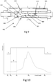
- Figure 7 discloses a partial cross section of the nozzle 108 of the fuel injector valve 102.
- an additional conduit 700 in fluid communication with the needle valve seat 138 and the nozzle sealing liquid conduit 230.
- the sealing liquid is added to the slurry fuel at the very last moment before the slurry fuel is injected into the combustion chamber 300.
- the sealing liquid has the minimum amount of time to negatively affect the slurry fuel.
- diesel oil can negatively affect and destabilise micronized refined carbon (MRC) slurry fuel.
- MRC micronized refined carbon
- the additional conduit 700 is in fluid communication with the needle fuel chamber 144.
- the connection between the additional conduit 700 and the needle fuel chamber 144 is not shown.
- the additional conduit 700 connects the nozzle sealing liquid conduit 230 to the needle fuel chamber 144.
- the nozzle sealing liquid conduit 230 provides sealing liquid to the needle valve seat 138 and / or the needle fuel chamber 144.
- one additional conduit 700 is shown in Figure 7 , in other embodiments a plurality of additional conduits 700 is provided for fluid communication between the nozzle sealing liquid conduit 230 and the needle valve seat 138, the needle fuel chamber 144, and / or any other part of the nozzle 108.
- the sealing liquid is typically a lighter hydrocarbon which burns more easily than the slurry fuel. This means that the sealing liquid can be used as a pilot fuel to improve the combustibility of the slurry fuel. In this way, the sealing liquid supplied by the source of sealing liquid 220 may be used to improve the lubricity and ignitability performance. As a result, the wear of the moveable valve needle 134 and the tip 136 abrading against the needle seat 138 due to shortage of the lubrication is limited.
- the rate of flow of the sealing liquid to the needle fuel chamber 144 and / or the needle valve seat 138 can be varied and controlled. This means that the amount of sealing liquid used as a pilot fuel can be adjusted depending on the characteristics of the slurry fuel.
- FIG. 4 is a schematic representation of the fuel injector valve 102.
- the sealing liquid and the corresponding valves and conduits have not been shown.
- the moveable valve needle 134 and the corresponding structural features in the nozzle 108 have also been omitted for clarity.
- the fuel supply valve 122 controls the flow of the slurry fuel into the fuel injector valve 102.
- the fuel supply valve 122 is mounted inside the fuel injector valve 102.
- the fuel supply valve 122 is mounted between the fuel reservoir 118 and the pump chamber 120.
- the fuel supply valve 122 is a one-way valve. This means that the slurry fuel can only flow into the fuel injector valve 102.
- the fuel supply valve 122 is a two way valve, but the fuel supply valve 122 is selectively controlled to open only when the pressure in the pump chamber 120 is less than the pressure of the slurry fuel in the fuel inlet port 116.
- the fuel supply valve 122 is in fluid communication between the fuel inlet port 116 and the pump chamber 120.
- the fuel inlet port 116 is arranged in the fuel supply valve 122.
- the fuel inlet port 116 is remote from the fuel supply valve 122.
- the slurry fuel is in some embodiments pressurised at a pressure of 1 bar to 20 bar. In other embodiments the slurry fuel is at a pressure of 6 bar to 15 bar. It is to be noted that there are three separate liquids that are supplied to the fuel injector valve 102. The sealing liquid, the actuation liquid, and the slurry fuel are all at different pressures. The different pressures may be provided to accommodate different functions of the sealing liquid, the actuation liquid and the slurry fuel.
- the fuel supply valve 122 comprises a supply valve fuel inlet 302 in fluid communication with the fuel reservoir 118 via the fuel inlet port 116.
- the supply valve fuel inlet 302 is arranged to let the slurry fuel flow into the fuel supply valve 122.
- the fuel supply valve 122 further comprises a supply valve fuel outlet 304 in fluid communication with the nozzle 108 of the fuel injector valve 102.
- the nozzle fuel conduit bypasses the fuel supply valve 122, so that fuel can flow from the pump chamber 120 to the nozzle 108 without passing through the fuel supply valve 122, and so the supply valve fuel outlet 304 may be omitted.
- the fuel supply valve 122 also comprises a pump chamber port 306 in fluid communication with the pump chamber 120 of the fuel injector valve 102.
- the fuel supply valve 122 comprise a supply valve moveable element 308 mounted within a valve chamber in a fuel supply valve housing 310.
- the supply valve moveable element 308 in some embodiments is a moveable valve gate 308.
- the moveable valve gate 308 may be selectively located to define one or more slurry fuel flow paths in the fuel supply valve 122.
- the valve gate 308 comprises a conduit with a moveable slurry fuel flow path.
- the valve gate 308 is a solid element which diverts the flow of the slurry fuel between a first slurry fuel path and a second slurry fuel path.
- the valve gate 308 is moveable in the valve chamber between a first position wherein the supply valve fuel inlet 302 is in fluid communication along a first slurry fuel flow path with the pump chamber port 306 and a second position wherein the supply valve fuel outlet 304 is in fluid communication along a second slurry fuel flow path with the pump chamber port 306.
- valve gate 308 selectively controls flow of the slurry fuel from the supply valve fuel inlet 302 to the pump chamber 120.
- the fuel supply valve 122 selectively controls whether the pump chamber 120 is connected to the fuel inlet port 116 or the nozzle 108 of the fuel injector valve 102. In the first position the fuel supply valve 122 is open with respect to the fuel inlet port 116 and allows the slurry fuel to flow into the pump chamber 120. In the second position the fuel supply valve 122 is closed with respect to the fuel inlet port 116 and the slurry fuel is not allowed to flow into the pump chamber 120.
- valve gate 308 In a first filling phase, the valve gate 308 is in the first position and the slurry fuel flows through the fuel supply valve 122 into the pump chamber 120. The pressure of the slurry fuel is sufficient to push the fuel injection piston 200 upwards towards the second end 106. As the fuel injection piston 200 and the actuation piston 206 are pushed upwards to the second end 106, a portion of the actuation liquid in the actuation chamber 212 flows back into the actuation liquid reservoir 216.
- a second valve cut-off phase the pump chamber 120 becomes full with the slurry fuel.
- the valve gate 308 of the fuel supply valve 122 moves from the first position to the second position.
- the fuel inlet port 116 is no longer in fluid communication with the pump chamber 120.
- the supply valve moveable element 308 moves between the first and second positions, the moveable element does not substantially exert a force opposing a flow of the slurry fuel into the pump chamber 120. This means that the slurry fuel can be maintained at a low pressure and the action of the fuel supply valve 122 opening and closing does not increase the pressure on the slurry fuel.
- the fuel supply valve 122 exerts minimal additional pressure on the slurry fuel and limits the chances of the non-Newtonian slurry fuel precipitating out or the solid fuel particles agglomerating. This avoids the fuel supply valve 122 causing misfires due to clogging of the slurry fuel in the fuel supply valve 122 or the pump chamber 120.
- the opposing force of the valve gate 308 against the flow of the slurry fuel is less than 170N. In further embodiments the opposing force of the valve gate 308 against the flow of the slurry fuel is less than 150N. In yet further embodiments the opposing force of the moveable element 308 against the flow of the slurry fuel is less than 100N. In yet further embodiments the opposing force of the valve gate 308 against the flow of the slurry fuel is less than 50N. In yet further embodiments the opposing force of the valve gate 308 against the flow of the slurry fuel is less than 25N. In yet further embodiments the opposing force of the valve gate 308 against the flow of the slurry fuel is less than 10N.
- the opposing force of the moveable element 308 against the flow of the slurry fuel is less than 5N. In yet further embodiments the opposing force of the valve gate 308 against the flow of the slurry fuel is approximately or equal to 0N.
- actuation liquid control valve 218 opens and high pressure actuation liquid rapidly flows into the actuation chamber 212. Since the actuation liquid is at a much greater pressure than the slurry fuel in the pump chamber 120, a force urges the fuel injection piston 200 rapidly towards the first end 104. This causes the slurry fuel to be pressurised and forced into the needle fuel chamber 144. In some embodiments this is the only time that the slurry fuel is exposed to a high pressure, to limit the chances of the slurry fuel precipitating or agglomerating. The pressure of the slurry fuel causes the needle piston 148 to recoil and move the moveable needle valve 134 into an open position. The slurry fuel is then pushed into the combustion chamber 300.
- a fourth valve open phase the spring 142 urges the needle piston 148 and the moveable valve needle 134 to the closed position.
- the valve gate 308 of the fuel supply valve 122 moves into the first position. The cycle then starts again with the first filling phase.
- the fuel supply valve is actuated with a motor and electronic control system. In other embodiments the fuel supply valve is actuated with a gearing system coupled and synced to the engine timing. In other embodiments the fuel supply valve is actuated with any suitable means for actuating and moving the valve gate 308.
- Figure 5 shows a perspective view with a partial cut-away of the fuel injector valve 500.
- the fuel injector valve 500 is similar to the fuel injector valve 102 as discussed with reference to previous embodiments.
- the fuel injector valve 500 comprises a different structure of the fuel supply valve 502, which will be discussed in further detail now.
- the fuel injector valve 500 comprises a moveable cartridge 504.
- the moveable cartridge 504 may be considered to comprise a valve gate.
- the moveable cartridge 504 in some embodiments is rotatable about the longitudinal axis B-B of the fuel injector valve 500.
- the rotatable cartridge 504 comprises a plurality of chambers 506 which are circumferentially distributed around the rotatable cartridge 504.
- Figure 5 shows three chambers 506 spaced around the axis B-B.
- the rotatable cartridge 504 is rotatably mountable on a bearing surface (not shown) within a reciprocal cartridge chamber 520.
- the cartridge chamber 520 allows free rotation of the rotatable cartridge 504 therein.
- the cartridge chamber 520 is defined by side walls 522 of the housing 110.
- An upper surface 524 of the cartridge chamber 520 is provided by an injector fuel valve cap 516.
- a lower surface 526 of the cartridge chamber 504 is defined by an intermediary wall 528.
- the bearing surfaces of the rotatable cartridge 504 are respectively located on the lower and upper surfaces 526, 524.
- Each chamber 506 comprises a longitudinal bore 508 which is substantially parallel with the axis B-B.
- the longitudinal bore 508 in some embodiments is an open bore such that slurry fuel is able to enter the bore from the underside and actuation liquid is able to enter the bore from above.
- a fuel injection piston 510 and an actuation piston 512 are provided in each longitudinal bore 508.
- the fuel injection piston 510 and actuation piston 512 are part of the same shuttle piston 518 and are slidably disposed in the longitudinal bore.
- the arrangement of each of the chambers 506 and the fuel injection piston 510 and the actuation piston 512 is the same as the fuel injection valve 102 discussed in respect of the previous embodiments. In this way the chambers 506 can be similarly considered to be a pump chamber 120 and an actuation chamber 212.
- a sealing liquid is provided to lubricate and seal the pump chamber 120 and the actuation chamber 212.
- one or more rotation cartridge sealing liquid conduits may be provided to seal and lubricate the rotatable chamber 504.
- the one or more rotation cartridge sealing liquid conduits are provided at the bearing surfaces on the lower and upper surfaces 526, 524. This means that the sealing liquid is provided around a lip of the periphery of each pump chamber 120 on the rotation cartridge 504 and prevents the slurry fuel from contaminating the rotation mechanism of the rotation cartridge.
- the actuation piston 512 is in fluid communication with the high pressure actuation reservoir 216 via actuation liquid port 514.
- the actuation liquid port 514 is located in an injector fuel valve cap 516.
- the injector fuel valve cap 516 is mountable on the housing 110. The functionality and arrangement of the actuation liquid is the same as previously discussed embodiments.
- the rotatable cartridge 504 rotates and sequentially positions each chamber 506 in a different relative position with respect to the actuation liquid port 514, the supply valve fuel inlet and the supply valve fuel outlet.
- the supply valve fuel inlet and the supply valve fuel outlet and their respective fluid connections through the fuel valve injector 500 are the same as the previously described fuel valve injector 102.
- the rotatable cartridge 504 In a first rotation position the rotatable cartridge 504 is positioned such that the pump chamber 120 is in fluid communication with the supply valve fuel inlet.
- the fuel inlet port 116 receives fuel from the fuel reservoir 118 and the fuel inlet port 116 is in fluid communication with the supply valve fuel inlet.
- the slurry fuel is maintained at a low pressure when the slurry fuel flows into the pump chamber 120 of a first chamber 506 of the rotation cartridge 504.
- the slurry fuel is kept at a pressure between 6 bar and 15 bar when the slurry fuel enters the fuel supply valve 502.
- a second rotation position the rotatable cartridge 504 rotates such that the pump chamber 120 of the first chamber 506 of the rotation cartridge 504 is aligned with the supply valve fuel outlet.
- the actuation chamber 212 is aligned with the actuation liquid port 514.
- the fuel injector valve is ready to fire and drive the slurry fuel in the pump chamber 120 to the nozzle 108.
- the arrangement of the nozzle 108 is the same as described with reference to the previous embodiments.
- the first chamber 506 of the rotation cartridge 504 is then rotated back to the first rotation position so that the pump chamber 120 is ready to be filled again.
- the rotation cartridge moves the first chamber 506 of the rotation cartridge 504 to a third rotation position.
- the rotatable cartridge is aligned with a flushing port (not shown).
- the flushing port is connected to a flushing medium system (not shown) that flushes the pump chamber 120 and the actuation chamber 212 in between the second position and the first position.
- the flushing medium system delivers a flushing liquid to the rotatable cartridge 504. In other words, the flushing stage occurs between the filling stage and the injection stage.
- the flushing system delivers flushing medium to both the top and bottom of the shuttle piston 518.
- the flushing liquid is provided firstly to the bottom of the shuttle piston 518 in the pump chamber 120, forcing the shuttle piston 518 to the top dead centre position.
- the remaining actuating liquid on or at the top of the chamber 506 is collected and sent to the actuating liquid reservoir 216.
- the collection of the actuation liquid is similar to the process as discussed with respect to the previous embodiments. Flushing medium is then pumped into the top chamber, forcing the piston to bottom dead centre and evacuating the flushing medium from the lower chamber.
- the rotation cartridge 504 as shown in Figure 5 comprises three chambers 506 with three respective rotation positions. However, there may be a greater number of rotation positions and chambers 506. This may for example be advantageous if the filling of the low pressure slurry into the pump chamber 120 is the slowest step of the injection process.
- the revolving cartridge 504 is rotated using hydraulic oil from a servo oil system (not shown) from the engine 100. In this way the timing of the rotatable cartridge 504 is driven by the speed of the engine 100.
- a hydraulic piston (not shown) connected to a spur gear (not shown) allows the rotating cartridge 504 to rotate about the axis B-B.
- a geared system (not shown) ensures that the chambers 506 line up with their respective filling and fuel egress ports in the first, second and third rotation positions. Additionally the geared system may ensure a good seal is maintained.
- the rotation of rotatable cartridge 504 ensures that the slurry fuel is selectively controlled in each chamber 506.
- the rotation of the rotatable cartridge 504 is substantially transverse to the direction of flow of the slurry fuel into the pump chamber.
- the rotation of the rotatable cartridge 504 rotates across the flow of the slurry fuel. This means that the force of rotating the rotatable cartridge 504 on the slurry fuel is minimal.
- the rotatable cartridge 504 is rotated with other means, for example a separate motor and electronic control system.
- the rotatable cartridge can be operated with any other suitable means for rotating the cartridge 504 between the different positions.
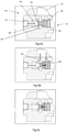
- Figures 6a to 6c are partial cross sectional side views of the fuel supply valve 122 of the fuel injection valve 102.
- Figures 6a to 6c are sequential steps of the fuel supply valve 122 moving between the first and second positions.
- the fuel injector valve 102 is the same as shown in Figure 2 , except for the form of the fuel supply valve 122 and the pump chamber 120.
- the fuel supply valve 122 is integral with the housing 110 of the fuel injector valve 102.
- the structure of the fuel supply valve 122 and the pump chamber 120 have been modified and this will now be discussed in further detail.
- the fuel supply valve 122 is in the second position in which the fuel inlet port 116 and the supply valve fuel inlet 302 are not in fluid communication with the pump chamber 120, and the supply valve fuel outlet 304 is in fluid communication with the nozzle 108.
- the moveable element 308 is seated in fuel supply valve seat 600 and this cuts off the fuel inlet port 116 (and, in some embodiments, the supply valve fuel outlet 304) from the pump chamber 120. That is, in some embodiments, the supply valve fuel outlet 304 is in fluid communication with the pump chamber 120 when the fuel supply valve 122 is in the second position, and in some other embodiments the supply valve fuel outlet 304 is out of fluid communication with the pump chamber 120 when the fuel supply valve 122 is in the second position.
- the moveable element 308 is arranged to generate minimal static and dynamic friction so that that slurry fuel can push the valve gate 308.
- the valve gate 308 comprises an inlet surface 602 and a chamber surface 604.
- the surface area of the inlet surface 602 is smaller than the surface area of the chamber surface 604. Accordingly the fuel supply valve 122 is a differential area valve.
- the slurry fuel enters the fuel supply valve 122 at the fuel inlet port 116.
- the pump chamber 120 is empty in Figure 6a . This means that the pressure of the fuel P fuel exerted on the inlet surface 602 is greater than the pressure P chamber exerted on the chamber surface 604 in the pump chamber 120. Accordingly, the pressure of the slurry fuel exerts a force in the direction of the arrow as shown in Figure 6a .
- the slurry fuel flows into the pump chamber 120 and also into a spool valve conduit 606.
- the spool valve conduit 606 houses a portion of the moveable element 308 and the chamber surface 604 and is in fluid communication with the pump chamber 120. Accordingly as the pump chamber 120 fills with the slurry fuel, the spool valve conduit 606 also fills with the slurry fuel.
- valve gate 308 causes the valve gate 308 to move from the first position to the second position as shown in Figure 6c .
- the inertia of the moving valve gate 308 ensures that the valve gate 308 seats in the fuel supply valve seat 600 and closes off the flow of the fuel slurry.
- a soft spring (not shown) can be provided to urge the moveable element towards the second position. The soft spring is configured to exert a low force on the gate 308 to return the gate to its original position as shown in Figures 6a and 6c .
- the pump chamber 120 is now full of slurry fuel and the supply valve fuel outlet 304 and the nozzle 108 are in fluid communication with the pump chamber 120. This means that the pump piston 200 can inject the slurry fuel to the nozzle 108 ready for combustion.
- FIG 8 shows a cross sectional schematic side view of a fuel injector valve according to another embodiment.
- the fuel injector valve 800 of Figure 8 is a slurry fuel injector valve, and incorporates a fuel supply valve 822 that is itself an embodiment of the present invention.
- a cross sectional schematic side view of the fuel supply valve 822 is shown in Figure 9 .
- An overview of the fuel injector valve 800 will be provided first, followed by more a detailed explanation of its component parts.
- the fuel injector valve 800 is similar to the fuel injector valve 102 of Figure 2 , and the discussion herein will focus primarily on differences between the two in the interest of brevity.
- the fuel injector valve 800 comprises a nozzle 808 via which slurry fuel exits the injector valve 800 towards a combustion chamber of an engine in use.
- the engine may be any of the types of engine discussed above, such as a marine engine.
- the fuel injector valve 800 also comprises a housing 810, a pump cavity 860 within the housing 810, and a fluid-actuatable pump element 805 that divides the pump cavity 860 into a pump chamber 820 and an actuation chamber 812.
- the pump chamber 820 is for receiving the slurry fuel from the fuel supply valve 822.
- the actuation chamber 812 is for receiving actuation liquid to act on the pump element 805 to pump the slurry fuel from the pump chamber 820 to the nozzle 808 in use.
- the fluid-actuatable pump element 805 in this embodiment is a shuttle piston 805, which is slidably movable in the pump cavity 860.
- Shuttle seal oil is delivered to a clearance between the shuttle piston 805 and a surface of the pump cavity 860 from a shuttle seal oil inlet 809 that opens into the pump cavity 860.
- the shuttle seal oil lubricates the shuttle piston 805 and helps to isolate the actuation chamber 812 from the pump chamber 820.
- the shuttle piston 805 comprises a pump piston 801 that is slidably mounted in the pump chamber 820 and arranged to exert a force on the slurry fuel in use, and an actuation piston 807 that is coupled to the pump piston 801 and arranged to transmit a force to the pump piston 801 in use.
- the axis along which the pump piston 801, and indeed the whole shuttle piston 805, moves is offset from a longitudinal axis of the injector 800.
- the fluid-actuatable pump element 805 may be other than a shuttle piston, and may not be slidibly movable in the pump cavity 860.
- the pump element 805 may be a diaphragm of a diaphragm pump.
- the pump element 805 may be other than fluid-actuatable, such as actuatable by a mechanical driver.
- the fuel injector valve 800 further comprises the fuel supply valve 822 for selectively placing the pump chamber 820 in fluid communication with a fuel inlet 802 of the fuel supply valve 822.
- the fuel supply valve 822 will now be described in more detail with continuing reference to Figure 8 .
- the fuel supply valve 822 comprises the fuel inlet 802, which is for fluid communication with a slurry fuel reservoir.
- the slurry fuel reservoir is not shown in Figure 8 , but by way of example any of the above described arrangements of slurry fuel reservoir(s) may be used.
- the fuel supply valve 822 also comprises a fuel outlet 804 for fluid communication with the nozzle 808 of the fuel injector valve 800.
- the fuel outlet 804 is in fluid communication with a needle fuel chamber 844 via one or plural nozzle fuel conduits 824. Since MRC has a relatively low calorific property, relatively more fuel is required to generate a certain amount of power.
- the provision of more than one nozzle fuel conduit 824 permits more MRC to reach the nozzle 808 and thus increase the energy-per-injection-cycle.
- the provision of more than one fuel injector valves 800 in an engine also can permit more MRC to reach the respective nozzles 808 of the fuel injector valves 800 and thus increase the energy per cycle of the engine.
- the arrangement of the needle fuel chamber 844 and the nozzle fuel conduit(s) 824 substantially corresponds to that of the fuel injector valve 102 of Figure 2 , and so will not be described in the interest of brevity.
- the fuel supply valve 822 also comprises a pump chamber port 806 for fluid communication with the pump chamber 820.
- the pump chamber port 806 is in permanent fluid communication with the pump chamber 820, but in other embodiments a valve may be provided to control fluid flow between the pump chamber port 806 and the pump chamber 820.
- the fuel injector valve 800 has an actuation liquid inlet 850 through which actuation liquid is received into the actuation chamber 812, thereby to act on the pump element 805 to pump the slurry fuel from the pump chamber 820 to the nozzle 808 in use.
- the fuel injector valve 800 also has an actuation liquid outlet 852 through which actuation liquid may be expelled from the fuel injector valve 800 as the volume of the actuation chamber 812 reduces on filling the pump chamber 820 with slurry fuel and movement of the pump element 805.
- the fuel injector valve 800 further has an actuation fluid conduit 854 that fluidly connects the actuation chamber 812 with a clearance between a longitudinal bore 832 and a valve needle 834 that sits within the longitudinal bore 832.
- the needle valve 834 is movable relative to the longitudinal bore 832 to control the flow of slurry fuel from the needle fuel chamber 144 and the nozzle 808 towards the combustion chamber of an engine in use.
- the fuel supply valve 822 comprises a valve gate 875 that is moveable between a first position, at which the fuel inlet 802 is in fluid communication along a first slurry fuel flow path with the pump chamber port 806, and a second position, at which the fuel outlet 804 is in fluid communication along a second slurry fuel flow path with the pump chamber port 806.
- the fuel supply valve 822 comprises a valve seat 803 at the fuel inlet 802, and the valve gate 875 is a valve head 875 for cooperation with the valve seat 803.
- the fuel supply valve 822, and particularly the valve gate 875 could take a different form to that described here.
- the valve gate 875 is mounted for movement relative to the valve seat 803 between the first position, as shown in Figure 8 , and the second position.
- the movement is linear movement.
- the movement is sliding movement.
- the fuel supply valve 822 of this embodiment has a valve body 870 that comprises the valve gate 875 and is slidably movable in a valve bore 880 of the fuel supply valve 822.
- the valve body 870 is free to move in the valve bore 880.
- the fuel supply valve 822 may therefore be considered a fluid-actuatable poppet valve.
- the fuel supply valve 822 may be other than a poppet valve, and/or the movement of the valve gate could be other than linear movement or other than sliding movement, such as a rotational movement or a combination of rotational and translational movement, for example a pivoting or camming movement.
- valve gate 875 In the first position, the valve gate 875 is spaced from the valve seat 803 to permit slurry fuel to flow from the fuel inlet 802 to the pump chamber port 806 and towards the pump chamber 820.
- the valve gate 875 abuts against the valve seat 803 to hinder or prevent slurry fuel flowing from the fuel inlet 802 to the pump chamber port 806 and towards the pump chamber 820. That is, the fuel inlet 802 is, or is substantially, out of fluid communication with the pump chamber port 806 and the pump chamber 820, when the valve gate 875 is at the second position.
- the fuel supply valve 822 is thus for controlling the flow of slurry fuel into the fuel supply valve 822 and the fuel injector valve 800 as a whole.
- the pump chamber port 806 is in fluid communication with the fuel outlet 804 when the valve gate 875 is at the first position and when the valve gate 875 is at the second position.
- a valve may be configured to selectively block the fuel outlet 804.
- the valve gate 875 may block the fuel outlet 804 when at the first position.
- the valve gate 875 of the fuel supply valve 822 is fluid-actuatable. More specifically, the valve gate 875 is operable with a valve actuation liquid from an engine.
- the engine may be that into which the fuel injector valve 800 is to be installed to inject slurry fuel into a combustion chamber thereof.
- the fuel supply valve 822 comprises a valve actuation liquid chamber 872, into which valve actuation liquid is receivable to exert a force on the valve gate 875 to drive the valve gate 875 between the first position and the second position. More specifically, the valve actuation chamber 872 is on an opposite side of the valve gate 875 from the valve seat 803. Accordingly, feeding the valve actuation liquid into the valve actuation chamber 872 causes movement of the valve gate 875 towards the second position.
- the valve actuation liquid may be an oil, such as servo oil.
- valve actuation liquid chamber 872 is isolated from the pump chamber port 806. More specifically, the valve gate 875 itself blocks a flow path between the valve actuation liquid chamber 872 and the pump chamber port 806. This helps avoid the slurry fuel being contaminated with the valve actuation liquid, and helps avoid the slurry fuel contaminating the valve actuation liquid and degrading the fuel supply valve 822.
- the valve body 870 has one or more grooves 871 therein for receiving the valve actuation liquid between the valve body 870 and the valve bore 880 to lubricate movement of the valve body 870 in the valve bore 880 and to further help seal the slurry fuel from the valve actuation liquid.
- the groove(s) 871 are in fluid communication with the valve actuation chamber 872, so that the valve actuation liquid is able to flow into the groove(s) 871 from the valve actuation chamber 872.
- the one or more grooves 871 may be circumferential grooves that extend fully around a circumference of the valve body 870.
- the fuel supply valve 822 comprises a control valve 892 for controlling input of valve actuation liquid into the valve actuation chamber 872. More specifically, the fuel supply valve 822 comprises a valve actuation liquid conduit 890 via which valve actuation liquid is flowable into and out of the valve actuation chamber 872, and the control valve 892 is for controlling flow of valve actuation liquid through the valve actuation liquid conduit 890. In other embodiments, the valve actuation liquid may be flowable out of the valve actuation chamber 872 by a route other than the valve actuation liquid conduit 890, which may be controlled by the control valve 892 or another valve.
- the control valve 892 has a first port for fluid communication with the valve actuation liquid chamber 872, a second port for fluid communication with a source 894 of valve actuation liquid, and a third port for fluid communication with a drain 896, and the control valve 892 is for selecting which of the second and third ports is in fluid communication with the first port.
- the source 894 of valve actuation liquid may be a servo oil system of an engine, such as that into which the fuel injector valve 800 is to be installed.
- the control valve 892 could have a different number of ports. For example, in some embodiments, there may be a combined source 894 and drain 896, so that the third port could be omitted.
- control valve 892 is electrically or electronically controllable, such as by an engine control unit (ECU).
- ECU engine control unit
- other forms of control may be employed.
- Figure 10 shows a graph of pressure of the slurry fuel in the pump chamber 820 versus a crank angle of an engine (in which the fuel injector valve 800 is installed in use) during one engine cycle.
- Figure 10 also shows the position of the valve gate 875 at different times during the engine cycle.
- the control valve 892 is controlled in dependence on the crank angle of the engine, so as to ensure that the valve gate 875 is suitably positioned at different times in the engine cycle.
- slurry fuel flows through the fuel supply valve 822 from the fuel inlet 802 to the pump chamber port 806 and towards the pump chamber 820.
- the pressure of the slurry fuel albeit relatively low, is sufficient to push the fuel pump piston 801 to expand the pump chamber 820.
- the pressure of the slurry fuel may, for example, be less than 30 bar or optionally between 20 and 30 bar.
- valve actuation liquid is driven into the valve actuation chamber 872 via the valve actuation liquid conduit 890 under the control of the control valve 892.
- the valve actuation liquid in the valve actuation chamber 872 is preferably at higher pressure than the slurry fuel in the fuel inlet 802.
- the valve actuation liquid may be at a pressure of over 100 bar, such as between 180 and 200 bar.
- valve gate 875 Once the valve gate 875 is at the second position, high pressure actuation liquid is caused (such as by the engine control unit) to rapidly flow into the actuation chamber 812 via the actuation liquid inlet 850. Since the actuation liquid is at a much greater pressure than the slurry fuel in the pump chamber 820, the actuation liquid exerts a force on the pump element 805 to cause the slurry fuel in the pump chamber 820 to be pressurised, as shown in the graph of Figure 10 , and forced into the needle fuel chamber 844 via the nozzle fuel conduit 824. This causes the moveable valve needle 834 to move to an open position to permit the slurry fuel to be pushed out of the fuel injector valve 800 and towards the engine combustion chamber.
- actuation liquid is driven along the actuation fluid conduit 854 to the clearance between the longitudinal bore 832 and the valve needle 834 located therein, so as to help dislodge or flush carbonaceous or other hard-wearing particles that might have accumulated in the clearance.
- valve gate 875 Since the valve gate 875 is at the second position during this actuation of the injector, slurry fuel is unable to be forced also into the fuel inlet 802 from the pump chamber 820. To better ensure this, there may be a predetermined delay (shown as T in Figure 10 ), such as at least 50ms or at least 100 ms, between the valve gate 875 reaching the second position at crank angle A 2 of the engine and the high pressure actuation liquid being caused to rapidly flow into the actuation chamber 812 at a subsequent crank angle A 3 of the engine.
- T in Figure 10 a predetermined delay
- the timing of this actuation of the injector 800 may be such that the slurry fuel in the pump chamber 820 experiences a peak pressure when the piston in the engine combustion chamber is approximately at top dead centre (TDC) (crank angle A 4 of the engine, in Figure 10 ). However, in some embodiments, there may be a small timing offset between TDC and the peak pressure.
- the injection of the slurry fuel into the combustion chamber may lead or lag TDC.
- the timing offset is selectable or modifiable, such as by the engine control unit or by an operator suitably operating the engine control unit.
- the flow of high pressure actuation liquid into the actuation chamber 812 is caused to cease (such as by the engine control unit), and as a result the needle valve 834 moves to a closed position under the biasing force of a spring 842, as previously described with reference to other embodiments, to prevent or hinder the flow of slurry fuel from the needle fuel chamber 844 out of the fuel injector valve 800.
- valve actuation liquid into the valve actuation chamber 872 is caused to cease through operation of the control valve 892, such as by the engine control unit.
- the relatively low pressure of the slurry fuel in the fuel inlet 802 is then sufficient to drive the valve gate 875 from the second position to the first position at a crank angle A 5 of the engine, so as to open the fuel inlet 802 and begin cycle again.
- the valve gate 875 at least a portion of the valve actuation liquid is expelled from the valve actuation chamber 872 to the drain 896 via the valve actuation liquid conduit 890 and the control valve 892.
- the slurry fuel does not experience significant resistance to the valve gate 875 moving to the first portion.
- the drain 896 may return the valve actuation liquid back to the source 894 of valve actuation liquid.
- valve gate 875 there is no spring or other biasing device to urge the valve gate 875 towards the first position.
- biasing device may be present in other embodiments.
- the valve gate 875 during movement of the valve gate 875 from the first position to the second position, the valve gate 875 does not substantially exert a force opposing the flow of the slurry fuel from the fuel inlet 802. As described previously in relation to another embodiment, this means that the slurry fuel can be maintained at a relative low pressure, and so the chances of the non-Newtonian slurry fuel precipitating out or the solid fuel particles agglomerating are lessened. However, in other embodiments, during movement of the valve gate 875 from the first position to the second position, the valve gate 875 does exert a force opposing the flow of the slurry fuel from the fuel inlet 802.
Landscapes
- Engineering & Computer Science (AREA)
- Chemical & Material Sciences (AREA)
- Combustion & Propulsion (AREA)
- Mechanical Engineering (AREA)
- General Engineering & Computer Science (AREA)
- Oil, Petroleum & Natural Gas (AREA)
- Physics & Mathematics (AREA)
- Fluid Mechanics (AREA)
- Mining & Mineral Resources (AREA)
- Electromagnetism (AREA)
- Fuel-Injection Apparatus (AREA)
Claims (13)
- Kraftstoffzufuhrventil (822) für ein Schlammeinspritzventil (800), wobei das Kraftstoffzufuhrventil (822) Folgendes umfasst:einen Kraftstoffeinlass (802) zur Fluidverbindung mit einem Schlammkraftstoffreservoir;einen Kraftstoffauslass (804) zur Fluidverbindung mit einer Düse (808) des Kraftstoffeinspritzventils (800);eine Pumpenkammeröffnung (806) zur Fluidverbindung mit einer Pumpenkammer (820) des Kraftstoffeinspritzventils (800); undeinen Ventilschieber (875), der zwischen einer ersten Position, in der der Kraftstoffeinlass (802) entlang eines ersten Schlammkraftstoffflussweges mit der Pumpenkammeröffnung (806) in Fluidverbindung steht, und einer zweiten Position, in der der Kraftstoffauslass (804) entlang eines zweiten Schlammkraftstoffflussweges mit der Pumpenkammeröffnung (806) in Fluidverbindung steht, bewegbar ist;wobei der Ventilschieber (875) mit einer Ventilbetätigungsflüssigkeit von einem Motor (100) betätigt werden kann;dadurch gekennzeichnet, dassdas Kraftstoffzufuhrventil (822) eine Ventilbetätigungsflüssigkeitskammer (872) umfasst, wobei Ventilbetätigungsflüssigkeit in die Ventilbetätigungsflüssigkeitskammer (872) aufgenommen werden kann, um eine Kraft auf den Ventilschieber (875) auszuüben, um den Ventilschieber (875) zwischen der ersten und der zweiten Position zu bewegen, und wobei die Ventilbetätigungsflüssigkeitskammer (872) von der Pumpenkammeröffnung (806) isoliert ist.
- Kraftstoffzufuhrventil (822) nach Anspruch 1, wobei Ventilbetätigungsflüssigkeit in die Ventilbetätigungsflüssigkeitskammer (872) aufgenommen werden kann, um eine Kraft auf den Ventilschieber (875) auszuüben, um den Ventilschieber (875) in Richtung der zweiten Position zu bewegen.
- Kraftstoffzufuhrventil (822) nach Anspruch 1 oder Anspruch 2, umfassend einen Ventilkörper (870) und eine Ventilbohrung (880), wobei der Ventilkörper (870) den Ventilschieber (875) beinhaltet und in der Ventilbohrung (880) bewegbar ist, und wobei der Ventilkörper (870) mindestens eine Nut (871) darin zur Aufnahme der Ventilbetätigungsflüssigkeit zwischen dem Ventilkörper (870) und der Ventilbohrung (880) aufweist, um die Bewegung des Ventilkörpers (870) in der Ventilbohrung (870) zu schmieren.
- Kraftstoffzufuhrventil (822) nach einem der Ansprüche 1 bis 3, umfassend ein Steuerventil (892) zur Steuerung der Zufuhr von Ventilbetätigungsflüssigkeit in die Ventilbetätigungsflüssigkeitskammer (872).
- Kraftstoffzufuhrventil (822) nach Anspruch 4, wobei das Steuerventil (892) elektrisch oder elektronisch steuerbar ist.
- Kraftstoffzufuhrventil (822) nach Anspruch 4 oder Anspruch 5, wobei das Steuerventil (892) eine erste Öffnung zur Fluidverbindung mit der Ventilbetätigungsflüssigkeitskammer (872), eine zweite Öffnung zur Fluidverbindung mit einer Quelle (894) von Ventilbetätigungsflüssigkeit und eine dritte Öffnung zur Fluidverbindung mit einem Abfluss (896) aufweist, und
wobei das Steuerventil (892) dazu dient, auszuwählen, welche von der zweiten und dritten Öffnung in Fluidverbindung mit der ersten Öffnung steht. - Kraftstoffzufuhrventil (822) nach einem der Ansprüche 1 bis 6, wobei der Ventilschieber (875) linear zwischen der ersten und der zweiten Position bewegbar ist.
- Kraftstoffzufuhrventil (822) nach einem der Ansprüche 1 bis 7, wobei der Ventilschieber (875) es ermöglicht, dass Schlammkraftstoff von dem Kraftstoffeinlass (802) zu der Pumpenkammeröffnung (806) fließt, wenn sich der Ventilschieber (875) in der ersten Position befindet, und wobei der Ventilschieber (875) es behindert oder verhindert, dass Schlammkraftstoff von dem Kraftstoffeinlass (802) zu der Pumpenkammeröffnung (806) fließt, wenn sich der Ventilschieber (875) in der zweiten Position befindet.
- Kraftstoffzufuhrventil (822) nach einem der Ansprüche 1 bis 8, wobei die Pumpenkammeröffnung (806) in Fluidverbindung mit dem Kraftstoffauslass (804) steht, wenn sich der Ventilschieber (875) in der ersten Position befindet und wenn sich der Ventilschieber (875) in der zweiten Position befindet.
- Kraftstoffeinspritzventil (800) für einen Schlammkraftstoff, wobei das Kraftstoffeinspritzventil (800) folgendes umfasst:eine Düse (808), über die der Schlammkraftstoff aus dem Einspritzventil (800) in Richtung einer Brennkammer eines Motors austreten kann;ein Gehäuse (810) und einen Pumpenhohlraum (860) innerhalb des Gehäuses (810);ein Pumpenelement (805), das den Pumpenhohlraum (860) in eine Pumpenkammer (820) und eine Betätigungskammer (812) unterteilt; undein Kraftstoffzufuhrventil (822) nach einem der Ansprüche 1 bis 9 zum selektiven Anordnen der Pumpenkammer (820) in Fluidverbindung mit dem Kraftstoffeinlass (802) des Kraftstoffzufuhrventils (822).
- Kraftstoffeinspritzventil (800) nach Anspruch 10, wobei das Pumpenelement (805) fluidbetätigbar ist.
- Kraftstoffeinspritzventil (800) nach Anspruch 10 oder Anspruch 11, wobei das Pumpenelement (805) einen Pendelkolben (805) umfasst.
- Kraftstoffeinspritzventil (800) nach Anspruch 12, wobei der Pendelkolben (805) umfasst:einen Pumpenkolben (801), der gleitend in der Pumpenkammer (820) montiert und angeordnet ist, um eine Kraft auf den Schlammkraftstoff auszuüben; undeinen Betätigungskolben (807), der mit dem Pumpenkolben (801) gekoppelt und angeordnet ist, um eine Kraft auf den Pumpenkolben (801) zu übertragen.
Applications Claiming Priority (3)
| Application Number | Priority Date | Filing Date | Title |
|---|---|---|---|
| GB1703938.9A GB2560513A (en) | 2017-03-13 | 2017-03-13 | Fuel injection system |
| GBGB1719716.1A GB201719716D0 (en) | 2017-03-13 | 2017-11-28 | Fuel supply valve for a slurry fuel injector valve |
| PCT/EP2018/056278 WO2018167085A1 (en) | 2017-03-13 | 2018-03-13 | Fuel supply valve for a slurry fuel injector valve |
Publications (2)
| Publication Number | Publication Date |
|---|---|
| EP3596331A1 EP3596331A1 (de) | 2020-01-22 |
| EP3596331B1 true EP3596331B1 (de) | 2022-02-23 |
Family
ID=58605312
Family Applications (4)
| Application Number | Title | Priority Date | Filing Date |
|---|---|---|---|
| EP18714979.4A Active EP3596331B1 (de) | 2017-03-13 | 2018-03-13 | Kraftstoffzufuhrventil für ein schlammeinspritzventil |
| EP18714981.0A Active EP3596333B1 (de) | 2017-03-13 | 2018-03-13 | Ventilnadel |
| EP18714978.6A Withdrawn EP3596330A1 (de) | 2017-03-13 | 2018-03-13 | Kraftstoffeinspritzsystem |
| EP18714980.2A Active EP3596332B1 (de) | 2017-03-13 | 2018-03-13 | Kraftstoffeinspritzventil |
Family Applications After (3)
| Application Number | Title | Priority Date | Filing Date |
|---|---|---|---|
| EP18714981.0A Active EP3596333B1 (de) | 2017-03-13 | 2018-03-13 | Ventilnadel |
| EP18714978.6A Withdrawn EP3596330A1 (de) | 2017-03-13 | 2018-03-13 | Kraftstoffeinspritzsystem |
| EP18714980.2A Active EP3596332B1 (de) | 2017-03-13 | 2018-03-13 | Kraftstoffeinspritzventil |
Country Status (8)
| Country | Link |
|---|---|
| US (4) | US10890150B2 (de) |
| EP (4) | EP3596331B1 (de) |
| JP (4) | JP7117315B2 (de) |
| KR (4) | KR102513341B1 (de) |
| CN (4) | CN110573722B (de) |
| DK (3) | DK3596332T3 (de) |
| GB (4) | GB2560513A (de) |
| WO (4) | WO2018167083A1 (de) |
Families Citing this family (10)
| Publication number | Priority date | Publication date | Assignee | Title |
|---|---|---|---|---|
| CN109891084B (zh) * | 2016-08-29 | 2021-08-17 | 联邦科学与工业研究组织 | 用于使用浆料或乳化燃料的柴油发动机的改进喷射器装置 |
| GB2560513A (en) | 2017-03-13 | 2018-09-19 | Ap Moeller Maersk As | Fuel injection system |
| US10544771B2 (en) * | 2017-06-14 | 2020-01-28 | Caterpillar Inc. | Fuel injector body with counterbore insert |
| CN113153598B (zh) * | 2020-01-23 | 2025-11-11 | 罗伯特·博世有限公司 | 包括旋转针的燃料喷射器 |
| DE102020116707A1 (de) * | 2020-06-25 | 2021-12-30 | Man Energy Solutions Se | Kraftstoffinjektor einer Dual-Fuel Brennkraftmaschine und Dual-Fuel Brennkraftmaschine |
| DE102020127782A1 (de) * | 2020-10-22 | 2022-04-28 | Man Energy Solutions Se | Kraftstoffinjektor einer Dual-Fuel Brennkraftmaschine, Dual-Fuel Brennkraftmaschine und Verfahren zu Betreiben derselben |
| DK181318B1 (en) * | 2022-02-18 | 2023-08-10 | Man Energy Solutions Filial Af Man Energy Solutions Se Tyskland | A fuel valve for a large turbocharged two-stroke uniflow crosshead internal combustion engine |
| DK181865B1 (en) * | 2023-07-28 | 2025-02-25 | Man Energy Solutions Filial Af Man Energy Solutions Se Tyskland | A fuel valve for a large turbocharged two-stroke uniflow crosshead internal combustion engine |
| US12018624B1 (en) * | 2023-11-08 | 2024-06-25 | Patrick Hinchy | Camless engines |
| NL2037202B1 (en) | 2024-03-08 | 2025-09-22 | Canon Production Printing Holding Bv | Method of inkjet printing a multi-material structure |
Family Cites Families (64)
| Publication number | Priority date | Publication date | Assignee | Title |
|---|---|---|---|---|
| FR473174A (fr) | 1913-06-11 | 1915-01-05 | George William Heimrod | Redresseur de courant à vapeur de mercure |
| US2110365A (en) * | 1936-02-22 | 1938-03-08 | Saurer Ag Adolph | Injection nozzle for internal combustion engines |
| GB868093A (en) * | 1957-07-05 | 1961-05-17 | Maschf Augsburg Nuernberg Ag | Injection nozzle, especially for internal combustion engines |
| US3398936A (en) * | 1966-08-02 | 1968-08-27 | Curtiss Wright Corp | Fuel injection pintle |
| US3591086A (en) | 1968-05-31 | 1971-07-06 | Marquardt Corp | Nozzle for injection of slurry fuels |
| US3950147A (en) | 1974-08-08 | 1976-04-13 | Kamyr, Inc. | Process for feeding coal to a fluidized bed or suspended particle pressurized processing chamber and apparatus for carrying out the same |
| US4219154A (en) | 1978-07-10 | 1980-08-26 | The Bendix Corporation | Electronically controlled, solenoid operated fuel injection system |
| ZA813854B (en) | 1980-07-18 | 1982-07-28 | Lucas Industries Ltd | Fuel injection nozzles |
| US4408718A (en) * | 1981-09-25 | 1983-10-11 | General Motors Corporation | Electromagnetic unit fuel injector |
| JPS5951156A (ja) * | 1982-09-20 | 1984-03-24 | Nissan Motor Co Ltd | 内燃機関の燃料噴射装置 |
| DE3330774A1 (de) * | 1983-08-26 | 1985-03-14 | Robert Bosch Gmbh, 7000 Stuttgart | Kraftstoffeinspritzeinrichtung mit vor- und haupteinspritzung bei brennkraftmaschinen |
| JPS6056118A (ja) | 1983-09-05 | 1985-04-01 | Toyota Central Res & Dev Lab Inc | 圧縮着火式直接噴射内燃機関 |
| DE3505229A1 (de) * | 1985-02-05 | 1986-08-07 | Gebrüder Sulzer AG, Winterthur | Vorrichtung zum einspritzen von in einer fluessigkeit aufgeschwemmten, feinteiligem, festem brennstoff in den brennraum einer hubkolbenbrennkraftmaschine |
| US4681073A (en) | 1986-02-05 | 1987-07-21 | Deere & Company | Fuel injection control valve |
| US4782794A (en) * | 1986-08-18 | 1988-11-08 | General Electric Company | Fuel injector system |
| JPH063160Y2 (ja) * | 1987-04-21 | 1994-01-26 | 株式会社小松製作所 | デイ−ゼルエンジンの燃料噴射装置 |
| CA1308976C (en) * | 1987-08-25 | 1992-10-20 | Bertrand Dahung Hsu | Fuel injector system |
| US4862837A (en) | 1988-04-21 | 1989-09-05 | Defense Research Technologies, Inc. | Fuel injection of coal slurry using vortex nozzles and valves |
| CH678216A5 (de) | 1988-08-10 | 1991-08-15 | Sulzer Ag | |
| JPH0311264A (ja) | 1989-06-08 | 1991-01-18 | Nepon Kk | 温風暖房機の缶体腐食防止方法 |
| US5061513A (en) * | 1990-03-30 | 1991-10-29 | Flynn Paul L | Process for depositing hard coating in a nozzle orifice |
| US5056469A (en) * | 1990-06-29 | 1991-10-15 | Ail Corporation | Fuel injection system |
| US5193575A (en) | 1992-03-13 | 1993-03-16 | Dresser-Rand | Adjustable differential pressure valve |
| US5282570A (en) | 1992-05-12 | 1994-02-01 | General Electric Company | Electronically controlled accumulator injector |
| JPH06147057A (ja) | 1992-11-12 | 1994-05-27 | Nissan Motor Co Ltd | 燃料噴射ノズル |
| CN2173311Y (zh) | 1993-08-03 | 1994-08-03 | 刘茂本 | 液体喷射雾化喷嘴 |
| JPH07103106A (ja) * | 1993-09-30 | 1995-04-18 | Hino Motors Ltd | 燃料噴射装置 |
| AUPO501897A0 (en) * | 1997-02-10 | 1997-03-06 | Invent Engineering P/L | Hydraulically actuated electronic fuel injection system |
| DE19709795A1 (de) * | 1997-03-10 | 1998-09-17 | Bosch Gmbh Robert | Kraftstoffeinspritzventil für Brennkraftmaschinen |
| JPH10311264A (ja) * | 1997-05-10 | 1998-11-24 | Unisia Jecs Corp | フューエルインジェクタ |
| GB9810208D0 (en) | 1998-05-13 | 1998-07-08 | Lucas Ind Plc | Fuel injector |
| JP4445072B2 (ja) * | 1998-10-20 | 2010-04-07 | ヴェルトジィレ シュヴァイツ アクチェンゲゼルシャフト | ディーゼルエンジンのシリンダへの液体噴射装置及びディーゼルエンジン |
| US6237857B1 (en) * | 1999-08-11 | 2001-05-29 | Caterpillar Inc. | Three-way actuation control of a hydraulically actuated fuel injector |
| DE10022421A1 (de) | 2000-05-09 | 2001-11-15 | Bosch Gmbh Robert | Voreinspritzventil für die Steuerung des Kraftstoffzuflusses eines Kraftstoffeinspritzventils |
| JP2002227741A (ja) | 2001-02-02 | 2002-08-14 | Toyota Industries Corp | 燃料噴射装置 |
| EP1392967B1 (de) * | 2001-05-17 | 2007-04-04 | Robert Bosch Gmbh | Kraftstoffeinspritzeinrichtung |
| DE10218904A1 (de) * | 2001-05-17 | 2002-12-05 | Bosch Gmbh Robert | Kraftstoffeinspritzeinrichtung |
| DE10145822B4 (de) | 2001-09-17 | 2004-08-19 | Robert Bosch Gmbh | Injektor einer Kraftstoffeinspritzeinrichtung |
| US6662783B2 (en) * | 2001-10-22 | 2003-12-16 | Siemens Diesel Systems Technology | Digital valve |
| DE10158659A1 (de) | 2001-11-30 | 2003-06-12 | Bosch Gmbh Robert | Kraftstoffeinspritzeinrichtung für eine Brennkraftmaschine |
| US7320310B2 (en) * | 2003-04-02 | 2008-01-22 | Robert Bosch Gmbh | Fuel injector provided with provided with a pressure transmitter controlled by a servo valve |
| DE102004011282A1 (de) * | 2004-03-09 | 2005-09-29 | Robert Bosch Gmbh | Kraftstoffeinspritzeinrichtung für eine Brennkraftmaschine |
| JP3994990B2 (ja) * | 2004-07-21 | 2007-10-24 | 株式会社豊田中央研究所 | 燃料噴射装置 |
| JP3989495B2 (ja) * | 2004-09-22 | 2007-10-10 | トヨタ自動車株式会社 | 燃料噴射装置 |
| JP2007016741A (ja) * | 2005-07-11 | 2007-01-25 | Denso Corp | 燃料噴射弁 |
| JP4415962B2 (ja) * | 2006-03-17 | 2010-02-17 | 株式会社デンソー | インジェクタ |
| EP1837515A1 (de) | 2006-03-20 | 2007-09-26 | Delphi Technologies, Inc. | Dämpfungsanordnung für ein Einspritzventil |
| US7281500B1 (en) | 2006-08-21 | 2007-10-16 | Joseph Carl Firey | Supplementary slurry fuel atomizer and supply system |
| US20080047527A1 (en) | 2006-08-25 | 2008-02-28 | Jinhui Sun | Intensified common rail fuel injection system and method of operating an engine using same |
| JP2008057458A (ja) * | 2006-08-31 | 2008-03-13 | Mitsubishi Heavy Ind Ltd | 燃料噴射弁 |
| FI122557B (fi) | 2009-04-02 | 2012-03-30 | Waertsilae Finland Oy | Mäntämoottorin polttoaineenruiskutusjärjestely |
| WO2011125201A1 (ja) * | 2010-04-08 | 2011-10-13 | トヨタ自動車株式会社 | 燃料噴射弁 |
| SE534977C2 (sv) * | 2010-06-22 | 2012-03-06 | Scania Cv Ab | Insprutningsenhet för insprutning av ett första bränsle och ett andra bränsle i ett förbränningsutrymme |
| WO2012086006A1 (ja) | 2010-12-20 | 2012-06-28 | トヨタ自動車株式会社 | 燃料噴射弁 |
| JP6067973B2 (ja) * | 2012-02-28 | 2017-01-25 | ユニ・チャーム株式会社 | 創傷部被覆材 |
| CN102828875A (zh) * | 2012-09-28 | 2012-12-19 | 重庆大学 | 柴油机用油水瞬时乳化喷油器 |
| US20140314603A1 (en) * | 2013-04-23 | 2014-10-23 | Hitachi. Ltd | Fuel pump |
| JP5983535B2 (ja) | 2013-05-22 | 2016-08-31 | トヨタ自動車株式会社 | 燃料噴射弁 |
| EP2940287A1 (de) | 2014-05-01 | 2015-11-04 | Delphi International Operations Luxembourg S.à r.l. | Kraftstoffeinspritzdüsenfilter |
| DK178674B1 (en) * | 2015-03-20 | 2016-10-24 | Man Diesel & Turbo Filial Af Man Diesel & Turbo Se Tyskland | Fuel valve for injecting a low flashpoint fuel into a combustion chamber of a large self-igniting turbocharged two-stroke internal combustion engine |
| DK178656B1 (en) * | 2015-03-20 | 2016-10-17 | Man Diesel & Turbo Filial Af Man Diesel & Turbo Se Tyskland | Fuel valve for injecting a low flashpoint fuel into a combustion chamber of a large self-igniting turbocharged two-stroke internal combustion engine |
| CN104791786B (zh) | 2015-04-22 | 2016-04-06 | 中蓝能源(深圳)有限公司 | 高能炭醇浆体清洁工业燃料专用压力雾化燃烧机 |
| GB2560513A (en) | 2017-03-13 | 2018-09-19 | Ap Moeller Maersk As | Fuel injection system |
| CN207761863U (zh) | 2017-12-11 | 2018-08-24 | 仪征威业油泵油嘴有限公司 | 一种可提高燃烧率的喷油嘴 |
-
2017
- 2017-03-13 GB GB1703938.9A patent/GB2560513A/en not_active Withdrawn
- 2017-11-28 GB GBGB1719716.1A patent/GB201719716D0/en not_active Ceased
- 2017-11-28 GB GBGB1719717.9A patent/GB201719717D0/en not_active Ceased
- 2017-11-28 GB GBGB1719718.7A patent/GB201719718D0/en not_active Ceased
-
2018
- 2018-03-13 WO PCT/EP2018/056276 patent/WO2018167083A1/en not_active Ceased
- 2018-03-13 WO PCT/EP2018/056278 patent/WO2018167085A1/en not_active Ceased
- 2018-03-13 KR KR1020197029837A patent/KR102513341B1/ko active Active
- 2018-03-13 JP JP2019550591A patent/JP7117315B2/ja active Active
- 2018-03-13 JP JP2019550637A patent/JP7129994B2/ja active Active
- 2018-03-13 EP EP18714979.4A patent/EP3596331B1/de active Active
- 2018-03-13 CN CN201880028053.0A patent/CN110573722B/zh active Active
- 2018-03-13 CN CN201880028048.XA patent/CN110573720B/zh active Active
- 2018-03-13 JP JP2019550643A patent/JP7214646B2/ja active Active
- 2018-03-13 DK DK18714980.2T patent/DK3596332T3/da active
- 2018-03-13 CN CN201880028049.4A patent/CN110573721B/zh active Active
- 2018-03-13 CN CN201880028132.1A patent/CN110573723B/zh active Active
- 2018-03-13 EP EP18714981.0A patent/EP3596333B1/de active Active
- 2018-03-13 EP EP18714978.6A patent/EP3596330A1/de not_active Withdrawn
- 2018-03-13 DK DK18714981.0T patent/DK3596333T3/da active
- 2018-03-13 WO PCT/EP2018/056283 patent/WO2018167087A1/en not_active Ceased
- 2018-03-13 KR KR1020197029836A patent/KR102513338B1/ko active Active
- 2018-03-13 JP JP2019550773A patent/JP7153027B2/ja active Active
- 2018-03-13 KR KR1020197029839A patent/KR102543020B1/ko active Active
- 2018-03-13 EP EP18714980.2A patent/EP3596332B1/de active Active
- 2018-03-13 KR KR1020197029838A patent/KR102513339B1/ko active Active
- 2018-03-13 DK DK18714979.4T patent/DK3596331T3/da active
- 2018-03-13 WO PCT/EP2018/056281 patent/WO2018167086A1/en not_active Ceased
-
2019
- 2019-09-12 US US16/569,511 patent/US10890150B2/en active Active
- 2019-09-12 US US16/569,490 patent/US11162466B2/en active Active
- 2019-09-12 US US16/569,464 patent/US10890149B2/en active Active
- 2019-09-12 US US16/569,500 patent/US11268484B2/en active Active
Non-Patent Citations (1)
| Title |
|---|
| None * |
Also Published As
Similar Documents
| Publication | Publication Date | Title |
|---|---|---|
| EP3596331B1 (de) | Kraftstoffzufuhrventil für ein schlammeinspritzventil | |
| EP3330518A1 (de) | Kraftstoffventil zum einspritzen von gasförmigem kraftstoff in eine brennkammer eines grossen turboaufgeladenen zweitaktverbrennungsmotors mit kompressionszündung und verfahren | |
| US20190032551A1 (en) | Improved fuel system for diesel type engines using carbonaceous aqueous slurry fuels |
Legal Events
| Date | Code | Title | Description |
|---|---|---|---|
| STAA | Information on the status of an ep patent application or granted ep patent |
Free format text: STATUS: UNKNOWN |
|
| STAA | Information on the status of an ep patent application or granted ep patent |
Free format text: STATUS: THE INTERNATIONAL PUBLICATION HAS BEEN MADE |
|
| PUAI | Public reference made under article 153(3) epc to a published international application that has entered the european phase |
Free format text: ORIGINAL CODE: 0009012 |
|
| STAA | Information on the status of an ep patent application or granted ep patent |
Free format text: STATUS: REQUEST FOR EXAMINATION WAS MADE |
|
| 17P | Request for examination filed |
Effective date: 20191014 |
|
| AK | Designated contracting states |
Kind code of ref document: A1 Designated state(s): AL AT BE BG CH CY CZ DE DK EE ES FI FR GB GR HR HU IE IS IT LI LT LU LV MC MK MT NL NO PL PT RO RS SE SI SK SM TR |
|
| RIN1 | Information on inventor provided before grant (corrected) |
Inventor name: IMPERATO, MATTEO Inventor name: REEVE, TIM |
|
| STAA | Information on the status of an ep patent application or granted ep patent |
Free format text: STATUS: EXAMINATION IS IN PROGRESS |
|
| 17Q | First examination report despatched |
Effective date: 20201006 |
|
| GRAP | Despatch of communication of intention to grant a patent |
Free format text: ORIGINAL CODE: EPIDOSNIGR1 |
|
| STAA | Information on the status of an ep patent application or granted ep patent |
Free format text: STATUS: GRANT OF PATENT IS INTENDED |
|
| INTG | Intention to grant announced |
Effective date: 20210916 |
|
| GRAS | Grant fee paid |
Free format text: ORIGINAL CODE: EPIDOSNIGR3 |
|
| GRAA | (expected) grant |
Free format text: ORIGINAL CODE: 0009210 |
|
| STAA | Information on the status of an ep patent application or granted ep patent |
Free format text: STATUS: THE PATENT HAS BEEN GRANTED |
|
| AK | Designated contracting states |
Kind code of ref document: B1 Designated state(s): AL AT BE BG CH CY CZ DE DK EE ES FI FR GB GR HR HU IE IS IT LI LT LU LV MC MK MT NL NO PL PT RO RS SE SI SK SM TR |
|
| REG | Reference to a national code |
Ref country code: GB Ref legal event code: FG4D |
|
| REG | Reference to a national code |
Ref country code: CH Ref legal event code: EP |
|
| REG | Reference to a national code |
Ref country code: NL Ref legal event code: FP |
|
| REG | Reference to a national code |
Ref country code: AT Ref legal event code: REF Ref document number: 1470644 Country of ref document: AT Kind code of ref document: T Effective date: 20220315 |
|
| REG | Reference to a national code |
Ref country code: IE Ref legal event code: FG4D |
|
| REG | Reference to a national code |
Ref country code: DE Ref legal event code: R096 Ref document number: 602018031205 Country of ref document: DE |
|
| REG | Reference to a national code |
Ref country code: DK Ref legal event code: T3 Effective date: 20220322 |
|
| REG | Reference to a national code |
Ref country code: LT Ref legal event code: MG9D |
|
| REG | Reference to a national code |
Ref country code: AT Ref legal event code: MK05 Ref document number: 1470644 Country of ref document: AT Kind code of ref document: T Effective date: 20220223 |
|
| PG25 | Lapsed in a contracting state [announced via postgrant information from national office to epo] |
Ref country code: SE Free format text: LAPSE BECAUSE OF FAILURE TO SUBMIT A TRANSLATION OF THE DESCRIPTION OR TO PAY THE FEE WITHIN THE PRESCRIBED TIME-LIMIT Effective date: 20220223 Ref country code: RS Free format text: LAPSE BECAUSE OF FAILURE TO SUBMIT A TRANSLATION OF THE DESCRIPTION OR TO PAY THE FEE WITHIN THE PRESCRIBED TIME-LIMIT Effective date: 20220223 Ref country code: PT Free format text: LAPSE BECAUSE OF FAILURE TO SUBMIT A TRANSLATION OF THE DESCRIPTION OR TO PAY THE FEE WITHIN THE PRESCRIBED TIME-LIMIT Effective date: 20220623 Ref country code: NO Free format text: LAPSE BECAUSE OF FAILURE TO SUBMIT A TRANSLATION OF THE DESCRIPTION OR TO PAY THE FEE WITHIN THE PRESCRIBED TIME-LIMIT Effective date: 20220523 Ref country code: LT Free format text: LAPSE BECAUSE OF FAILURE TO SUBMIT A TRANSLATION OF THE DESCRIPTION OR TO PAY THE FEE WITHIN THE PRESCRIBED TIME-LIMIT Effective date: 20220223 Ref country code: HR Free format text: LAPSE BECAUSE OF FAILURE TO SUBMIT A TRANSLATION OF THE DESCRIPTION OR TO PAY THE FEE WITHIN THE PRESCRIBED TIME-LIMIT Effective date: 20220223 Ref country code: ES Free format text: LAPSE BECAUSE OF FAILURE TO SUBMIT A TRANSLATION OF THE DESCRIPTION OR TO PAY THE FEE WITHIN THE PRESCRIBED TIME-LIMIT Effective date: 20220223 Ref country code: BG Free format text: LAPSE BECAUSE OF FAILURE TO SUBMIT A TRANSLATION OF THE DESCRIPTION OR TO PAY THE FEE WITHIN THE PRESCRIBED TIME-LIMIT Effective date: 20220523 |
|
| PG25 | Lapsed in a contracting state [announced via postgrant information from national office to epo] |
Ref country code: PL Free format text: LAPSE BECAUSE OF FAILURE TO SUBMIT A TRANSLATION OF THE DESCRIPTION OR TO PAY THE FEE WITHIN THE PRESCRIBED TIME-LIMIT Effective date: 20220223 Ref country code: LV Free format text: LAPSE BECAUSE OF FAILURE TO SUBMIT A TRANSLATION OF THE DESCRIPTION OR TO PAY THE FEE WITHIN THE PRESCRIBED TIME-LIMIT Effective date: 20220223 Ref country code: GR Free format text: LAPSE BECAUSE OF FAILURE TO SUBMIT A TRANSLATION OF THE DESCRIPTION OR TO PAY THE FEE WITHIN THE PRESCRIBED TIME-LIMIT Effective date: 20220524 Ref country code: FI Free format text: LAPSE BECAUSE OF FAILURE TO SUBMIT A TRANSLATION OF THE DESCRIPTION OR TO PAY THE FEE WITHIN THE PRESCRIBED TIME-LIMIT Effective date: 20220223 Ref country code: AT Free format text: LAPSE BECAUSE OF FAILURE TO SUBMIT A TRANSLATION OF THE DESCRIPTION OR TO PAY THE FEE WITHIN THE PRESCRIBED TIME-LIMIT Effective date: 20220223 |
|
| PG25 | Lapsed in a contracting state [announced via postgrant information from national office to epo] |
Ref country code: IS Free format text: LAPSE BECAUSE OF FAILURE TO SUBMIT A TRANSLATION OF THE DESCRIPTION OR TO PAY THE FEE WITHIN THE PRESCRIBED TIME-LIMIT Effective date: 20220623 |
|
| PG25 | Lapsed in a contracting state [announced via postgrant information from national office to epo] |
Ref country code: SM Free format text: LAPSE BECAUSE OF FAILURE TO SUBMIT A TRANSLATION OF THE DESCRIPTION OR TO PAY THE FEE WITHIN THE PRESCRIBED TIME-LIMIT Effective date: 20220223 Ref country code: SK Free format text: LAPSE BECAUSE OF FAILURE TO SUBMIT A TRANSLATION OF THE DESCRIPTION OR TO PAY THE FEE WITHIN THE PRESCRIBED TIME-LIMIT Effective date: 20220223 Ref country code: RO Free format text: LAPSE BECAUSE OF FAILURE TO SUBMIT A TRANSLATION OF THE DESCRIPTION OR TO PAY THE FEE WITHIN THE PRESCRIBED TIME-LIMIT Effective date: 20220223 Ref country code: EE Free format text: LAPSE BECAUSE OF FAILURE TO SUBMIT A TRANSLATION OF THE DESCRIPTION OR TO PAY THE FEE WITHIN THE PRESCRIBED TIME-LIMIT Effective date: 20220223 Ref country code: CZ Free format text: LAPSE BECAUSE OF FAILURE TO SUBMIT A TRANSLATION OF THE DESCRIPTION OR TO PAY THE FEE WITHIN THE PRESCRIBED TIME-LIMIT Effective date: 20220223 |
|
| REG | Reference to a national code |
Ref country code: DE Ref legal event code: R097 Ref document number: 602018031205 Country of ref document: DE |
|
| PG25 | Lapsed in a contracting state [announced via postgrant information from national office to epo] |
Ref country code: MC Free format text: LAPSE BECAUSE OF FAILURE TO SUBMIT A TRANSLATION OF THE DESCRIPTION OR TO PAY THE FEE WITHIN THE PRESCRIBED TIME-LIMIT Effective date: 20220223 Ref country code: AL Free format text: LAPSE BECAUSE OF FAILURE TO SUBMIT A TRANSLATION OF THE DESCRIPTION OR TO PAY THE FEE WITHIN THE PRESCRIBED TIME-LIMIT Effective date: 20220223 |
|
| REG | Reference to a national code |
Ref country code: BE Ref legal event code: MM Effective date: 20220331 |
|
| PLBE | No opposition filed within time limit |
Free format text: ORIGINAL CODE: 0009261 |
|
| STAA | Information on the status of an ep patent application or granted ep patent |
Free format text: STATUS: NO OPPOSITION FILED WITHIN TIME LIMIT |
|
| PG25 | Lapsed in a contracting state [announced via postgrant information from national office to epo] |
Ref country code: LU Free format text: LAPSE BECAUSE OF NON-PAYMENT OF DUE FEES Effective date: 20220313 Ref country code: IE Free format text: LAPSE BECAUSE OF NON-PAYMENT OF DUE FEES Effective date: 20220313 Ref country code: FR Free format text: LAPSE BECAUSE OF NON-PAYMENT OF DUE FEES Effective date: 20220423 |
|
| 26N | No opposition filed |
Effective date: 20221124 |
|
| PG25 | Lapsed in a contracting state [announced via postgrant information from national office to epo] |
Ref country code: SI Free format text: LAPSE BECAUSE OF FAILURE TO SUBMIT A TRANSLATION OF THE DESCRIPTION OR TO PAY THE FEE WITHIN THE PRESCRIBED TIME-LIMIT Effective date: 20220223 Ref country code: BE Free format text: LAPSE BECAUSE OF NON-PAYMENT OF DUE FEES Effective date: 20220331 |
|
| P01 | Opt-out of the competence of the unified patent court (upc) registered |
Effective date: 20230514 |
|
| PG25 | Lapsed in a contracting state [announced via postgrant information from national office to epo] |
Ref country code: MK Free format text: LAPSE BECAUSE OF FAILURE TO SUBMIT A TRANSLATION OF THE DESCRIPTION OR TO PAY THE FEE WITHIN THE PRESCRIBED TIME-LIMIT Effective date: 20220223 Ref country code: CY Free format text: LAPSE BECAUSE OF FAILURE TO SUBMIT A TRANSLATION OF THE DESCRIPTION OR TO PAY THE FEE WITHIN THE PRESCRIBED TIME-LIMIT Effective date: 20220223 |
|
| PG25 | Lapsed in a contracting state [announced via postgrant information from national office to epo] |
Ref country code: HU Free format text: LAPSE BECAUSE OF FAILURE TO SUBMIT A TRANSLATION OF THE DESCRIPTION OR TO PAY THE FEE WITHIN THE PRESCRIBED TIME-LIMIT; INVALID AB INITIO Effective date: 20180313 |
|
| PG25 | Lapsed in a contracting state [announced via postgrant information from national office to epo] |
Ref country code: MT Free format text: LAPSE BECAUSE OF FAILURE TO SUBMIT A TRANSLATION OF THE DESCRIPTION OR TO PAY THE FEE WITHIN THE PRESCRIBED TIME-LIMIT Effective date: 20220223 |
|
| PGFP | Annual fee paid to national office [announced via postgrant information from national office to epo] |
Ref country code: CH Payment date: 20250401 Year of fee payment: 8 |
|
| PG25 | Lapsed in a contracting state [announced via postgrant information from national office to epo] |
Ref country code: TR Free format text: LAPSE BECAUSE OF FAILURE TO SUBMIT A TRANSLATION OF THE DESCRIPTION OR TO PAY THE FEE WITHIN THE PRESCRIBED TIME-LIMIT Effective date: 20220223 |
|
| PGFP | Annual fee paid to national office [announced via postgrant information from national office to epo] |
Ref country code: NL Payment date: 20260219 Year of fee payment: 9 |
|
| REG | Reference to a national code |
Ref country code: CH Ref legal event code: U11 Free format text: ST27 STATUS EVENT CODE: U-0-0-U10-U11 (AS PROVIDED BY THE NATIONAL OFFICE) Effective date: 20260401 |
|
| PGFP | Annual fee paid to national office [announced via postgrant information from national office to epo] |
Ref country code: GB Payment date: 20260220 Year of fee payment: 9 |
|
| PGFP | Annual fee paid to national office [announced via postgrant information from national office to epo] |
Ref country code: DE Payment date: 20260219 Year of fee payment: 9 Ref country code: DK Payment date: 20260219 Year of fee payment: 9 |
|
| PGFP | Annual fee paid to national office [announced via postgrant information from national office to epo] |
Ref country code: IT Payment date: 20260219 Year of fee payment: 9 |