EP3596992B1 - Procédés et appareils de demande de planification dans un système de communication sans fil - Google Patents
Procédés et appareils de demande de planification dans un système de communication sans fil Download PDFInfo
- Publication number
- EP3596992B1 EP3596992B1 EP18770486.1A EP18770486A EP3596992B1 EP 3596992 B1 EP3596992 B1 EP 3596992B1 EP 18770486 A EP18770486 A EP 18770486A EP 3596992 B1 EP3596992 B1 EP 3596992B1
- Authority
- EP
- European Patent Office
- Prior art keywords
- base station
- configuration
- configurations
- wireless communication
- information
- Prior art date
- Legal status (The legal status is an assumption and is not a legal conclusion. Google has not performed a legal analysis and makes no representation as to the accuracy of the status listed.)
- Active
Links
Images

Classifications
-
- H—ELECTRICITY
- H04—ELECTRIC COMMUNICATION TECHNIQUE
- H04W—WIRELESS COMMUNICATION NETWORKS
- H04W72/00—Local resource management
- H04W72/20—Control channels or signalling for resource management
- H04W72/23—Control channels or signalling for resource management in the downlink direction of a wireless link, i.e. towards a terminal
-
- H—ELECTRICITY
- H04—ELECTRIC COMMUNICATION TECHNIQUE
- H04L—TRANSMISSION OF DIGITAL INFORMATION, e.g. TELEGRAPHIC COMMUNICATION
- H04L5/00—Arrangements affording multiple use of the transmission path
- H04L5/003—Arrangements for allocating sub-channels of the transmission path
- H04L5/0053—Allocation of signalling, i.e. of overhead other than pilot signals
-
- H—ELECTRICITY
- H04—ELECTRIC COMMUNICATION TECHNIQUE
- H04W—WIRELESS COMMUNICATION NETWORKS
- H04W72/00—Local resource management
- H04W72/12—Wireless traffic scheduling
-
- H—ELECTRICITY
- H04—ELECTRIC COMMUNICATION TECHNIQUE
- H04W—WIRELESS COMMUNICATION NETWORKS
- H04W72/00—Local resource management
- H04W72/20—Control channels or signalling for resource management
- H04W72/21—Control channels or signalling for resource management in the uplink direction of a wireless link, i.e. towards the network
-
- H—ELECTRICITY
- H04—ELECTRIC COMMUNICATION TECHNIQUE
- H04W—WIRELESS COMMUNICATION NETWORKS
- H04W72/00—Local resource management
- H04W72/20—Control channels or signalling for resource management
- H04W72/23—Control channels or signalling for resource management in the downlink direction of a wireless link, i.e. towards a terminal
- H04W72/232—Control channels or signalling for resource management in the downlink direction of a wireless link, i.e. towards a terminal the control data signalling from the physical layer, e.g. DCI signalling
-
- H—ELECTRICITY
- H04—ELECTRIC COMMUNICATION TECHNIQUE
- H04W—WIRELESS COMMUNICATION NETWORKS
- H04W74/00—Wireless channel access
- H04W74/002—Transmission of channel access control information
- H04W74/006—Transmission of channel access control information in the downlink, i.e. towards the terminal
-
- H—ELECTRICITY
- H04—ELECTRIC COMMUNICATION TECHNIQUE
- H04W—WIRELESS COMMUNICATION NETWORKS
- H04W76/00—Connection management
- H04W76/20—Manipulation of established connections
- H04W76/27—Transitions between radio resource control [RRC] states
Definitions
- the disclosure relates to a wireless communication system, and in particular, relates to methods and apparatuses for scheduling request (SR) in a wireless communication system.
- SR scheduling request
- the 5G or pre-5G communication system is also called a 'Beyond 4G Network' or a 'Post LTE System'.
- the 5G communication system is considered to be implemented in higher frequency (mmWave) bands, e.g., 60GHz bands, so as to accomplish higher data rates.
- mmWave e.g., 60GHz bands
- MIMO massive multiple-input multiple-output
- FD-MIMO Full Dimensional MIMO
- array antenna an analog beam forming, large scale antenna techniques are discussed in 5G communication systems.
- RANs Cloud Radio Access Networks
- D2D device-to-device
- wireless backhaul moving network
- cooperative communication Coordinated Multi-Points (CoMP), reception-end interference cancellation and the like.
- CoMP Coordinated Multi-Points
- FQAM Hybrid FSK and QAM Modulation
- SWSC sliding window superposition coding
- ACM advanced coding modulation
- FBMC filter bank multi carrier
- NOMA non-orthogonal multiple access
- SCMA sparse code multiple access
- a user equipment should transmit scheduling request (SR) for transmitting some uplink information. For example, when the UE does not have enough data allocated on the uplink shared channel (UL-SCH) to send buffer status reporting (BSR), the UE may transmit the SR. To transmit uplink information properly, improvements in SR performance could be required.
- SR scheduling request
- UL-SCH uplink shared channel
- BSR buffer status reporting
- An aspect of the present disclosure is to provide a method and apparatus for improving scheduling request (SR) performance in a wireless communication system.
- SR scheduling request
- a method of a user equipment (UE) in a wireless communication system comprises receiving, from a base station (BS), a scheduling request (SR) configuration.
- the SR configuration is changed in response to receiving a message from the BS.
- a method of a BS in a wireless communication system comprises transmitting, to a UE, a SR configuration.
- the SR configuration is changed in response to the UE receiving a message from the BS.
- a UE in a wireless communication system comprises a transceiver configured to receive, from a BS, an SR configuration.
- the SR configuration is changed in response to receiving a message from the BS.
- a BS in a wireless communication system comprises a transceiver configured to transmit, to a UE, an SR configuration.
- the SR configuration is changed in response to the UE receiving a message from the BS.
- a scheduling request (SR) performance can be improved.
- the disclosure relates particularly, but not exclusively to Fifth Generation (5G) systems - termed New Radio (NR) systems in 3GPP, but may also be applicable to other standards and systems, such as 4G (LTE and its evolution).
- 5G Fifth Generation
- NR New Radio
- the present disclosure describes technology for scheduling request in a wireless communication system.
- FIG. 1 illustrates a wireless communication system according to various embodiments of the present disclosure.
- a base station (BS) 110 a terminal 120, and a terminal 130 are illustrated as the part of nodes using a wireless channel in a wireless communication system.
- FIG. 1 illustrates only one BS, but another BS, which is the same as or similar to the BS 110, may be further included.
- the BS 110 is network infrastructure that provides wireless access to the terminals 120 and 130.
- the BS 110 has coverage defined as a predetermined geographical region based on the distance at which a signal can be transmitted.
- the BS 110 may be referred to as "access point (AP),” “eNodeB (eNB),” “5th generation (5G) node,” “wireless point,” “transmission/reception Point (TRP)” as well as “base station.”
- Each of the terminals 120 and 130 is a device used by a user, and performs communication with the BS 110 through a wireless channel. Depending on the case, at least one of the terminals 120 and 130 may operate without user involvement. That is, at least one of the terminals 120 and 130 is a device that performs machine-type communication (MTC) and may not be carried by the user.
- MTC machine-type communication
- Each of the terminals 120 and 130 may be referred to as "user equipment (UE),” “mobile station,” “subscriber station,” “remote terminal,” “wireless terminal,” or “user device” as well as “terminal.”
- the BS 110, the terminal 120, and the terminal 130 may transmit and receive wireless signals in millimeter wave (mmWave) bands (for example, 28 GHz, 30 GHz, 38 GHz, and 60 GHz).
- mmWave millimeter wave
- the BS 110, the terminal 120, and the terminal 130 may perform beamforming.
- the beamforming may include transmission beamforming and reception beamforming. That is, the BS 110, the terminal 120, and the terminal 130 may assign directivity to a transmission signal and a reception signal.
- the BS 110 and the terminals 120 and 130 may select serving beams 112, 113, 121, and 131 through a beam search procedure or a beam management procedure. After that, communications may be performed using resources having a quasi co-located relationship with resources carrying the serving beams 112, 113, 121, and 131.
- a first antenna port and a second antenna ports are considered to be quasi co-located if the large-scale properties of the channel over which a symbol on the first antenna port is conveyed can be inferred from the channel over which a symbol on the second antenna port is conveyed.
- the large-scale properties may include one or more of delay spread, doppler spread, doppler shift, average gain, average delay, and spatial Rx parameters.
- FIG. 2 illustrates the BS in the wireless communication system according to various embodiments of the present disclosure.
- a structure exemplified at FIG. 2 may be understood as a structure of the BS 110.
- the term "-module”, “-unit” or “-er” used hereinafter may refer to the unit for processing at least one function or operation and may be implemented in hardware, software, or a combination of hardware and software.
- the BS may include a wireless communication interface 210, a backhaul communication interface 220, a storage unit 230, and a controller 240.
- the wireless communication interface 210 performs functions for transmitting and receiving signals through a wireless channel.
- the wireless communication interface 210 may perform a function of conversion between a baseband signal and bitstreams according to a physical layer standard of the system.
- the wireless communication interface 210 in data transmission, the wireless communication interface 210 generates complex symbols by encoding and modulating transmission bitstreams. Further, in data reception, the wireless communication interface 210 reconstructs reception bitstreams by demodulating and decoding the baseband signal.
- the wireless communication interface 210 up-converts the baseband signal into an Radio Frequency (RF) band signal, transmits the converted signal through an antenna, and then down-converts the RF band signal received through the antenna into the baseband signal.
- the wireless communication interface 210 may include a transmission filter, a reception filter, an amplifier, a mixer, an oscillator, a digital-to-analog convertor (DAC), an analog-to-digital convertor (ADC), and the like.
- the wireless communication interface 210 may include a plurality of transmission/reception paths.
- the wireless communication interface 210 may include at least one antenna array consisting of a plurality of antenna elements.
- the wireless communication interface 210 may include a digital unit and an analog unit, and the analog unit may include a plurality of sub-units according to operation power, operation frequency, and the like.
- the digital unit may be implemented as at least one processor (e.g., a digital signal processor (DSP)).
- DSP digital signal processor
- the wireless communication interface 210 transmits and receives the signal as described above. Accordingly, the wireless communication interface 210 may be referred to as a "transmitter” a “receiver,” or a “transceiver.” Further, in the following description, transmission and reception performed through the wireless channel may be used to have a meaning including the processing performed by the wireless communication interface 210 as described above.
- the backhaul communication interface 220 provides an interface for performing communication with other nodes within the network. That is, the backhaul communication interface 220 converts bitstreams transmitted to another node, for example, another access node, another BS, a higher node, or a core network, from the BS into a physical signal and converts the physical signal received from the other node into the bitstreams.
- another node for example, another access node, another BS, a higher node, or a core network
- the storage unit 230 stores a basic program, an application, and data such as setting information for the operation of the BS 110.
- the storage unit 230 may include a volatile memory, a non-volatile memory, or a combination of volatile memory and non-volatile memory. Further, the storage unit 230 provides stored data in response to a request from the controller 240.
- the controller 240 controls the general operation of the BS. For example, the controller 240 transmits and receives a signal through the wireless communication interface 210 or the backhaul communication interface 220. Further, the controller 240 records data in the storage unit 230 and reads the recorded data.
- the controller 240 may performs functions of a protocol stack that is required from a communication standard. According to another implementation, the protocol stack may be included in the wireless communication interface 210. To this end, the controller 240 may include at least one processor.
- the controller 240 may control to transmit, to a UE, a scheduling request (SR) configuration
- SR scheduling request
- the SR configuration is changed in response to the UE receiving a message from the BS.
- the controller 240 may control the base station to perform operations according to the exemplary embodiments of the present disclosure.
- the UE is provided with a plurality of SR configurations including the SR configuration by the BS, and at least one of the plurality of SR configuration comprises an activated SR configuration.
- the wireless communication interface 210 is further configured to transmit, to the UE, a reconfiguration message in responsive to a change in at least one of factors.
- the factors comprises a UE type; downlink (DL) traffic queued in buffers at the BS; information related to previous UE connections to a network; previous data transmitted on an uplink from the UE; current signalling load in a particular cell, or cluster of cells, served by the BS; and estimates of signalling load in the particular cell, or the cluster of cells, served by the BS.
- the wireless communication interface 210 is further configured to receive, from the UE in responsive to a change in at least one of components in a group of information, information related to the change, and transmit, , to the UE, a reconfiguration message in responsive to receiving the information related to the change.
- the components comprises information related to a type of data in uplink (UL) buffers of the UE; information related to previous data transmissions of the UE; information relating to at least one of active applications or quality of service (QoS) class identifier (QCI) requirements to be expected; and information related to architectural aspects of a connected system known to the UE, and whereby the BS instructs the UE which SR configuration to use in response.
- UL uplink
- QoS quality of service
- QCI quality of service
- the wireless communication interface 210 is further configured to transmit, to the UE, an initial SR configuration instruction on an radio resource control (RRC) channel.
- RRC radio resource control
- the wireless communication interface 210 is further configured to transmit, to the UE, a subsequent reconfiguration instruction on a lower layer channel through at least one of a media access control (MAC) control element (MAC CE) signalling, or a downlink control information (DCI) signalling.
- MAC media access control
- DCI downlink control information
- FIG. 3 illustrates the terminal in the wireless communication system according to various embodiments of the present disclosure.
- a structure exemplified at FIG. 3 may be understood as a structure of the terminal 120 or the terminal 130.
- the term "-module”, “-unit” or “-er” used hereinafter may refer to the unit for processing at least one function or operation, and may be implemented in hardware, software, or a combination of hardware and software.
- the terminal 120 includes a communication interface 310, a storage unit 320, and a controller 330.
- the communication interface 310 performs functions for transmitting/receiving a signal through a wireless channel. For example, the communication interface 310 performs a function of conversion between a baseband signal and bitstreams according to the physical layer standard of the system. For example, in data transmission, the communication interface 310 generates complex symbols by encoding and modulating transmission bitstreams. Also, in data reception, the communication interface 310 reconstructs reception bitstreams by demodulating and decoding the baseband signal. In addition, the communication interface 310 up-converts the baseband signal into an RF band signal, transmits the converted signal through an antenna, and then down-converts the RF band signal received through the antenna into the baseband signal. For example, the communication interface 310 may include a transmission filter, a reception filter, an amplifier, a mixer, an oscillator, a DAC, and an ADC.
- the communication interface 310 may include a plurality of transmission/ reception paths.
- the communication interface 310 may include at least one antenna array consisting of a plurality of antenna elements.
- the wireless communication interface 210 may include a digital circuit and an analog circuit (for example, a radio frequency integrated circuit (RFIC)).
- the digital circuit and the analog circuit may be implemented as one package.
- the digital circuit may be implemented as at least one processor (e.g., a DSP).
- the communication interface 310 may include a plurality of RF chains.
- the communication interface 310 may perform beamforming.
- the communication interface 310 transmits and receives the signal as described above. Accordingly, the communication interface 310 may be referred to as a "transmitter,” a “receiver,” or a “transceiver.” Further, in the following description, transmission and reception performed through the wireless channel is used to have a meaning including the processing performed by the communication interface 310 as described above.
- the storage unit 320 stores a basic program, an application, and data such as setting information for the operation of the terminal 120.
- the storage unit 320 may include a volatile memory, a non-volatile memory, or a combination of volatile memory and non-volatile memory. Further, the storage unit 320 provides stored data in response to a request from the controller 330.
- the controller 330 controls the general operation of the terminal 120. For example, the controller 330 transmits and receives a signal through the communication interface 310. Further, the controller 330 records data in the storage unit 320 and reads the recorded data.
- the controller 330 may performs functions of a protocol stack that is required from a communication standard. According to another implementation, the protocol stack may be included in the communication interface 310. To this end, the controller 330 may include at least one processor or microprocessor, or may play the part of the processor. Further, the part of the communication interface 310 or the controller 330 may be referred to as a communication processor (CP).
- CP communication processor
- the controller 330 may control to receive, from a BS, a SR configuration.
- the SR configuration is changed in response to receiving a message from the BS.
- the controller 330 may control the terminal to perform operations according to the exemplary embodiments of the present disclosure.
- the UE is provided with a plurality of SR configurations including the SR configuration by the BS, and at least one of the plurality of SR configuration comprises an activated SR configuration.
- the activated SR configuration is determined based on at least one of actors comprising: a UE type; downlink (DL) traffic queued in buffers at the BS; information related to previous UE connections to a network; previous data transmitted on an uplink from the UE; current signalling load in a particular cell, or cluster of cells, served by the BS; and estimates of signalling load in the particular cell, or the cluster of cells, served by the BS.
- actors comprising: a UE type; downlink (DL) traffic queued in buffers at the BS; information related to previous UE connections to a network; previous data transmitted on an uplink from the UE; current signalling load in a particular cell, or cluster of cells, served by the BS; and estimates of signalling load in the particular cell, or the cluster of cells, served by the BS.
- a change in at least one of the factors causes the BS to transmit a reconfiguration message to the UE
- the communication interface 310 is further configured to transmit, to the BS, at least one of components in a group of information.
- the components comprises information related to a type of data in uplink (UL) buffers of the UE; information related to previous data transmissions of the UE; information relating to at least one of active applications or quality of service (QoS) class identifier (QCI) requirements to be expected; and information related to architectural aspects of a connected system known to the UE, and whereby the BS instructs the UE which SR configuration to use in response.
- UL uplink
- QoS quality of service
- QCI quality of service
- a change in at least one of the components causes the UE to transmit information related to the change to the BS.
- the communication interface 310 is further configured to receive, from the BS, a reconfiguration message.
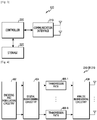
- FIG. 4 illustrates the communication interface in the wireless communication system according to various embodiments of the present disclosure.
- FIG. 4 shows an example for the detailed configuration of the communication interface 210 of FIG. 2 or the communication interface 310 of FIG. 3 . More specifically, FIG. 4 shows elements for performing beamforming as part of the communication interface 210 of FIG. 2 or the communication interface 310 of FIG. 3 .
- the communication interface 210 or 310 includes an encoding and circuitry 402, a digital circuitry 404, a plurality of transmission paths 406-1 to 406-N, and an analog circuitry 408.
- the encoding and circuitry 402 performs channel encoding.
- a low-density parity check (LDPC) code For the channel encoding, at least one of a low-density parity check (LDPC) code, a convolution code, and a polar code may be used.
- the encoding and circuitry 402 generates modulation symbols by performing constellation mapping.
- LDPC low-density parity check
- the digital circuitry 404 performs beamforming for a digital signal (for example, modulation symbols). To this end, the digital circuitry 404 multiples the modulation symbols by beamforming weighted values.
- the beamforming weighted values may be used for changing the size and phrase of the signal, and may be referred to as a "precoding matrix" or a "precoder.”
- the digital circuitry 404 outputs the digitally beamformed modulation symbols to the plurality of transmission paths 406-1 to 406-N.
- the modulation symbols may be multiplexed, or the same modulation symbols may be provided to the plurality of transmission paths 406-1 to 406-N.
- MIMO multiple input multiple output
- the plurality of transmission paths 406-1 to 406-N convert the digitally beamformed digital signals into analog signals.
- each of the plurality of transmission paths 406-1 to 406-N may include an inverse fast Fourier transform (IFFT) calculation unit, a cyclic prefix (CP) insertion unit, a DAC, and an up-conversion unit.
- the CP insertion unit is for an orthogonal frequency division multiplexing (OFDM) scheme, and may be omitted when another physical layer scheme (for example, a filter bank multi-carrier: FBMC) is applied. That is, the plurality of transmission paths 406-1 to 406-N provide independent signal processing processes for a plurality of streams generated through the digital beamforming. However, depending on the implementation, some of the elements of the plurality of transmission paths 406-1 to 406-N may be used in common.
- OFDM orthogonal frequency division multiplexing
- the analog circuitry 408 performs beamforming for analog signals. To this end, the digital circuitry 404 multiples the analog signals by beamforming weighted values. The beamformed weighted values are used for changing the size and phrase of the signal. More specifically, according to a connection structure between the plurality of transmission paths 406-1 to 406-N and antennas, the analog circuitry 408 may be configured in various ways. For example, each of the plurality of transmission paths 406-1 to 406-N may be connected to one antenna array. In another example, the plurality of transmission paths 406-1 to 406-N may be connected to one antenna array. In still another example, the plurality of transmission paths 406-1 to 406-N may be adaptively connected to one antenna array, or may be connected to two or more antenna arrays.
- SR Scheduling Request
- BSR Buffer Status Reporting
- LTE Long Term Evolution
- SR is sent only when the UE does not have enough data allocated on the uplink (UL) shared channel (SCH) to send a BSR.
- SR is a simple one-bit indication that more resource is needed, without saying anything about the amount of resource needed and the Quality of Service (QoS) support required for the data in question. It has already been agreed, at a standardisation level, to support shorter periodicities for SR transmission in NR to help address this problem.
- NR In NR, there is the additional complexity that the radio network will need to support very different types of services. For instance, in NR Phase-I, simultaneous support is guaranteed for enhanced Mobile Broadband (eMBB) and Ultra-Reliable and Low-Latency Communications (URLLC). Based on recent standardisation discussions it is likely that URLLC and eMBB will be deployed using different numerologies.
- eMBB enhanced Mobile Broadband
- URLLC Ultra-Reliable and Low-Latency Communications
- the existing SR/BSR mechanism can therefore be viewed as sub-optimal for multiple numerology support as it lacks support for these features. It should be noted that for a multiple numerology scenario, a UE may not multiplex data from all logical channels into one single MAC Protocol Data Unit (PDU), resulting in inefficiencies if the existing SR/BSR mechanisms are applied in NR.
- PDU Protocol Data Unit
- the existing SR/BSR mechanism can be, in some cases, prohibitive. Some gain could be achieved in the speed (and accuracy) of uplink resource size allocation if the QoS requirements were communicated to the Base Station (gNB) sooner, even when the value of the TTI is fixed.
- Some proposed solutions include multi-bit SR, as well as other alternative solutions.
- the SR resources are dedicated per UE and/or only for the highest priority numerology (the case when single SR resource is configured for multiple services/use cases)
- Embodiments of the disclosure address the case where a single SR resource is configured for multiple services/use cases.
- embodiments of the disclosure allow the network to control SR resource scheduling (e.g. periodicity) dynamically based on the UE's feedback about type (e.g. QCI) of data transmitted in uplink.
- SR resource scheduling e.g. periodicity
- type e.g. QCI
- Embodiments of the disclosure provide a form of SR configuration update or switching, depending on the type of data that the UE wants to transmit.
- One embodiment makes this switch operation faster by utilising MAC CE or DCI-based switching by network rather than making RRC signaling responsible for this switch.
- Option-1 The UE is provided with multiple SR configurations in the first Radio Resource Control (RRC) message and only one of these configurations is activated initially.
- RRC Radio Resource Control
- the network may indicate a change of SR configuration by providing SR configuration index in DCI/MAC Control Elements (CE).
- Option-2 The UE is provided with a single SR configuration in RRC. However, if the network decides to change some parameter (e.g. periodicity), it sends the parameter's value using DCI/MAC CE. For example, the network can change any of the following parameters relating to SR transmission dynamically via DCI/MAC CE:
- the UE is only able (based on MAC CE/DCI messages formats) to indicate some change in parameter of the original configuration (e.g. periodicity) then it may only be possible to provide it with a single configuration (Option-2) or, possibly, multiple configurations but with the understanding that the UE can only indicate incremental parameter-value changes.
- Option-2 may be preferred (or the only one possible).
- limitations in the scope of subsequent changes to the configuration may be less stringent and are concerned with the RRC format of messages used. In an embodiment of this disclosure, these details are taken into account when deciding between Option-1 and Option2, or switching between those two ways of configuring the UE.
- the network configures more than one configuration (such as in the case of multi-numerology scenario) initially.
- the UE could then indicate (e.g. using uplink control information or MAC CE) which ones could be released based on any of the following:
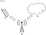
- the base station 20 may be a base station such as a base station 110.
- the base station 20 can then confirm that change with MAC or DCI signaling. Additionally, in some cases (e.g. UEs dedicated to a single type of traffic) these options could be 'preprogrammed' into the UE (e.g. linked to a predefined UE category).
- the UE 10 may be a terminal such as terminal 120 or terminal 130.
- the UE 10 may also have different MAC configuration to control SR transmission (e.g. SR prohibit timer) for different SR configurations. In this case when SR configuration is switched by the network, the UE may apply the new MAC configuration for SR control immediately.
- At least some of the example embodiments described herein may be constructed, partially or wholly, using dedicated special-purpose hardware.
- Terms such as 'component', 'module' or 'unit' used herein may include, but are not limited to, a hardware device, such as circuitry in the form of discrete or integrated components, a Field Programmable Gate Array (FPGA) or Application Specific Integrated Circuit (ASIC), which performs certain tasks or provides the associated functionality.
- FPGA Field Programmable Gate Array
- ASIC Application Specific Integrated Circuit
- the described elements may be configured to reside on a tangible, persistent, addressable storage medium and may be configured to execute on one or more processors.
- These functional elements may in some embodiments include, by way of example, components, such as software components, object-oriented software components, class components and task components, processes, functions, attributes, procedures, subroutines, segments of program code, drivers, firmware, microcode, circuitry, data, databases, data structures, tables, arrays, and variables.
- components such as software components, object-oriented software components, class components and task components, processes, functions, attributes, procedures, subroutines, segments of program code, drivers, firmware, microcode, circuitry, data, databases, data structures, tables, arrays, and variables.
- components such as software components, object-oriented software components, class components and task components, processes, functions, attributes, procedures, subroutines, segments of program code, drivers, firmware, microcode, circuitry, data, databases, data structures, tables, arrays, and variables.
- a computer-readable storage medium for storing one or more programs (software modules) may be provided.
- the one or more programs stored in the computer-readable storage medium may be configured for execution by one or more processors within the electronic device.
- the at least one program may include instructions that cause the electronic device to perform the methods according to various embodiments of the present disclosure as defined by the appended claims and/or disclosed herein.
- the programs may be stored in non-volatile memories including a random access memory and a flash memory, a read only memory (ROM), an electrically erasable programmable read only memory (EEPROM), a magnetic disc storage device, a compact disc-ROM (CD-ROM), digital versatile discs (DVDs), or other type optical storage devices, or a magnetic cassette.
- ROM read only memory
- EEPROM electrically erasable programmable read only memory
- CD-ROM compact disc-ROM
- DVDs digital versatile discs
- any combination of some or all of the may form a memory in which the program is stored.
- a plurality of such memories may be included in the electronic device.
- the programs may be stored in an attachable storage device which is accessible through communication networks such as the Internet, Intranet, local area network (LAN), wide area network (WAN), and storage area network (SAN), or a combination thereof.
- a storage device may access the electronic device via an external port.
- a separate storage device on the communication network may access a portable electronic device.
- a component included in the present disclosure is expressed in the singular or the plural according to a presented detailed embodiment.
- the singular form or plural form is selected for convenience of description suitable for the presented situation, and various embodiments of the present disclosure are not limited to a single element or multiple elements thereof. Further, either multiple elements expressed in the description may be configured into a single element or a single element in the description may be configured into multiple elements.
Landscapes
- Engineering & Computer Science (AREA)
- Signal Processing (AREA)
- Computer Networks & Wireless Communication (AREA)
- Mobile Radio Communication Systems (AREA)
Claims (15)
- Procédé mis en œuvre par un équipement utilisateur, UE, dans un système de communication sans fil, le procédé comprenant :recevoir, depuis une station de base, un message de contrôle de ressources radio, RRC, comprenant des informations sur une pluralité de configurations de demande de programmation, SR ;recevoir, depuis la station de base, des informations de commande de liaison descendante, DCI, comprenant un index associé à une configuration de SR ; ettransmettre, à la station de base, une SR basée sur la configuration de SR parmi les configurations de SR.
- Procédé selon la revendication 1, où l'UE est pourvu de la pluralité de configurations de SR comprenant la configuration de SR par la station de base, et
où au moins l'une de la pluralité de configurations de SR comprend une configuration de SR activée. - Procédé selon la revendication 2, où la configuration de SR activée est déterminée en fonction d'au moins un des facteurs comprenant :un type d'UE ;du trafic en liaison descendante, DL, mis en attente dans des tampons sur la station de base ;des informations relatives aux connexions précédentes de l'UE à un réseau ;des données précédentes transmises sur une liaison montante depuis l'UE ;une charge de signalisation actuelle dans une cellule particulière, ou un groupe de cellules, desservie par la station de base; etdes estimations de la charge de signalisation dans la cellule particulière, ou le groupe de cellules, desservie par la station de base.
- Procédé selon la revendication 3, où un changement d'au moins l'un des facteurs amène la station de base à transmettre un message de reconfiguration à l'UE.
- Procédé selon la revendication 2, comprenant en outre :
transmettre, à la station de base, au moins un des composants dans un groupe d'informations, les composants comprenant :des informations relatives à un type de données dans des tampons de liaison montante, UL, de l'UE ;des informations relatives à des transmissions de données précédentes de l'UE ;des informations relatives à au moins l'une parmi des applications actives ou des exigences d'identifiant de classe de qualité de service, QoS, QCI, qui seront nécessaires ; etdes informations relatives à des aspects architecturaux d'un système connecté connu de l'UE, et moyennant quoi la station de base indique à l'UE quelle configuration de SR utiliser en réponse. - Procédé selon la revendication 5, où un changement dans au moins l'un des composants amène l'UE à transmettre des informations relatives au changement à la station de base, et
recevoir, depuis la station de base, un message de reconfiguration. - Procédé mis en œuvre par une station de base dans un système de communication sans fil, le procédé comprenant :transmettre, à un équipement utilisateur, UE, un message de contrôle de ressources radio, RRC, comprenant des informations sur une pluralité de configurations de demande de programmation, SR ;transmettre, à l'UE, des informations de commande de liaison descendante, DCI, comprenant un index associé à une configuration de SR ; etrecevoir, de l'UE, une SR basée sur la configuration de SR parmi les configurations de SR.
- Procédé selon la revendication 7,où l'UE est pourvu de la pluralité de configurations de SR comprenant la configuration de SR par la station de base, etoù au moins l'une de la pluralité de configurations de SR comprend une configuration de SR activée.
- Procédé selon la revendication 8, comprenant en outre :
transmettre, à l'UE, un message de reconfiguration en réponse à un changement d'au moins l'un des facteurs, les facteurs comprenant :un type d'UE ;du trafic de liaison descendante, DL, mis en attente dans des tampons à la station de base ;des informations relatives aux connexions précédentes de l'UE à un réseau ;des données précédentes transmises sur une liaison montante depuis l'UE ;une charge de signalisation actuelle dans une cellule particulière, ou un groupe de cellules, desservie par la station de base; etdes estimations de la charge de signalisation dans la cellule particulière, ou le groupe de cellules, desservie par la station de base. - Procédé selon la revendication 7, comprenant en outre :
transmettre, à l'UE, une instruction de configuration de SR initiale sur un canal de RRC. - Équipement utilisateur, UE, pour un système de communication sans fil, l'UE comprenant :un émetteur-récepteur ; etau moins un processeur couplé à l'émetteur-récepteur et configuré pour :recevoir, depuis une station de base, un message de contrôle de ressources radio, RRC, comprenant des informations sur une pluralité de configurations de demande de programmation, SR ;recevoir, depuis la station de base, des informations de commande de liaison descendante, DCI, comprenant un index associé à une configuration de SR ; ettransmettre, à la station de base, une SR basée sur la configuration de SR parmi les configurations de SR.
- Station de base pour un système de communication sans fil, la station de base comprenant :un émetteur-récepteur ; etau moins un processeur couplé à l'émetteur-récepteur et configuré pour :transmettre, à un équipement utilisateur, UE, un message de contrôle de ressources radio, RRC, comprenant des informations sur une pluralité de configurations de demande de programmation, SR ;transmettre, à l'UE, des informations de commande de liaison descendante, DCI, comprenant un index associé à une configuration de SR ; etrecevoir, de l'UE, une SR basée sur la configuration de SR parmi les configurations de SR.
- Procédé selon la revendication 1, procédé selon la revendication 7, UE selon la revendication 11, ou station de base selon la revendication 12,où les DCI sont utilisées pour modifier un paramètre pour la configuration de SR, etoù la SR est transmise sur le paramètre modifié avec la configuration de SR.
- Procédé, UE ou station de base selon la revendication 13, où le paramètre est associé à un canal de commande de liaison montante physique, PUCCH.
- Procédé selon la revendication 1, procédé selon la revendication 7, UE selon la revendication 11 ou station de base selon la revendication 12, où la configuration de SR comprend un temporisateur d'interdiction de SR.
Applications Claiming Priority (3)
| Application Number | Priority Date | Filing Date | Title |
|---|---|---|---|
| IN201711010237 | 2017-03-23 | ||
| GB1804428.9A GB2562367B (en) | 2017-03-23 | 2018-03-20 | Improvements in and relating to scheduling requests (SR) in a telecommunication system |
| PCT/KR2018/003479 WO2018174662A1 (fr) | 2017-03-23 | 2018-03-23 | Procédé et appareil de demande de planification dans un système de communication sans fil |
Publications (3)
| Publication Number | Publication Date |
|---|---|
| EP3596992A1 EP3596992A1 (fr) | 2020-01-22 |
| EP3596992A4 EP3596992A4 (fr) | 2020-03-25 |
| EP3596992B1 true EP3596992B1 (fr) | 2021-10-13 |
Family
ID=62017896
Family Applications (1)
| Application Number | Title | Priority Date | Filing Date |
|---|---|---|---|
| EP18770486.1A Active EP3596992B1 (fr) | 2017-03-23 | 2018-03-23 | Procédés et appareils de demande de planification dans un système de communication sans fil |
Country Status (6)
| Country | Link |
|---|---|
| US (1) | US11395321B2 (fr) |
| EP (1) | EP3596992B1 (fr) |
| KR (1) | KR102700046B1 (fr) |
| CN (1) | CN110447291B (fr) |
| GB (1) | GB2562367B (fr) |
| WO (1) | WO2018174662A1 (fr) |
Families Citing this family (2)
| Publication number | Priority date | Publication date | Assignee | Title |
|---|---|---|---|---|
| WO2020251815A1 (fr) | 2019-06-14 | 2020-12-17 | Google Llc | Économie d'énergie dans un dispositif de communication |
| US20240334451A1 (en) * | 2023-03-31 | 2024-10-03 | Qualcomm Incorporated | Techniques for physical uplink control channel adaptation |
Family Cites Families (52)
| Publication number | Priority date | Publication date | Assignee | Title |
|---|---|---|---|---|
| KR101421773B1 (ko) | 2007-06-19 | 2014-07-22 | 텔레폰악티에볼라겟엘엠에릭슨(펍) | 원격 통신 시스템에서의 자원을 스케줄링하기 위한 방법 및 시스템 |
| WO2009084998A1 (fr) * | 2008-01-03 | 2009-07-09 | Telefonaktiebolaget Lm Ericsson (Publ) | Récupération rapide de liaison radio après échec d'un transfert |
| BRPI0908593B1 (pt) * | 2008-03-21 | 2020-12-29 | Telefonaktiebolaget Lm Ericsson (Publ) | método relacionado a comunicações de enlace ascendente de um terminal sem fio, aparelho para uso em um terminal sem fio e sistema de radiocomunicações |
| US8559962B2 (en) * | 2009-01-22 | 2013-10-15 | Innovative Sonic Limited | Method and apparatus for improving reconfiguration procedure for scheduling request |
| EP2469784A4 (fr) * | 2009-08-17 | 2016-01-13 | Lg Electronics Inc | Procédé et appareil d'allocation d'une porteuse de liaison montante pour transmettre des informations de contrôle de liaison montante dans un système de communication sans fil |
| CN102014442B (zh) * | 2009-09-29 | 2014-01-08 | 电信科学技术研究院 | 发送上行资源调度请求的方法和用户设备 |
| CN105306187A (zh) * | 2009-11-19 | 2016-02-03 | 交互数字专利控股公司 | Wtru及在其中实施的用于处理载波聚合的方法 |
| CN101720122B (zh) * | 2009-12-28 | 2015-05-20 | 中兴通讯股份有限公司 | 一种物理上行控制信道的功率控制方法及基站和终端 |
| CN102714565B (zh) * | 2010-01-08 | 2016-03-02 | Lg电子株式会社 | 在支持多载波的无线通信系统中发送上行链路控制信息的方法和装置 |
| KR101782645B1 (ko) * | 2010-01-17 | 2017-09-28 | 엘지전자 주식회사 | 무선 통신 시스템에서 상향링크 제어 정보 전송 방법 및 장치 |
| US9877290B2 (en) * | 2010-04-22 | 2018-01-23 | Sharp Kabushiki Kaisha | Communication method and system for physical uplink control channel resource assignment, and base station, user equipment and integrated circuit therein |
| KR101852814B1 (ko) * | 2010-06-18 | 2018-04-27 | 엘지전자 주식회사 | 무선 통신 시스템에서 단말이 잔여전력 정보를 송신하는 방법 및 이를 위한 장치 |
| MX2013007940A (es) * | 2011-01-07 | 2013-11-01 | Fujitsu Ltd | Metodo para activar un simbolo de referencia de sondeo aperiodico, estacion base y equipo de usuario. |
| US9407390B2 (en) * | 2011-03-23 | 2016-08-02 | Lg Electronics Inc. | Retransmission method for dynamic subframe setting in wireless communication system and apparatus for same |
| KR20120120775A (ko) * | 2011-04-25 | 2012-11-02 | 주식회사 팬택 | 무선통신 시스템에서 제어 정보의 다중 전송을 동적으로 제어하는 방법 및 장치 |
| JP5990815B2 (ja) * | 2011-11-07 | 2016-09-14 | シャープ株式会社 | 基地局、端末、通信システムおよび通信方法 |
| EP2781125A1 (fr) * | 2011-11-16 | 2014-09-24 | Telefonaktiebolaget L M Ericsson (publ) | Procédé et dispositif pour permettre une consommation de batterie réduite dans un terminal mobile |
| US8989122B2 (en) * | 2011-12-23 | 2015-03-24 | Blackberry Limited | Method implemented in a user equipment UE for use in a wireless system |
| US8929319B2 (en) * | 2011-12-23 | 2015-01-06 | Blackberry Limited | Updating scheduling request resources |
| US9088971B2 (en) * | 2011-12-23 | 2015-07-21 | Blackberry Limited | Method implemented in a user equipment |
| US8964679B2 (en) * | 2011-12-23 | 2015-02-24 | Blackberry Limited | Method implemented in an eNodeB base station |
| US9247563B2 (en) * | 2011-12-23 | 2016-01-26 | Blackberry Limited | Method implemented in a user equipment |
| US8964678B2 (en) * | 2011-12-23 | 2015-02-24 | Blackberry Limited | Method implemented in an eNodeB base station |
| WO2013105837A1 (fr) * | 2012-01-15 | 2013-07-18 | 엘지전자 주식회사 | Procédé et appareil pour la transmission de données de contrôle dans un système de communication sans fil |
| WO2013109073A1 (fr) * | 2012-01-17 | 2013-07-25 | 엘지전자 주식회사 | Procédé et appareil pour la transmission d'informations de commande de liaison montante dans un système de communication sans fil |
| WO2013134952A1 (fr) * | 2012-03-16 | 2013-09-19 | 华为技术有限公司 | Procédé, dispositif et système pour affecter des ressources de demande d'ordonnancement |
| JP6167166B2 (ja) * | 2012-03-23 | 2017-07-26 | 聯發科技股▲ふん▼有限公司Mediatek Inc. | 移動通信ネットワークのスケジューリングリクエストリソースを割り当てる方法 |
| WO2013187605A1 (fr) * | 2012-06-15 | 2013-12-19 | 엘지전자 주식회사 | Procédé de détection d'équipement d'utilisateur pour communication directe entre équipements d'utilisateurs dans un système de communications sans fil, et appareil à cet effet |
| KR20130143283A (ko) * | 2012-06-21 | 2013-12-31 | 주식회사 팬택 | 제어 신호 동시 전송 방법, 그 단말, 제어 신호 수신 방법, 및 그 기지국 |
| PL2946608T3 (pl) * | 2013-01-17 | 2018-07-31 | Sun Patent Trust | Dynamiczna konfiguracja uplinku oraz downlinku TDD z wykorzystaniem DCI |
| US20160119940A1 (en) * | 2013-05-15 | 2016-04-28 | Telefonaktiebolaget L M Ericsson (Publ) | Method and bs for identifying ue transmits sr, and method and ue for transmitting sr to bs |
| EP3001580B1 (fr) * | 2013-06-26 | 2019-01-02 | Huawei Technologies Co., Ltd. | Système, dispositif et procédé d'établissement de connexion |
| JP6461812B2 (ja) * | 2013-12-03 | 2019-01-30 | 京セラ株式会社 | ユーザ端末、基地局、及び方法 |
| US10034281B2 (en) * | 2014-03-27 | 2018-07-24 | Lg Electronics Inc. | Method for transmitting and receiving downlink signal in wireless communication system, and device therefor |
| KR101913607B1 (ko) | 2014-07-17 | 2018-10-31 | 엘지전자 주식회사 | 무선 통신 시스템에서 스케줄링 요청 방법 및 이를 위한 장치 |
| WO2016032077A1 (fr) * | 2014-08-25 | 2016-03-03 | Lg Electronics Inc. | Procédé et appareil de demande de planification dans un système de communication sans fil |
| CN106716908B (zh) * | 2014-09-27 | 2020-04-17 | Lg电子株式会社 | 在无线通信系统中发送和接收信号的方法及执行该方法的设备 |
| US10772083B2 (en) * | 2014-12-31 | 2020-09-08 | Lg Electronics Inc. | Method and apparatus for allocating resource in wireless communication system |
| US10575323B2 (en) * | 2015-03-27 | 2020-02-25 | Sharp Kabushiki Kaisha | Systems and methods for a physical uplink control channel on a secondary cell |
| CN106160937B (zh) * | 2015-04-15 | 2019-01-04 | 中兴通讯股份有限公司 | 一种实现码块分割的方法及装置 |
| US10506631B2 (en) * | 2015-04-30 | 2019-12-10 | Lg Electronics Inc. | Method and apparatus for controlling congestion of contention based PUSCH transmission or contention based SR transmission in wireless communication system |
| WO2016190591A1 (fr) * | 2015-05-22 | 2016-12-01 | Lg Electronics Inc. | Procédé de configuration d'autorisations de liaison montante sur une pluralité de sous-trames dans un système de communications sans fil, et dispositif associé |
| US10356631B1 (en) * | 2015-09-03 | 2019-07-16 | Sprint Spectrum L.P. | Method and apparatus for invoking beamforming responsive to carrier transition |
| CN106559198B (zh) * | 2015-09-25 | 2019-09-17 | 电信科学技术研究院 | 一种基于pucch的上行控制信息传输方法及装置 |
| US20170208619A1 (en) * | 2016-01-14 | 2017-07-20 | Qualcomm Incorporated | Scheduling request during connected discontinuous reception off period |
| US10548169B2 (en) * | 2016-02-02 | 2020-01-28 | Lg Electronics Inc. | Method and device for transmitting/receiving wireless signal in wireless communication system |
| US11206639B2 (en) * | 2016-02-24 | 2021-12-21 | Lg Electronics Inc. | Method and device for transmitting scheduling request in wireless communication system |
| KR102288627B1 (ko) * | 2016-03-02 | 2021-08-11 | 삼성전자 주식회사 | 통신 시스템에서 단말의 상향링크 제어 정보 전송 방법 및 장치 |
| US10547426B2 (en) * | 2016-03-14 | 2020-01-28 | Samsung Electronics Co., Ltd. | Transmission of sounding reference signals in communication systems with carrier aggregation |
| EP3469843B1 (fr) * | 2016-06-08 | 2023-03-08 | Telefonaktiebolaget LM Ericsson (publ) | Systèmes et procédés de signalisation et d'utilisation de motifs de transmission |
| US10932240B2 (en) * | 2016-11-01 | 2021-02-23 | Lg Electronics Inc. | Method for transmitting SR in wireless communication system and terminal therefor |
| US11184098B2 (en) * | 2017-03-22 | 2021-11-23 | Lg Electronics Inc. | Method for controlling inter-cell interference in wireless communication system, and device therefor |
-
2018
- 2018-03-20 GB GB1804428.9A patent/GB2562367B/en active Active
- 2018-03-23 WO PCT/KR2018/003479 patent/WO2018174662A1/fr not_active Ceased
- 2018-03-23 CN CN201880018688.2A patent/CN110447291B/zh active Active
- 2018-03-23 US US16/496,909 patent/US11395321B2/en active Active
- 2018-03-23 EP EP18770486.1A patent/EP3596992B1/fr active Active
- 2018-03-23 KR KR1020197027812A patent/KR102700046B1/ko active Active
Also Published As
| Publication number | Publication date |
|---|---|
| GB2562367A (en) | 2018-11-14 |
| GB201804428D0 (en) | 2018-05-02 |
| US11395321B2 (en) | 2022-07-19 |
| US20200107350A1 (en) | 2020-04-02 |
| GB2562367B (en) | 2021-03-10 |
| EP3596992A4 (fr) | 2020-03-25 |
| KR102700046B1 (ko) | 2024-08-29 |
| WO2018174662A1 (fr) | 2018-09-27 |
| EP3596992A1 (fr) | 2020-01-22 |
| CN110447291B (zh) | 2023-04-28 |
| KR20190123754A (ko) | 2019-11-01 |
| CN110447291A (zh) | 2019-11-12 |
Similar Documents
| Publication | Publication Date | Title |
|---|---|---|
| US12192866B2 (en) | Apparatus and method for configuring and managing quality of service of radio bearer for direct communication in wireless communication system | |
| US11082103B2 (en) | Apparatus and method for beam management in wireless communication system | |
| US12155596B2 (en) | Method and apparatus for configuring and signaling PTRS in a telecommunication system | |
| EP3902364B1 (fr) | Procédés et appareils de demande d'ordonnancement dans un système de communication sans fil | |
| US20210410162A1 (en) | Apparatus and method for selecting radio access technology for direct communication between terminals in wireless communication system | |
| EP3707850B1 (fr) | Procédé et appareil pour améliorer et se rapportant à un accès intégré et à des réseaux terrestres et non terrestres | |
| EP3689014B1 (fr) | Identifiant de modèle de terminal dans une demande d'établissement de connexion pour la fourniture de capacités | |
| KR20210038141A (ko) | 무선 통신 시스템에서 컴퓨팅 구조 및 무선 통신 프로토콜 구조의 결정을 위한 방법 및 장치 | |
| EP3777001B1 (fr) | Procédé et appareil pour améliorer et se rapportant à des signaux de référence dans un réseau de télécommunication | |
| EP3596992B1 (fr) | Procédés et appareils de demande de planification dans un système de communication sans fil | |
| KR20220135049A (ko) | 무선 통신 시스템에서 우선순위에 기초하여 사이드링크 릴레이 탐색 메시지를 전송하는 방법 및 장치 | |
| KR20210039918A (ko) | 단말 간 무선 직접 통신 시스템에서 pdcp 계층의 비순차적 전송을 처리하는 방법 및 장치 | |
| KR102862764B1 (ko) | 무선 통신 시스템에서 전송들의 충돌을 처리하기 위한 장치 및 방법 |
Legal Events
| Date | Code | Title | Description |
|---|---|---|---|
| STAA | Information on the status of an ep patent application or granted ep patent |
Free format text: STATUS: THE INTERNATIONAL PUBLICATION HAS BEEN MADE |
|
| PUAI | Public reference made under article 153(3) epc to a published international application that has entered the european phase |
Free format text: ORIGINAL CODE: 0009012 |
|
| STAA | Information on the status of an ep patent application or granted ep patent |
Free format text: STATUS: REQUEST FOR EXAMINATION WAS MADE |
|
| 17P | Request for examination filed |
Effective date: 20191018 |
|
| AK | Designated contracting states |
Kind code of ref document: A1 Designated state(s): AL AT BE BG CH CY CZ DE DK EE ES FI FR GB GR HR HU IE IS IT LI LT LU LV MC MK MT NL NO PL PT RO RS SE SI SK SM TR |
|
| AX | Request for extension of the european patent |
Extension state: BA ME |
|
| A4 | Supplementary search report drawn up and despatched |
Effective date: 20200225 |
|
| RIC1 | Information provided on ipc code assigned before grant |
Ipc: H04W 72/12 20090101AFI20200219BHEP |
|
| DAV | Request for validation of the european patent (deleted) | ||
| DAX | Request for extension of the european patent (deleted) | ||
| GRAP | Despatch of communication of intention to grant a patent |
Free format text: ORIGINAL CODE: EPIDOSNIGR1 |
|
| STAA | Information on the status of an ep patent application or granted ep patent |
Free format text: STATUS: GRANT OF PATENT IS INTENDED |
|
| INTG | Intention to grant announced |
Effective date: 20210604 |
|
| GRAS | Grant fee paid |
Free format text: ORIGINAL CODE: EPIDOSNIGR3 |
|
| GRAA | (expected) grant |
Free format text: ORIGINAL CODE: 0009210 |
|
| STAA | Information on the status of an ep patent application or granted ep patent |
Free format text: STATUS: THE PATENT HAS BEEN GRANTED |
|
| AK | Designated contracting states |
Kind code of ref document: B1 Designated state(s): AL AT BE BG CH CY CZ DE DK EE ES FI FR GB GR HR HU IE IS IT LI LT LU LV MC MK MT NL NO PL PT RO RS SE SI SK SM TR |
|
| REG | Reference to a national code |
Ref country code: GB Ref legal event code: FG4D |
|
| REG | Reference to a national code |
Ref country code: CH Ref legal event code: EP |
|
| REG | Reference to a national code |
Ref country code: DE Ref legal event code: R096 Ref document number: 602018025055 Country of ref document: DE |
|
| REG | Reference to a national code |
Ref country code: IE Ref legal event code: FG4D |
|
| REG | Reference to a national code |
Ref country code: AT Ref legal event code: REF Ref document number: 1439096 Country of ref document: AT Kind code of ref document: T Effective date: 20211115 |
|
| REG | Reference to a national code |
Ref country code: NL Ref legal event code: FP |
|
| REG | Reference to a national code |
Ref country code: LT Ref legal event code: MG9D |
|
| REG | Reference to a national code |
Ref country code: AT Ref legal event code: MK05 Ref document number: 1439096 Country of ref document: AT Kind code of ref document: T Effective date: 20211013 |
|
| PG25 | Lapsed in a contracting state [announced via postgrant information from national office to epo] |
Ref country code: RS Free format text: LAPSE BECAUSE OF FAILURE TO SUBMIT A TRANSLATION OF THE DESCRIPTION OR TO PAY THE FEE WITHIN THE PRESCRIBED TIME-LIMIT Effective date: 20211013 Ref country code: LT Free format text: LAPSE BECAUSE OF FAILURE TO SUBMIT A TRANSLATION OF THE DESCRIPTION OR TO PAY THE FEE WITHIN THE PRESCRIBED TIME-LIMIT Effective date: 20211013 Ref country code: FI Free format text: LAPSE BECAUSE OF FAILURE TO SUBMIT A TRANSLATION OF THE DESCRIPTION OR TO PAY THE FEE WITHIN THE PRESCRIBED TIME-LIMIT Effective date: 20211013 Ref country code: BG Free format text: LAPSE BECAUSE OF FAILURE TO SUBMIT A TRANSLATION OF THE DESCRIPTION OR TO PAY THE FEE WITHIN THE PRESCRIBED TIME-LIMIT Effective date: 20220113 Ref country code: AT Free format text: LAPSE BECAUSE OF FAILURE TO SUBMIT A TRANSLATION OF THE DESCRIPTION OR TO PAY THE FEE WITHIN THE PRESCRIBED TIME-LIMIT Effective date: 20211013 |
|
| PG25 | Lapsed in a contracting state [announced via postgrant information from national office to epo] |
Ref country code: IS Free format text: LAPSE BECAUSE OF FAILURE TO SUBMIT A TRANSLATION OF THE DESCRIPTION OR TO PAY THE FEE WITHIN THE PRESCRIBED TIME-LIMIT Effective date: 20220213 Ref country code: SE Free format text: LAPSE BECAUSE OF FAILURE TO SUBMIT A TRANSLATION OF THE DESCRIPTION OR TO PAY THE FEE WITHIN THE PRESCRIBED TIME-LIMIT Effective date: 20211013 Ref country code: PT Free format text: LAPSE BECAUSE OF FAILURE TO SUBMIT A TRANSLATION OF THE DESCRIPTION OR TO PAY THE FEE WITHIN THE PRESCRIBED TIME-LIMIT Effective date: 20220214 Ref country code: PL Free format text: LAPSE BECAUSE OF FAILURE TO SUBMIT A TRANSLATION OF THE DESCRIPTION OR TO PAY THE FEE WITHIN THE PRESCRIBED TIME-LIMIT Effective date: 20211013 Ref country code: NO Free format text: LAPSE BECAUSE OF FAILURE TO SUBMIT A TRANSLATION OF THE DESCRIPTION OR TO PAY THE FEE WITHIN THE PRESCRIBED TIME-LIMIT Effective date: 20220113 Ref country code: LV Free format text: LAPSE BECAUSE OF FAILURE TO SUBMIT A TRANSLATION OF THE DESCRIPTION OR TO PAY THE FEE WITHIN THE PRESCRIBED TIME-LIMIT Effective date: 20211013 Ref country code: HR Free format text: LAPSE BECAUSE OF FAILURE TO SUBMIT A TRANSLATION OF THE DESCRIPTION OR TO PAY THE FEE WITHIN THE PRESCRIBED TIME-LIMIT Effective date: 20211013 Ref country code: GR Free format text: LAPSE BECAUSE OF FAILURE TO SUBMIT A TRANSLATION OF THE DESCRIPTION OR TO PAY THE FEE WITHIN THE PRESCRIBED TIME-LIMIT Effective date: 20220114 Ref country code: ES Free format text: LAPSE BECAUSE OF FAILURE TO SUBMIT A TRANSLATION OF THE DESCRIPTION OR TO PAY THE FEE WITHIN THE PRESCRIBED TIME-LIMIT Effective date: 20211013 |
|
| REG | Reference to a national code |
Ref country code: DE Ref legal event code: R097 Ref document number: 602018025055 Country of ref document: DE |
|
| PG25 | Lapsed in a contracting state [announced via postgrant information from national office to epo] |
Ref country code: SM Free format text: LAPSE BECAUSE OF FAILURE TO SUBMIT A TRANSLATION OF THE DESCRIPTION OR TO PAY THE FEE WITHIN THE PRESCRIBED TIME-LIMIT Effective date: 20211013 Ref country code: SK Free format text: LAPSE BECAUSE OF FAILURE TO SUBMIT A TRANSLATION OF THE DESCRIPTION OR TO PAY THE FEE WITHIN THE PRESCRIBED TIME-LIMIT Effective date: 20211013 Ref country code: RO Free format text: LAPSE BECAUSE OF FAILURE TO SUBMIT A TRANSLATION OF THE DESCRIPTION OR TO PAY THE FEE WITHIN THE PRESCRIBED TIME-LIMIT Effective date: 20211013 Ref country code: EE Free format text: LAPSE BECAUSE OF FAILURE TO SUBMIT A TRANSLATION OF THE DESCRIPTION OR TO PAY THE FEE WITHIN THE PRESCRIBED TIME-LIMIT Effective date: 20211013 Ref country code: DK Free format text: LAPSE BECAUSE OF FAILURE TO SUBMIT A TRANSLATION OF THE DESCRIPTION OR TO PAY THE FEE WITHIN THE PRESCRIBED TIME-LIMIT Effective date: 20211013 Ref country code: CZ Free format text: LAPSE BECAUSE OF FAILURE TO SUBMIT A TRANSLATION OF THE DESCRIPTION OR TO PAY THE FEE WITHIN THE PRESCRIBED TIME-LIMIT Effective date: 20211013 |
|
| PLBE | No opposition filed within time limit |
Free format text: ORIGINAL CODE: 0009261 |
|
| STAA | Information on the status of an ep patent application or granted ep patent |
Free format text: STATUS: NO OPPOSITION FILED WITHIN TIME LIMIT |
|
| 26N | No opposition filed |
Effective date: 20220714 |
|
| PG25 | Lapsed in a contracting state [announced via postgrant information from national office to epo] |
Ref country code: MC Free format text: LAPSE BECAUSE OF FAILURE TO SUBMIT A TRANSLATION OF THE DESCRIPTION OR TO PAY THE FEE WITHIN THE PRESCRIBED TIME-LIMIT Effective date: 20211013 Ref country code: AL Free format text: LAPSE BECAUSE OF FAILURE TO SUBMIT A TRANSLATION OF THE DESCRIPTION OR TO PAY THE FEE WITHIN THE PRESCRIBED TIME-LIMIT Effective date: 20211013 |
|
| REG | Reference to a national code |
Ref country code: CH Ref legal event code: PL |
|
| PG25 | Lapsed in a contracting state [announced via postgrant information from national office to epo] |
Ref country code: SI Free format text: LAPSE BECAUSE OF FAILURE TO SUBMIT A TRANSLATION OF THE DESCRIPTION OR TO PAY THE FEE WITHIN THE PRESCRIBED TIME-LIMIT Effective date: 20211013 |
|
| REG | Reference to a national code |
Ref country code: BE Ref legal event code: MM Effective date: 20220331 |
|
| PG25 | Lapsed in a contracting state [announced via postgrant information from national office to epo] |
Ref country code: LU Free format text: LAPSE BECAUSE OF NON-PAYMENT OF DUE FEES Effective date: 20220323 Ref country code: LI Free format text: LAPSE BECAUSE OF NON-PAYMENT OF DUE FEES Effective date: 20220331 Ref country code: IE Free format text: LAPSE BECAUSE OF NON-PAYMENT OF DUE FEES Effective date: 20220323 Ref country code: CH Free format text: LAPSE BECAUSE OF NON-PAYMENT OF DUE FEES Effective date: 20220331 |
|
| PG25 | Lapsed in a contracting state [announced via postgrant information from national office to epo] |
Ref country code: BE Free format text: LAPSE BECAUSE OF NON-PAYMENT OF DUE FEES Effective date: 20220331 |
|
| PG25 | Lapsed in a contracting state [announced via postgrant information from national office to epo] |
Ref country code: IT Free format text: LAPSE BECAUSE OF FAILURE TO SUBMIT A TRANSLATION OF THE DESCRIPTION OR TO PAY THE FEE WITHIN THE PRESCRIBED TIME-LIMIT Effective date: 20211013 |
|
| PG25 | Lapsed in a contracting state [announced via postgrant information from national office to epo] |
Ref country code: MK Free format text: LAPSE BECAUSE OF FAILURE TO SUBMIT A TRANSLATION OF THE DESCRIPTION OR TO PAY THE FEE WITHIN THE PRESCRIBED TIME-LIMIT Effective date: 20211013 Ref country code: CY Free format text: LAPSE BECAUSE OF FAILURE TO SUBMIT A TRANSLATION OF THE DESCRIPTION OR TO PAY THE FEE WITHIN THE PRESCRIBED TIME-LIMIT Effective date: 20211013 |
|
| PG25 | Lapsed in a contracting state [announced via postgrant information from national office to epo] |
Ref country code: HU Free format text: LAPSE BECAUSE OF FAILURE TO SUBMIT A TRANSLATION OF THE DESCRIPTION OR TO PAY THE FEE WITHIN THE PRESCRIBED TIME-LIMIT; INVALID AB INITIO Effective date: 20180323 |
|
| PG25 | Lapsed in a contracting state [announced via postgrant information from national office to epo] |
Ref country code: MT Free format text: LAPSE BECAUSE OF FAILURE TO SUBMIT A TRANSLATION OF THE DESCRIPTION OR TO PAY THE FEE WITHIN THE PRESCRIBED TIME-LIMIT Effective date: 20211013 |
|
| PG25 | Lapsed in a contracting state [announced via postgrant information from national office to epo] |
Ref country code: TR Free format text: LAPSE BECAUSE OF FAILURE TO SUBMIT A TRANSLATION OF THE DESCRIPTION OR TO PAY THE FEE WITHIN THE PRESCRIBED TIME-LIMIT Effective date: 20211013 |
|
| PGFP | Annual fee paid to national office [announced via postgrant information from national office to epo] |
Ref country code: NL Payment date: 20260220 Year of fee payment: 9 |
|
| PGFP | Annual fee paid to national office [announced via postgrant information from national office to epo] |
Ref country code: GB Payment date: 20260224 Year of fee payment: 9 |
|
| PGFP | Annual fee paid to national office [announced via postgrant information from national office to epo] |
Ref country code: DE Payment date: 20260220 Year of fee payment: 9 |
|
| PGFP | Annual fee paid to national office [announced via postgrant information from national office to epo] |
Ref country code: FR Payment date: 20260224 Year of fee payment: 9 |