EP3597360A1 - Ensemble d'usinage pour traiter un panneau - Google Patents
Ensemble d'usinage pour traiter un panneau Download PDFInfo
- Publication number
- EP3597360A1 EP3597360A1 EP19187402.3A EP19187402A EP3597360A1 EP 3597360 A1 EP3597360 A1 EP 3597360A1 EP 19187402 A EP19187402 A EP 19187402A EP 3597360 A1 EP3597360 A1 EP 3597360A1
- Authority
- EP
- European Patent Office
- Prior art keywords
- shaft
- tool
- operating position
- machining assembly
- chamber
- Prior art date
- Legal status (The legal status is an assumption and is not a legal conclusion. Google has not performed a legal analysis and makes no representation as to the accuracy of the status listed.)
- Granted
Links
Images




Classifications
-
- B—PERFORMING OPERATIONS; TRANSPORTING
- B27—WORKING OR PRESERVING WOOD OR SIMILAR MATERIAL; NAILING OR STAPLING MACHINES IN GENERAL
- B27C—PLANING, DRILLING, MILLING, TURNING OR UNIVERSAL MACHINES FOR WOOD OR SIMILAR MATERIAL
- B27C3/00—Drilling machines or drilling devices; Equipment therefor
- B27C3/04—Stationary drilling machines with a plurality of working spindles
-
- B—PERFORMING OPERATIONS; TRANSPORTING
- B23—MACHINE TOOLS; METAL-WORKING NOT OTHERWISE PROVIDED FOR
- B23Q—DETAILS, COMPONENTS, OR ACCESSORIES FOR MACHINE TOOLS, e.g. ARRANGEMENTS FOR COPYING OR CONTROLLING; MACHINE TOOLS IN GENERAL CHARACTERISED BY THE CONSTRUCTION OF PARTICULAR DETAILS OR COMPONENTS; COMBINATIONS OR ASSOCIATIONS OF METAL-WORKING MACHINES, NOT DIRECTED TO A PARTICULAR RESULT
- B23Q11/00—Accessories fitted to machine tools for keeping tools or parts of the machine in good working condition or for cooling work; Safety devices specially combined with or arranged in, or specially adapted for use in connection with, machine tools
- B23Q11/0042—Devices for removing chips
- B23Q11/005—Devices for removing chips by blowing
-
- B—PERFORMING OPERATIONS; TRANSPORTING
- B23—MACHINE TOOLS; METAL-WORKING NOT OTHERWISE PROVIDED FOR
- B23Q—DETAILS, COMPONENTS, OR ACCESSORIES FOR MACHINE TOOLS, e.g. ARRANGEMENTS FOR COPYING OR CONTROLLING; MACHINE TOOLS IN GENERAL CHARACTERISED BY THE CONSTRUCTION OF PARTICULAR DETAILS OR COMPONENTS; COMBINATIONS OR ASSOCIATIONS OF METAL-WORKING MACHINES, NOT DIRECTED TO A PARTICULAR RESULT
- B23Q5/00—Driving or feeding mechanisms; Control arrangements therefor
- B23Q5/22—Feeding members carrying tools or work
- B23Q5/26—Fluid-pressure drives
- B23Q5/261—Fluid-pressure drives for spindles
Definitions
- This invention relates to a machining assembly for processing a semi-finished product.
- the invention relates to a machining assembly for the processing for removing, in particular for perforating, panels, in particular panels made of wood or similar materials or materials replacing wood.
- FIG. 1 An example of a prior art perforating unit according to the technical teachings of the above-mentioned patents can be seen in Figure 1 .
- the perforating unit G is equipped with a plurality of spindle shafts M arranged alongside each other ( Figure 1 shows by way of example a perforating unit comprising a single spindle shaft M), according to a particular arrangement which depends on the type of perforating to be performed.
- Each spindle shaft M is designed to receive and support in rotation a shank of a perforating tool (not illustrated).
- the spindle shafts M are arranged so as to be actuated independently towards or away from the piece to be perforated by a piston body P, such as, for example, a pneumatic piston, and by a return spring.
- a piston body P such as, for example, a pneumatic piston
- the perforating unit G also comprises a control and management device, designed to independently control each piston body P for making the desired perforation.
- a problem of the prior art perforating units is the formation of a large quantity of swarf following the removal of material, for example by perforating, especially when there are several perforating tools.
- the swarf is generally sucked by means of special suction systems, however swarf can remain in the holes or cuts made in the semi-finished products.
- the Chinese patent CN 201405404 Y describes a similar solution, wherein the tool is equipped with a channel through which compressed air is blown to remove the swarf formed by the perforating or cutting of the semi-finished products.
- the compressed air is transferred from the chamber fed pneumatically to the through channel in the tool through a gap between the outer body tool-holder shaft and a through channel in said shaft, communicating with said channel in the tool.
- the aim of this invention is to resolve the problems of the prior art, by means of a solution which reduces the need for manual intervention by operators for the removal of swarf formed by the perforation.
- a further aim of the invention is to maintain low the overall size of the machining assembly and the complexity of the system.
- the object of the invention is a machining assembly for processing a semi-finished product, said machining assembly comprising: at least one shaft having a longitudinal axis, a first end or tool-holder end for supporting a machine tool, and a second end, opposite the first end along said longitudinal axis; a support head in which is formed at least one longitudinal housing for housing said a least one shaft; said at least one shaft being movable from a first non-operating position to a second operating position, and vice versa, along said longitudinal axis partially inside said longitudinal housing; a chamber of said longitudinal housing being designed to be fed pneumatically by means of a gas, in particular compressed gas, preferably compressed air, for acting on said second end of said at least one shaft for moving it from said non-operating position to said operating position, or vice versa; said at least one shaft having a first channel passing between said two ends, in order to put in fluid communication said chamber with a first hole formed in said tool-holder end, said machining assembly being configured in such a way that when said chamber is
- At the second end of the at least one shaft there can be a piston body designed to move said at least one shaft and to slide in said chamber in an integral fashion with said at least one shaft, said piston body having a longitudinal hole, parallel to said longitudinal axis, not closed and designed for the passage of said gas, when the chamber is fed pneumatically, from the chamber to the first through channel of said at least one shaft, said machining assembly being configured in such a way that when said chamber is fed pneumatically, said gas acts on said piston body for moving said at least one shaft from said first non-operating position to said second operating position, and said gas passes from said chamber to said first through channel through said longitudinal hole of said piston body.
- At the second end of the at least one shaft there can be a piston body designed to move said at least one shaft and to slide in said chamber in an integral fashion with said at least one shaft, at the second end of the at least one shaft a channel can be made in the body of the at least one shaft and designed for the passage of said gas, when the chamber is fed pneumatically, from the chamber to the through channel of said at least one shaft, said machining assembly being configured in such a way that when said chamber is fed pneumatically, said gas acts on said piston body for moving said at least one shaft from said second operating position to said first non-operating position, and said gas passes from said chamber to said through channel through said channel formed in the body of the at least one shaft.
- said machining assembly can comprise a tool for processing said semi-finished product for removing material, said tool having at the two ends, along the relative longitudinal axis, respectively, a tip and a coupling head, said tool being removably coupled to the tool-holder end of said at least one shaft by means of said coupling head, said machining assembly being configured in such a way that when said tool is coupled to said at least shaft and when the chamber is fed pneumatically, the shaft passes from said first non-operating position to said second operating position, or vice versa, the tip of the tool is able to act on the semi-finished product for removing material, and said gas flowing out is able to evacuate the material removed.
- said tool can comprise at least one through hole in the body of said tool from said tip to said coupling head, said tool being configured in such a way that when it is coupled to said shaft said through hole is in fluid communication with the first through channel of said shaft through said first hole formed in said tool-holder end in such a way that when the chamber is fed pneumatically, the shaft passes from said first non-operating position to said second operating position, or vice versa, the tip of the tool is able to act on the semi-finished product to remove material, and said gas flows from said through hole to evacuate the material removed.
- said at least one shaft can comprise one or more mini-channels in fluid communication with said first hole formed in the tool-holder end, and said machining assembly can configured in such a way that, during use, when a tool is coupled to the tool-holder end and the spindle shaft is in said second operating position, said fluid flows out from said one or more mini-channels.
- said housing can be in fluid communication with said first hole of said through channel formed in said tool-holder end.
- said housing there can be an inner radial seat and a gasket, in particular an O-ring gasket, housed in said radial seat.
- a gasket in particular an O-ring gasket
- said tool can comprise a gasket at said coupling head.
- a portion of the first through channel of the shaft can have a smaller diameter than the diameter of the remaining portion of said through channel in order to calibrate the flow of the gas from the chamber to the first through channel.
- said smaller diameter portion of the first through channel can correspond to its end portion at the second end of the shaft.
- At the second end of the shaft there can be a screw pin which can be removably coupled to said second end of the shaft.
- said machining assembly can comprise at least two shafts, in particular at least two spindle shafts, which can be individually selected.
- said machining assembly can comprise a control and management device for individually controlling each shaft.
- said machining assembly can comprise at the tool-holder end of the shaft a tool-holder head for holding at least one tool.
- said tool-holder head can comprise a further hole and a further through channel, designed to place in fluid communication said first hole formed in said tool-holder end with said further hole formed in said tool-holder head, said machining assembly being configured in such a way that when said chamber is fed pneumatically, said at least one shaft moves from said first non-operating position to said second operating position, or vice versa, and said gas, flowing from said further hole, or in transit through it to subsequently flow from said machining assembly, is able to evacuate the removed material.
- said machining assembly can comprise a tool removably coupled to said tool-holder head and can be configured in such a way as to be positioned in said tool-holder head, with the relative longitudinal axis normal to said longitudinal axis of said at least one shaft.
- said machining assembly can comprise a pair of shafts positioned with the relative axes parallel to each other, and actuated in a substantially synchronous fashion when passing from said first non-operating position to said second operating position, or vice versa, and said tool-holder head can be fixed to each of said shafts, in such a way that when passing between said first non-operating position and second operating position, or vice versa, said tool-holder head performs a translational movement parallel to said longitudinal axis.
- said machining assembly can comprise movement means comprising a shaft for transmission of the rotational motion
- said tool-holder head can comprise means for transmission of said rotational motion from said movement means to said tool.
- said shaft for transmission of the rotational motion can be interposed between said pair of shafts, and in that said shaft for transmission of the rotational motion can comprise telescopic means in such a way as to be designed to transmit continuously a rotational motion by means of said transmission means when said shaft, pass, in a substantially synchronous fashion, from said first non-operating position to said second operating position, or vice versa.
- said tool-holder head there can be a further channel which is able to place in fluid communication said through channels in two or more tools supported by said tool-holder head.
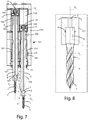
- Figures 2 - 4 show the machining assembly according to the invention labelled 101 in a first embodiment.
- the machining assembly 101 is configured for processing a semi-finished product, for example a panel made of wood or other materials, for removing material.
- Said machining assembly 101 comprises a shaft 102, in the particular embodiment a spindle shaft 102, having a longitudinal axis X 1 , a first end or tool-side end 103 for supporting a machining tool 1, and a second end 106, opposite to the first end 103 along said longitudinal axis X 1 .
- said tool-side end 103 is also called tool-holder end 103 as it directly supports a tool 1.
- said machining assembly 101 comprises a support head 105 in which is formed a longitudinal housing 104 for housing the respective spindle shaft 102.
- Each spindle shaft 102 is movable from a first position, in particular a first non-operating position, to a second operating position, and vice versa, along said longitudinal axis X 1 partially inside said longitudinal housing 104.
- the processing of the semi-finished product for removing material can occur in the second operating position.
- a portion or chamber 133 of said longitudinal housing 104 is designed to be fed pneumatically by means of a fluid, in particular a gas, in particular compressed gas, preferably compressed air, for acting on said second end 106 of said spindle shaft 102 for moving it from said first position to said second operating position, and vice versa.
- a fluid in particular a gas, in particular compressed gas, preferably compressed air
- Said spindle shaft 102 has a through channel 2 passing between said two ends 103, 106, in order to put in fluid communication said chamber 133 with a hole formed in said tool-holder end 103.
- Said machining assembly 101 is configured in such a way that when the chamber 133 is fed pneumatically, the spindle shaft 102 passes fro the first position to the operating position and the gas, and in particular the compressed gas in said chamber 133, flows out by means of said hole of said tool-holder end 103.
- the gas can flow out also or only when the spindle shaft 102 passes from the second operating position to the first non-operating position.
- the tool 1 to be used with the machining assembly 101 according to the invention is designed for the processing of a semi-finished product for removing material, in particular swarf.
- the tool 1 has at the two ends, along the relative longitudinal axis Y 1 , a tip 3 and a coupling head or shank 4. Said tool 1 can be removably coupled to the tool-holder end 103 of said spindle shaft 102 by means of said coupling head 4.
- Said machining assembly 101 is therefore configured in such a way that when said tool 1 is coupled to said spindle shaft 102 and when the chamber 133 is fed pneumatically, the spindle shaft 102 passes to said operating position, the tip 3 of the tool 1 is able to act on the semi-finished product for removing material, and said gas flowing out is able to evacuate the material removed.
- the tool 1 comprises a through hole 5, 6, in the relative body, fro said tip 3 to said coupling head 4.
- the tool 1 is configured in such a way that when it is coupled with said spindle shaft 102 said through hole 5, 6 is in fluid communication with the through channel 2 of said spindle shaft 102 at the hold formed in said tool-holder end 103 in such a way that when the chamber 133 is fed pneumatically, the spindle shaft 102 is in the operating position, the tip 3 of the tool 1 can act on the semi-finished product for removing material, in particular swarf, the compressed gas can also flow from said through hole 5, 6 for evacuating the material removed.
- the compressed gas used for the selection of the spindle 102 to be used causing a movement to the operating position (ON position) holds the spindle 10 stationary in the operating position thanks to the pressure maintained in the chamber 133, guaranteeing the perforating thrust.
- part of the compressed gas flows out from the channel 102, suitably calibrated, without generating an excessive pressure drop in the chamber 133 and/or in any case guaranteeing the required working pressure.
- the user device is therefore controlled simultaneously by the same spindle selection valve, and like the chamber 133 is pressurised, the spindle 102 passes to the operating position and simultaneously starts to blow air from the tip of the tool 1.
- the invention therefore advantageously allows the pneumatic chamber already present in the machining assembly to be used, without the need to use further devices. This also allows the overall dimensions of the machining assembly to be reduced.
- the through hole of the tool 1 can have a first central portion 5 at the coupling head 4 and a second portion with a smaller diameter or o mini-channel 6 at the tip 2 in fluid communication with said first portion 5.
- Several through holes can be provided in other embodiments.
- the through channel 2 of the spindle shaft 102 can be in fluid communication with said through hole at the housing 7.
- the hole formed in the tool-holder end 103 can be in fluid communication with said housing 7 and therefore in fluid communication with the through hole of said tool 1 allowing the passage of the compressed gas for the evacuation of the material removed by the tool 1.
- said housing 7 there can be an inner radial seat 8 and a gasket 9, in particular an O-ring gasket, housed in said radial seat 8.
- said gasket can be positioned directly on the coupling head 4 of the tool 1.
- the presence of the gasket 9 advantageously avoids that the compressed gas which flows out from the through channel 2 to the through hole 5, 6 of the tool 1 flows out from the tool-holder end 103.
- a piston body 130 designed to move the spindle shaft 102 and slide in said chamber 133, in an integral fashion with said at least one shaft 102.
- said gas acts on said piston body 130, in particular on the relative upper portion, for moving said at least one shaft 102 from said first operating position to said first non-operating position.
- Said piston body 130 has a longitudinal hole 10 not closed (unlike the prior art devices) which puts in fluid communication the chamber 133 with the through channel 2.
- the longitudinal hole 10 formed in the piston body 130 allows the passage of the compressed gas from the chamber 133 to the through channel 2 of the spindle shaft 102.
- an end portion 11 of the through channel 2 of the spindle shaft 102, at the second end 106, can have a smaller diameter than the diameter of the remaining portion of said through channel 2 in order to calibrate the flow of the gas from the chamber 133 in the through channel 2.
- the calibration enables the pressure-flow rate ratio of compressed gas to be guaranteed when it flows out from the first end 103 of the spindle 102, maintaining a non-excessive pressure drop in the chamber 133.
- the pressure in the chamber 133 must guarantee an adequate thrust to the spindle 102 in the operating position, as a reaction thrust to the perforating.
- this calibration zone which comprises a portion with a diameter smaller than the rest of the through channel can be provided in other portions of the through channel itself.
- a screw pin 166 which can be removably coupled to said second end 106 of the spindle shaft 102, in particular inside the piston body 130.
- the end portion 11 of the through channel 2 is formed in said screw pin 166.
- the gasket 13 can be made of PTFE.
- machining assembly 101 which comprises at least one spindle shaft 102; other embodiments can comprise several spindle shafts 102, as in the embodiment shown in Figures 5 and 6 .
- the machining assembly 101 can be configured in such a way as to select each independently from the other.
- the machining assembly 101 can comprise a control and management device for individually controlling each spindle shaft 102.
- the method for processing a semi-finished product by means of the machining assembly 101 according to the invention can comprise the following steps:
- the machining assembly is configured for selecting the spindles to be used for the perforating, generating the preferred perforating layout; an axis control or pneumatic machine will then preferably be used to move the entire machining assembly to perform the stroke which generates the hole or the holes on the semi-finished product according to the preselected layout by means of the selected spindles.
- FIG 10 shows a further embodiment of the machining assembly 101 according to the invention.
- Said machining assembly 101 differs from the embodiment described above in that the through channel 2 is not in fluid communication with the housing 7 for the coupling head 4 of the tool 1.
- Said spindle shaft 102 comprises one or more mini-channels 14, Figure 10 shows two, in fluid communication with the hole formed in the lower portion of the tool-holder end 103 and therefore in fluid communication with the through channel 2.
- the second end portion 106 can comprise shank means 126 positioned for being inserted in a snap-on fashion in a conical spring 125 mounted in a recess 31 defined by a wall 100 of the piston body 130 positioned for moving the spindle shaft 102.
- the machining assembly 101 can also comprise a return spring 134 positioned for moving the spindle shaft 102 from the operating position to the non-operating position.
- a gear 145 can be made arranged to mesh with a similar gear of an adjacent spindle shaft 102.
- gears 145 of the spindle shafts 102 are mounted in cascade.
- a seal device 16 In the machining assembly 101 there can also be a seal device 16, the seal device 16 being interposed between the spindle shaft 102 and the support sleeve 161.
- the seal device 16 can comprise a first body 15 which makes contact with the spindle shaft 102 and is connected in a rotatable fashion, with clearance, and a second body 17 which can be connected in a rotatable fashion to said first body 15 and can be fixed, or made, in said support sleeve 161 in such a way as to block said first body 15 along the operational longitudinal axis X 1 during movement of said first element 15 along said longitudinal axis X 1 .
- FIGS 11a - 11b show a third embodiment of the machining assembly 101 according to the invention.
- the same numerical references will be used for the equivalent elements which perform the same function and which are considered to be already described above.
- the drawings also show, with a darker colour and indicated with arrows, the passage of the gas through the conduits in fluid communication with each other.
- the third embodiment there are a pair of shafts 102 which are substantially equal and positioned with the relative longitudinal axes X 1 parallel, and actuated in a substantially synchronous fashion when passing from said first non-operating position to said second operating position. It is evident that according to other embodiments said machining assembly 103 can have a smaller of greater number of shafts 102.
- a tool-holder head 21 which comprises at least one tool 1, positioned in a removable fashion in said tool-holder head 21, for the processing of said semi-finished product for the removal of material.
- Two tools 1 are provided in the particular embodiment shown in the drawings.
- said tool-holder head 21 is fixed to each of said shafts 102, in such a way that when said shafts 102 pass between said first non-operating position and second operating position, there is a translation motion for said tool-holder head 21, parallel to each of said axes X 1 (as shown in the transition from Figure 11a to Figure 11b ).
- the tool 1 is positioned removably, in said tool-holder head 21, with the relative longitudinal axis Y 1 normal to said longitudinal axis X1 of the respective shaft 102.
- the machining assembly 101 comprises movement means 20, having a relative shaft for transmission of rotational motion 1021, which is able to transmit the motion to means for transmission of the motion 22, 23 to said tool 1.
- movement means 20 having a relative shaft for transmission of rotational motion 1021, which is able to transmit the motion to means for transmission of the motion 22, 23 to said tool 1.
- said shaft for transmission of the rotational motion 1021 is interposed between said pair of shafts 102.
- said tool-holder head 21 comprises a first element 22 designed to receive the motion from the movement means 20, and a second element 23 designed to impart the motion to said tool 1.
- said first element 22 of said tool-holder head 21 receives a first rotational motion from the tool-holder end of said shaft for the transmission of the rotational motion 1021, and said second element 23 of said tool-holder head 21 imparts a second rotational motion to said tool 1.
- said shaft for transmission of the rotational motion 1021 can comprise a part with a substantially telescopic operation designed to continuously transmit a rotational motion from an assigned section of it, at least up to said first element 22 of said tool-holder head 21, so that the two shafts 102 pass, in a substantially synchronous fashion, from said first operating position to said first non-operating position.
- said tool-holder head 21 comprises a further hole 24 and a further through channel, designed to place in fluid communication said first hole formed in said tool-holder end 103 with said further hole 24 formed in said tool-holder head 21.
- Said machining assembly 101 is configured in such a way that when said chamber 133 is fed pneumatically, said at least one shaft 102 moves from said first non-operating position to said second operating position, and said gas, in particular compressed air, flowing from said further hole 24, or in transit through it to subsequently flow from said machining assembly 101, is able to evacuate the removed material.
- each tool 1, coupled in a removable fashion to said tool-holder head 21, has, at the two ends along the relative longitudinal axis Y 1 , respectively, a tip 3, and a coupling head 4 for the removable coupling of it to said second element 23 of said tool-holder head 21.
- Said machining assembly 101 is therefore configured in such a way that when said tool 1 is coupled to said second element 23 and when said chamber 133 is fed pneumatically, said shaft 102 passes from said first non-operating position to said second operating position, said tip 3 of the tool 1 being able to act on the semi-finished product for removing material, and said gas flowing from said second hole 24 is able to evacuate the material removed.
- said tool 1 can also comprise a through hole or channel 6, extending in the body of said tool 1, substantially from said tip 3 to said coupling head 4.
- Said tool 1 is configured in such a way that when it is coupled to said second element 23 of said tool-holder head 21, said third channel 6 puts in fluid communication with the atmosphere said second hole 24 formed in said tool-holder head 21, in such a way that when said chamber 133 is fed pneumatically, said at least one shaft 102 passes from said first non-operating position to said second operating position, and the tip 3 of the tool 1 is able to act on the semi-finished product for the removal of material, said gas flowing finally from said machining assembly 101 through said through hole 6, for evacuating the material removed.
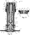
- Figures 12 and 13 show a fourth embodiment of the machining assembly 101 according to the invention, which differs from the embodiment of Figures 11a - 11b in that at the second end 106 of the at least one shaft 102 there is a piston body 130, designed to move said at least one shaft 102 and to slide in said chamber 133 in an integral fashion with said at least one shaft 102, which does not have a channel made in the body.
- Said piston body 130 is in fact sealed and does not put in fluid communication the chamber 133 with the through channel 2.
- a channel 30 in the body of the at least one shaft 102 is formed a channel 30 in the body of the at least one shaft 102 and designed for the passage of said gas, when the chamber 133 is fed pneumatically, fro the chamber 133 to the through channel 2 of said at least one shaft 102 forming a direct fluid connection channel.
- Said machining assembly 101 is therefore configured in such a way that when said chamber 133 is fed pneumatically, said gas acts on said piston body 130, in particular from the relative lower portion, for moving said at least one shaft 102 from said second operating position (shown in Figure 13 ) to said first non-operating position (shown in Figure 12 ), and said gas passes from said chamber 133 to said through channel 2 through said channel 30 formed in the body of the at least one shaft 102.
- the machining assembly 101 has a second inlet 31 of the gas formed at a lower side of the chamber 133, in such a way that when the shaft is in the operating position, the gas is fed pneumatically through said second inlet 31 which acts from below, on the lower portion of the piston body 130 to pass the shaft to the first non-operating position.
- said second inlet 31 is positioned in such a way as to be substantially at the same height as said channel 30 formed in the body of the at least one shaft 102, when the compressed gas is fed from said second inlet 31 when the shaft is in the operating position.
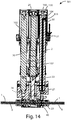
- the embodiment of the machining assembly 101 according to Figure 14 operates in a similar manner to the machining assembly 101 of Figure 12 - 13 , however only one shaft 102 has the through channel 2, whilst in the tool-holder head 21 is formed a further channel 40 which is able to put in fluid connection said through channels 6 in said two tools 1, in such a way that the compressed gas passing through the through channel 2 of a shaft 102 flows out from both the tools 1 simultaneously, using a single compressed gas inlet 31.
Landscapes
- Engineering & Computer Science (AREA)
- Mechanical Engineering (AREA)
- Life Sciences & Earth Sciences (AREA)
- Wood Science & Technology (AREA)
- Forests & Forestry (AREA)
- Cutting Tools, Boring Holders, And Turrets (AREA)
- Electrolytic Production Of Metals (AREA)
- Paper (AREA)
Applications Claiming Priority (1)
| Application Number | Priority Date | Filing Date | Title |
|---|---|---|---|
| IT102018000007340A IT201800007340A1 (it) | 2018-07-19 | 2018-07-19 | Gruppo operatore per la lavorazione di un pannello ed il relativo metodo di lavorazione. |
Publications (2)
| Publication Number | Publication Date |
|---|---|
| EP3597360A1 true EP3597360A1 (fr) | 2020-01-22 |
| EP3597360B1 EP3597360B1 (fr) | 2022-03-16 |
Family
ID=63762904
Family Applications (1)
| Application Number | Title | Priority Date | Filing Date |
|---|---|---|---|
| EP19187402.3A Active EP3597360B1 (fr) | 2018-07-19 | 2019-07-19 | Ensemble d'usinage pour traiter un panneau |
Country Status (2)
| Country | Link |
|---|---|
| EP (1) | EP3597360B1 (fr) |
| IT (1) | IT201800007340A1 (fr) |
Cited By (1)
| Publication number | Priority date | Publication date | Assignee | Title |
|---|---|---|---|---|
| IT202100028367A1 (it) * | 2021-11-08 | 2023-05-08 | Scm Group Spa | Unità di lavorazione perfezionata |
Citations (8)
| Publication number | Priority date | Publication date | Assignee | Title |
|---|---|---|---|---|
| US3502124A (en) * | 1967-10-02 | 1970-03-24 | Milton H Mater | Pole boring machine |
| US5238336A (en) * | 1992-09-29 | 1993-08-24 | Sanders Thomas A | Hand held power dowel tool |
| FR2865678A1 (fr) * | 2004-02-02 | 2005-08-05 | Boucher Freres | Porte-outil pour machine a bois de type mortaiseuse ou similaire |
| DE102008029774A1 (de) * | 2007-06-26 | 2009-02-12 | Hsd S.P.A. | Maschine zum Bearbeiten von Elementen aus Holz oder dergleichen |
| WO2009100708A2 (fr) | 2008-02-12 | 2009-08-20 | Gerhard Koch Maschinenfabrik Gmbh & Co. Kg | Procédé et dispositif pour l'usinage de pièces par enlèvement de copeaux |
| CN201405404Y (zh) | 2009-04-29 | 2010-02-17 | 上海舒平精工机械有限公司 | 木工钻孔装置 |
| CN201405423Y (zh) * | 2009-05-14 | 2010-02-17 | 杨岚 | 防止钻头脱落的保护装置 |
| DE102010028241A1 (de) * | 2010-04-27 | 2011-10-27 | Robert Bosch Gmbh | Minimalmengenschmiersystem |
-
2018
- 2018-07-19 IT IT102018000007340A patent/IT201800007340A1/it unknown
-
2019
- 2019-07-19 EP EP19187402.3A patent/EP3597360B1/fr active Active
Patent Citations (8)
| Publication number | Priority date | Publication date | Assignee | Title |
|---|---|---|---|---|
| US3502124A (en) * | 1967-10-02 | 1970-03-24 | Milton H Mater | Pole boring machine |
| US5238336A (en) * | 1992-09-29 | 1993-08-24 | Sanders Thomas A | Hand held power dowel tool |
| FR2865678A1 (fr) * | 2004-02-02 | 2005-08-05 | Boucher Freres | Porte-outil pour machine a bois de type mortaiseuse ou similaire |
| DE102008029774A1 (de) * | 2007-06-26 | 2009-02-12 | Hsd S.P.A. | Maschine zum Bearbeiten von Elementen aus Holz oder dergleichen |
| WO2009100708A2 (fr) | 2008-02-12 | 2009-08-20 | Gerhard Koch Maschinenfabrik Gmbh & Co. Kg | Procédé et dispositif pour l'usinage de pièces par enlèvement de copeaux |
| CN201405404Y (zh) | 2009-04-29 | 2010-02-17 | 上海舒平精工机械有限公司 | 木工钻孔装置 |
| CN201405423Y (zh) * | 2009-05-14 | 2010-02-17 | 杨岚 | 防止钻头脱落的保护装置 |
| DE102010028241A1 (de) * | 2010-04-27 | 2011-10-27 | Robert Bosch Gmbh | Minimalmengenschmiersystem |
Cited By (2)
| Publication number | Priority date | Publication date | Assignee | Title |
|---|---|---|---|---|
| IT202100028367A1 (it) * | 2021-11-08 | 2023-05-08 | Scm Group Spa | Unità di lavorazione perfezionata |
| EP4177005A3 (fr) * | 2021-11-08 | 2023-07-12 | SCM Group S.p.A. | Unite d'usinage amelioree |
Also Published As
| Publication number | Publication date |
|---|---|
| EP3597360B1 (fr) | 2022-03-16 |
| IT201800007340A1 (it) | 2020-01-19 |
Similar Documents
| Publication | Publication Date | Title |
|---|---|---|
| US4037982A (en) | Machine tools | |
| EP3597360B1 (fr) | Ensemble d'usinage pour traiter un panneau | |
| CN103429373A (zh) | 具有用于将刀具流体冲洗在刀片上的喷嘴的、用于内部切屑切削加工的装置 | |
| CN103846471A (zh) | 便携式穿孔装置用的夹紧装置及带便携式夹紧装置的气动钻头装置 | |
| KR20050010079A (ko) | 파이프의 분기공 천공기기 | |
| JP7065496B2 (ja) | 比較的剛性の高い材料を加工する機械 | |
| EP3466576B1 (fr) | Machine de perçage automatique permettant de percer en une fois au moins deux orifices d'une structure de traverse | |
| JP6017898B2 (ja) | クランプ装置 | |
| KR20130048697A (ko) | 천공 장치의 클램핑 장치 및 에어 구동 드릴 장치 | |
| US20220097117A1 (en) | Sheet metal working machine | |
| CN111183021B (zh) | 机床 | |
| MXPA00011065A (es) | Mecanismo automatizado de perforacion con formacion de collar. | |
| EP1872919B1 (fr) | Centre d'usinage pour usiner des panneaux en bois ou similaire | |
| KR20210047310A (ko) | 작업편을 가공하기 위한 장치 | |
| EP1195207B1 (fr) | Poinçonneuse à tourelles révolver | |
| JPS6036887B2 (ja) | センタ−ボ−ル盤 | |
| EP3892428A1 (fr) | Systèmes et procédés de formation de trous coniques dans des pièces | |
| JP2013094933A (ja) | 工作機械のワークの機内搬送装置 | |
| US6270084B1 (en) | Pneumatic chuck assembly | |
| CA2996026A1 (fr) | Manche de chalumeau comprenant une machoire a commande pneumatique | |
| KR20210149174A (ko) | 고압유체 토출장치 | |
| KR20170090990A (ko) | 카운터싱크 장치 및 이와 관련된 방법 | |
| KR100611361B1 (ko) | 파이프 벤딩 머신의 가동형 롤러 홀더 슬라이더의 선형구동용 유압회로 | |
| EP1308635B1 (fr) | Amélioration dans un distributeur à tiroir dans un circuit hydraulique pour contrôler le mouvement du marteau dans une machine à perforer | |
| US12070824B2 (en) | Systems and methods for removing foreign object debris during a manufacturing process |
Legal Events
| Date | Code | Title | Description |
|---|---|---|---|
| PUAI | Public reference made under article 153(3) epc to a published international application that has entered the european phase |
Free format text: ORIGINAL CODE: 0009012 |
|
| STAA | Information on the status of an ep patent application or granted ep patent |
Free format text: STATUS: THE APPLICATION HAS BEEN PUBLISHED |
|
| AK | Designated contracting states |
Kind code of ref document: A1 Designated state(s): AL AT BE BG CH CY CZ DE DK EE ES FI FR GB GR HR HU IE IS IT LI LT LU LV MC MK MT NL NO PL PT RO RS SE SI SK SM TR |
|
| AX | Request for extension of the european patent |
Extension state: BA ME |
|
| STAA | Information on the status of an ep patent application or granted ep patent |
Free format text: STATUS: REQUEST FOR EXAMINATION WAS MADE |
|
| 17P | Request for examination filed |
Effective date: 20200722 |
|
| RBV | Designated contracting states (corrected) |
Designated state(s): AL AT BE BG CH CY CZ DE DK EE ES FI FR GB GR HR HU IE IS IT LI LT LU LV MC MK MT NL NO PL PT RO RS SE SI SK SM TR |
|
| GRAP | Despatch of communication of intention to grant a patent |
Free format text: ORIGINAL CODE: EPIDOSNIGR1 |
|
| STAA | Information on the status of an ep patent application or granted ep patent |
Free format text: STATUS: GRANT OF PATENT IS INTENDED |
|
| INTG | Intention to grant announced |
Effective date: 20211109 |
|
| GRAS | Grant fee paid |
Free format text: ORIGINAL CODE: EPIDOSNIGR3 |
|
| GRAA | (expected) grant |
Free format text: ORIGINAL CODE: 0009210 |
|
| STAA | Information on the status of an ep patent application or granted ep patent |
Free format text: STATUS: THE PATENT HAS BEEN GRANTED |
|
| AK | Designated contracting states |
Kind code of ref document: B1 Designated state(s): AL AT BE BG CH CY CZ DE DK EE ES FI FR GB GR HR HU IE IS IT LI LT LU LV MC MK MT NL NO PL PT RO RS SE SI SK SM TR |
|
| REG | Reference to a national code |
Ref country code: GB Ref legal event code: FG4D |
|
| REG | Reference to a national code |
Ref country code: CH Ref legal event code: EP Ref country code: DE Ref legal event code: R096 Ref document number: 602019012529 Country of ref document: DE |
|
| REG | Reference to a national code |
Ref country code: IE Ref legal event code: FG4D |
|
| REG | Reference to a national code |
Ref country code: AT Ref legal event code: REF Ref document number: 1475544 Country of ref document: AT Kind code of ref document: T Effective date: 20220415 |
|
| REG | Reference to a national code |
Ref country code: LT Ref legal event code: MG9D |
|
| REG | Reference to a national code |
Ref country code: NL Ref legal event code: MP Effective date: 20220316 |
|
| PG25 | Lapsed in a contracting state [announced via postgrant information from national office to epo] |
Ref country code: SE Free format text: LAPSE BECAUSE OF FAILURE TO SUBMIT A TRANSLATION OF THE DESCRIPTION OR TO PAY THE FEE WITHIN THE PRESCRIBED TIME-LIMIT Effective date: 20220316 Ref country code: RS Free format text: LAPSE BECAUSE OF FAILURE TO SUBMIT A TRANSLATION OF THE DESCRIPTION OR TO PAY THE FEE WITHIN THE PRESCRIBED TIME-LIMIT Effective date: 20220316 Ref country code: NO Free format text: LAPSE BECAUSE OF FAILURE TO SUBMIT A TRANSLATION OF THE DESCRIPTION OR TO PAY THE FEE WITHIN THE PRESCRIBED TIME-LIMIT Effective date: 20220616 Ref country code: LT Free format text: LAPSE BECAUSE OF FAILURE TO SUBMIT A TRANSLATION OF THE DESCRIPTION OR TO PAY THE FEE WITHIN THE PRESCRIBED TIME-LIMIT Effective date: 20220316 Ref country code: HR Free format text: LAPSE BECAUSE OF FAILURE TO SUBMIT A TRANSLATION OF THE DESCRIPTION OR TO PAY THE FEE WITHIN THE PRESCRIBED TIME-LIMIT Effective date: 20220316 Ref country code: BG Free format text: LAPSE BECAUSE OF FAILURE TO SUBMIT A TRANSLATION OF THE DESCRIPTION OR TO PAY THE FEE WITHIN THE PRESCRIBED TIME-LIMIT Effective date: 20220616 |
|
| PG25 | Lapsed in a contracting state [announced via postgrant information from national office to epo] |
Ref country code: LV Free format text: LAPSE BECAUSE OF FAILURE TO SUBMIT A TRANSLATION OF THE DESCRIPTION OR TO PAY THE FEE WITHIN THE PRESCRIBED TIME-LIMIT Effective date: 20220316 Ref country code: GR Free format text: LAPSE BECAUSE OF FAILURE TO SUBMIT A TRANSLATION OF THE DESCRIPTION OR TO PAY THE FEE WITHIN THE PRESCRIBED TIME-LIMIT Effective date: 20220617 Ref country code: FI Free format text: LAPSE BECAUSE OF FAILURE TO SUBMIT A TRANSLATION OF THE DESCRIPTION OR TO PAY THE FEE WITHIN THE PRESCRIBED TIME-LIMIT Effective date: 20220316 |
|
| PG25 | Lapsed in a contracting state [announced via postgrant information from national office to epo] |
Ref country code: NL Free format text: LAPSE BECAUSE OF FAILURE TO SUBMIT A TRANSLATION OF THE DESCRIPTION OR TO PAY THE FEE WITHIN THE PRESCRIBED TIME-LIMIT Effective date: 20220316 |
|
| PG25 | Lapsed in a contracting state [announced via postgrant information from national office to epo] |
Ref country code: SM Free format text: LAPSE BECAUSE OF FAILURE TO SUBMIT A TRANSLATION OF THE DESCRIPTION OR TO PAY THE FEE WITHIN THE PRESCRIBED TIME-LIMIT Effective date: 20220316 Ref country code: SK Free format text: LAPSE BECAUSE OF FAILURE TO SUBMIT A TRANSLATION OF THE DESCRIPTION OR TO PAY THE FEE WITHIN THE PRESCRIBED TIME-LIMIT Effective date: 20220316 Ref country code: RO Free format text: LAPSE BECAUSE OF FAILURE TO SUBMIT A TRANSLATION OF THE DESCRIPTION OR TO PAY THE FEE WITHIN THE PRESCRIBED TIME-LIMIT Effective date: 20220316 Ref country code: PT Free format text: LAPSE BECAUSE OF FAILURE TO SUBMIT A TRANSLATION OF THE DESCRIPTION OR TO PAY THE FEE WITHIN THE PRESCRIBED TIME-LIMIT Effective date: 20220718 Ref country code: ES Free format text: LAPSE BECAUSE OF FAILURE TO SUBMIT A TRANSLATION OF THE DESCRIPTION OR TO PAY THE FEE WITHIN THE PRESCRIBED TIME-LIMIT Effective date: 20220316 Ref country code: EE Free format text: LAPSE BECAUSE OF FAILURE TO SUBMIT A TRANSLATION OF THE DESCRIPTION OR TO PAY THE FEE WITHIN THE PRESCRIBED TIME-LIMIT Effective date: 20220316 Ref country code: CZ Free format text: LAPSE BECAUSE OF FAILURE TO SUBMIT A TRANSLATION OF THE DESCRIPTION OR TO PAY THE FEE WITHIN THE PRESCRIBED TIME-LIMIT Effective date: 20220316 |
|
| PG25 | Lapsed in a contracting state [announced via postgrant information from national office to epo] |
Ref country code: PL Free format text: LAPSE BECAUSE OF FAILURE TO SUBMIT A TRANSLATION OF THE DESCRIPTION OR TO PAY THE FEE WITHIN THE PRESCRIBED TIME-LIMIT Effective date: 20220316 Ref country code: IS Free format text: LAPSE BECAUSE OF FAILURE TO SUBMIT A TRANSLATION OF THE DESCRIPTION OR TO PAY THE FEE WITHIN THE PRESCRIBED TIME-LIMIT Effective date: 20220716 Ref country code: AL Free format text: LAPSE BECAUSE OF FAILURE TO SUBMIT A TRANSLATION OF THE DESCRIPTION OR TO PAY THE FEE WITHIN THE PRESCRIBED TIME-LIMIT Effective date: 20220316 |
|
| REG | Reference to a national code |
Ref country code: DE Ref legal event code: R097 Ref document number: 602019012529 Country of ref document: DE |
|
| PLBE | No opposition filed within time limit |
Free format text: ORIGINAL CODE: 0009261 |
|
| STAA | Information on the status of an ep patent application or granted ep patent |
Free format text: STATUS: NO OPPOSITION FILED WITHIN TIME LIMIT |
|
| PG25 | Lapsed in a contracting state [announced via postgrant information from national office to epo] |
Ref country code: DK Free format text: LAPSE BECAUSE OF FAILURE TO SUBMIT A TRANSLATION OF THE DESCRIPTION OR TO PAY THE FEE WITHIN THE PRESCRIBED TIME-LIMIT Effective date: 20220316 |
|
| 26N | No opposition filed |
Effective date: 20221219 |
|
| PG25 | Lapsed in a contracting state [announced via postgrant information from national office to epo] |
Ref country code: SI Free format text: LAPSE BECAUSE OF FAILURE TO SUBMIT A TRANSLATION OF THE DESCRIPTION OR TO PAY THE FEE WITHIN THE PRESCRIBED TIME-LIMIT Effective date: 20220316 Ref country code: MC Free format text: LAPSE BECAUSE OF FAILURE TO SUBMIT A TRANSLATION OF THE DESCRIPTION OR TO PAY THE FEE WITHIN THE PRESCRIBED TIME-LIMIT Effective date: 20220316 |
|
| REG | Reference to a national code |
Ref country code: CH Ref legal event code: PL |
|
| REG | Reference to a national code |
Ref country code: BE Ref legal event code: MM Effective date: 20220731 |
|
| PG25 | Lapsed in a contracting state [announced via postgrant information from national office to epo] |
Ref country code: LU Free format text: LAPSE BECAUSE OF NON-PAYMENT OF DUE FEES Effective date: 20220719 Ref country code: LI Free format text: LAPSE BECAUSE OF NON-PAYMENT OF DUE FEES Effective date: 20220731 Ref country code: FR Free format text: LAPSE BECAUSE OF NON-PAYMENT OF DUE FEES Effective date: 20220731 Ref country code: CH Free format text: LAPSE BECAUSE OF NON-PAYMENT OF DUE FEES Effective date: 20220731 |
|
| PG25 | Lapsed in a contracting state [announced via postgrant information from national office to epo] |
Ref country code: BE Free format text: LAPSE BECAUSE OF NON-PAYMENT OF DUE FEES Effective date: 20220731 |
|
| P01 | Opt-out of the competence of the unified patent court (upc) registered |
Effective date: 20230518 |
|
| PG25 | Lapsed in a contracting state [announced via postgrant information from national office to epo] |
Ref country code: IE Free format text: LAPSE BECAUSE OF NON-PAYMENT OF DUE FEES Effective date: 20220719 |
|
| REG | Reference to a national code |
Ref country code: AT Ref legal event code: UEP Ref document number: 1475544 Country of ref document: AT Kind code of ref document: T Effective date: 20220316 |
|
| GBPC | Gb: european patent ceased through non-payment of renewal fee |
Effective date: 20230719 |
|
| PG25 | Lapsed in a contracting state [announced via postgrant information from national office to epo] |
Ref country code: HU Free format text: LAPSE BECAUSE OF FAILURE TO SUBMIT A TRANSLATION OF THE DESCRIPTION OR TO PAY THE FEE WITHIN THE PRESCRIBED TIME-LIMIT; INVALID AB INITIO Effective date: 20190719 |
|
| PG25 | Lapsed in a contracting state [announced via postgrant information from national office to epo] |
Ref country code: MK Free format text: LAPSE BECAUSE OF FAILURE TO SUBMIT A TRANSLATION OF THE DESCRIPTION OR TO PAY THE FEE WITHIN THE PRESCRIBED TIME-LIMIT Effective date: 20220316 Ref country code: CY Free format text: LAPSE BECAUSE OF FAILURE TO SUBMIT A TRANSLATION OF THE DESCRIPTION OR TO PAY THE FEE WITHIN THE PRESCRIBED TIME-LIMIT Effective date: 20220316 Ref country code: GB Free format text: LAPSE BECAUSE OF NON-PAYMENT OF DUE FEES Effective date: 20230719 |
|
| PG25 | Lapsed in a contracting state [announced via postgrant information from national office to epo] |
Ref country code: TR Free format text: LAPSE BECAUSE OF FAILURE TO SUBMIT A TRANSLATION OF THE DESCRIPTION OR TO PAY THE FEE WITHIN THE PRESCRIBED TIME-LIMIT Effective date: 20220316 |
|
| PG25 | Lapsed in a contracting state [announced via postgrant information from national office to epo] |
Ref country code: MT Free format text: LAPSE BECAUSE OF FAILURE TO SUBMIT A TRANSLATION OF THE DESCRIPTION OR TO PAY THE FEE WITHIN THE PRESCRIBED TIME-LIMIT Effective date: 20220316 |
|
| PGFP | Annual fee paid to national office [announced via postgrant information from national office to epo] |
Ref country code: DE Payment date: 20250722 Year of fee payment: 7 |
|
| PGFP | Annual fee paid to national office [announced via postgrant information from national office to epo] |
Ref country code: IT Payment date: 20250708 Year of fee payment: 7 |
|
| PGFP | Annual fee paid to national office [announced via postgrant information from national office to epo] |
Ref country code: AT Payment date: 20250721 Year of fee payment: 7 |