EP3599059A1 - Outil de travail à main et procédé de montage d'un élément anti-vibratoire d'un outil de travail à main - Google Patents
Outil de travail à main et procédé de montage d'un élément anti-vibratoire d'un outil de travail à main Download PDFInfo
- Publication number
- EP3599059A1 EP3599059A1 EP18185518.0A EP18185518A EP3599059A1 EP 3599059 A1 EP3599059 A1 EP 3599059A1 EP 18185518 A EP18185518 A EP 18185518A EP 3599059 A1 EP3599059 A1 EP 3599059A1
- Authority
- EP
- European Patent Office
- Prior art keywords
- assembly
- fastening
- fastening screw
- hand
- coil spring
- Prior art date
- Legal status (The legal status is an assumption and is not a legal conclusion. Google has not performed a legal analysis and makes no representation as to the accuracy of the status listed.)
- Granted
Links
Images


Classifications
-
- B—PERFORMING OPERATIONS; TRANSPORTING
- B25—HAND TOOLS; PORTABLE POWER-DRIVEN TOOLS; MANIPULATORS
- B25F—COMBINATION OR MULTI-PURPOSE TOOLS NOT OTHERWISE PROVIDED FOR; DETAILS OR COMPONENTS OF PORTABLE POWER-DRIVEN TOOLS NOT PARTICULARLY RELATED TO THE OPERATIONS PERFORMED AND NOT OTHERWISE PROVIDED FOR
- B25F5/00—Details or components of portable power-driven tools not particularly related to the operations performed and not otherwise provided for
- B25F5/006—Vibration damping means
-
- B—PERFORMING OPERATIONS; TRANSPORTING
- B25—HAND TOOLS; PORTABLE POWER-DRIVEN TOOLS; MANIPULATORS
- B25B—TOOLS OR BENCH DEVICES NOT OTHERWISE PROVIDED FOR, FOR FASTENING, CONNECTING, DISENGAGING, OR HOLDING
- B25B27/00—Hand tools, specially adapted for fitting together or separating parts or objects whether or not involving some deformation, not otherwise provided for
- B25B27/14—Hand tools, specially adapted for fitting together or separating parts or objects whether or not involving some deformation, not otherwise provided for for assembling objects other than by press fit or detaching same
- B25B27/30—Hand tools, specially adapted for fitting together or separating parts or objects whether or not involving some deformation, not otherwise provided for for assembling objects other than by press fit or detaching same positioning or withdrawing springs, e.g. coil or leaf springs
-
- B—PERFORMING OPERATIONS; TRANSPORTING
- B27—WORKING OR PRESERVING WOOD OR SIMILAR MATERIAL; NAILING OR STAPLING MACHINES IN GENERAL
- B27G—ACCESSORY MACHINES OR APPARATUS FOR WORKING WOOD OR SIMILAR MATERIALS; TOOLS FOR WORKING WOOD OR SIMILAR MATERIALS; SAFETY DEVICES FOR WOOD WORKING MACHINES OR TOOLS
- B27G19/00—Safety guards or devices specially adapted for wood saws; Auxiliary devices facilitating proper operation of wood saws
- B27G19/003—Safety guards or devices specially adapted for wood saws; Auxiliary devices facilitating proper operation of wood saws for chain saws
-
- F—MECHANICAL ENGINEERING; LIGHTING; HEATING; WEAPONS; BLASTING
- F16—ENGINEERING ELEMENTS AND UNITS; GENERAL MEASURES FOR PRODUCING AND MAINTAINING EFFECTIVE FUNCTIONING OF MACHINES OR INSTALLATIONS; THERMAL INSULATION IN GENERAL
- F16F—SPRINGS; SHOCK-ABSORBERS; MEANS FOR DAMPING VIBRATION
- F16F1/00—Springs
- F16F1/02—Springs made of steel or other material having low internal friction; Wound, torsion, leaf, cup, ring or the like springs, the material of the spring not being relevant
- F16F1/04—Wound springs
- F16F1/12—Attachments or mountings
- F16F1/125—Attachments or mountings where the end coils of the spring engage an axial insert
-
- F—MECHANICAL ENGINEERING; LIGHTING; HEATING; WEAPONS; BLASTING
- F16—ENGINEERING ELEMENTS AND UNITS; GENERAL MEASURES FOR PRODUCING AND MAINTAINING EFFECTIVE FUNCTIONING OF MACHINES OR INSTALLATIONS; THERMAL INSULATION IN GENERAL
- F16F—SPRINGS; SHOCK-ABSORBERS; MEANS FOR DAMPING VIBRATION
- F16F15/00—Suppression of vibrations in systems; Means or arrangements for avoiding or reducing out-of-balance forces, e.g. due to motion
- F16F15/02—Suppression of vibrations of non-rotating, e.g. reciprocating systems; Suppression of vibrations of rotating systems by use of members not moving with the rotating systems
- F16F15/04—Suppression of vibrations of non-rotating, e.g. reciprocating systems; Suppression of vibrations of rotating systems by use of members not moving with the rotating systems using elastic means
-
- F—MECHANICAL ENGINEERING; LIGHTING; HEATING; WEAPONS; BLASTING
- F16—ENGINEERING ELEMENTS AND UNITS; GENERAL MEASURES FOR PRODUCING AND MAINTAINING EFFECTIVE FUNCTIONING OF MACHINES OR INSTALLATIONS; THERMAL INSULATION IN GENERAL
- F16F—SPRINGS; SHOCK-ABSORBERS; MEANS FOR DAMPING VIBRATION
- F16F15/00—Suppression of vibrations in systems; Means or arrangements for avoiding or reducing out-of-balance forces, e.g. due to motion
- F16F15/02—Suppression of vibrations of non-rotating, e.g. reciprocating systems; Suppression of vibrations of rotating systems by use of members not moving with the rotating systems
- F16F15/04—Suppression of vibrations of non-rotating, e.g. reciprocating systems; Suppression of vibrations of rotating systems by use of members not moving with the rotating systems using elastic means
- F16F15/06—Suppression of vibrations of non-rotating, e.g. reciprocating systems; Suppression of vibrations of rotating systems by use of members not moving with the rotating systems using elastic means with metal springs
- F16F15/067—Suppression of vibrations of non-rotating, e.g. reciprocating systems; Suppression of vibrations of rotating systems by use of members not moving with the rotating systems using elastic means with metal springs using only wound springs
-
- A—HUMAN NECESSITIES
- A01—AGRICULTURE; FORESTRY; ANIMAL HUSBANDRY; HUNTING; TRAPPING; FISHING
- A01G—HORTICULTURE; CULTIVATION OF VEGETABLES, FLOWERS, RICE, FRUIT, VINES, HOPS OR SEAWEED; FORESTRY; WATERING
- A01G3/00—Cutting implements specially adapted for horticultural purposes; Delimbing standing trees
- A01G3/08—Other tools for pruning, branching or delimbing standing trees
- A01G3/085—Motor-driven saws for pruning or branching
- A01G3/086—Chain saws
-
- B—PERFORMING OPERATIONS; TRANSPORTING
- B27—WORKING OR PRESERVING WOOD OR SIMILAR MATERIAL; NAILING OR STAPLING MACHINES IN GENERAL
- B27B—SAWS FOR WOOD OR SIMILAR MATERIAL; COMPONENTS OR ACCESSORIES THEREFOR
- B27B17/00—Chain saws; Equipment therefor
- B27B17/0008—Means for carrying the chain saw, e.g. handles
-
- B—PERFORMING OPERATIONS; TRANSPORTING
- B27—WORKING OR PRESERVING WOOD OR SIMILAR MATERIAL; NAILING OR STAPLING MACHINES IN GENERAL
- B27B—SAWS FOR WOOD OR SIMILAR MATERIAL; COMPONENTS OR ACCESSORIES THEREFOR
- B27B17/00—Chain saws; Equipment therefor
- B27B17/0033—Devices for attenuation of vibrations
Definitions
- the invention relates to a hand-held implement of the type specified in the preamble of claim 1 and a method for mounting an anti-vibration element of a hand-held implement.
- JP 2006-042724 A is a hand-held tool, namely a hedge trimmer known that has a drive motor and a handle unit.
- the drive motor is vibration-decoupled from the handle unit via anti-vibration elements.
- the anti-vibration elements have coil springs, each of which is fixed to the motor unit by means of a screw.
- the other end of the coil spring is screwed into a socket connected to the handle assembly.
- the fastening screw for fixing the coil spring to the motor assembly is accessible through an opening. Through this opening, the screw can also be pushed into the coil spring for assembly.
- the invention has for its object to provide a hand-held implement of the generic type that allows simple assembly with a simple structure. Another object of the invention is to provide a method for mounting an anti-vibration element of a hand-held implement.
- the head of the fastening screw of the coil spring has an engagement contour for a tool.
- the engagement contour is accessible through an opening in a connecting piece of the second assembly. It is envisaged that the inside diameter of the opening is smaller than the outside diameter of the head of the fastening screw.
- the fastening screw can no longer fall out of the interior of the coil spring as soon as the second end of the coil spring is screwed onto the connecting piece.
- the fastening screw Before the coil spring is mounted on the connecting piece, the fastening screw can be arranged and positioned inside the coil spring. After screwing on the connector, the fastening screw is already pre-positioned and only needs to be fixed on the first assembly. This simplifies the assembly of the anti-vibration element of the implement. For the assembly of the anti-vibration element, advantageously only two screwing operations, namely screwing on the second end of the coil spring on the connecting piece and screwing in the fastening screw on the first assembly, are required. Further screwing operations are not necessary.
- the fastening screw with the coil spring can be preassembled on the second assembly and can only be fixed to the first assembly at a later time.
- the fastening screw with the coil spring can be preassembled on the second assembly and can only be fixed to the first assembly at a later time.
- there may be further assembly steps for assembling the working device during which the second assembly can be positioned and rotated as desired without the fastening screw being removed from the helical spring can fall out.
- the assembly of the implement is significantly simplified and can be carried out more flexibly.
- engagement contour denotes the area of the fastening screw on which a tool and the screw are in engagement with one another.
- the fastening contour is preferably an internal hexagon, a slot, a cross slot or a Torx.
- the engagement contour can also be designed differently and, for example, also be provided on the outer circumference of the head of the fastening screw.
- the one of the two assemblies advantageously comprises at least one handle, and the other of the two assemblies comprises a drive motor.
- the nozzle is preferably formed in one piece with a housing part of the second assembly.
- the term “housing part” is to be understood broadly and can also denote, for example, a frame or the like.
- the connecting piece can also be formed in one piece with a component, in particular a housing part of the first assembly.
- a further assembly step, with which the connection piece must be fixed to a housing part of the first or second assembly, can be omitted.
- the housing part with which the nozzle is formed in one piece forms in particular at least one handle.
- the housing part is preferably a handle housing which forms one or more handles of the implement and on which the connecting piece is formed in one piece.
- the handle housing can in particular be designed as a handle frame.
- the first assembly advantageously has an anti-twist device which secures the fastening eye of the coil spring against rotation about the longitudinal central axis of the coil spring. This ensures that the coil spring does not rotate with respect to the second assembly when the fastening screw is tightened. Depending on the winding direction of the spring, partial unscrewing of the connecting piece or tensioning of the spring can thereby be avoided.
- a simple design of the anti-rotation device is achieved if the fastening eyelet has a non-circular outer contour and the first assembly against the non-circular outer contour Twisting around the longitudinal central axis of the coil spring secures.
- the fastening eyelet particularly preferably has an area in which the distance of the wire of the helical spring from the longitudinal central axis of the helical spring increases in the direction of the end of the winding wire.
- the fastening eyelet is advantageously at least partially arranged in a recess in the first assembly. This facilitates the positioning of the fastening eyelet on the first assembly during assembly. It is particularly preferred that at least one wall delimiting the depression forms an anti-rotation device for the fastening eye against rotation about the longitudinal central axis of the helical spring. As a result, no additional components or elements are required to form the anti-rotation device.
- the fastening eye preferably forms a flat support surface for support on the assembly.
- the section of the coil wire of the helical spring, which forms the fastening eyelet, is particularly preferably wound at the end of the helical spring in a plane running perpendicular to the longitudinal center axis and thereby forms the flat contact surface.
- the helical spring can also be ground in the area of the fastening eye.
- the inner diameter of the fastening eye is advantageously smaller than the outer diameter of the head of the fastening screw.
- the fastening screw cannot pass through the fastening eyelet from inside the coil spring.
- the socket protrudes into the inside of the coil spring. This results in a reduced space requirement compared to a nozzle arranged on the outer circumference of the helical spring.
- the connector can also be arranged on the outer circumference of the coil spring, and the coil spring can be screwed into an internal thread of the connector.
- the nozzle preferably has an end face arranged inside the helical spring.
- the distance between the fastening eyelet and the face of the socket is in unloaded state of the implement is preferably smaller than the length of the fastening screw.
- the end of the fastening screw is secured in the fastening eyelet, so that the position of the fastening screw is predetermined. This simplifies assembly.
- the distance between a support surface of the fastening eyelet, which is provided for contact with the first assembly, and the end face of the connecting piece is advantageously less than the length of the fastening screw. As a result, the free end of the fastening screw lies inside the fastening eyelet when the head rests on the end face of the connecting piece.
- the connector advantageously has a threaded section on which the coil spring is held.
- the threaded section has in particular a groove into which the helical spring is screwed.
- the connector advantageously has a sleeve section which is at a distance from the helical spring in the radial direction.
- the end face of the connecting piece is advantageously formed on the sleeve section.
- the implement preferably has at least two anti-vibration elements with a helical spring. It is provided that all the connecting pieces of the at least two anti-vibration elements, on each of which a second end of the coil springs is screwed in, are arranged on the second assembly and that all engagement contours of the fastening screws are accessible from the same side of the implement. Accordingly, all anti-vibration elements with coil springs must be mounted on the same side of the implement. In particular for tightening the fastening screws, no change in the position of the implement is necessary.
- the longitudinal central axes of all helical springs of the implement are preferably approximately parallel. The angular distance between the longitudinal central axes of the coil springs of all anti-vibration elements is advantageously less than 5 °.
- a method for mounting an anti-vibration element of a hand-held implement provides that in a first step the head of the fastening screw is arranged in the coil spring, that in a later, second step the second end of the coil spring is screwed into the socket of the second assembly and that in a later, third step, the fastening screw is screwed into the first assembly.
- further mounting steps for mounting the working device can take place that are independent of the mounting of the anti-vibration element.
- the second assembly step advantageously follows immediately after the first assembly step, so that the fastening screw is secured immediately after being arranged in the coil spring by screwing the coil spring onto the connecting piece in the coil spring.
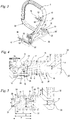
- Fig. 1 shows schematically a hand-held implement 1, in the embodiment a chainsaw.
- the hand-held implement can also be another implement such as, for example, a cut-off machine, a brush cutter, a hedge trimmer, a lawn mower or the like.
- the implement 1 has a drive motor 11 which serves to drive a tool, namely a saw chain 9.
- the saw chain 9 is arranged circumferentially on a guide rail 8.
- Handles 4 and 5 are used to guide the implement 1 during operation.
- the handle 4 is designed as a rear handle and has control elements 6, for example a gas lever and a gas lever lock.
- the handle 5 is designed as a handle tube.
- the implement 1 also has a hand guard 7 which extends between the handle 5 and the guide rail 9. The hand guard 7 can be used to trigger a braking device (not shown) for the saw chain 9.
- a first assembly 31 of the implement 1 comprises the drive motor 11 and the tool, which in the exemplary embodiment is designed as a guide rail 8 with the saw chain 9.
- the handles 4 and 5 are part of a second assembly 32 of the implement.
- the second assembly 32 is a handle housing, on which an operating medium tank 3, in particular a fuel tank, can also be integrated.
- the first assembly 31 includes the operating medium tank 3.
- vibrations arise, in particular by the Tool and / or the drive motor 11.
- an oscillating gap 2 is formed between the assemblies 31 and 32, the relative movements of the first assembly 31 relative to the second assembly 32 permits.
- the vibration gap 32 is bridged by anti-vibration elements 10.
- three anti-vibration elements 10 are shown, the structure of which is described in more detail below.
- further and / or differently constructed anti-vibration elements can be provided.
- the drive motor 11 is an internal combustion engine.
- An air filter 12 is arranged on the second assembly 32, via which combustion air for the drive motor 11 is drawn in.
- the air filter 12 is connected to the drive motor 11 via an intake duct 13.
- the intake duct 13 bridges the oscillating gap 2. Another arrangement of the air filter 12 can also be advantageous.
- Fig. 2 shows a part of the first assembly 31 schematically.
- the first assembly 31 comprises a motor mount 37 on which the drive motor 11 is held. It can be provided that parts of the drive motor 11, for example a crankcase of the drive motor 11, are formed in one piece with the motor mount 37.
- Two anti-vibration elements 10 are held on the motor mount 37.
- a coil spring 15 and a fastening screw 16 of each anti-vibration element 10 are shown. How Fig. 2 shows, the fastening screws each have an engagement contour 17, in the exemplary embodiment a Torx contour for engaging a tool.
- the drive motor 11 has a cylinder 14 on which a third anti-vibration element 10 is held.
- the coil spring 15 and the fastening screw 16 with the engagement contour 17 are also shown of the third anti-vibration element 10.
- the anti-vibration elements 10 have longitudinal central axes 30, which correspond to the central axis of the coil springs 15. How Fig. 2 shows, In the exemplary embodiment, the longitudinal central axes 30 run parallel to one another. The angle between the longitudinal central axes 30 of the anti-vibration elements 10 is advantageously at most 5 °.
- Fig. 3 shows the second assembly 32 with anti-vibration elements 10 arranged thereon in a perspective view.
- the second assembly 32 comprises the handle tube 5 and a connecting section 23 which connects the two ends of the handle tube 5 to one another.
- engagement contours not shown 17 ( Fig. 2 ) of the fastening screws 16 are accessible through openings 22 of the second assembly 32.
- the handle tube 5 is formed in one piece with the connecting section 23.
- the grip tube 5 with the connecting section 23 and the connecting piece 18 is advantageously produced as a part from plastic in an injection molding process.
- the openings 22 are openings in the one-piece housing part.
- the second assembly 32 advantageously comprises further components, in particular the one shown in FIG Fig. 1 shown handle 4.
- a first end 19 of the coil spring 15 forms a fastening eyelet 21.
- the fastening screw 16 projects through the fastening eyelet 21 with its shaft 39.
- the fastening screw 16 has a head 24 which fixes the fastening eyelet 21 on the first assembly 31 in the assembled state of the arrangement ,
- the fastening eyelet 21 is arranged in the embodiment in a recess 26 of the first assembly 31.
- the longitudinal central axis of the fastening screw 16 extends from the first end 19 to the second end 20 of the helical spring 15 completely within the helical spring 15.
- the longitudinal central axis of the fastening screw 16 coincides with the longitudinal central axis 30 of the helical spring 15.
- the fastening screw 16 and the coil spring 15 are coaxial with each other.
- the longitudinal central axis of the fastening screw 16 runs through the opening 22.
- the engagement contour 17 is formed in the head 24 of the fastening screw 16 on the side facing the socket 18.
- a nozzle 18 for each anti-vibration element 10 is integrally formed on the one-piece housing part.
- An opening 22 projects through the connecting pieces 18.
- the opening 22 has an inner diameter a that is smaller than an outer diameter d of the helical spring 15.
- a second end 20 of the coil spring 15 is screwed onto the socket 18.
- the second end 20 is screwed onto the outer circumference of the connector 18.
- the connector 18 is cup-shaped and the second end 20 of the coil spring 15 is screwed to an inner circumference of the connector 18.
- the head 24 of the fastening screw 16 has an outer diameter b.
- the outer diameter b is significantly larger than the inner diameter a of the opening 22.
- the fastening screw 16 cannot pass through the opening 22.
- the fastening screw 16 cannot be inserted into the coil spring 15 through the opening 22.
- the fastening screw 16 is therefore to be inserted into the helical spring 15 before the helical spring 15 is mounted on the connecting piece 18.
- the fastening screw 16 can then only be actuated through the opening 22 on the engagement contour 17 and thus mounted on the first assembly 31, but cannot fall out of the interior 33 of the coil spring 15 through the opening 22.
- the interior 33 of the coil spring 15 is the space enclosed by the spring turns of the coil spring 15.
- the fastening eyelet 21 has an outer diameter e.
- the outer diameter e is smaller than the diameter d of the coil spring 15 ( Fig. 4 ).
- the outer diameter b of the head 24 of the fastening screw 16 is only slightly larger than the outer diameter e of the fastening eyelet 21.
- the fastening eyelet 21 has a contact surface 25 which is flat. The bearing surface 25 lies in the recess 26 in the assembled state.
- the fastening screw 16 has a length g measured parallel to the longitudinal central axis 30.
- the fastening eyelet 21 has in the shown unloaded state of the working device 1 to an end face 27 of the connector 18 arranged in the interior of the helical spring 15 a distance f.
- the length g is greater than the distance f.
- the distance f is measured at the location of the fastening eye 21 at which the head 24 of the fastening screw 16 comes to rest.
- the unloaded state of the implement 1 is a state in which no forces act on the implement 1 on the handles and on the saw chain and expand or compress the oscillating gap 2.
- the fastening eyelet 21 aligns the end 42 of the fastening screw 16 to open the bore 35 ( Fig. 6 ) of the first assembly 31.
- the bore 35 is designed as a threaded bore into which the fastening screw 16 is screwed in the assembled state. Because the end 42 of the fastening screw 16 is aligned with the bore 35, the fastening screw 16 can be threaded more easily onto the first assembly 31 during assembly. This simplifies assembly.
- the engagement contour 17 has a largest diameter c, which is smaller than the diameter a of the opening 22. As a result, a tool for engagement in the engagement contour 17 can be inserted through the opening 22.
- the inclined position of the fastening screw 16 in the interior 33 of the coil spring 15 is limited to a degree at which an engagement of a tool 34 ( Fig. 9 ) through the opening 22 into the engagement contour 17 of the fastening screw 16 is possible. It may be expedient to make the diameter a of the opening 22 large enough that the tool 34 ( Fig. 9 ) can be arranged obliquely in the opening 22. As a result, the accessibility of the engagement contour 17 of a fastening screw 16 which is inclined to a limited extent can be improved.
- the diameter a of the opening 22 is, however, smaller than the outer diameter b of the head 24 of the fastening screw 16, so that there is preferably an annular contact of the head 24 on the end face 27 of the connector 18.
- the contact surface 25 of the fastening eye 21 is at a distance p from the end face 27 of the connector 18.
- the distance p is greater than the length g of the fastening screw 16.
- the nozzle 18 has a threaded portion 40 and a sleeve portion 41 (see also Fig. 4 ).
- the coil spring 15 bears against the threaded section 40 with its windings.
- the axial length of the threaded section 40 is adapted to the desired suspension properties.
- the sleeve section 41 extends between the threaded section 40 and the end face 27 of the socket 18 radially within the windings of the helical spring 15.
- the axial length of the sleeve section is selected such that the distance p of the bearing surface 25 to the end face 27 increases the end 42 of the fastening screw 16 and the distance f of the fastening eye 21 to the end face 27 is less than the length g of the fastening screw 16.
- the free end 42 lies within the fastening eye 21 when the fastening screw 16 is maximally drawn into the coil spring 15.
- the end 42 of the fastening screw 16 does not protrude beyond the first end 19 of the coil spring 15 when the fastening screw 16 rests with its head 24 on the end face 27 of the connector 18. This is particularly advantageous if the assembly of the first assembly 31 takes place in such a way that the longitudinal central axis 30 of the helical spring 15 is oriented in the direction of gravity and the second assembly 32 is arranged in particular below the first assembly 31. Then the fastening screws 16 automatically assume their maximum retracted position and do not protrude and cannot get caught on the first assembly 31 when the first ends 19 of the coil springs 15 are arranged.
- the connecting piece 18 has a sleeve section 41 in addition to the threaded section 40, the lengths of the sleeve section 41 and of the threaded section 40 can be selected independently of one another to match the length g of the fastening screw 16 and the desired characteristic curve of the coil spring 15.
- Fig. 6 shows the first end 19 of a coil spring 15 which is fixed to the cylinder 14. How Fig. 6 shows, the cylinder 14 has the recess 26. In the recess 26, a threaded bore 35 is arranged. The fastening screw 16 for fastening the coil spring 15 to the cylinder 14 can be screwed into the threaded bore 35.
- the recess 26 has walls 28 and 29 which are arranged on opposite legs 43, 44 of the fastening eye 21.
- the fastening eyelet 21 is supported on one wall 28 or the other wall 29 with its one leg 43 or its other leg 44.
- the walls 28 and 29 advantageously have a slight angular offset to the legs 43, 44 of the fastening eye 21.
- the angular offset serves to compensate for tolerances in the alignment of the fastening eye 21.
- the angular offset that is to say the angle which the legs 43, 44 form with the walls 28, 29, is advantageous on each wall 28, 29 between 5 ° and 15 °. In the in Fig. 7 shown position, the legs 43 and 44 of the fastening eyelet 21 are close to both walls 28 and 29.
- the fastening eyelet 21 does not run in the form of a circular arc over the longitudinal central axis 30 over its entire length.
- the fastening eyelet 21 has an arc section 45 in which it runs around the longitudinal central axis 30 and the adjoining legs 43 and 44, which run approximately tangentially to the longitudinal central axis 30.
- the walls 28, 29 of the recess 26 follow the contour of the fastening eyelet 21 in the region of the curved section 45 and have an angular offset to the walls 28, 29 in the region of the legs 43, 44.
- the winding wire on the fastening eye 21 to the longitudinal central axis 30 increases.
- the winding wire has a smallest distance k from the longitudinal central axis 30.
- the distance increases to a greatest distance i.
- the wall 29 is at a distance m from the longitudinal center axis 30 which is greater than the smallest distance k, but significantly smaller than the distance i.
- the wall 28 is at a distance o from the longitudinal central axis 30 which is less than half the diameter d of the helical spring 15.
- the fastening eye 21 has a smallest inner diameter h.
- the smallest inner diameter h is larger than an outer diameter n of a shaft 39 of the fastening screw 16 ( Fig. 9 ).
- Fig. 9 schematically shows the individual parts of the anti-vibration element 10, via which the first assembly 31 and the second assembly 32 are connected to one another.
- the anti-vibration element 10 has only the coil spring 15 and the individual parts Fastening screw 16.
- the connector 18 of the anti-vibration element 10 is integrally formed on the second assembly 32.
- the connector 18 has in the threaded portion 40 on its outer circumference a groove 36 which is helical and into which the coil spring 15 can be screwed.
- the fastening screw 16 is first arranged in the interior 33 of the helical spring 15, in such a way that the shaft 39 projects through the fastening eye 21.
- the coil spring 15 is then screwed into the groove 36 of the connector 18.
- both the inner diameter h of the fastening eyelet 21 and the inner diameter a of the opening 22 are smaller than the outer diameter b of the head 24 of the fastening screw 16, the fastening screw 16 is thereby held captively on the second assembly 32. Since the distance f is smaller than the length g (see Fig.
- the shaft 39 cannot come loose from the fastening eyelet 21, so that the fastening screw 16 is in the correct position for mounting on the first assembly 31, for example on the cylinder 14 or on the engine mount 37. Since the fastening screw 16 and the coil spring 15 are held on the second assembly 32, further assembly steps that are independent of the anti-vibration elements can be carried out.
- the two assemblies 31 and 32 are connected to one another.
- the fastening eye 21 is arranged in the recess 26 of the cylinder 14, and the fastening screw 16 is screwed into the bore 35 of the first assembly 31.
- a tool 34 is provided, which in Fig. 9 is shown schematically and that can be, for example, a screwdriver.
- the tool 34 is dimensioned such that it passes through the opening 22 into the engagement contour 17 ( Fig. 4 ) can be inserted. Since the inclination of the fastening screw 16 within the helical spring 15 is limited by the fastening eyelet 21, at least part of the engagement contour 17 is always covered with the opening 22 and accessible to a tool 34.
- At least two, advantageously all, anti-vibration elements 10 are preassembled on the same assembly 31, 32, in particular on the same housing part.
- all first ends 19 of the coil springs 15 come "simultaneously" into contact with the associated depressions 26 of the other assembly 31, so that all fastening screws 16 can be screwed in succession or simultaneously in one operation.
Landscapes
- Engineering & Computer Science (AREA)
- Mechanical Engineering (AREA)
- General Engineering & Computer Science (AREA)
- Physics & Mathematics (AREA)
- Acoustics & Sound (AREA)
- Aviation & Aerospace Engineering (AREA)
- Life Sciences & Earth Sciences (AREA)
- Wood Science & Technology (AREA)
- Forests & Forestry (AREA)
- Harvester Elements (AREA)
- Vibration Prevention Devices (AREA)
- Springs (AREA)
Priority Applications (3)
| Application Number | Priority Date | Filing Date | Title |
|---|---|---|---|
| EP18185518.0A EP3599059B1 (fr) | 2018-07-25 | 2018-07-25 | Outil de travail à main et procédé de montage d'un élément anti-vibratoire d'un outil de travail à main |
| US16/513,347 US10807225B2 (en) | 2018-07-25 | 2019-07-16 | Handheld work apparatus and method for mounting an anti-vibration unit thereof |
| CN201910676045.3A CN110774231B (zh) | 2018-07-25 | 2019-07-25 | 手动引导的工作仪器和用于装配手动引导的工作仪器的抗振动元件的方法 |
Applications Claiming Priority (1)
| Application Number | Priority Date | Filing Date | Title |
|---|---|---|---|
| EP18185518.0A EP3599059B1 (fr) | 2018-07-25 | 2018-07-25 | Outil de travail à main et procédé de montage d'un élément anti-vibratoire d'un outil de travail à main |
Publications (2)
| Publication Number | Publication Date |
|---|---|
| EP3599059A1 true EP3599059A1 (fr) | 2020-01-29 |
| EP3599059B1 EP3599059B1 (fr) | 2022-05-04 |
Family
ID=63047230
Family Applications (1)
| Application Number | Title | Priority Date | Filing Date |
|---|---|---|---|
| EP18185518.0A Active EP3599059B1 (fr) | 2018-07-25 | 2018-07-25 | Outil de travail à main et procédé de montage d'un élément anti-vibratoire d'un outil de travail à main |
Country Status (3)
| Country | Link |
|---|---|
| US (1) | US10807225B2 (fr) |
| EP (1) | EP3599059B1 (fr) |
| CN (1) | CN110774231B (fr) |
Cited By (1)
| Publication number | Priority date | Publication date | Assignee | Title |
|---|---|---|---|---|
| WO2024088891A1 (fr) * | 2022-10-25 | 2024-05-02 | Robert Bosch Gmbh | Machine-outil portative et système de machine-outil portative |
Families Citing this family (4)
| Publication number | Priority date | Publication date | Assignee | Title |
|---|---|---|---|---|
| EP3808519A3 (fr) * | 2019-10-18 | 2021-06-30 | Globe (Jiangsu) Co., Ltd. | Scie à chaîne |
| US11577422B2 (en) * | 2020-01-31 | 2023-02-14 | Husqvarna Ab | Display or storage assembly for handheld power tool |
| CN112493006A (zh) * | 2020-11-27 | 2021-03-16 | 浙江中马园林机器股份有限公司 | 一种减振油锯 |
| EP4008491A1 (fr) * | 2020-12-04 | 2022-06-08 | Hilti Aktiengesellschaft | Machine-outil doté d'une première poignée, d'une seconde poignée et d'un corps principal |
Citations (5)
| Publication number | Priority date | Publication date | Assignee | Title |
|---|---|---|---|---|
| JP2002038977A (ja) * | 2000-04-26 | 2002-02-06 | Kaaz Corp | 動力作業機のブレーキ作動装置 |
| US20040016133A1 (en) * | 2002-07-10 | 2004-01-29 | Dolmar Gmbh | Adjustable antivibration system, in particular for a hand-held work machine |
| JP2006042724A (ja) | 2004-08-06 | 2006-02-16 | Ochiai Cutlery Mfg Co Ltd | 動力作業機の防振構造 |
| JP2011177798A (ja) * | 2010-02-26 | 2011-09-15 | Hitachi Koki Co Ltd | エンジン工具 |
| EP2436263A2 (fr) * | 2010-09-29 | 2012-04-04 | Hitachi Koki Co., Ltd. | Machine de travail portable |
Family Cites Families (30)
| Publication number | Priority date | Publication date | Assignee | Title |
|---|---|---|---|---|
| US4141143A (en) * | 1977-10-26 | 1979-02-27 | Mcculloch Corporation | Chain saw handle and vibration isolation system |
| US5090657A (en) * | 1990-08-06 | 1992-02-25 | Tecumseh Products Company | Cable reinforced mounting system |
| SE470418B (sv) * | 1992-07-17 | 1994-02-21 | Electrolux Ab | Avvibreringsanordning |
| JP2598703Y2 (ja) * | 1992-10-14 | 1999-08-16 | 株式会社共立 | 防振用コイルばねの取り付け構造 |
| US5697465A (en) * | 1995-04-10 | 1997-12-16 | Kruse; Thomas E. | Personal mobility vehicle |
| JP4081232B2 (ja) * | 2000-12-15 | 2008-04-23 | 株式会社共立 | 防振装置付きチェーンソー |
| DE10105826B4 (de) * | 2001-02-07 | 2012-05-31 | Andreas Stihl Ag & Co | Schwingungsdämpfer zwischen zwei Bauteilen |
| US6994068B2 (en) * | 2001-04-28 | 2006-02-07 | Andreas Stihl Ag & Co, Kg | Antivibration device |
| US7152853B2 (en) * | 2003-06-07 | 2006-12-26 | Andreas Stihl Ag & Co. Kg | Manually operated implement |
| DE10332637A1 (de) * | 2003-07-18 | 2005-02-03 | Andreas Stihl Ag & Co. Kg | Antivibrationselement |
| JP4194032B2 (ja) | 2003-09-12 | 2008-12-10 | 株式会社共立 | 防振用コイルスプリングホルダー |
| DE102004031866B4 (de) * | 2004-07-01 | 2015-09-10 | Andreas Stihl Ag & Co. Kg | Handgeführtes Arbeitsgerät |
| DE102005047882B4 (de) * | 2005-10-06 | 2017-04-27 | Andreas Stihl Ag & Co. Kg | Handgeführtes Arbeitsgerät |
| DE102007000270A1 (de) * | 2007-05-11 | 2008-11-20 | Hilti Aktiengesellschaft | Vibrierende Handwerkzeugmaschine mit Antivibrationselement |
| DE102007022115B4 (de) * | 2007-05-11 | 2024-11-14 | Andreas Stihl Ag & Co. Kg | Handgeführte Motorsäge |
| DE102007048887B4 (de) * | 2007-10-11 | 2017-10-26 | Andreas Stihl Ag & Co. Kg | Handgeführtes Arbeitsgerät |
| JP2010233472A (ja) | 2009-03-30 | 2010-10-21 | Makita Corp | 手持ち式動力作業機 |
| JP2011182682A (ja) | 2010-03-05 | 2011-09-22 | Hitachi Koki Co Ltd | 作業機械 |
| JP5509984B2 (ja) | 2010-03-26 | 2014-06-04 | 日立工機株式会社 | 作業機械 |
| JP5508097B2 (ja) * | 2010-03-31 | 2014-05-28 | 株式会社マキタ | 手持式作業機の防振装置 |
| DE102011007725A1 (de) * | 2011-04-20 | 2012-10-25 | Hilti Aktiengesellschaft | Handwerkzeugmaschine und Tilger |
| JP2013021979A (ja) | 2011-07-21 | 2013-02-04 | Hitachi Koki Co Ltd | 刈払機 |
| JP2013031931A (ja) | 2011-08-01 | 2013-02-14 | Hitachi Koki Co Ltd | 携帯式作業機 |
| JP2014148005A (ja) | 2013-02-01 | 2014-08-21 | Hitachi Koki Co Ltd | 携帯型作業機 |
| WO2014161048A1 (fr) * | 2013-04-05 | 2014-10-09 | John Arthur Notaras | Souffleur motorisé portable avec système de poignée anti-vibrations et poids fonctionnel réduit |
| JP6070945B2 (ja) * | 2013-05-28 | 2017-02-01 | 日立工機株式会社 | 携帯型作業機 |
| DE102013012511A1 (de) * | 2013-07-27 | 2015-01-29 | Andreas Stihl Ag & Co. Kg | "Handgeführtes Arbeitsgerät" |
| DE102013012513A1 (de) * | 2013-07-27 | 2015-01-29 | Andreas Stihl Ag & Co. Kg | "Handgeführtes Arbeitsgerät" |
| CN204136026U (zh) | 2014-09-23 | 2015-02-04 | 石向红 | 一种减震油锯 |
| EP3058807A1 (fr) * | 2015-02-17 | 2016-08-24 | Andreas Stihl AG & Co. KG | Appareil de travail manuel doté d'une section télescopique |
-
2018
- 2018-07-25 EP EP18185518.0A patent/EP3599059B1/fr active Active
-
2019
- 2019-07-16 US US16/513,347 patent/US10807225B2/en active Active
- 2019-07-25 CN CN201910676045.3A patent/CN110774231B/zh active Active
Patent Citations (5)
| Publication number | Priority date | Publication date | Assignee | Title |
|---|---|---|---|---|
| JP2002038977A (ja) * | 2000-04-26 | 2002-02-06 | Kaaz Corp | 動力作業機のブレーキ作動装置 |
| US20040016133A1 (en) * | 2002-07-10 | 2004-01-29 | Dolmar Gmbh | Adjustable antivibration system, in particular for a hand-held work machine |
| JP2006042724A (ja) | 2004-08-06 | 2006-02-16 | Ochiai Cutlery Mfg Co Ltd | 動力作業機の防振構造 |
| JP2011177798A (ja) * | 2010-02-26 | 2011-09-15 | Hitachi Koki Co Ltd | エンジン工具 |
| EP2436263A2 (fr) * | 2010-09-29 | 2012-04-04 | Hitachi Koki Co., Ltd. | Machine de travail portable |
Cited By (1)
| Publication number | Priority date | Publication date | Assignee | Title |
|---|---|---|---|---|
| WO2024088891A1 (fr) * | 2022-10-25 | 2024-05-02 | Robert Bosch Gmbh | Machine-outil portative et système de machine-outil portative |
Also Published As
| Publication number | Publication date |
|---|---|
| CN110774231B (zh) | 2022-11-01 |
| US20200030959A1 (en) | 2020-01-30 |
| US10807225B2 (en) | 2020-10-20 |
| CN110774231A (zh) | 2020-02-11 |
| EP3599059B1 (fr) | 2022-05-04 |
Similar Documents
| Publication | Publication Date | Title |
|---|---|---|
| EP3599059B1 (fr) | Outil de travail à main et procédé de montage d'un élément anti-vibratoire d'un outil de travail à main | |
| DE102007022115B4 (de) | Handgeführte Motorsäge | |
| DE10334906B4 (de) | Antivibrationselement | |
| EP1180605B1 (fr) | Dispositif pour assembler des elements constitutifs | |
| DE19530712A1 (de) | Antivibrationselement zur Anordnung zwischen einer Motoreinheit und einer Griffeinheit | |
| DE202013105469U1 (de) | Befestigungsanordnung, tragbares Arbeitsgerät zum Befestigen eines ersten Gehäuseteils an einem zweiten Gehäuseteil | |
| EP1055063A1 (fr) | Dispositif pour le montage et le demontage d'une soupape d'injection de carburant | |
| WO2004067999A1 (fr) | Unite modulaire munie d'un manchon pour transmission par chaine | |
| DE102004031866B4 (de) | Handgeführtes Arbeitsgerät | |
| WO2001051253A1 (fr) | Capot protecteur de meuleuse d'angle | |
| DE102016000718A1 (de) | Handgeführtes Arbeitsgerät mit einer Führungsschiene | |
| DE69806570T2 (de) | Spannvorrichtung, Motor mit einer derartigen Vorrichtung und Verfahren zum Einbau einer solchen Vorrichtung | |
| DE10128188B4 (de) | Tragbares Arbeitsgerät | |
| EP0132798B1 (fr) | Pompe-injecteur pour l'injection du combustible dans des moteurs à combustion interne | |
| DE69203193T2 (de) | Gasverdichter mit volumenänderndem schädlichem Raum. | |
| DE3401259C2 (de) | Vorrichtung zur Erzeugung von Zündfunken | |
| DE102006003202A1 (de) | Arbeitsgerät | |
| DE102018005100A1 (de) | Werkzeug zur Montage eines Schwingungstilgers auf einer Kurbelwelle | |
| DE19943628A1 (de) | Spiralfeder als Schwingungsdämpfer | |
| DE102018109520A1 (de) | Vorrichtung | |
| DE10332242A1 (de) | Handgeführtes Arbeitsgerät | |
| EP4169669B1 (fr) | Appareil de travail guidé à la main | |
| DE102004056877B4 (de) | Rasentrimmer | |
| DE20102930U1 (de) | Schelle | |
| EP3772593B1 (fr) | Outil de travail motorisé avec carter de ventilateur de refroidissement renforcé |
Legal Events
| Date | Code | Title | Description |
|---|---|---|---|
| PUAI | Public reference made under article 153(3) epc to a published international application that has entered the european phase |
Free format text: ORIGINAL CODE: 0009012 |
|
| STAA | Information on the status of an ep patent application or granted ep patent |
Free format text: STATUS: THE APPLICATION HAS BEEN PUBLISHED |
|
| AK | Designated contracting states |
Kind code of ref document: A1 Designated state(s): AL AT BE BG CH CY CZ DE DK EE ES FI FR GB GR HR HU IE IS IT LI LT LU LV MC MK MT NL NO PL PT RO RS SE SI SK SM TR |
|
| AX | Request for extension of the european patent |
Extension state: BA ME |
|
| STAA | Information on the status of an ep patent application or granted ep patent |
Free format text: STATUS: REQUEST FOR EXAMINATION WAS MADE |
|
| 17P | Request for examination filed |
Effective date: 20200722 |
|
| RBV | Designated contracting states (corrected) |
Designated state(s): AL AT BE BG CH CY CZ DE DK EE ES FI FR GB GR HR HU IE IS IT LI LT LU LV MC MK MT NL NO PL PT RO RS SE SI SK SM TR |
|
| RIC1 | Information provided on ipc code assigned before grant |
Ipc: B25F 5/00 20060101AFI20211110BHEP |
|
| GRAP | Despatch of communication of intention to grant a patent |
Free format text: ORIGINAL CODE: EPIDOSNIGR1 |
|
| STAA | Information on the status of an ep patent application or granted ep patent |
Free format text: STATUS: GRANT OF PATENT IS INTENDED |
|
| INTG | Intention to grant announced |
Effective date: 20211221 |
|
| GRAS | Grant fee paid |
Free format text: ORIGINAL CODE: EPIDOSNIGR3 |
|
| GRAA | (expected) grant |
Free format text: ORIGINAL CODE: 0009210 |
|
| STAA | Information on the status of an ep patent application or granted ep patent |
Free format text: STATUS: THE PATENT HAS BEEN GRANTED |
|
| AK | Designated contracting states |
Kind code of ref document: B1 Designated state(s): AL AT BE BG CH CY CZ DE DK EE ES FI FR GB GR HR HU IE IS IT LI LT LU LV MC MK MT NL NO PL PT RO RS SE SI SK SM TR |
|
| REG | Reference to a national code |
Ref country code: GB Ref legal event code: FG4D Free format text: NOT ENGLISH |
|
| REG | Reference to a national code |
Ref country code: CH Ref legal event code: EP |
|
| REG | Reference to a national code |
Ref country code: AT Ref legal event code: REF Ref document number: 1488523 Country of ref document: AT Kind code of ref document: T Effective date: 20220515 |
|
| REG | Reference to a national code |
Ref country code: DE Ref legal event code: R096 Ref document number: 502018009545 Country of ref document: DE |
|
| REG | Reference to a national code |
Ref country code: IE Ref legal event code: FG4D Free format text: LANGUAGE OF EP DOCUMENT: GERMAN |
|
| REG | Reference to a national code |
Ref country code: LT Ref legal event code: MG9D |
|
| REG | Reference to a national code |
Ref country code: NL Ref legal event code: MP Effective date: 20220504 |
|
| PG25 | Lapsed in a contracting state [announced via postgrant information from national office to epo] |
Ref country code: SE Free format text: LAPSE BECAUSE OF FAILURE TO SUBMIT A TRANSLATION OF THE DESCRIPTION OR TO PAY THE FEE WITHIN THE PRESCRIBED TIME-LIMIT Effective date: 20220504 Ref country code: PT Free format text: LAPSE BECAUSE OF FAILURE TO SUBMIT A TRANSLATION OF THE DESCRIPTION OR TO PAY THE FEE WITHIN THE PRESCRIBED TIME-LIMIT Effective date: 20220905 Ref country code: NO Free format text: LAPSE BECAUSE OF FAILURE TO SUBMIT A TRANSLATION OF THE DESCRIPTION OR TO PAY THE FEE WITHIN THE PRESCRIBED TIME-LIMIT Effective date: 20220804 Ref country code: NL Free format text: LAPSE BECAUSE OF FAILURE TO SUBMIT A TRANSLATION OF THE DESCRIPTION OR TO PAY THE FEE WITHIN THE PRESCRIBED TIME-LIMIT Effective date: 20220504 Ref country code: LT Free format text: LAPSE BECAUSE OF FAILURE TO SUBMIT A TRANSLATION OF THE DESCRIPTION OR TO PAY THE FEE WITHIN THE PRESCRIBED TIME-LIMIT Effective date: 20220504 Ref country code: HR Free format text: LAPSE BECAUSE OF FAILURE TO SUBMIT A TRANSLATION OF THE DESCRIPTION OR TO PAY THE FEE WITHIN THE PRESCRIBED TIME-LIMIT Effective date: 20220504 Ref country code: GR Free format text: LAPSE BECAUSE OF FAILURE TO SUBMIT A TRANSLATION OF THE DESCRIPTION OR TO PAY THE FEE WITHIN THE PRESCRIBED TIME-LIMIT Effective date: 20220805 Ref country code: FI Free format text: LAPSE BECAUSE OF FAILURE TO SUBMIT A TRANSLATION OF THE DESCRIPTION OR TO PAY THE FEE WITHIN THE PRESCRIBED TIME-LIMIT Effective date: 20220504 Ref country code: ES Free format text: LAPSE BECAUSE OF FAILURE TO SUBMIT A TRANSLATION OF THE DESCRIPTION OR TO PAY THE FEE WITHIN THE PRESCRIBED TIME-LIMIT Effective date: 20220504 Ref country code: BG Free format text: LAPSE BECAUSE OF FAILURE TO SUBMIT A TRANSLATION OF THE DESCRIPTION OR TO PAY THE FEE WITHIN THE PRESCRIBED TIME-LIMIT Effective date: 20220804 |
|
| PG25 | Lapsed in a contracting state [announced via postgrant information from national office to epo] |
Ref country code: RS Free format text: LAPSE BECAUSE OF FAILURE TO SUBMIT A TRANSLATION OF THE DESCRIPTION OR TO PAY THE FEE WITHIN THE PRESCRIBED TIME-LIMIT Effective date: 20220504 Ref country code: PL Free format text: LAPSE BECAUSE OF FAILURE TO SUBMIT A TRANSLATION OF THE DESCRIPTION OR TO PAY THE FEE WITHIN THE PRESCRIBED TIME-LIMIT Effective date: 20220504 Ref country code: LV Free format text: LAPSE BECAUSE OF FAILURE TO SUBMIT A TRANSLATION OF THE DESCRIPTION OR TO PAY THE FEE WITHIN THE PRESCRIBED TIME-LIMIT Effective date: 20220504 Ref country code: IS Free format text: LAPSE BECAUSE OF FAILURE TO SUBMIT A TRANSLATION OF THE DESCRIPTION OR TO PAY THE FEE WITHIN THE PRESCRIBED TIME-LIMIT Effective date: 20220904 |
|
| PG25 | Lapsed in a contracting state [announced via postgrant information from national office to epo] |
Ref country code: SM Free format text: LAPSE BECAUSE OF FAILURE TO SUBMIT A TRANSLATION OF THE DESCRIPTION OR TO PAY THE FEE WITHIN THE PRESCRIBED TIME-LIMIT Effective date: 20220504 Ref country code: SK Free format text: LAPSE BECAUSE OF FAILURE TO SUBMIT A TRANSLATION OF THE DESCRIPTION OR TO PAY THE FEE WITHIN THE PRESCRIBED TIME-LIMIT Effective date: 20220504 Ref country code: RO Free format text: LAPSE BECAUSE OF FAILURE TO SUBMIT A TRANSLATION OF THE DESCRIPTION OR TO PAY THE FEE WITHIN THE PRESCRIBED TIME-LIMIT Effective date: 20220504 Ref country code: EE Free format text: LAPSE BECAUSE OF FAILURE TO SUBMIT A TRANSLATION OF THE DESCRIPTION OR TO PAY THE FEE WITHIN THE PRESCRIBED TIME-LIMIT Effective date: 20220504 Ref country code: DK Free format text: LAPSE BECAUSE OF FAILURE TO SUBMIT A TRANSLATION OF THE DESCRIPTION OR TO PAY THE FEE WITHIN THE PRESCRIBED TIME-LIMIT Effective date: 20220504 Ref country code: CZ Free format text: LAPSE BECAUSE OF FAILURE TO SUBMIT A TRANSLATION OF THE DESCRIPTION OR TO PAY THE FEE WITHIN THE PRESCRIBED TIME-LIMIT Effective date: 20220504 |
|
| REG | Reference to a national code |
Ref country code: DE Ref legal event code: R097 Ref document number: 502018009545 Country of ref document: DE |
|
| PG25 | Lapsed in a contracting state [announced via postgrant information from national office to epo] |
Ref country code: MC Free format text: LAPSE BECAUSE OF FAILURE TO SUBMIT A TRANSLATION OF THE DESCRIPTION OR TO PAY THE FEE WITHIN THE PRESCRIBED TIME-LIMIT Effective date: 20220504 |
|
| REG | Reference to a national code |
Ref country code: CH Ref legal event code: PL |
|
| PLBE | No opposition filed within time limit |
Free format text: ORIGINAL CODE: 0009261 |
|
| STAA | Information on the status of an ep patent application or granted ep patent |
Free format text: STATUS: NO OPPOSITION FILED WITHIN TIME LIMIT |
|
| REG | Reference to a national code |
Ref country code: BE Ref legal event code: MM Effective date: 20220731 |
|
| PG25 | Lapsed in a contracting state [announced via postgrant information from national office to epo] |
Ref country code: AL Free format text: LAPSE BECAUSE OF FAILURE TO SUBMIT A TRANSLATION OF THE DESCRIPTION OR TO PAY THE FEE WITHIN THE PRESCRIBED TIME-LIMIT Effective date: 20220504 |
|
| 26N | No opposition filed |
Effective date: 20230207 |
|
| GBPC | Gb: european patent ceased through non-payment of renewal fee |
Effective date: 20220804 |
|
| PG25 | Lapsed in a contracting state [announced via postgrant information from national office to epo] |
Ref country code: LU Free format text: LAPSE BECAUSE OF NON-PAYMENT OF DUE FEES Effective date: 20220725 Ref country code: LI Free format text: LAPSE BECAUSE OF NON-PAYMENT OF DUE FEES Effective date: 20220731 Ref country code: FR Free format text: LAPSE BECAUSE OF NON-PAYMENT OF DUE FEES Effective date: 20220731 Ref country code: CH Free format text: LAPSE BECAUSE OF NON-PAYMENT OF DUE FEES Effective date: 20220731 |
|
| PG25 | Lapsed in a contracting state [announced via postgrant information from national office to epo] |
Ref country code: SI Free format text: LAPSE BECAUSE OF FAILURE TO SUBMIT A TRANSLATION OF THE DESCRIPTION OR TO PAY THE FEE WITHIN THE PRESCRIBED TIME-LIMIT Effective date: 20220504 Ref country code: BE Free format text: LAPSE BECAUSE OF NON-PAYMENT OF DUE FEES Effective date: 20220731 |
|
| PG25 | Lapsed in a contracting state [announced via postgrant information from national office to epo] |
Ref country code: IE Free format text: LAPSE BECAUSE OF NON-PAYMENT OF DUE FEES Effective date: 20220725 |
|
| PG25 | Lapsed in a contracting state [announced via postgrant information from national office to epo] |
Ref country code: GB Free format text: LAPSE BECAUSE OF NON-PAYMENT OF DUE FEES Effective date: 20220804 |
|
| PG25 | Lapsed in a contracting state [announced via postgrant information from national office to epo] |
Ref country code: IT Free format text: LAPSE BECAUSE OF FAILURE TO SUBMIT A TRANSLATION OF THE DESCRIPTION OR TO PAY THE FEE WITHIN THE PRESCRIBED TIME-LIMIT Effective date: 20220504 |
|
| PG25 | Lapsed in a contracting state [announced via postgrant information from national office to epo] |
Ref country code: HU Free format text: LAPSE BECAUSE OF FAILURE TO SUBMIT A TRANSLATION OF THE DESCRIPTION OR TO PAY THE FEE WITHIN THE PRESCRIBED TIME-LIMIT; INVALID AB INITIO Effective date: 20180725 |
|
| PG25 | Lapsed in a contracting state [announced via postgrant information from national office to epo] |
Ref country code: MK Free format text: LAPSE BECAUSE OF FAILURE TO SUBMIT A TRANSLATION OF THE DESCRIPTION OR TO PAY THE FEE WITHIN THE PRESCRIBED TIME-LIMIT Effective date: 20220504 Ref country code: CY Free format text: LAPSE BECAUSE OF FAILURE TO SUBMIT A TRANSLATION OF THE DESCRIPTION OR TO PAY THE FEE WITHIN THE PRESCRIBED TIME-LIMIT Effective date: 20220504 |
|
| PG25 | Lapsed in a contracting state [announced via postgrant information from national office to epo] |
Ref country code: TR Free format text: LAPSE BECAUSE OF FAILURE TO SUBMIT A TRANSLATION OF THE DESCRIPTION OR TO PAY THE FEE WITHIN THE PRESCRIBED TIME-LIMIT Effective date: 20220504 |
|
| REG | Reference to a national code |
Ref country code: AT Ref legal event code: MM01 Ref document number: 1488523 Country of ref document: AT Kind code of ref document: T Effective date: 20230725 |
|
| PG25 | Lapsed in a contracting state [announced via postgrant information from national office to epo] |
Ref country code: MT Free format text: LAPSE BECAUSE OF FAILURE TO SUBMIT A TRANSLATION OF THE DESCRIPTION OR TO PAY THE FEE WITHIN THE PRESCRIBED TIME-LIMIT Effective date: 20220504 |
|
| PG25 | Lapsed in a contracting state [announced via postgrant information from national office to epo] |
Ref country code: AT Free format text: LAPSE BECAUSE OF NON-PAYMENT OF DUE FEES Effective date: 20230725 |
|
| PG25 | Lapsed in a contracting state [announced via postgrant information from national office to epo] |
Ref country code: AT Free format text: LAPSE BECAUSE OF NON-PAYMENT OF DUE FEES Effective date: 20230725 |
|
| PG25 | Lapsed in a contracting state [announced via postgrant information from national office to epo] |
Ref country code: BG Free format text: LAPSE BECAUSE OF FAILURE TO SUBMIT A TRANSLATION OF THE DESCRIPTION OR TO PAY THE FEE WITHIN THE PRESCRIBED TIME-LIMIT Effective date: 20220504 |
|
| PG25 | Lapsed in a contracting state [announced via postgrant information from national office to epo] |
Ref country code: BG Free format text: LAPSE BECAUSE OF FAILURE TO SUBMIT A TRANSLATION OF THE DESCRIPTION OR TO PAY THE FEE WITHIN THE PRESCRIBED TIME-LIMIT Effective date: 20220504 |
|
| PGFP | Annual fee paid to national office [announced via postgrant information from national office to epo] |
Ref country code: DE Payment date: 20250728 Year of fee payment: 8 |
|
| PGFP | Annual fee paid to national office [announced via postgrant information from national office to epo] |
Ref country code: AT Payment date: 20260410 Year of fee payment: 5 |