EP4169669B1 - Appareil de travail guidé à la main - Google Patents
Appareil de travail guidé à la main Download PDFInfo
- Publication number
- EP4169669B1 EP4169669B1 EP21203947.3A EP21203947A EP4169669B1 EP 4169669 B1 EP4169669 B1 EP 4169669B1 EP 21203947 A EP21203947 A EP 21203947A EP 4169669 B1 EP4169669 B1 EP 4169669B1
- Authority
- EP
- European Patent Office
- Prior art keywords
- work apparatus
- handle
- elements
- helical spring
- retaining
- Prior art date
- Legal status (The legal status is an assumption and is not a legal conclusion. Google has not performed a legal analysis and makes no representation as to the accuracy of the status listed.)
- Active
Links
Images

Classifications
-
- B—PERFORMING OPERATIONS; TRANSPORTING
- B25—HAND TOOLS; PORTABLE POWER-DRIVEN TOOLS; MANIPULATORS
- B25F—COMBINATION OR MULTI-PURPOSE TOOLS NOT OTHERWISE PROVIDED FOR; DETAILS OR COMPONENTS OF PORTABLE POWER-DRIVEN TOOLS NOT PARTICULARLY RELATED TO THE OPERATIONS PERFORMED AND NOT OTHERWISE PROVIDED FOR
- B25F5/00—Details or components of portable power-driven tools not particularly related to the operations performed and not otherwise provided for
- B25F5/006—Vibration damping means
-
- B—PERFORMING OPERATIONS; TRANSPORTING
- B27—WORKING OR PRESERVING WOOD OR SIMILAR MATERIAL; NAILING OR STAPLING MACHINES IN GENERAL
- B27B—SAWS FOR WOOD OR SIMILAR MATERIAL; COMPONENTS OR ACCESSORIES THEREFOR
- B27B17/00—Chain saws; Equipment therefor
- B27B17/0033—Devices for attenuation of vibrations
-
- B—PERFORMING OPERATIONS; TRANSPORTING
- B27—WORKING OR PRESERVING WOOD OR SIMILAR MATERIAL; NAILING OR STAPLING MACHINES IN GENERAL
- B27B—SAWS FOR WOOD OR SIMILAR MATERIAL; COMPONENTS OR ACCESSORIES THEREFOR
- B27B17/00—Chain saws; Equipment therefor
- B27B17/0008—Means for carrying the chain saw, e.g. handles
Definitions
- the invention relates to a hand-held working device of the type specified in the preamble of claim 1.
- a hand-held implement according to the preamble of claim 1 is known, in which the motor unit and handle unit are connected to one another via at least one anti-vibration element. Holding elements are screwed into the ends of the coil springs.
- the invention is based on the object of providing a hand-held implement with improved guidance properties and improved vibration decoupling.
- the present invention now provides for a corresponding stop to be formed by the front sides of the holding elements. Additional components for the stop can thus be avoided. If the front sides of the holding elements are aligned at an angle to the direction of load, a force perpendicular to the longitudinal center axis of the helical spring of the anti-vibration element is exerted when the front sides of the holding elements are pressed against each other. This force can cause a further relative movement between the motor unit and the handle unit, which is undesirable.
- the invention provides that the front sides of the holding elements have centering elements that center the holding elements to one another. This makes it easy to avoid a force and movement in a direction perpendicular to the longitudinal center axis of the coil spring.
- At least one control element for controlling the drive motor is arranged on the handle. If the hand-held tool is a chainsaw, the handle is particularly preferably a rear handle.
- the holding elements are advantageously dimensionally stable.
- the holding elements can be made of dimensionally stable plastic, for example.
- one centering element is designed as a cone and the other centering element as a recess.
- the cone and the recess are advantageously coordinated with one another in terms of their contours.
- the recess also advantageously has a conical contour.
- the first retaining element is screwed into the first end of the coil spring and the second retaining element is screwed into the second end of the coil spring.
- the retaining elements serve to fix the coil spring, as a stop and to center the retaining elements relative to one another. This results in a simple structure with a small number of components.
- the arrangement of the retaining elements inside the coil spring results in a small installation space.
- the outer circumference of the coil spring is advantageously exposed over the entire length of the coil spring.
- the retaining elements advantageously do not extend radially outside the coil spring.
- the longitudinal center axis of the helical spring of the first anti-vibration element is in a parking position of the implement in which the The implement is standing on a flat, horizontal support surface and is inclined relative to the support surface at an angle of inclination.
- the angle of inclination is preferably more than 0° and less than 90°.
- the angle of inclination is in particular more than 45°, preferably more than 60°.
- An angle of inclination of 60° to 80° is considered particularly preferred.
- a force directed upwards on a rear handle of the implement in the storage position of the implement acts with a comparatively large proportion in the longitudinal direction of the coil spring.
- the longitudinal center axis of the coil spring of the first anti-vibration element can be aligned parallel to the storage surface in the storage position.
- the longitudinal center axis is inclined to the longitudinal direction of the implement by an angle of more than 0°, in particular more than 45°, preferably by approximately 90°.
- the longitudinal center axis of the coil spring preferably runs obliquely, in particular perpendicular to the plane of a guide rail of the chainsaw.
- the cone angle of the centering element designed as a cone is preferably smaller than the angle of inclination of the longitudinal center axis of the coil spring to the storage surface in the storage position. This ensures that when the handle is moved upwards in the storage position, a force is generated on the cone that causes the holding elements to be centered relative to one another.
- the cone angle of the centering element designed as a cone is preferably at least 5° smaller than the angle of inclination of the longitudinal center axis of the coil spring.
- the first anti-vibration element has a tear-off protection, the ends of which are held in the holding elements.
- the holding elements each have a Have a slot that extends from the circumference of a through opening for the tear-off protection to the outer circumference of the holding element. This allows the tear-off protection to be easily mounted on the holding element in the radial direction to the longitudinal center axis and does not have to be mounted on the holding element in the longitudinal direction of the holding element through the through opening for the tear-off protection.
- the through-opening widens in at least one longitudinal section in the direction of the front side of the holding element. Because the through-opening widens in at least one longitudinal section in the direction of the front side of the holding element, the tear-off protection later comes into contact with the holding element in the event of relative movements of the motor unit and handle unit in a direction perpendicular to the longitudinal center axis of the coil spring. As a result, vibrations between the motor unit and handle unit are only transmitted to the coil spring in the event of larger lateral deflections, i.e. shear loads.
- the front sides of the holding elements are advantageously spaced apart when the implement is not under load.
- the distance is at most 30%, in particular at most 20% of the length of the coil spring.
- the distance is advantageously at most 3 cm, in particular at most 2 cm.
- the holding elements are made of plastic.
- the front sides of the holding elements can be made of a different plastic than the base bodies of the holding elements.
- the centering elements can come into contact with each other when the handle is moved in a direction that corresponds to an upward movement when the implement is in the parking position. Such a movement occurs, for example, when there are large loads.
- the aim here is to prevent the components from being overloaded.
- the centering elements advantageously do not come into contact with each other, so that a good vibration decoupling of the handle unit and the motor unit is achieved during operation.
- the first anti-vibration element is preferably arranged adjacent to a front side of the handle facing the tool.
- the front side of the handle is preferably the area that, in the usual gripping position during operation, is closer to a thumb and index finger of the operator than to a little finger of the operator.
- the hand-held tool is preferably a chainsaw.
- the hand-held tool is in particular a hand-carried tool.
- the fastening elements have at least two areas that consist of different materials.
- the fastening elements are advantageously made of an elastic material, in particular an elastomer, at least in the area of the centering elements.
- the elastic material is advantageously molded onto a base body made of dimensionally stable material, for example in a two-component injection molding process.
- Fig.1 shows a hand-held implement 1.
- a hand-held implement i.e. an implement 1 that is carried by the user during operation
- the hand-held implement 1 in Fig.1 is a chainsaw.
- the working device 1 has a motor unit 2 and a handle unit 3.
- the handle unit 3 comprises a rear handle 7 on which an operating element 8 is arranged.
- the operating element 8 is arranged in the area of an index finger and/or middle finger of an operator during operation.
- the operating element 8 is arranged near a front side 16 of the rear handle 7.
- the front side 16 is the side of the handle 7 that is closer to a tool of the working device 1.
- the thumb and/or index finger of an operator's hand are arranged near the front side 16.
- the little finger of a user is comparatively far away from the front side 16 during operation.
- the little finger of an operator is closer to a rear side 17 of the rear handle 7 than the operator's index finger.
- the handle unit 3 also comprises a handle tube 6.
- the working device 1 can alternatively also be a cut-off machine.
- the working device 1 of the embodiment has a saw chain 5, which forms the tool of the working device 1.
- the saw chain 5 is circulating on a guide rail 4 arranged.
- the drive motor 10 is part of the motor unit 2.
- the motor unit 2 is coupled to the handle unit 3 via several anti-vibration elements 11, 12, 13, 14.
- the working device 1 also has a hand guard 9, which is arranged on the side of the handle tube 6 facing the saw chain 5.
- the hand guard 9 can be provided for triggering a braking device (not shown) for the saw chain 5.
- Fig.1 the working device 1 is shown in a parking position 18 in which the working device 1 is standing on a flat, horizontal parking surface 19.
- the handle unit 3 is connected to the motor unit 2 via a first anti-vibration element 11 which comprises a coil spring 20.
- the coil spring 20 is held on the motor unit 2 via a first holding element 21 and on the handle unit 3 via a second holding element 22.
- the coil spring 20 has a longitudinal central axis 23.
- the longitudinal central axis 23 is inclined to the parking surface 19 by an angle ⁇ .
- the angle ⁇ is more than 0° and less than 90°.
- the angle ⁇ is more than 45°.
- An angle ⁇ of 60° to 80° is considered particularly preferred.
- the longitudinal central axis 23 runs parallel to the parking surface 19. In this case, it is particularly preferred to align the longitudinal center axis 23 obliquely, in particular perpendicular to the plane of the drawing in Fig.1
- the longitudinal center axis 23 is preferably arranged perpendicular to the plane of the guide rail 4.
- the drive motor 10 is an internal combustion engine which draws in combustion air via an air filter 26 and an intake duct 27.
- the internal combustion engine is preferably a two-stroke engine, in particular a single-cylinder engine.
- the longitudinal center axes of the anti-vibration elements 12, 13 and 14 are arranged parallel to the plane of the guide rail 4.
- the handle unit 3 has a fluid tank 15, in particular a fuel tank.
- the fluid tank 15 is preferably integrated into a handle housing of the handle unit 3.
- the second holding element 22 is arranged on the side of the fluid tank 15 that is at the top in the storage position 18.
- the working device 1 has a longitudinal plane 42.
- the longitudinal plane 42 is preferably parallel to the rear handle 7.
- the longitudinal plane 42 is parallel to the plane of the guide rail 4.
- the longitudinal center axes of the coil springs of the anti-vibration elements 12 and 13 are perpendicular to the longitudinal plane 42.
- the longitudinal center axis 23 of the first anti-vibration element 11 runs parallel to the longitudinal plane 42 in the exemplary embodiment.
- a different orientation of the first anti-vibration element 11 can also be advantageous.
- Fig.3 shows an embodiment of a working device 1.
- the Fig.3 The tool 1 shown is a hand-held tool, in the embodiment a hand-carried tool.
- the tool 1 in the embodiment is a chainsaw.
- the structure of the chainsaw 1 consisting of the motor unit 2 and the handle unit 3, which are connected to one another via anti-vibration elements 11, 12, 13 and 14, corresponds to that in Fig.1 presented and to Fig.1 described structure.
- the working device 1 from Fig.3 differs from the working device Fig.1 in that the drive motor 10 in the embodiment according to Fig.3 is an electric motor.
- the energy for the electric motor is provided by a battery 28.
- Another structure and/or another type of energy supply for the drive motor 10 can also be advantageous.
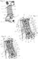
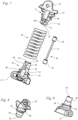
- the Figures 4 to 9 show the structure of the first anti-vibration element 11 in detail.
- the coil spring 20 has a first end 24 into which the first holding element 21 is screwed in. This is also in Fig.5
- the coil spring 20 has a second end 25 into which the second holding element 22 is screwed, as also in Fig.5 shown.
- the second holding element 22 is advantageously arranged on a side of a section of the handle unit 3 that is at the top in the parking position 18. If the working device 1 has a fluid tank 15 on the handle unit 3, the second holding element 22 is advantageously arranged on the fluid tank 15, in the exemplary embodiment on the side of the fluid tank 15 that is at the top in the parking position 18.
- the second holding element 22 is advantageously arranged in a corresponding position.
- the coil spring 20 is advantageously exposed on its outer circumference.
- the coil spring 20 is advantageously not held on its outer circumference.
- the holding elements 21 and 22 advantageously do not fix the coil spring 20 on its outer circumference.
- Fig.5 shows the first anti-vibration element 11 in the unloaded state of the handle unit 3 and motor unit 2.
- the coil spring 20 has a length b measured parallel to the longitudinal center axis 23.
- the coil spring 20 is held with its first end 24 on the first holding element 21.
- the coil spring 20 is advantageously screwed into the holding element 21 with from one to three turns. A different number of turns of the coil spring 20 fixed to the holding element 21 can also be advantageous.
- the first end 24 is held on a holding section 43 of the holding element 21.
- the holding section 43 has a helical groove 46 on its outer circumference for receiving the coil spring 20.
- a guide section 44 of the holding element 21 adjoins the holding section 43.
- the turns of the coil spring 20 are at a distance c from the holding element 21 measured perpendicular to the longitudinal center axis 23.
- the turns of the coil spring 20 do not rest on the holding element 21 in the unloaded state.
- the guide section 44 is located inside the coil spring 20.
- the guide section 44 does not have a groove 46.
- the Guide section 44 has a groove to which the coil spring 20 in the unloaded state has a distance in at least one direction, i.e. in the radial and/or axial direction, for adjusting the spring stiffness.
- the holding element 21 has a front side 31 arranged in an interior space 34 of the coil spring 20.
- the interior space 34 is the interior of the coil spring 20 enclosed by the coil spring 20 and does not denote a space closed off from the outside.
- the front side 31 of the holding element 21 is formed on the guide section 44.
- a first centering element 35 is arranged on the front side 31 of the holding element 21.
- a second centering element 36 is arranged on the front side 32 of the second holding element 22.
- the first centering element 35 is designed as a cone projecting towards the second holding element 22.
- the cone has a cone angle ⁇ .
- the cone angle ⁇ is the angle that the front side 31 forms with the longitudinal center axis 23 in a section through the longitudinal center axis 23.
- the cone angle ⁇ is smaller than the angle ⁇ that the longitudinal center axis 23 forms with the storage surface 19 in the storage position 18 ( Fig.1 ).
- the angle ⁇ is drawn in with a line 19' that runs parallel to the support surface 19.
- the cone angle ⁇ is preferably at least 5° smaller than the inclination angle ⁇ .
- the cone angle ⁇ is advantageously 50° to 75°.
- the centering element 35 forms a centering angle ⁇ with the line 19'.
- the centering angle ⁇ is the smallest angle that the centering element 35 forms with the support surface 19.
- the centering angle ⁇ produces a force that centers the holding elements 21 and 22 with respect to the longitudinal center axis 23.
- the second holding element 22 also has a holding section 43 with a circumferential groove which is screwed into the coil spring 20.
- a guide section 44 adjoins the holding section 43.
- the holding element 22 has a an interior space 34 of the coil spring 20.
- a centering element 36 is formed on the front side 32.
- the centering element 36 is preferably designed to be complementary to the centering element 35 and works together with it to center the holding elements 21 and 22 when the distance between the holding elements 21 and 22 is correspondingly small.
- the centering element 36 is designed as a conical depression.
- a tear-off protection device 30 extends through the interior 34 of the coil spring 20.
- the tear-off protection device 30 is preferably designed as a steel cable. Another design of the tear-off protection device 30 can also be provided. The ends of the tear-off protection device 30 are held on the holding elements 21 and 22. If the coil spring 20 breaks, the motor unit 2 and the handle unit 3 are connected to one another via the tear-off protection device 30.
- the end faces 31 and 32 are at a distance d from one another in the unloaded state.
- the distance d is advantageously at most 30%, in particular at most 20% of the length b of the coil spring 20.
- the distance d in the unloaded state is at most 3 cm, in particular at most 2 cm.
- the unloaded state is the state of the implement 1 in which the implement 1 is standing on the storage surface 19 with the drive motor 10 switched off and no external forces act on the implement 1.
- the end faces 31 and 32 act as a stop between the motor unit 2 and the handle unit 3, for example under heavy loads.
- the distance b is smaller than the difference between the length b of the coil spring 20 in the unloaded state and the block length of the coil spring 20. As a result, the end faces 31 and 32 can come into contact with one another and act as a stop.
- the holding section 43 and the guide section 44 of each holding element 21, 22 have a common length e.
- the common length e is measured parallel to the longitudinal center axis 23 of the coil spring 20.
- the common length e corresponds to the length over which the holding element 21, 22 extends into the interior 34 of the coil spring 20.
- the common length e is advantageously at least 30%, in particular at least 35% of the length b of the helical spring 20 for at least one holding element 21 or 22, in particular for both holding elements 21 and 22.
- the holding elements 21 and 22 move towards each other until the end faces 31 and 32 of the holding elements 21 and 22 come into contact with each other.
- the centering elements 35 and 36 center the holding elements 21 and 22 relative to each other and to the longitudinal center axis 23.
- the tear-off protection 30 comprises a safety cable 37, in particular a steel cable.
- the safety cable 37 is preferably a shear-resistant cable.
- the safety cable 37 has nipples 38 which have an outer diameter that is larger than the safety cable 37.
- the nipples 38 are arranged in receptacles 41 of the holding elements 21 and 22.
- a through opening 40 leads from the receptacles 41 to the front sides 31 and 32.
- the inner diameter of the through opening is dimensioned such that the associated nipple 38 cannot pass through the through opening 40.
- the safety cable 37 thus limits the maximum distance between the holding elements 21 and 22 in the event of a break in the coil spring 20.
- An enlarged section 45 is provided in the section of the through openings 40 adjacent to the front sides 31 and 32.
- the inner diameter of the through-opening 40 increases in the direction of the front side 31, 32 of the holding element 21 or 22 in which the through-opening 40 is arranged.
- the expanded section 45 can also advantageously be designed as a conical recess.
- the angle ⁇ between the wall of the expanded section 45 and the longitudinal center axis 23, which in Fig.6 can be, for example, 5° to 20°.
- the passage opening 40 as Fig.7 shows, via a slot 39 with the circumference of the holding element 21 or 22.
- the slot 39 connects the passage opening 40 with the outer circumference in the guide section 44.
- each holding element 21, 22 has at least one fastening opening 47.
- a fastening screw can protrude through the fastening openings 47, for example, which fixes the holding element 21 to the motor unit 2 and the holding element 22 to the handle unit 3, for example in the area of a fluid tank 15.
- the holding elements 21 and 22 are preferably made of plastic.
- the helical spring 20 is advantageously a steel spring.
- the fact that the centering elements 35, 36 can come into contact with one another means in this case that contact between the centering elements 35 and 36 can occur during a movement of the handle 7 intended for operation.
- the holding elements 21 and 22 can advantageously consist of at least two different materials.
- the holding elements 21 and 22 can advantageously be manufactured using two-component injection molding.
- the holding elements 21 and 22 are advantageously made of a soft component in the area of the end faces 31 and 32.
- the centering elements 35 and 36 are particularly made of an elastic material, preferably an elastomer.
- the holding section 43 advantageously consists of a dimensionally stable plastic.
- radial and axial refer throughout to the radial direction of the longitudinal center axis of the coil spring, i.e. perpendicular to the longitudinal center axis of the coil spring, and to the direction parallel to the longitudinal center axis of the coil spring.
Landscapes
- Engineering & Computer Science (AREA)
- Mechanical Engineering (AREA)
- Life Sciences & Earth Sciences (AREA)
- Wood Science & Technology (AREA)
- Forests & Forestry (AREA)
- Sawing (AREA)
- Springs (AREA)
- Percussive Tools And Related Accessories (AREA)
Claims (15)
- Outil de travail guidé à la main, comprenant une unité moteur (2) et une unité poignée (3), l'unité moteur (2) comprenant un moteur d'entraînement (10) pour l'entraînement d'un outil de l'outil de travail (1), l'unité poignée (3) comprenant une poignée (7), l'unité moteur (2) et l'unité poignée (3) étant reliées entre elles par au moins un élément anti-vibrations (11, 12, 13, 14), un premier élément anti-vibrations (11) comprenant un ressort hélicoïdal (20), un premier élément de maintien (21) étant monté dans une première extrémité (24) du ressort hélicoïdal (20) et un deuxième élément de maintien (22) étant monté dans une deuxième extrémité (25) du ressort hélicoïdal (20), le premier élément de maintien (21) étant relié fixement à l'unité moteur (2) et le deuxième élément de maintien (22) étant relié fixement à l'unité poignée (3), les éléments de maintien (21, 22) présentant des faces d'extrémité (31, 32) qui sont disposés dans un espace intérieur (34) du ressort hélicoïdal (20),
caractérisé en ce que les faces d'extrémité (31, 32) des éléments de maintien (21, 22) présentent des éléments de centrage (35, 36) qui sont aptes à entrer en contact les uns avec les autres et centrer ainsi les éléments de maintien (21, 22) les uns par rapport aux autres, et en ce que les faces d'extrémité (31, 32) des éléments de maintien (21, 22) forment une butée pour le mouvement de la poignée (7). - Outil de travail selon la revendication 1,
caractérisé en ce que les éléments de maintien (21, 22) sont indéformables. - Outil de travail selon la revendication 1 ou la revendication 2, caractérisé en ce qu'un élément de centrage (35) est réalisé sous forme de cône et l'autre élément de centrage (36) est réalisé sous forme de creux.
- Outil de travail selon l'une des revendications 1 à 3,
caractérisé en ce que le premier élément de maintien (21) est vissé dans la première extrémité (24) du ressort hélicoïdal (20) et en ce que le deuxième élément de maintien (22) est vissé dans la deuxième extrémité (25) du ressort hélicoïdal (20). - Outil de travail selon l'une des revendications 1 à 4,
caractérisé en ce que l'axe longitudinal central (23) du ressort hélicoïdal (20) du premier élément anti-vibrations (11) est incliné d'un angle d'inclinaison (α) par rapport à une surface de pose (19) dans une position de pose (18) de l'outil de travail (1) dans laquelle l'outil de travail (1) est posé sur une surface de pose (19) plane et horizontale. - Outil de travail selon la revendication 5,
caractérisé en ce que l'angle de conicité (γ) de l'élément de centrage (35) réalisé sous forme de cône est inférieur à l'angle d'inclinaison (α) de l'axe longitudinal central (23) du ressort hélicoïdal (20). - Outil de travail selon la revendication 6,
caractérisé en ce que l'angle de conicité (γ) de l'élément de centrage (35) réalisé sous forme de cône est inférieur d'au moins 5° à l'angle d'inclinaison (α) de l'axe longitudinal central (23) du ressort hélicoïdal (20). - Outil de travail selon l'une des revendications 5 à 7,
caractérisé en ce que l'angle d'inclinaison (α) est supérieur à 45°. - Outil de travail selon l'une des revendications 1 à 8,
caractérisé en ce que le premier élément anti-vibrations (11) présente une sécurité d'arrachement (30) dont les extrémités sont retenues dans les éléments de maintien, les éléments de maintien comprenant chacun une fente (39) qui s'étend de la périphérie d'une ouverture de passage (40) pour la sécurité d'arrachement (30) à la périphérie extérieure de l'élément de maintien (21, 22). - Outil de travail selon l'une des revendications 1 à 9,
caractérisé en ce que l'ouverture de passage (40) s'élargit dans au moins une section longitudinale en direction de la face d'extrémité (31, 32) de l'élément de maintien (21, 22). - Outil de travail selon l'une des revendications 1 à 10,
caractérisé en ce que les faces d'extrémité (31, 32) des éléments de maintien (21, 22) présentent, à l'état non chargé de l'outil de travail (1), une distance (d) l'une par rapport à l'autre qui représente 30 % au maximum, en particulier 20 % au maximum, d'une longueur (b) du ressort hélicoïdal (20). - Outil de travail selon l'une des revendications 1 à 11,
caractérisé en ce que les éléments de maintien (21, 22) sont en matière plastique. - Outil de travail selon l'une des revendications 1 à 12,
caractérisé en ce que les éléments de centrage (35, 36) sont aptes à venir en contact l'un avec l'autre lors d'un déplacement de la poignée (7) dans une direction (A) correspondant à un déplacement vers le haut en position de pose (18) de l'outil de travail (1). - Outil de travail selon l'une des revendications 1 à 13,
caractérisé en ce que le premier élément anti-vibrations (11) est disposé au voisinage d'un côté avant (16) de la poignée (7) orientée vers l'outil. - Outil de travail selon l'une des revendications 1 à 14,
caractérisé en ce que l'outil de travail guidé à la main (1) est une tronçonneuse.
Priority Applications (3)
| Application Number | Priority Date | Filing Date | Title |
|---|---|---|---|
| EP21203947.3A EP4169669B1 (fr) | 2021-10-21 | 2021-10-21 | Appareil de travail guidé à la main |
| US17/970,177 US20230128835A1 (en) | 2021-10-21 | 2022-10-20 | Handheld work apparatus |
| CN202211292401.XA CN116000373A (zh) | 2021-10-21 | 2022-10-21 | 手持式工作器具 |
Applications Claiming Priority (1)
| Application Number | Priority Date | Filing Date | Title |
|---|---|---|---|
| EP21203947.3A EP4169669B1 (fr) | 2021-10-21 | 2021-10-21 | Appareil de travail guidé à la main |
Publications (2)
| Publication Number | Publication Date |
|---|---|
| EP4169669A1 EP4169669A1 (fr) | 2023-04-26 |
| EP4169669B1 true EP4169669B1 (fr) | 2024-08-07 |
Family
ID=78371826
Family Applications (1)
| Application Number | Title | Priority Date | Filing Date |
|---|---|---|---|
| EP21203947.3A Active EP4169669B1 (fr) | 2021-10-21 | 2021-10-21 | Appareil de travail guidé à la main |
Country Status (3)
| Country | Link |
|---|---|
| US (1) | US20230128835A1 (fr) |
| EP (1) | EP4169669B1 (fr) |
| CN (1) | CN116000373A (fr) |
Family Cites Families (8)
| Publication number | Priority date | Publication date | Assignee | Title |
|---|---|---|---|---|
| SE469824B (sv) * | 1989-10-27 | 1993-09-27 | Electrolux Ab | Motorsågsunderrede |
| DE10105826B4 (de) * | 2001-02-07 | 2012-05-31 | Andreas Stihl Ag & Co | Schwingungsdämpfer zwischen zwei Bauteilen |
| DE10106915C2 (de) * | 2001-02-15 | 2003-02-13 | Benteler Automobiltechnik Gmbh | Federungsanordnung |
| DE10332637A1 (de) * | 2003-07-18 | 2005-02-03 | Andreas Stihl Ag & Co. Kg | Antivibrationselement |
| DE102010011986B4 (de) | 2010-03-19 | 2021-04-01 | Andreas Stihl Ag & Co. Kg | Handgeführtes Arbeitsgerät |
| JP5598213B2 (ja) * | 2010-09-29 | 2014-10-01 | 日立工機株式会社 | 携帯型作業機 |
| DE102013012513A1 (de) * | 2013-07-27 | 2015-01-29 | Andreas Stihl Ag & Co. Kg | "Handgeführtes Arbeitsgerät" |
| DE102013012511A1 (de) * | 2013-07-27 | 2015-01-29 | Andreas Stihl Ag & Co. Kg | "Handgeführtes Arbeitsgerät" |
-
2021
- 2021-10-21 EP EP21203947.3A patent/EP4169669B1/fr active Active
-
2022
- 2022-10-20 US US17/970,177 patent/US20230128835A1/en not_active Abandoned
- 2022-10-21 CN CN202211292401.XA patent/CN116000373A/zh active Pending
Also Published As
| Publication number | Publication date |
|---|---|
| CN116000373A (zh) | 2023-04-25 |
| EP4169669A1 (fr) | 2023-04-26 |
| US20230128835A1 (en) | 2023-04-27 |
Similar Documents
| Publication | Publication Date | Title |
|---|---|---|
| EP2829363B1 (fr) | Appareil de travail portatif | |
| DE102007022115B4 (de) | Handgeführte Motorsäge | |
| EP3058808B1 (fr) | Appareil de travail portatif dote d'une section telescopique | |
| EP1800805B1 (fr) | Poignée d'un outil à main | |
| EP2763819B1 (fr) | Dispositif de préhension ou de serrage | |
| DE69103097T2 (de) | Schwingungsreduzierender Kettensägehandgriff. | |
| DE19530712A1 (de) | Antivibrationselement zur Anordnung zwischen einer Motoreinheit und einer Griffeinheit | |
| DE102009054923B4 (de) | Handwerkzeugmaschine | |
| DE10034437B4 (de) | Handgeführtes Arbeitsgerät | |
| EP1332023A1 (fr) | Machine-outil a main comportant au moins une poignee | |
| EP4234140A2 (fr) | Outil de vissage et logement d'outil pour un tel outil de vissage | |
| DE102008000516A1 (de) | Zusatzhandgriff sowie Handwerkzeugmaschine | |
| EP2160272A1 (fr) | Unité de boîtier pour des machines-outils manuelles | |
| DE102010011986B4 (de) | Handgeführtes Arbeitsgerät | |
| EP3599059B1 (fr) | Outil de travail à main et procédé de montage d'un élément anti-vibratoire d'un outil de travail à main | |
| EP2050328B1 (fr) | Appareil de travail manuel | |
| DE10361295A1 (de) | Griffrohr eines handgeführten Arbeitsgerätes | |
| DE9016415U1 (de) | Handgeführte Elektrowerkzeugmaschine mit einer Einrichtung zum Einstellen des Drehmoments | |
| EP2167265B1 (fr) | Module de séparation par rupture pour une machine-outil, machine-outil comprenant un tel module de séparation par rupture et procédé de séparation par rupture | |
| EP4169669A1 (fr) | Appareil de travail guidé à la main | |
| DE102019111144A1 (de) | Spindeltrieb mit Verdrehsicherung | |
| EP3292932B1 (fr) | Ensemble à ressort permettant de générer la force de serrage d'un dispositif de serrage et dispositif de serrage pourvu d'un tel ensemble à ressort | |
| EP4389361A1 (fr) | Outil manuel | |
| DE202019105846U1 (de) | Elektrohandwerkzeugmaschine | |
| DE29910049U1 (de) | Heckenschere |
Legal Events
| Date | Code | Title | Description |
|---|---|---|---|
| PUAI | Public reference made under article 153(3) epc to a published international application that has entered the european phase |
Free format text: ORIGINAL CODE: 0009012 |
|
| STAA | Information on the status of an ep patent application or granted ep patent |
Free format text: STATUS: THE APPLICATION HAS BEEN PUBLISHED |
|
| AK | Designated contracting states |
Kind code of ref document: A1 Designated state(s): AL AT BE BG CH CY CZ DE DK EE ES FI FR GB GR HR HU IE IS IT LI LT LU LV MC MK MT NL NO PL PT RO RS SE SI SK SM TR |
|
| STAA | Information on the status of an ep patent application or granted ep patent |
Free format text: STATUS: REQUEST FOR EXAMINATION WAS MADE |
|
| 17P | Request for examination filed |
Effective date: 20231011 |
|
| RBV | Designated contracting states (corrected) |
Designated state(s): AL AT BE BG CH CY CZ DE DK EE ES FI FR GB GR HR HU IE IS IT LI LT LU LV MC MK MT NL NO PL PT RO RS SE SI SK SM TR |
|
| GRAJ | Information related to disapproval of communication of intention to grant by the applicant or resumption of examination proceedings by the epo deleted |
Free format text: ORIGINAL CODE: EPIDOSDIGR1 |
|
| STAA | Information on the status of an ep patent application or granted ep patent |
Free format text: STATUS: GRANT OF PATENT IS INTENDED |
|
| GRAP | Despatch of communication of intention to grant a patent |
Free format text: ORIGINAL CODE: EPIDOSNIGR1 |
|
| RIC1 | Information provided on ipc code assigned before grant |
Ipc: B27B 17/00 20060101ALI20240130BHEP Ipc: B25F 5/00 20060101AFI20240130BHEP |
|
| INTG | Intention to grant announced |
Effective date: 20240213 |
|
| GRAS | Grant fee paid |
Free format text: ORIGINAL CODE: EPIDOSNIGR3 |
|
| GRAA | (expected) grant |
Free format text: ORIGINAL CODE: 0009210 |
|
| STAA | Information on the status of an ep patent application or granted ep patent |
Free format text: STATUS: THE PATENT HAS BEEN GRANTED |
|
| AK | Designated contracting states |
Kind code of ref document: B1 Designated state(s): AL AT BE BG CH CY CZ DE DK EE ES FI FR GB GR HR HU IE IS IT LI LT LU LV MC MK MT NL NO PL PT RO RS SE SI SK SM TR |
|
| REG | Reference to a national code |
Ref country code: GB Ref legal event code: FG4D Free format text: NOT ENGLISH |
|
| REG | Reference to a national code |
Ref country code: CH Ref legal event code: EP |
|
| REG | Reference to a national code |
Ref country code: DE Ref legal event code: R096 Ref document number: 502021004670 Country of ref document: DE |
|
| REG | Reference to a national code |
Ref country code: IE Ref legal event code: FG4D Free format text: LANGUAGE OF EP DOCUMENT: GERMAN |
|
| REG | Reference to a national code |
Ref country code: LT Ref legal event code: MG9D |
|
| REG | Reference to a national code |
Ref country code: NL Ref legal event code: MP Effective date: 20240807 |
|
| PG25 | Lapsed in a contracting state [announced via postgrant information from national office to epo] |
Ref country code: NO Free format text: LAPSE BECAUSE OF FAILURE TO SUBMIT A TRANSLATION OF THE DESCRIPTION OR TO PAY THE FEE WITHIN THE PRESCRIBED TIME-LIMIT Effective date: 20241107 |
|
| PG25 | Lapsed in a contracting state [announced via postgrant information from national office to epo] |
Ref country code: NL Free format text: LAPSE BECAUSE OF FAILURE TO SUBMIT A TRANSLATION OF THE DESCRIPTION OR TO PAY THE FEE WITHIN THE PRESCRIBED TIME-LIMIT Effective date: 20240807 Ref country code: GR Free format text: LAPSE BECAUSE OF FAILURE TO SUBMIT A TRANSLATION OF THE DESCRIPTION OR TO PAY THE FEE WITHIN THE PRESCRIBED TIME-LIMIT Effective date: 20241108 Ref country code: PT Free format text: LAPSE BECAUSE OF FAILURE TO SUBMIT A TRANSLATION OF THE DESCRIPTION OR TO PAY THE FEE WITHIN THE PRESCRIBED TIME-LIMIT Effective date: 20241209 Ref country code: PL Free format text: LAPSE BECAUSE OF FAILURE TO SUBMIT A TRANSLATION OF THE DESCRIPTION OR TO PAY THE FEE WITHIN THE PRESCRIBED TIME-LIMIT Effective date: 20240807 Ref country code: FI Free format text: LAPSE BECAUSE OF FAILURE TO SUBMIT A TRANSLATION OF THE DESCRIPTION OR TO PAY THE FEE WITHIN THE PRESCRIBED TIME-LIMIT Effective date: 20240807 |
|
| PG25 | Lapsed in a contracting state [announced via postgrant information from national office to epo] |
Ref country code: BG Free format text: LAPSE BECAUSE OF FAILURE TO SUBMIT A TRANSLATION OF THE DESCRIPTION OR TO PAY THE FEE WITHIN THE PRESCRIBED TIME-LIMIT Effective date: 20240807 |
|
| PG25 | Lapsed in a contracting state [announced via postgrant information from national office to epo] |
Ref country code: LV Free format text: LAPSE BECAUSE OF FAILURE TO SUBMIT A TRANSLATION OF THE DESCRIPTION OR TO PAY THE FEE WITHIN THE PRESCRIBED TIME-LIMIT Effective date: 20240807 |
|
| PG25 | Lapsed in a contracting state [announced via postgrant information from national office to epo] |
Ref country code: IS Free format text: LAPSE BECAUSE OF FAILURE TO SUBMIT A TRANSLATION OF THE DESCRIPTION OR TO PAY THE FEE WITHIN THE PRESCRIBED TIME-LIMIT Effective date: 20241207 |
|
| PG25 | Lapsed in a contracting state [announced via postgrant information from national office to epo] |
Ref country code: HR Free format text: LAPSE BECAUSE OF FAILURE TO SUBMIT A TRANSLATION OF THE DESCRIPTION OR TO PAY THE FEE WITHIN THE PRESCRIBED TIME-LIMIT Effective date: 20240807 |
|
| PG25 | Lapsed in a contracting state [announced via postgrant information from national office to epo] |
Ref country code: ES Free format text: LAPSE BECAUSE OF FAILURE TO SUBMIT A TRANSLATION OF THE DESCRIPTION OR TO PAY THE FEE WITHIN THE PRESCRIBED TIME-LIMIT Effective date: 20240807 Ref country code: RS Free format text: LAPSE BECAUSE OF FAILURE TO SUBMIT A TRANSLATION OF THE DESCRIPTION OR TO PAY THE FEE WITHIN THE PRESCRIBED TIME-LIMIT Effective date: 20241107 |
|
| PG25 | Lapsed in a contracting state [announced via postgrant information from national office to epo] |
Ref country code: RS Free format text: LAPSE BECAUSE OF FAILURE TO SUBMIT A TRANSLATION OF THE DESCRIPTION OR TO PAY THE FEE WITHIN THE PRESCRIBED TIME-LIMIT Effective date: 20241107 Ref country code: PT Free format text: LAPSE BECAUSE OF FAILURE TO SUBMIT A TRANSLATION OF THE DESCRIPTION OR TO PAY THE FEE WITHIN THE PRESCRIBED TIME-LIMIT Effective date: 20241209 Ref country code: PL Free format text: LAPSE BECAUSE OF FAILURE TO SUBMIT A TRANSLATION OF THE DESCRIPTION OR TO PAY THE FEE WITHIN THE PRESCRIBED TIME-LIMIT Effective date: 20240807 Ref country code: NO Free format text: LAPSE BECAUSE OF FAILURE TO SUBMIT A TRANSLATION OF THE DESCRIPTION OR TO PAY THE FEE WITHIN THE PRESCRIBED TIME-LIMIT Effective date: 20241107 Ref country code: NL Free format text: LAPSE BECAUSE OF FAILURE TO SUBMIT A TRANSLATION OF THE DESCRIPTION OR TO PAY THE FEE WITHIN THE PRESCRIBED TIME-LIMIT Effective date: 20240807 Ref country code: LV Free format text: LAPSE BECAUSE OF FAILURE TO SUBMIT A TRANSLATION OF THE DESCRIPTION OR TO PAY THE FEE WITHIN THE PRESCRIBED TIME-LIMIT Effective date: 20240807 Ref country code: IS Free format text: LAPSE BECAUSE OF FAILURE TO SUBMIT A TRANSLATION OF THE DESCRIPTION OR TO PAY THE FEE WITHIN THE PRESCRIBED TIME-LIMIT Effective date: 20241207 Ref country code: HR Free format text: LAPSE BECAUSE OF FAILURE TO SUBMIT A TRANSLATION OF THE DESCRIPTION OR TO PAY THE FEE WITHIN THE PRESCRIBED TIME-LIMIT Effective date: 20240807 Ref country code: GR Free format text: LAPSE BECAUSE OF FAILURE TO SUBMIT A TRANSLATION OF THE DESCRIPTION OR TO PAY THE FEE WITHIN THE PRESCRIBED TIME-LIMIT Effective date: 20241108 Ref country code: FI Free format text: LAPSE BECAUSE OF FAILURE TO SUBMIT A TRANSLATION OF THE DESCRIPTION OR TO PAY THE FEE WITHIN THE PRESCRIBED TIME-LIMIT Effective date: 20240807 Ref country code: ES Free format text: LAPSE BECAUSE OF FAILURE TO SUBMIT A TRANSLATION OF THE DESCRIPTION OR TO PAY THE FEE WITHIN THE PRESCRIBED TIME-LIMIT Effective date: 20240807 Ref country code: BG Free format text: LAPSE BECAUSE OF FAILURE TO SUBMIT A TRANSLATION OF THE DESCRIPTION OR TO PAY THE FEE WITHIN THE PRESCRIBED TIME-LIMIT Effective date: 20240807 |
|
| PG25 | Lapsed in a contracting state [announced via postgrant information from national office to epo] |
Ref country code: DK Free format text: LAPSE BECAUSE OF FAILURE TO SUBMIT A TRANSLATION OF THE DESCRIPTION OR TO PAY THE FEE WITHIN THE PRESCRIBED TIME-LIMIT Effective date: 20240807 Ref country code: SM Free format text: LAPSE BECAUSE OF FAILURE TO SUBMIT A TRANSLATION OF THE DESCRIPTION OR TO PAY THE FEE WITHIN THE PRESCRIBED TIME-LIMIT Effective date: 20240807 |
|
| PG25 | Lapsed in a contracting state [announced via postgrant information from national office to epo] |
Ref country code: EE Free format text: LAPSE BECAUSE OF FAILURE TO SUBMIT A TRANSLATION OF THE DESCRIPTION OR TO PAY THE FEE WITHIN THE PRESCRIBED TIME-LIMIT Effective date: 20240807 |
|
| PG25 | Lapsed in a contracting state [announced via postgrant information from national office to epo] |
Ref country code: CZ Free format text: LAPSE BECAUSE OF FAILURE TO SUBMIT A TRANSLATION OF THE DESCRIPTION OR TO PAY THE FEE WITHIN THE PRESCRIBED TIME-LIMIT Effective date: 20240807 |
|
| PG25 | Lapsed in a contracting state [announced via postgrant information from national office to epo] |
Ref country code: SK Free format text: LAPSE BECAUSE OF FAILURE TO SUBMIT A TRANSLATION OF THE DESCRIPTION OR TO PAY THE FEE WITHIN THE PRESCRIBED TIME-LIMIT Effective date: 20240807 |
|
| REG | Reference to a national code |
Ref country code: DE Ref legal event code: R097 Ref document number: 502021004670 Country of ref document: DE |
|
| REG | Reference to a national code |
Ref country code: CH Ref legal event code: PL |
|
| PLBE | No opposition filed within time limit |
Free format text: ORIGINAL CODE: 0009261 |
|
| STAA | Information on the status of an ep patent application or granted ep patent |
Free format text: STATUS: NO OPPOSITION FILED WITHIN TIME LIMIT |
|
| PG25 | Lapsed in a contracting state [announced via postgrant information from national office to epo] |
Ref country code: MC Free format text: LAPSE BECAUSE OF FAILURE TO SUBMIT A TRANSLATION OF THE DESCRIPTION OR TO PAY THE FEE WITHIN THE PRESCRIBED TIME-LIMIT Effective date: 20240807 |
|
| PG25 | Lapsed in a contracting state [announced via postgrant information from national office to epo] |
Ref country code: LU Free format text: LAPSE BECAUSE OF NON-PAYMENT OF DUE FEES Effective date: 20241021 Ref country code: BE Free format text: LAPSE BECAUSE OF NON-PAYMENT OF DUE FEES Effective date: 20241031 |
|
| 26N | No opposition filed |
Effective date: 20250508 |
|
| PG25 | Lapsed in a contracting state [announced via postgrant information from national office to epo] |
Ref country code: FR Free format text: LAPSE BECAUSE OF NON-PAYMENT OF DUE FEES Effective date: 20241031 |
|
| PG25 | Lapsed in a contracting state [announced via postgrant information from national office to epo] |
Ref country code: CH Free format text: LAPSE BECAUSE OF NON-PAYMENT OF DUE FEES Effective date: 20241031 |
|
| REG | Reference to a national code |
Ref country code: BE Ref legal event code: MM Effective date: 20241031 |
|
| PG25 | Lapsed in a contracting state [announced via postgrant information from national office to epo] |
Ref country code: SE Free format text: LAPSE BECAUSE OF FAILURE TO SUBMIT A TRANSLATION OF THE DESCRIPTION OR TO PAY THE FEE WITHIN THE PRESCRIBED TIME-LIMIT Effective date: 20240807 |
|
| PG25 | Lapsed in a contracting state [announced via postgrant information from national office to epo] |
Ref country code: IE Free format text: LAPSE BECAUSE OF NON-PAYMENT OF DUE FEES Effective date: 20241021 |
|
| PG25 | Lapsed in a contracting state [announced via postgrant information from national office to epo] |
Ref country code: RO Free format text: LAPSE BECAUSE OF FAILURE TO SUBMIT A TRANSLATION OF THE DESCRIPTION OR TO PAY THE FEE WITHIN THE PRESCRIBED TIME-LIMIT Effective date: 20240807 |
|
| PGFP | Annual fee paid to national office [announced via postgrant information from national office to epo] |
Ref country code: DE Payment date: 20251028 Year of fee payment: 5 |
|
| PGFP | Annual fee paid to national office [announced via postgrant information from national office to epo] |
Ref country code: AT Payment date: 20260113 Year of fee payment: 5 |
|
| PG25 | Lapsed in a contracting state [announced via postgrant information from national office to epo] |
Ref country code: IT Free format text: LAPSE BECAUSE OF FAILURE TO SUBMIT A TRANSLATION OF THE DESCRIPTION OR TO PAY THE FEE WITHIN THE PRESCRIBED TIME-LIMIT Effective date: 20240807 Ref country code: CY Free format text: LAPSE BECAUSE OF FAILURE TO SUBMIT A TRANSLATION OF THE DESCRIPTION OR TO PAY THE FEE WITHIN THE PRESCRIBED TIME-LIMIT; INVALID AB INITIO Effective date: 20211021 |
|
| PG25 | Lapsed in a contracting state [announced via postgrant information from national office to epo] |
Ref country code: HU Free format text: LAPSE BECAUSE OF FAILURE TO SUBMIT A TRANSLATION OF THE DESCRIPTION OR TO PAY THE FEE WITHIN THE PRESCRIBED TIME-LIMIT; INVALID AB INITIO Effective date: 20211021 |