EP3599672B1 - Anschluss mit hilfshebel zum anschliessen, und verpackungsverfahren eines solchen anschlusses - Google Patents
Anschluss mit hilfshebel zum anschliessen, und verpackungsverfahren eines solchen anschlusses Download PDFInfo
- Publication number
- EP3599672B1 EP3599672B1 EP19188291.9A EP19188291A EP3599672B1 EP 3599672 B1 EP3599672 B1 EP 3599672B1 EP 19188291 A EP19188291 A EP 19188291A EP 3599672 B1 EP3599672 B1 EP 3599672B1
- Authority
- EP
- European Patent Office
- Prior art keywords
- lever
- connector
- locking means
- secondary locking
- housing
- Prior art date
- Legal status (The legal status is an assumption and is not a legal conclusion. Google has not performed a legal analysis and makes no representation as to the accuracy of the status listed.)
- Active
Links
Images


Classifications
-
- H—ELECTRICITY
- H01—ELECTRIC ELEMENTS
- H01R—ELECTRICALLY-CONDUCTIVE CONNECTIONS; STRUCTURAL ASSOCIATIONS OF A PLURALITY OF MUTUALLY-INSULATED ELECTRICAL CONNECTING ELEMENTS; COUPLING DEVICES; CURRENT COLLECTORS
- H01R13/00—Details of coupling devices of the kinds covered by groups H01R12/70 or H01R24/00 - H01R33/00
- H01R13/62—Means for facilitating engagement or disengagement of coupling parts or for holding them in engagement
- H01R13/627—Snap or like fastening
-
- H—ELECTRICITY
- H01—ELECTRIC ELEMENTS
- H01R—ELECTRICALLY-CONDUCTIVE CONNECTIONS; STRUCTURAL ASSOCIATIONS OF A PLURALITY OF MUTUALLY-INSULATED ELECTRICAL CONNECTING ELEMENTS; COUPLING DEVICES; CURRENT COLLECTORS
- H01R13/00—Details of coupling devices of the kinds covered by groups H01R12/70 or H01R24/00 - H01R33/00
- H01R13/62—Means for facilitating engagement or disengagement of coupling parts or for holding them in engagement
- H01R13/629—Additional means for facilitating engagement or disengagement of coupling parts, e.g. aligning or guiding means, levers, gas pressure electrical locking indicators, manufacturing tolerances
- H01R13/62933—Comprising exclusively pivoting lever
- H01R13/62955—Pivoting lever comprising supplementary/additional locking means
-
- H—ELECTRICITY
- H01—ELECTRIC ELEMENTS
- H01R—ELECTRICALLY-CONDUCTIVE CONNECTIONS; STRUCTURAL ASSOCIATIONS OF A PLURALITY OF MUTUALLY-INSULATED ELECTRICAL CONNECTING ELEMENTS; COUPLING DEVICES; CURRENT COLLECTORS
- H01R13/00—Details of coupling devices of the kinds covered by groups H01R12/70 or H01R24/00 - H01R33/00
- H01R13/46—Bases; Cases
- H01R13/502—Bases; Cases composed of different pieces
-
- H—ELECTRICITY
- H01—ELECTRIC ELEMENTS
- H01R—ELECTRICALLY-CONDUCTIVE CONNECTIONS; STRUCTURAL ASSOCIATIONS OF A PLURALITY OF MUTUALLY-INSULATED ELECTRICAL CONNECTING ELEMENTS; COUPLING DEVICES; CURRENT COLLECTORS
- H01R13/00—Details of coupling devices of the kinds covered by groups H01R12/70 or H01R24/00 - H01R33/00
- H01R13/62—Means for facilitating engagement or disengagement of coupling parts or for holding them in engagement
- H01R13/629—Additional means for facilitating engagement or disengagement of coupling parts, e.g. aligning or guiding means, levers, gas pressure electrical locking indicators, manufacturing tolerances
-
- H—ELECTRICITY
- H01—ELECTRIC ELEMENTS
- H01R—ELECTRICALLY-CONDUCTIVE CONNECTIONS; STRUCTURAL ASSOCIATIONS OF A PLURALITY OF MUTUALLY-INSULATED ELECTRICAL CONNECTING ELEMENTS; COUPLING DEVICES; CURRENT COLLECTORS
- H01R13/00—Details of coupling devices of the kinds covered by groups H01R12/70 or H01R24/00 - H01R33/00
- H01R13/62—Means for facilitating engagement or disengagement of coupling parts or for holding them in engagement
- H01R13/629—Additional means for facilitating engagement or disengagement of coupling parts, e.g. aligning or guiding means, levers, gas pressure electrical locking indicators, manufacturing tolerances
- H01R13/62933—Comprising exclusively pivoting lever
- H01R13/62938—Pivoting lever comprising own camming means
-
- H—ELECTRICITY
- H01—ELECTRIC ELEMENTS
- H01R—ELECTRICALLY-CONDUCTIVE CONNECTIONS; STRUCTURAL ASSOCIATIONS OF A PLURALITY OF MUTUALLY-INSULATED ELECTRICAL CONNECTING ELEMENTS; COUPLING DEVICES; CURRENT COLLECTORS
- H01R13/00—Details of coupling devices of the kinds covered by groups H01R12/70 or H01R24/00 - H01R33/00
- H01R13/62—Means for facilitating engagement or disengagement of coupling parts or for holding them in engagement
- H01R13/639—Additional means for holding or locking coupling parts together, after engagement, e.g. separate keylock, retainer strap
-
- H—ELECTRICITY
- H01—ELECTRIC ELEMENTS
- H01R—ELECTRICALLY-CONDUCTIVE CONNECTIONS; STRUCTURAL ASSOCIATIONS OF A PLURALITY OF MUTUALLY-INSULATED ELECTRICAL CONNECTING ELEMENTS; COUPLING DEVICES; CURRENT COLLECTORS
- H01R13/00—Details of coupling devices of the kinds covered by groups H01R12/70 or H01R24/00 - H01R33/00
- H01R13/64—Means for preventing incorrect coupling
- H01R13/642—Means for preventing incorrect coupling by position or shape of contact members
-
- H—ELECTRICITY
- H01—ELECTRIC ELEMENTS
- H01R—ELECTRICALLY-CONDUCTIVE CONNECTIONS; STRUCTURAL ASSOCIATIONS OF A PLURALITY OF MUTUALLY-INSULATED ELECTRICAL CONNECTING ELEMENTS; COUPLING DEVICES; CURRENT COLLECTORS
- H01R13/00—Details of coupling devices of the kinds covered by groups H01R12/70 or H01R24/00 - H01R33/00
- H01R13/62—Means for facilitating engagement or disengagement of coupling parts or for holding them in engagement
- H01R13/629—Additional means for facilitating engagement or disengagement of coupling parts, e.g. aligning or guiding means, levers, gas pressure electrical locking indicators, manufacturing tolerances
- H01R13/62933—Comprising exclusively pivoting lever
- H01R13/62944—Pivoting lever comprising gear teeth
-
- H—ELECTRICITY
- H01—ELECTRIC ELEMENTS
- H01R—ELECTRICALLY-CONDUCTIVE CONNECTIONS; STRUCTURAL ASSOCIATIONS OF A PLURALITY OF MUTUALLY-INSULATED ELECTRICAL CONNECTING ELEMENTS; COUPLING DEVICES; CURRENT COLLECTORS
- H01R2201/00—Connectors or connections adapted for particular applications
- H01R2201/26—Connectors or connections adapted for particular applications for vehicles
Definitions
- the invention relates to the field of connectors, and in particular that of automotive connectors.
- the invention relates in particular to a connector comprising a lever and locking means as well as a method of packaging a connector.
- Connectors are used to transmit signals or electrical energy between cables, devices (computer, lighting, etc.) or motors.
- electrical connectors have electrical contacts in greater or lesser numbers, or even of greater or lesser sizes.
- the connectors in order to avoid musculoskeletal disorders for operators responsible for assembling and connecting the connectors together, in order to ensure an easy and reliable connection, and in order to avoid the risks of faulty connections, the connectors, and in particular the connectors for the automotive industry, may be equipped with a coupling assistance lever.
- connectors are known with a lever mounted in rotation on a housing, the lever comprising two lever arms articulated around an axis of rotation, each respectively on a face of the housing, perpendicular to the axis of rotation. Each of these arms is provided with teeth cooperating with racks of a counter-connector.
- the lever is then movable between two positions: an open position, corresponding to a pre-coupling or start of coupling position of the connector with a counter-connector, and a closed position, corresponding to a completely coupled position of the connector with the counter-connector.
- the lever is placed in the open position when the connector is arranged opposite a counter-connector to couple the connector with the counter-connector.
- the lever is tilted, from this open position to its closed position.
- the teeth of the lever engage with the racks of the counter-connector, to couple and connect the connector with the counter-connector.
- the connector and counter-connector are fully mated and connected.
- This type of connector may be provided with locking means which block the lever in its closed position, in order to prevent the lever from tilting, inadvertently or under the effect of vibrations, towards its open position and the connector and counter-connector from disconnecting.
- Connectors of this type are described, for example, in the document EP2675021A2 or in the document EP2863490A1 .
- the lever is in the closed position, without however being locked.
- the connector in addition to the fact that the connector can be packaged by limiting the volume it occupies and by reducing or avoiding the lever being broken, the connector can be stored for long periods without the effectiveness of the lever locking means degrading over time.
- the locking means with which the connectors are equipped are often in the form of a lock made by molding a plastic material. It is therefore necessary to prevent elements of the locking means from being kept under stress for long periods. Under the effect of temperature and/or time, the plastic material can creep and/or deform, which can lead to malfunction and/or loss of reliability of the locking means.
- the locking means do not remain under stress for extended periods.
- the connector according to the invention can comprise locking means which comprise at least one flexible branch cooperating with the housing to block the lever in the closed position, this flexible branch not being under stress (i.e. not under permanent stress) when the locking means are in the delivery position or in the locking position.
- the connector according to the invention may, in addition, optionally include one or other of the characteristics mentioned in claims 2 to 10, considered in isolation or in combination with one or more others.
- the invention relates to a method of packaging a connector, according to claim 11.
- the connector is packaged, for example, in a box, by placing the lever in the closed position and the locking means in a delivery position, distinct from the locking and unlocking positions, in which the locking means are not under stress.
- the connector 1 comprises a housing 2, a lever 3 and locking means 4. These elements are made of molded resin having dielectric properties.
- the housing 2 has a coupling face 5 with a counter-connector (not shown) and a wire guide passage 6.
- the coupling face 5 is provided with contacts (not shown) electrically connected to wires or cables (not shown) exiting the connector 1 through the wire guide passage 6.
- These contacts are intended to be connected with contacts of the counter-connector (not shown), by bringing the connector 1 and the counter-connector closer to each other, by fitting them into each other, in a coupling direction D, then by coupling them to each other by rotating the lever 3, about an axis of rotation A, from an open position of the lever ( figure 3 ) to a closed position of the lever ( figure 2 ).
- the open position corresponds to a position in which the connector 1 is positioned to be mated with a counter-connector.
- the closed position corresponds to a position in which the connector 1 is completely mated with the counter-connector and in which the contacts of the connector and the counter-connector are electrically connected to each other.
- the axis of rotation A of the lever 3 is parallel to the coupling face 5 and perpendicular to the coupling direction D with the counter-connector.
- the lever 3 comprises two arms 7.
- the arms 7 are connected by one of their ends to a handle 8.
- Their other end is provided with a flange 9 rotatably mounted on the housing 2 about the axis of rotation A.
- Each flange 9 is provided with teeth 10 configured to cooperate with a respective rack present on the counter-connector, in order to couple the connector 1 with the counter-connector when the lever 3 is tilted from its open position ( figure 3 ) to its closed position ( figure 2 ).
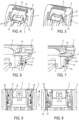
- the locking means 4 are, in the exemplary embodiment described here, in the form of a lock mounted to slide on the lever 3 in a translation direction T, parallel to a plane perpendicular to the axis of rotation A. More particularly, the lock is mounted to move in translation on the handle 8 between successively, along the direction T, a delivery position, an unlocking position and a locking position.
- the lock comprises an actuating surface 11 under which there is a slider 12.
- This slider 12 comprises two branches 13 extending longitudinally between an end connected to a base 14 (see Figures 10, 12 and 15 ) and a free end.
- the branches 13 are flexible and can elastically deform and flex towards the base 14.
- the base 14 has two ribs 15 each extending laterally towards the outside of the connector (see figures 1 , 4, 6 and 7 ). These ribs 15 extend longitudinally in the direction T. They penetrate and slide, in the direction T, in slides 16 formed in the handle 8 of the lever 3.
- Each branch 13 comprises a locking tooth 17 and an unlocking tooth 18.
- These locking teeth 17 and unlocking teeth 18 extend from each of the branches 13, towards the outside of the connector 1, parallel to the axis of rotation A of the lever 3 (see figures 1 , 6 and 7 ).
- Each locking tooth 17 is shaped to cooperate with the lever 3 and prevent the free movement of the lock 4 from its unlocked position to its locked position ( figure 12 ) and vice versa ( Figure 15 ).
- Each unlocking tooth 18 is shaped to cooperate with the housing 2, when the lock 4 is in the unlocking position and the lever 3 is tilted from its open position to its closed position ( Figure 13 ), and thus deflect the branches 13 each comprising the unlocking teeth 18 so that the lock 4 escapes the stopper 26 and can be moved from its unlocking position to its locking position.
- the connector 1 is packaged for storage and transport, for example in a box, in bulk or in a cell provided for this purpose. In accordance with the invention, it is packaged, as shown in the figure 2 , by placing the lever 3 in the closed position and the locking means 4 in the delivery position.
- these primary locking means comprise a lug 19 and an opening 20 provided in a locking tab 21, which is elastic and comes in a manner with the housing 2.
- the lug 19 is engaged in the opening 20.
- the lock 4 in the delivery position does not interact with the elastic tab 21. It is then sufficient to press on the free end of the tab 21 to disengage the lug 19 from the opening 20 and release the lever 3.
- the lock 4 when the lever 3 is in the closed position and it is desired to lock it in this position so that it does not tilt inadvertently, for example because pressure has been involuntarily exerted on the tab 21, the lock 4 must be positioned in the locked position.
- the lock 4 thus forms secondary locking means.
- the lock 4 comprises two hooks 22 located opposite each other, each respectively, at a longitudinal edge of the tongue 21.
- Each hook 22 has a U shape (when seen in cross section).
- Each hook 22 thus forms a gutter or slide in which a rib 23 extending the tongue 21, laterally, outwards, can engage.
- the branches 13 are not constrained.
- the locking teeth 17 and unlocking teeth 18 do not interfere with either the housing 2 or the lever 3. They are freely housed in notches or recesses 24 provided on the internal face of the walls of the housing 2.
- the branches 13 are not constrained.
- the locking teeth 17 and unlocking teeth 18 do not interfere with either the housing 2 or the lever 3. In particular, they fit freely into the notches or recesses 24 provided on the internal face of the walls of the housing 2.
- the lock 4 is moved, in the direction T, from its delivery position to its unlocking position.
- protrusions 25 placed on the lock 4 and on the lever 3 interfere to offer a slight resistance that the operator can easily overcome ( figure 11 ). This gives the operator the sensation of moving through a notch.
- the lock 4 is blocked by the locking teeth 17 which are in abutment on stops 26 made of the same material as the lever 3 and which prevent the movement of the lock 4 further towards its locking position ( Figure 12 ).
- the protrusions 25 also interfere to retain the lock in this unlocked position ( Figure 13 ).
- the respective mating faces 12 of the connector 1 and the counter-connector are presented facing each other.
- the connector 1 and the counter-connector begin to be fitted into each other until the teeth 10 of the lever 3 can cooperate with the racks of the counter-connector.
- the operator can then tilt the lever 3 from its open position to its closed position, to fully mate the connector 1 with the counter-connector.
- Lock 4 can then be moved to its locking position ( figures 7, 9 , 14 and 15 ).
- the beveled shapes of the unlocking teeth 18 facilitate this movement.
- the locking teeth 17 and unlocking teeth 18 are again housed in notches or recesses 24 provided on the internal face of the walls of the housing 2.
- the branches 13 are no longer stressed.
- the stress exerted on the branches 13 is limited to the duration of the passage into the unlocking position of the lock 4.
- This unlocking position corresponds to an intermediate position in which the lock is not intended to remain for a long time (and in any case not long enough for the plastic material to flow and for the branches 3 to be deformed relative to the rest position in which they are when the lock is in the delivery position or in the locking position).
- the operator moves lock 4 from its locking position ( Figures 14 and 15 ) to its unlocked position ( figure 13 ).
- the beveled shapes of the locking teeth 17 facilitate this movement (see figure 15 ).
- the branches 13 bend when they pass over the stops 26 of the lever 3.
- the unlocking teeth 18 are placed on the ribs 27.
- the initial position is returned which allows the lug 19 to be released from the opening 20 by pressing on the free end of the tab 21.
- the lever 3 can be tilted towards its open position by uncoupling the connector 1 and the counter-connector.
Landscapes
- Details Of Connecting Devices For Male And Female Coupling (AREA)
Claims (11)
- Verbinder (1) mit- ein Gehäuse (2),- einen Verbindungsunterstützungshebel (3), der an dem Gehäuse (2) um eine Drehachse (A) zwischen mindestens einer offenen Position, in der ein Gegenverbinder mit dem Verbinder (1) in einer Kupplungsrichtung (D) im Wesentlichen senkrecht zu der Drehachse (A) des Hebels (3) gekoppelt werden kann, und einer geschlossenen Position, in der der Verbinder (1) und der Gegenverbinder miteinander gekoppelt sind, gelenkig verbunden ist,- primäre Verriegelungsmittel (19, 20, 21), um den Hebel (3) in der geschlossenen Position zu verriegeln ;- sekundäre Verriegelungsmittel (4) des Hebels (3), die zwischen einer Verriegelungsposition, in der die sekundären Verriegelungsmittel (4) des Hebels (3) mit den primären Verriegelungsmitteln (19, 20, 21) zusammenwirken, um den Hebel (3) in seiner geschlossenen Position zu blockieren, und einer Entriegelungsposition, in der die sekundären Verriegelungsmittel (4) des Hebels (3) den Hebel (3) freigeben, um eine Drehung des Hebels (3) um die Drehachse (A) zu ermöglichen, in seine offene Position beweglich sind,und wobei die sekundären Verriegelungsmittel (4)- nicht von ihrer Entriegelungsposition in ihre Verriegelungsposition bewegt werden können, wenn sich der Hebel (3) in der offenen Position befindet, und- können nach Drehung des Hebels (3) aus seiner offenen in seine geschlossene Position aus ihrer entriegelten in ihre verriegelte Position bewegt werden,dadurch gekennzeichnet, dassdie sekundären Verriegelungsmittel (4) so konfiguriert sind, dass sie eine von der Verriegelungs- und Entriegelungsposition getrennte Lieferposition einnehmen können, in der der Hebel (3) in der geschlossenen Position sein kann, ohne durch die sekundären Verriegelungsmittel (4) verriegelt zu werden, und in der die sekundären Verriegelungsmittel (4) weder durch das Gehäuse (2) noch durch den Hebel (3) belastet sind.
- Verbinder nach Anspruch 1, bei dem die sekundären Verriegelungsmittel (4)- können von ihrer Lieferposition in ihre Entriegelungsposition bewegt werden, wenn sich der Hebel (3) in der offenen Position befindet.
- Verbinder nach Anspruch 1 oder 2, bei dem die sekundären Verriegelungsmittel (4) mindestens einen elastisch flexiblen Schenkel (13) aufweisen, der mit dem Gehäuse (2) zusammenwirkt, um den Hebel (3) in der geschlossenen Position zu blockieren, wobei dieser Schenkel (13) nicht unter Spannung steht, wenn sich die sekundären Verriegelungsmittel (4) in der Lieferposition oder in der Verriegelungsposition befinden.
- Verbinder nach Anspruch 3, bei dem der Schenkel (13) mit dem Gehäuse (2) zusammenwirkt, indem ein Zahn (18) in eine Kerbe (24) eingreift, wobei der Zahn (18) und die Kerbe (24) jeweils an dem Schenkel (13) oder an dem Gehäuse vorgesehen sind, ohne dass der Schenkel (13) ausgelenkt wird, wenn sich die sekundären Verriegelungsmittel (4) in der Lieferposition oder in der Verriegelungsposition befinden.
- Verbinder nach einem der vorhergehenden Ansprüche, bei dem die sekundären Verriegelungsmittel (4) auf dem Hebel (3) zwischen aufeinanderfolgenden Liefer-, Entriegelungs- und Verriegelungspositionen und umgekehrt verschiebbar angebracht sind.
- Verbinder nach Anspruch 5, bei dem die sekundären Verriegelungsmittel (4) auf dem Hebel (3) in einer Richtung (D), die im Wesentlichen in einer Ebene senkrecht zur Drehachse (A) des Hebels (3) liegt, verschiebbar angebracht sind.
- Verbinder nach einem der vorhergehenden Ansprüche, wobei die sekundären Verriegelungsmittel (4) verschiebbar am Hebel (3) angebracht sind und durch einen Anschlag (26) am Hebel (3) blockiert werden, um eine Bewegung aus ihrer Entriegelungsposition in ihre Verriegelungsposition zu verhindern, wenn sich der Hebel (3) in der offenen Position befindet, und die sekundären Verriegelungsmittel (4) mit dem Gehäuse (2) zusammenwirken, wenn sie sich in der Entriegelungsposition befinden und der Hebel (3) in die geschlossene Position geschwenkt wird, um dem Anschlag (26) zu entgehen und ihre Bewegung aus ihrer Entriegelungsposition in ihre Verriegelungsposition zu ermöglichen.
- Verbinder nach Anspruch 7, wobei die sekundären Verriegelungsmittel (4) aus einem Riegel bestehen, der so konfiguriert ist, dass er zwischen der Liefer, Entriegelungs- und Verriegelungsposition und umgekehrt bewegt werden kann, wobei der Riegel (4) mindestens einen Entriegelungszahn (18) umfasst, der sich von einem Schenkel (13) aus parallel zur Drehachse (A) des Hebels (3) in Richtung der Außenseite des Verbinders erstreckt, und so geformt ist, dass er mit dem Gehäuse (2) zusammenwirkt, wenn sich der Riegel (4) in der Entriegelungsposition befindet und der Hebel (3) aus seiner offenen Position in seine geschlossene Position geschwenkt wird, und um so den Schenkel (13) mit diesem Entriegelungszahn (18) zu deformieren, damit der Riegel (4) dem Anschlag (26) entkommt und aus seiner Entriegelungsposition in seine Verriegelungsposition bewegt werden kann.
- Verbinder nach einem der vorhergehenden Ansprüche, wobei die sekundären Verriegelungsmittel (4) aus einem Riegel bestehen, der so konfiguriert ist, dass er zwischen der Liefer-, der Entriegelungs- und der Verriegelungsposition und umgekehrt bewegt werden kann, wobei dieser Riegel (4) mindestens einen Verriegelungszahn (17) umfasst, der sich von einem Schenkel (13) aus parallel zur Drehachse (A) des Hebels (3) zur Außenseite des Verbinders (1) erstreckt und so geformt ist, dass er mit dem Hebel (3) zusammenwirkt und die Bewegung des Riegels (4) aus seiner Entriegelungsposition in seine Verriegelungsposition verhindert.
- Verbinder nach einem der vorhergehenden Ansprüche, wobei das Gehäuse eine elastische Verriegelungslasche (21) aufweist, die so konfiguriert ist, dass sie den Hebel (3) in der geschlossenen Position verriegelt, und wobei die sekundären Verriegelungsmittel (4) aus einem Riegel bestehen, der so konfiguriert ist, dass er zwischen den Liefer-, Entriegelungs- und Verriegelungspositionen und umgekehrt bewegt werden kann, wobei der Riegel (4) mindestens einen Haken (22) aufweist, der so konfiguriert ist, dass er- mit der Zunge (21) zusammenwirken, wenn sich der Riegel (4) in der Verriegelungsposition befindet, und so verhindern, dass sich der Hebel (3) von der Zunge (21) löst, und- nicht mit der Zunge (21) interferieren, wenn sich der Riegel in der Lieferposition befindet, damit der Hebel (3) durch Biegen der Zunge (21) von dieser gelöst werden kann.
- Verfahren zum Verpacken eines Verbinders, wobei der Verbinder (1) Folgendes umfasst- ein Gehäuse (2),- einen Hebel (3) zur Unterstützung der Verbindung, der am Gehäuse (2) um eine Drehachse (A) zwischen mindestens einer offenen Position, die einer Kupplungsposition des Verbinders (1) mit einem Gegenverbinder entspricht, und einer geschlossenen Position, die einer gekuppelten Position des Verbinders (1) mit einem Gegenverbinder entspricht, gelenkig angebracht ist,- primäre Verriegelungsmittel (19, 20, 21), um den Hebel (3) in der geschlossenen Position zu verriegeln ;- sekundäre Verriegelungsmittel (4) des Hebels (3), die zwischen einer Verriegelungsposition, in der die sekundären Verriegelungsmittel (4) des Hebels (3) mit den primären Verriegelungsmitteln (19, 20, 21) zusammenwirken, um den Hebel (3) in seiner geschlossenen Position zu blockieren, und einer Entriegelungsposition, in der die sekundären Verriegelungsmittel (4) des Hebels (3) die primären Verriegelungsmittel freigeben, um eine Drehung des Hebels (3) um die Drehachse (A) zu seiner offenen Position hin zu ermöglichen, gleiten,und wobei die sekundären Verriegelungsmittel (4)- nicht von ihrer Entriegelungsposition in ihre Verriegelungsposition bewegt werden können , wenn sich der Hebel (3) in der offenen Position befindet, und- können nach Drehen des Hebels (3) aus seiner offenen in seine geschlossene Position aus ihrer entriegelten in ihre verriegelte Position bewegt werden,dadurch gekennzeichnet, dass der Verbinder (1) verpackt wird, indem der Hebel (3) in die geschlossene Position und die sekundären Verriegelungsmittel (4) in eine Lieferposition gebracht werden, die sich von der Verriegelungs- und Entriegelungsposition unterscheidet, in der der Hebel (3) in der geschlossenen Position sein kann, ohne durch die sekundären Verriegelungsmittel (4) blockiert zu werden, und in der die sekundären Verriegelungsmittel (4) weder durch das Gehäuse (2) noch durch den Hebel (3) belastet sind.
Applications Claiming Priority (1)
| Application Number | Priority Date | Filing Date | Title |
|---|---|---|---|
| FR1857005A FR3084532B1 (fr) | 2018-07-27 | 2018-07-27 | Connecteur avec levier d'assistance a la connexion et procede de conditionnement d'un tel connecteur |
Publications (2)
| Publication Number | Publication Date |
|---|---|
| EP3599672A1 EP3599672A1 (de) | 2020-01-29 |
| EP3599672B1 true EP3599672B1 (de) | 2025-02-19 |
Family
ID=64049374
Family Applications (1)
| Application Number | Title | Priority Date | Filing Date |
|---|---|---|---|
| EP19188291.9A Active EP3599672B1 (de) | 2018-07-27 | 2019-07-25 | Anschluss mit hilfshebel zum anschliessen, und verpackungsverfahren eines solchen anschlusses |
Country Status (4)
| Country | Link |
|---|---|
| US (1) | US10833452B2 (de) |
| EP (1) | EP3599672B1 (de) |
| CN (1) | CN110783750B (de) |
| FR (1) | FR3084532B1 (de) |
Families Citing this family (11)
| Publication number | Priority date | Publication date | Assignee | Title |
|---|---|---|---|---|
| DE102017125860A1 (de) * | 2017-11-06 | 2019-05-09 | Harting Electric Gmbh & Co. Kg | Verriegelungsbügel für ein Steckverbindergehäuse |
| JP7144375B2 (ja) * | 2019-07-31 | 2022-09-29 | 日本航空電子工業株式会社 | コネクタ組立体 |
| DE102020202727A1 (de) * | 2020-03-03 | 2021-09-09 | Te Connectivity Germany Gmbh | Gehäuseanordnung für einen Stecker, Verfahren zum Lösen einer Verbindung zwischen einem Stecker und einem Gegenstecker |
| DE102021112898A1 (de) | 2021-05-18 | 2022-11-24 | Te Connectivity Germany Gmbh | Stecker und Steckersatz mit einer Hebelverlängerung |
| JP2023077212A (ja) * | 2021-11-24 | 2023-06-05 | 住友電装株式会社 | コネクタ |
| USD1078809S1 (en) * | 2024-04-16 | 2025-06-10 | Botrista, Inc. | Connector of packaging for foodstuffs |
| USD1081745S1 (en) * | 2024-04-16 | 2025-07-01 | Botrista, Inc. | Connector of packaging for foodstuffs |
| USD1081746S1 (en) * | 2024-04-16 | 2025-07-01 | Botrista, Inc. | Connector of packaging for foodstuffs |
| USD1081747S1 (en) * | 2024-04-16 | 2025-07-01 | Botrista, Inc. | Connector of packaging for foodstuffs |
| DE102024111397A1 (de) * | 2024-04-23 | 2025-10-23 | Te Connectivity Solutions Gmbh | Anordnung mit Steckverbinderpositionssicherung und Steckerbaugruppe |
| EP4697524A1 (de) * | 2024-08-14 | 2026-02-18 | Aptiv Technologies AG | Elektrischer verbindungsstecker und seine montageverfahren |
Citations (1)
| Publication number | Priority date | Publication date | Assignee | Title |
|---|---|---|---|---|
| DE202013000998U1 (de) * | 2013-01-31 | 2014-02-19 | Lisa Dräxlmaier GmbH | Elektrischer Steckverbinder sowie elektrische Steckverbindung mit einem solchen Steckverbinder |
Family Cites Families (9)
| Publication number | Priority date | Publication date | Assignee | Title |
|---|---|---|---|---|
| EP0599332B1 (de) * | 1992-11-27 | 1997-03-19 | Sumitomo Wiring Systems, Ltd. | Handhebelbetätigter Verbinder |
| KR100955055B1 (ko) * | 2007-12-31 | 2010-04-28 | 한국단자공업 주식회사 | 레버타입 커넥터 |
| JP5375076B2 (ja) * | 2008-12-22 | 2013-12-25 | 住友電装株式会社 | レバー式コネクタ |
| US8784127B2 (en) * | 2012-06-11 | 2014-07-22 | Delphi Technologies, Inc. | Electrical connection system including mating assist lever that contains locking means and connector position assurance member that interacts therewith |
| EP2863490B1 (de) | 2013-10-18 | 2017-12-27 | Delphi International Operations Luxembourg S.à r.l. | Verbinderanordnung mit Steckerpositionssicherungselement |
| US10559914B2 (en) * | 2014-02-06 | 2020-02-11 | Fci Usa Llc | Connector assembly |
| KR101503507B1 (ko) * | 2014-04-09 | 2015-03-18 | 주식회사 경신 | 차량용 커넥터 |
| JP2016006725A (ja) * | 2014-06-20 | 2016-01-14 | 住友電装株式会社 | レバー式コネクタ |
| FR3043264B1 (fr) * | 2015-10-28 | 2018-09-21 | Aptiv Technologies Limited | Connecteur avec verrouillage du levier d'assistance a la connexion |
-
2018
- 2018-07-27 FR FR1857005A patent/FR3084532B1/fr active Active
-
2019
- 2019-07-22 US US16/517,922 patent/US10833452B2/en active Active
- 2019-07-25 EP EP19188291.9A patent/EP3599672B1/de active Active
- 2019-07-29 CN CN201910689061.6A patent/CN110783750B/zh active Active
Patent Citations (1)
| Publication number | Priority date | Publication date | Assignee | Title |
|---|---|---|---|---|
| DE202013000998U1 (de) * | 2013-01-31 | 2014-02-19 | Lisa Dräxlmaier GmbH | Elektrischer Steckverbinder sowie elektrische Steckverbindung mit einem solchen Steckverbinder |
Also Published As
| Publication number | Publication date |
|---|---|
| CN110783750A (zh) | 2020-02-11 |
| FR3084532B1 (fr) | 2023-05-12 |
| US10833452B2 (en) | 2020-11-10 |
| EP3599672A1 (de) | 2020-01-29 |
| US20200036134A1 (en) | 2020-01-30 |
| CN110783750B (zh) | 2023-02-28 |
| FR3084532A1 (fr) | 2020-01-31 |
Similar Documents
| Publication | Publication Date | Title |
|---|---|---|
| EP3599672B1 (de) | Anschluss mit hilfshebel zum anschliessen, und verpackungsverfahren eines solchen anschlusses | |
| US7255580B2 (en) | Electrical connector and electrical connector assembly having lever assist with latch hold down mechanism | |
| FR2733365A1 (fr) | Assemblage de connecteur electrique a levier d'accouplement pivotant | |
| FR3098028A1 (fr) | Ensemble de connecteurs avec dispositif de verrouillage | |
| US9570829B2 (en) | Plug connector and mating connector | |
| US20170288342A1 (en) | Electrical Connector With Rotary Connector Position Assurance Device | |
| FR3100388A1 (fr) | Connecteur | |
| WO2015113934A1 (fr) | Connecteur et ensemble connecteur correspondant | |
| FR3009137A1 (fr) | Connecteur | |
| EP3763984B1 (de) | Flüssigkeitsanschlussvorrichtung | |
| FR2889365A1 (fr) | Connecteur du type a levier pivotant | |
| FR3100389A1 (fr) | Connecteur | |
| FR3043264A1 (fr) | Connecteur avec verrouillage du levier d'assistance a la connexion | |
| EP0624926A1 (de) | Elektrischer Verbinder mit Bügel zum Einführen und Herausziehen | |
| EP3455535A1 (de) | Verbinder mit lösung durch ziehen an einem ring | |
| FR3040553A1 (fr) | Connecteur pour vehicules automobiles et procede de montage d'un tel connecteur | |
| WO2015136161A1 (fr) | Dispositif de raccordement avec un verrou de connexion tournant | |
| EP0530076B1 (de) | Abgeschirmter elektrischer Verbinder | |
| EP1286427B1 (de) | Reihenklemme mit Verriegelungshebel für Steckverbinder | |
| FR2587849A1 (fr) | Dispositif de verrouillage de fiche pour appareil de mesure | |
| EP0869580B1 (de) | Verbinder mit integrierter sekondärer Verriegelung | |
| FR3078590A1 (fr) | Connecteur avec verrouillage du levier d'assistance a la connexion | |
| EP0884806B1 (de) | Elektrischer Steckverbinder mit verbessertem Sicherheitskontakt | |
| FR2996687A1 (fr) | Contact de connecteur comportant une languette de verrouillage primaire et un dispositif de ressort de positionnement | |
| EP0954063A2 (de) | Verrieglungsvorrichtung für elektrischen Steckverbinder |
Legal Events
| Date | Code | Title | Description |
|---|---|---|---|
| PUAI | Public reference made under article 153(3) epc to a published international application that has entered the european phase |
Free format text: ORIGINAL CODE: 0009012 |
|
| STAA | Information on the status of an ep patent application or granted ep patent |
Free format text: STATUS: THE APPLICATION HAS BEEN PUBLISHED |
|
| AK | Designated contracting states |
Kind code of ref document: A1 Designated state(s): AL AT BE BG CH CY CZ DE DK EE ES FI FR GB GR HR HU IE IS IT LI LT LU LV MC MK MT NL NO PL PT RO RS SE SI SK SM TR |
|
| AX | Request for extension of the european patent |
Extension state: BA ME |
|
| STAA | Information on the status of an ep patent application or granted ep patent |
Free format text: STATUS: REQUEST FOR EXAMINATION WAS MADE |
|
| 17P | Request for examination filed |
Effective date: 20200722 |
|
| RBV | Designated contracting states (corrected) |
Designated state(s): AL AT BE BG CH CY CZ DE DK EE ES FI FR GB GR HR HU IE IS IT LI LT LU LV MC MK MT NL NO PL PT RO RS SE SI SK SM TR |
|
| STAA | Information on the status of an ep patent application or granted ep patent |
Free format text: STATUS: EXAMINATION IS IN PROGRESS |
|
| 17Q | First examination report despatched |
Effective date: 20210624 |
|
| RAP3 | Party data changed (applicant data changed or rights of an application transferred) |
Owner name: APTIV TECHNOLOGIES LIMITED |
|
| GRAP | Despatch of communication of intention to grant a patent |
Free format text: ORIGINAL CODE: EPIDOSNIGR1 |
|
| STAA | Information on the status of an ep patent application or granted ep patent |
Free format text: STATUS: GRANT OF PATENT IS INTENDED |
|
| RAP1 | Party data changed (applicant data changed or rights of an application transferred) |
Owner name: APTIV TECHNOLOGIES AG |
|
| INTG | Intention to grant announced |
Effective date: 20241001 |
|
| RAP3 | Party data changed (applicant data changed or rights of an application transferred) |
Owner name: APTIV TECHNOLOGIES AG |
|
| P01 | Opt-out of the competence of the unified patent court (upc) registered |
Free format text: CASE NUMBER: APP_62759/2024 Effective date: 20241126 |
|
| GRAS | Grant fee paid |
Free format text: ORIGINAL CODE: EPIDOSNIGR3 |
|
| GRAA | (expected) grant |
Free format text: ORIGINAL CODE: 0009210 |
|
| STAA | Information on the status of an ep patent application or granted ep patent |
Free format text: STATUS: THE PATENT HAS BEEN GRANTED |
|
| AK | Designated contracting states |
Kind code of ref document: B1 Designated state(s): AL AT BE BG CH CY CZ DE DK EE ES FI FR GB GR HR HU IE IS IT LI LT LU LV MC MK MT NL NO PL PT RO RS SE SI SK SM TR |
|
| REG | Reference to a national code |
Ref country code: GB Ref legal event code: FG4D Free format text: NOT ENGLISH |
|
| REG | Reference to a national code |
Ref country code: CH Ref legal event code: EP |
|
| REG | Reference to a national code |
Ref country code: IE Ref legal event code: FG4D Free format text: LANGUAGE OF EP DOCUMENT: FRENCH |
|
| REG | Reference to a national code |
Ref country code: DE Ref legal event code: R096 Ref document number: 602019066065 Country of ref document: DE |
|
| REG | Reference to a national code |
Ref country code: NL Ref legal event code: MP Effective date: 20250219 |
|
| PG25 | Lapsed in a contracting state [announced via postgrant information from national office to epo] |
Ref country code: RS Free format text: LAPSE BECAUSE OF FAILURE TO SUBMIT A TRANSLATION OF THE DESCRIPTION OR TO PAY THE FEE WITHIN THE PRESCRIBED TIME-LIMIT Effective date: 20250519 |
|
| PG25 | Lapsed in a contracting state [announced via postgrant information from national office to epo] |
Ref country code: FI Free format text: LAPSE BECAUSE OF FAILURE TO SUBMIT A TRANSLATION OF THE DESCRIPTION OR TO PAY THE FEE WITHIN THE PRESCRIBED TIME-LIMIT Effective date: 20250219 |
|
| PG25 | Lapsed in a contracting state [announced via postgrant information from national office to epo] |
Ref country code: PL Free format text: LAPSE BECAUSE OF FAILURE TO SUBMIT A TRANSLATION OF THE DESCRIPTION OR TO PAY THE FEE WITHIN THE PRESCRIBED TIME-LIMIT Effective date: 20250219 |
|
| PG25 | Lapsed in a contracting state [announced via postgrant information from national office to epo] |
Ref country code: ES Free format text: LAPSE BECAUSE OF FAILURE TO SUBMIT A TRANSLATION OF THE DESCRIPTION OR TO PAY THE FEE WITHIN THE PRESCRIBED TIME-LIMIT Effective date: 20250219 |
|
| REG | Reference to a national code |
Ref country code: LT Ref legal event code: MG9D |
|
| PG25 | Lapsed in a contracting state [announced via postgrant information from national office to epo] |
Ref country code: NO Free format text: LAPSE BECAUSE OF FAILURE TO SUBMIT A TRANSLATION OF THE DESCRIPTION OR TO PAY THE FEE WITHIN THE PRESCRIBED TIME-LIMIT Effective date: 20250519 Ref country code: IS Free format text: LAPSE BECAUSE OF FAILURE TO SUBMIT A TRANSLATION OF THE DESCRIPTION OR TO PAY THE FEE WITHIN THE PRESCRIBED TIME-LIMIT Effective date: 20250619 |
|
| PG25 | Lapsed in a contracting state [announced via postgrant information from national office to epo] |
Ref country code: NL Free format text: LAPSE BECAUSE OF FAILURE TO SUBMIT A TRANSLATION OF THE DESCRIPTION OR TO PAY THE FEE WITHIN THE PRESCRIBED TIME-LIMIT Effective date: 20250219 |
|
| PG25 | Lapsed in a contracting state [announced via postgrant information from national office to epo] |
Ref country code: HR Free format text: LAPSE BECAUSE OF FAILURE TO SUBMIT A TRANSLATION OF THE DESCRIPTION OR TO PAY THE FEE WITHIN THE PRESCRIBED TIME-LIMIT Effective date: 20250219 |
|
| PG25 | Lapsed in a contracting state [announced via postgrant information from national office to epo] |
Ref country code: LV Free format text: LAPSE BECAUSE OF FAILURE TO SUBMIT A TRANSLATION OF THE DESCRIPTION OR TO PAY THE FEE WITHIN THE PRESCRIBED TIME-LIMIT Effective date: 20250219 Ref country code: PT Free format text: LAPSE BECAUSE OF FAILURE TO SUBMIT A TRANSLATION OF THE DESCRIPTION OR TO PAY THE FEE WITHIN THE PRESCRIBED TIME-LIMIT Effective date: 20250620 |
|
| PG25 | Lapsed in a contracting state [announced via postgrant information from national office to epo] |
Ref country code: GR Free format text: LAPSE BECAUSE OF FAILURE TO SUBMIT A TRANSLATION OF THE DESCRIPTION OR TO PAY THE FEE WITHIN THE PRESCRIBED TIME-LIMIT Effective date: 20250520 Ref country code: BG Free format text: LAPSE BECAUSE OF FAILURE TO SUBMIT A TRANSLATION OF THE DESCRIPTION OR TO PAY THE FEE WITHIN THE PRESCRIBED TIME-LIMIT Effective date: 20250219 |
|
| REG | Reference to a national code |
Ref country code: AT Ref legal event code: MK05 Ref document number: 1769264 Country of ref document: AT Kind code of ref document: T Effective date: 20250219 |
|
| PG25 | Lapsed in a contracting state [announced via postgrant information from national office to epo] |
Ref country code: SE Free format text: LAPSE BECAUSE OF FAILURE TO SUBMIT A TRANSLATION OF THE DESCRIPTION OR TO PAY THE FEE WITHIN THE PRESCRIBED TIME-LIMIT Effective date: 20250219 |
|
| PG25 | Lapsed in a contracting state [announced via postgrant information from national office to epo] |
Ref country code: SM Free format text: LAPSE BECAUSE OF FAILURE TO SUBMIT A TRANSLATION OF THE DESCRIPTION OR TO PAY THE FEE WITHIN THE PRESCRIBED TIME-LIMIT Effective date: 20250219 |
|
| PG25 | Lapsed in a contracting state [announced via postgrant information from national office to epo] |
Ref country code: DK Free format text: LAPSE BECAUSE OF FAILURE TO SUBMIT A TRANSLATION OF THE DESCRIPTION OR TO PAY THE FEE WITHIN THE PRESCRIBED TIME-LIMIT Effective date: 20250219 |
|
| PGFP | Annual fee paid to national office [announced via postgrant information from national office to epo] |
Ref country code: DE Payment date: 20250618 Year of fee payment: 7 |
|
| PG25 | Lapsed in a contracting state [announced via postgrant information from national office to epo] |
Ref country code: IT Free format text: LAPSE BECAUSE OF FAILURE TO SUBMIT A TRANSLATION OF THE DESCRIPTION OR TO PAY THE FEE WITHIN THE PRESCRIBED TIME-LIMIT Effective date: 20250219 |
|
| PGFP | Annual fee paid to national office [announced via postgrant information from national office to epo] |
Ref country code: GB Payment date: 20250703 Year of fee payment: 7 |
|
| PG25 | Lapsed in a contracting state [announced via postgrant information from national office to epo] |
Ref country code: AT Free format text: LAPSE BECAUSE OF FAILURE TO SUBMIT A TRANSLATION OF THE DESCRIPTION OR TO PAY THE FEE WITHIN THE PRESCRIBED TIME-LIMIT Effective date: 20250219 |
|
| PGFP | Annual fee paid to national office [announced via postgrant information from national office to epo] |
Ref country code: FR Payment date: 20250703 Year of fee payment: 7 |
|
| PG25 | Lapsed in a contracting state [announced via postgrant information from national office to epo] |
Ref country code: EE Free format text: LAPSE BECAUSE OF FAILURE TO SUBMIT A TRANSLATION OF THE DESCRIPTION OR TO PAY THE FEE WITHIN THE PRESCRIBED TIME-LIMIT Effective date: 20250219 Ref country code: CZ Free format text: LAPSE BECAUSE OF FAILURE TO SUBMIT A TRANSLATION OF THE DESCRIPTION OR TO PAY THE FEE WITHIN THE PRESCRIBED TIME-LIMIT Effective date: 20250219 |
|
| PG25 | Lapsed in a contracting state [announced via postgrant information from national office to epo] |
Ref country code: RO Free format text: LAPSE BECAUSE OF FAILURE TO SUBMIT A TRANSLATION OF THE DESCRIPTION OR TO PAY THE FEE WITHIN THE PRESCRIBED TIME-LIMIT Effective date: 20250219 |
|
| PG25 | Lapsed in a contracting state [announced via postgrant information from national office to epo] |
Ref country code: SK Free format text: LAPSE BECAUSE OF FAILURE TO SUBMIT A TRANSLATION OF THE DESCRIPTION OR TO PAY THE FEE WITHIN THE PRESCRIBED TIME-LIMIT Effective date: 20250219 |
|
| REG | Reference to a national code |
Ref country code: DE Ref legal event code: R097 Ref document number: 602019066065 Country of ref document: DE |
|
| PLBE | No opposition filed within time limit |
Free format text: ORIGINAL CODE: 0009261 |
|
| STAA | Information on the status of an ep patent application or granted ep patent |
Free format text: STATUS: NO OPPOSITION FILED WITHIN TIME LIMIT |
|
| REG | Reference to a national code |
Ref country code: CH Ref legal event code: L10 Free format text: ST27 STATUS EVENT CODE: U-0-0-L10-L00 (AS PROVIDED BY THE NATIONAL OFFICE) Effective date: 20251231 |
|
| 26N | No opposition filed |
Effective date: 20251120 |
|
| REG | Reference to a national code |
Ref country code: CH Ref legal event code: H13 Free format text: ST27 STATUS EVENT CODE: U-0-0-H10-H13 (AS PROVIDED BY THE NATIONAL OFFICE) Effective date: 20260224 |
|
| PG25 | Lapsed in a contracting state [announced via postgrant information from national office to epo] |
Ref country code: LU Free format text: LAPSE BECAUSE OF NON-PAYMENT OF DUE FEES Effective date: 20250725 |
|
| REG | Reference to a national code |
Ref country code: BE Ref legal event code: MM Effective date: 20250731 |
|
| PG25 | Lapsed in a contracting state [announced via postgrant information from national office to epo] |
Ref country code: BE Free format text: LAPSE BECAUSE OF NON-PAYMENT OF DUE FEES Effective date: 20250731 |
|
| PG25 | Lapsed in a contracting state [announced via postgrant information from national office to epo] |
Ref country code: CH Free format text: LAPSE BECAUSE OF NON-PAYMENT OF DUE FEES Effective date: 20250731 |