EP3600507B1 - Trachealkanüle mit einer integrierten leitung - Google Patents
Trachealkanüle mit einer integrierten leitung Download PDFInfo
- Publication number
- EP3600507B1 EP3600507B1 EP18716158.3A EP18716158A EP3600507B1 EP 3600507 B1 EP3600507 B1 EP 3600507B1 EP 18716158 A EP18716158 A EP 18716158A EP 3600507 B1 EP3600507 B1 EP 3600507B1
- Authority
- EP
- European Patent Office
- Prior art keywords
- cannula
- cannula tube
- profile element
- tube
- tracheal
- Prior art date
- Legal status (The legal status is an assumption and is not a legal conclusion. Google has not performed a legal analysis and makes no representation as to the accuracy of the status listed.)
- Active
Links
- WFJUBRAHXQCZAM-UHFFFAOYSA-N CC(CC1CC1)N Chemical compound CC(CC1CC1)N WFJUBRAHXQCZAM-UHFFFAOYSA-N 0.000 description 1
Images


Classifications
-
- A—HUMAN NECESSITIES
- A61—MEDICAL OR VETERINARY SCIENCE; HYGIENE
- A61M—DEVICES FOR INTRODUCING MEDIA INTO, OR ONTO, THE BODY; DEVICES FOR TRANSDUCING BODY MEDIA OR FOR TAKING MEDIA FROM THE BODY; DEVICES FOR PRODUCING OR ENDING SLEEP OR STUPOR
- A61M16/00—Devices for influencing the respiratory system of patients by gas treatment, e.g. ventilators; Tracheal tubes
- A61M16/04—Tracheal tubes
-
- A—HUMAN NECESSITIES
- A61—MEDICAL OR VETERINARY SCIENCE; HYGIENE
- A61M—DEVICES FOR INTRODUCING MEDIA INTO, OR ONTO, THE BODY; DEVICES FOR TRANSDUCING BODY MEDIA OR FOR TAKING MEDIA FROM THE BODY; DEVICES FOR PRODUCING OR ENDING SLEEP OR STUPOR
- A61M16/00—Devices for influencing the respiratory system of patients by gas treatment, e.g. ventilators; Tracheal tubes
- A61M16/04—Tracheal tubes
- A61M16/0402—Special features for tracheal tubes not otherwise provided for
- A61M16/0431—Special features for tracheal tubes not otherwise provided for with a cross-sectional shape other than circular
-
- A—HUMAN NECESSITIES
- A61—MEDICAL OR VETERINARY SCIENCE; HYGIENE
- A61M—DEVICES FOR INTRODUCING MEDIA INTO, OR ONTO, THE BODY; DEVICES FOR TRANSDUCING BODY MEDIA OR FOR TAKING MEDIA FROM THE BODY; DEVICES FOR PRODUCING OR ENDING SLEEP OR STUPOR
- A61M16/00—Devices for influencing the respiratory system of patients by gas treatment, e.g. ventilators; Tracheal tubes
- A61M16/04—Tracheal tubes
- A61M16/0434—Cuffs
-
- A—HUMAN NECESSITIES
- A61—MEDICAL OR VETERINARY SCIENCE; HYGIENE
- A61M—DEVICES FOR INTRODUCING MEDIA INTO, OR ONTO, THE BODY; DEVICES FOR TRANSDUCING BODY MEDIA OR FOR TAKING MEDIA FROM THE BODY; DEVICES FOR PRODUCING OR ENDING SLEEP OR STUPOR
- A61M16/00—Devices for influencing the respiratory system of patients by gas treatment, e.g. ventilators; Tracheal tubes
- A61M16/04—Tracheal tubes
- A61M16/0463—Tracheal tubes combined with suction tubes, catheters or the like; Outside connections
-
- A—HUMAN NECESSITIES
- A61—MEDICAL OR VETERINARY SCIENCE; HYGIENE
- A61M—DEVICES FOR INTRODUCING MEDIA INTO, OR ONTO, THE BODY; DEVICES FOR TRANSDUCING BODY MEDIA OR FOR TAKING MEDIA FROM THE BODY; DEVICES FOR PRODUCING OR ENDING SLEEP OR STUPOR
- A61M16/00—Devices for influencing the respiratory system of patients by gas treatment, e.g. ventilators; Tracheal tubes
- A61M16/04—Tracheal tubes
- A61M16/0465—Tracheostomy tubes; Devices for performing a tracheostomy; Accessories therefor, e.g. masks, filters
-
- A—HUMAN NECESSITIES
- A61—MEDICAL OR VETERINARY SCIENCE; HYGIENE
- A61M—DEVICES FOR INTRODUCING MEDIA INTO, OR ONTO, THE BODY; DEVICES FOR TRANSDUCING BODY MEDIA OR FOR TAKING MEDIA FROM THE BODY; DEVICES FOR PRODUCING OR ENDING SLEEP OR STUPOR
- A61M2205/00—General characteristics of the apparatus
- A61M2205/32—General characteristics of the apparatus with radio-opaque indicia
-
- B—PERFORMING OPERATIONS; TRANSPORTING
- B29—WORKING OF PLASTICS; WORKING OF SUBSTANCES IN A PLASTIC STATE IN GENERAL
- B29D—PRODUCING PARTICULAR ARTICLES FROM PLASTICS OR FROM SUBSTANCES IN A PLASTIC STATE
- B29D23/00—Producing tubular articles
Definitions
- the present invention relates to a tracheostomy tube with an integrated line.
- tracheal cannulas to which the present invention relates in particular tracheostomy cannulas or endotracheal tubes, have a cannula tube made of plastic, which has a proximal end with a proximal opening, a distal end with a distal opening and at least one axially extending parallel to the cannula tube , has a separate line.
- a corresponding example shows the DE 197 34 821 A1 .
- Tracheal cannulas are inserted into the trachea of a patient in order to supply the patient with air or breathing gas.
- the proximal end of the tracheostomy tube can be connected to a ventilation device outside the patient, while the distal end of the tracheostomy tube can be inserted into the trachea.
- the central lumen of the cannula tube connecting the two ends serves to convey breathing gas through.
- the separate line can be connected to the cuff for filling a cuff with air, for example, or it can also be used for sucking off secretion.
- the line should not reduce the lumen of the tracheostomy tube as much as possible, and is therefore often applied directly to the outer surface of the cannula tube, for example glued or welded to the cannula tube.
- a line attached to the outside can make it even more difficult to insert the tracheal cannula into the trachea. According to the DE 197 34 821 A1 by the same applicant, such a line is therefore integrated into the wall of the cannula tube.
- the U.S. 5,647,358 describes an inter-vivo expandable tube, specifically a tracheostomy tube, which is slotted in the longitudinal direction, the slotted area having at least one profile element with an approximately H-shaped cross-section, which encompasses edge sections tapered with respect to the outer circumference of the cannula on both sides of the slot, the tapered edge sections are displaceable in the circumferential direction on both sides of the slot in the H-shaped profile element.
- an expansion volume is formed between the central transverse web of the H-shaped profile and the edge of the tapered regions facing this transverse web, which volume can be filled by a line running inside the cannula wall.
- this expansion volume is filled and presses the edge sections of the cannula tube received on both sides of the slot in the H-profile apart in the circumferential direction. This expands the circumference and the diameter of the tracheostomy tube.
- Tracheal cannulas with a cannula tube made of plastic are mostly produced either by extrusion or injection molding.
- Cannula tubes with a conical inside and / or outside diameter and / or with a predetermined curvature cannot, however, be produced with the necessary reproducibility by means of an extrusion process.
- an injection molding process in contrast to an extrusion process, no lines can be molded into the wall of the cannula tube.
- tracheostomy tube with at least one integrated line that is easy to manufacture.
- the object is defined by a tracheostomy tube according to the appended claims.
- the surfaces defining the recess are regarded as part of the outer surface of the cannula tube.
- the profile element is made of a harder plastic than the cannula tube, the profile element stabilizes the cannula tube and in particular prevents the line arranged in the joint area between the profile element and the cannula tube or the central lumen for guiding breathing gas through the cannula tube from being bent Cannula tube is largely closed.
- the cannula tube itself can then be made from a relatively soft plastic that is not reinforced by the profile element according to the invention would rather not be used.
- the plastic of the cannula tube has a Shore A hardness in a range from 40 to 90, preferably a Shore A hardness in a range from 70 to 80, and the plastic of the profile element preferably has a Shore hardness in one Range from A90 to D70.
- the line arranged in the joining area between the profile element and the cannula tube serves to convey a fluid through.
- a cuff can be connected to the line, wherein the cuff can be filled by a fluid passed through the line and the cuff can also be deflated via the line.
- a second line can also be provided parallel to the first line, wherein a cuff can be filled via the first line and a fluid can be sucked off and / or a flushing fluid can be supplied via the second line.
- one line can be used for the supply of a fluid and another line can be used simultaneously for the suction of the fluid.
- a line for supplying air into the subglottic area, which supports the patient in phonation is also conceivable.
- the surface section of the profile element that delimits the inner cross section of the line and faces the cannula tube is formed by a groove which extends in the longitudinal direction along the profile element, and / or the surface section of the cannula tube that delimits the inner cross section of the line and faces the profile element is a groove educated.
- the groove preferably has a U-profile. If both surface sections delimiting the inner cross section of the line are groove sections, then these are aligned with one another in such a way that the two groove sections form a closed, fluid-tight inner cross section. If only one of the surface sections of the profile element or of the cannula tube delimiting the line has a groove, the corresponding other, non-groove-shaped surface section covers the groove.
- the non-groove-shaped surface section delimiting the inner cross-section of the line forms a cover for the groove.
- an exact alignment of the surface sections of the profile element and the recess is less critical for obtaining a tight line. Manufacturing-related deviations in the positioning of the groove can be tolerated.
- At least one further line extending in the axial direction is arranged in the joining area between the cannula tube and the profile element, which has an inner cross-section which is delimited by a surface section of the profile element facing the cannula tube and a surface section of the cannula tube facing the profile element.
- the internal cross-section of the at least two lines can be kept small if they serve the same purpose together.
- the at least two lines for inflation can be connected with a cuff.
- the total delivery volume is distributed over the number of lines used, the individual internal cross-sections of which can be made correspondingly small.
- the at least two lines can, however, also be used for different purposes. For example, one line can be connected to a cuff and another line can be connected to a suction device.
- the one line or the at least two or more lines preferably have a hydraulic diameter which is preferably selected from the ranges 1 mm to 4 mm or 0.3 mm to 1 mm.
- a line with a hydraulic diameter in the range 1 mm to 4 mm is particularly suitable for the passage of liquid, while a line with a hydraulic diameter in the range of 0.3 mm to 1 mm is suitable for the passage of gas.
- the outer surface of the profile element and the outer surface of the cannula tube together form a closed outer contour, preferably a circular shape or an elliptical shape, the profile element being arranged in a corresponding recess on the outer surface of the cannula tube.
- the common, closed outer contour has no edges, corners or projections that could damage the trachea or a tracheostoma when the tracheostomy tube is inserted.
- a profile element received in sections in a recess is partially embedded in the plastic of the cannula tube, so that the joining area between the profile element and the cannula tube is arranged essentially within the enveloping outer contour of the cannula tube. The joining area is largely protected by the plastic surrounding it.
- the profile element and the cannula tube are positively and / or non-positively connected to one another, preferably latched to one another.
- the profile element and the cannula tube have fastening means facing one another, which can be brought into engagement with one another. After the profile element and the cannula tube have been provided, the profile element is first attached to the cannula tube in a non-positive and / or form-fitting manner.
- the fastening means of the cannula tube and the profile element are brought into engagement with one another, so that the profile element is fastened to the cannula tube in a position and orientation predetermined by the fastening means.
- the fastening means are latching means, that is to say if the profile element and the cannula tube have latching lugs and latching receptacles that can be brought into engagement with one another, the profile element can be latched to the cannula tube.
- the profile element can then be attached to the cannula tube be permanently attached.
- the profile element can be welded, glued or injected onto the cannula tube. By attaching the profile element to the cannula tube, the additional line is sealed.
- the inner wall of the cannula tube has a sliding section made of a harder plastic and extending in the axial direction of the cannula tube, which is partly arranged in a recess in the wall of the cannula tube and into the central lumen of the cannula tube and, measured from the inner wall thereof, by preferably 0.1 mm to 0.5 mm.
- the softer plastic of the cannula tube has a higher coefficient of friction than the comparatively harder plastic of the profile element.
- An inner cannula or a suction tube can therefore slide more easily and be introduced through the cannula tube on a sliding section introduced into the lumen of the cannula tube, which is made from the plastic of the profile element.
- the inner wall of the cannula tube has a plurality of sliding sections, preferably two, three or four sliding sections.
- the cannula tube has a slot-shaped opening in the area of the recess, while the profile element has a sliding section extending in the axial direction of the cannula tube, which is formed in one piece with the profile section and through a slot in the wall of the cannula tube is passed and protrudes somewhat into the central lumen of the cannula tube, again by preferably 0.1 mm to 0.5 mm.
- the slide section protruding into the central lumen of the cannula tube has a slide-on bevel.
- the slide-on bevel or bevel prevents an inner cannula inserted into the cannula tube or a suction tube from getting caught on the slide rail protruding into the lumen during insertion.
- the cannula tube and / or the profile element has a contrast medium for an imaging method, preferably for X-ray diagnostics, magnetic resonance tomography or sonography, so that the tracheal cannula is clearly visible during an examination in a state inserted into a trachea using imaging methods .
- the profile element has a connector for connection to a ventilation device, wherein the profile element and the connector are preferably made in one piece are made of the same plastic.
- the connector is used for connection to a ventilation device and is accordingly arranged at the proximal end of the cannula tube for connecting the proximal opening of the cannula tube to a ventilation device.
- the connector preferably has a conical section, which can be inserted in sections into the proximal opening of the cannula tube and which closes tightly with the proximal opening. In this way, the connector can be introduced into the proximal opening in the manner of a press fit.
- the connector can merge into the profile element, which extends from the connector in the direction of the distal end of the cannula tube. The interference fit of the connector supports the attachment of the profile element to the cannula tube and vice versa.
- the cannula tube has a second, axially extending profile element on its outer surface, with at least one further, axially extending line being arranged in the joining area between the profile element and the cannula tube, the second profile element and / or the at least one further line are designed in accordance with the profile element or line described above.
- the profile elements are preferably arranged on opposite sides of the circumference of the cannula tube and in a mirror image with respect to a plane which contains the lumen axis.
- the profile elements made of a plastic that is harder than the plastic of the cannula tube stabilize the cannula tube.
- the cannula tube is bent in one plane, a central axis of the lumen of the cannula runs at an angle other than 0 ° in an arc lying in one plane.
- the bending angle is preferably approximately 90 °.
- two profile elements are preferably arranged on diametrically opposite sides of the cannula tube and curved with the same radius in two parallel planes on both sides and in a mirror image with respect to the plane defined by the arc of curvature of the axis of the lumen.
- the recess extending in the axial direction for at least partially receiving a suitably shaped profile element and the profile element have projections and recesses or depressions arranged complementary to one another.
- the recess preferably has a protruding web extending in the axial direction and the profile element has a groove correspondingly extending in the axial direction for receiving the web.
- the projections of the cannula tube arranged in the recess are, like the cannula tube itself, made of a plastic that is softer than the plastic of the profile element. If the cannula tube is bent in one plane, the axially extending web and the axially extending recess or depression are arranged in the area of the arch of curvature.
- each recess preferably has a projection and each profile element has a matching recess or depression.
- the cannula tube has a plurality of recesses locally in the cannula wall.
- the plurality of recesses is preferably arranged in a circumferential section of the cannula tube which is covered by a cuff arranged on the cannula tube.
- the inner cross section and / or the outer cross section of the cannula tube decrease in the direction of the distal end.
- the cannula tube thus has a conical inner and / or outer wall.
- the cannula tube of one embodiment has an integrally formed cannula shield, the cannula tube and the cannula shield preferably being made in one piece from the same plastic. So that a profile element connected to a connector can be brought into engagement with the opening of the cannula tube arranged proximally to the cannula shield and the profile elements still extend in the direction of the distal end of the tracheostomy tube, the cannula shield has a passage for the profile element in one embodiment.
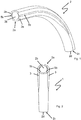
- FIG. 1 shows a curved cannula tube 2 of a tracheostomy tube 1 according to the invention according to a first embodiment without profile elements.
- the cannula tube 2 is made of plastic and has a proximal end 2a with a proximal opening 2b and a distal end 2c with a distal opening 2d. Over part of its outside, the cannula tube 2 has two recessed areas with reduced wall thickness, each of which defines a recess 2e extending in the axial direction.
- the recesses 2e are arranged diametrically on opposite sides of the cannula tube 2.
- the recesses 2e extend from the proximal end 2a of the cannula tube 2 in the axial direction of the cannula tube 2.
- the recesses 2e end at a distance in front of the distal end 2b of the cannula tube 2.
- a suitably shaped profile element 3 can be inserted into each of the recesses 2e, as shown in FIG Figure 2 and more in detail in Figure 3a-c is shown in sections.
- Each profile element 3 has two grooves 3 a, which extend in the axial direction of the tracheostomy tube 1.
- the grooves 3a are arranged between the profile element 3 and the cannula tube 2, more precisely the base of the recess (s).
- the grooves 3 a face the cannula tube 2 and are covered by a surface section of the cannula tube 2 facing the respective profile element 3.
- the grooves 3a and the respective facing surfaces of the cannula tube 2 delimit the inner cross-section of the separate lines 4, which are consequently formed between facing surfaces of the profile element 3 and the recess 2e.
- Two of the total of four lines 4 shown have a larger internal cross-section than the other two lines 4.
- the lines 4 with a larger hydraulic cross-section are preferably used for the passage of liquid and the lines 4 with a smaller cross section are preferably used for the passage of gas.
- One of the lines 4 can be connected to a cuff so that it can be filled by means of a fluid supplied through the lines 4.
- Each of the profile elements 3 can be locked in one of the recesses 2e with locking means 5.
- the profile elements 3 have a latching receptacle 5a into which a latching lug 5b arranged on the cannula tube 2 in the recess 2e engages.
- the profile elements 3 are glued to the cannula tube 2. As a result of the gluing, the profile elements 3 are not only permanently connected to the cannula tube 2, but the lines 4 are also additionally sealed.
- the cannula tube 2 and the profile elements 3 are made of plastic, the plastic of the cannula tube 2 being softer than the plastic of the profile elements 3. Inserted into the recesses 2e of the cannula tube 2, the profile elements 3 stabilize the tracheostomy tube 1 and prevent unwanted kinking of the relatively soft cannula tube 2, which could otherwise block the lines 4 or the central lumen for the passage of breathing gas.
- the recesses 2e and the profile elements 3 are therefore arranged on opposite sides of the cannula tube 2 in a mirror image with respect to the plane defined by the arc of curvature of the central axis of the lumen.
- the profile elements 3 and the recesses 2e of the cannula tube 2 are designed such that the profile elements 3 inserted into the recesses 2e terminate with the outer surface of the cannula tube 2 and form an essentially closed outer contour.
- the profile elements 3 have a cylindrical outer surface which, together with the outer surface of the cannula tube 2c, form a circular outer contour of the tracheostomy tube 1.
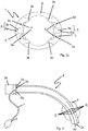
- FIG 3a is the proximal end 2a of the tracheostomy tube 1 from the Figures 1 and 2 shown in a perspective detailed view.
- the inner wall of the cannula tube 2 has at least one (or preferably several diametrically opposite) sliding section 3b, which extends in the axial direction and is partially received in a slot or groove-like wall recess of the cannula tube 2 and partially into the central lumen of the cannula tube 2 extends and by 0.1 mm to 0.5 mm, measured from the inner wall of the cannula tube 2, protrudes into this.
- the sliding section is formed in one piece with the profile element and extends through a slot-shaped opening extending in the axial direction of the cannula tube 2.
- the slide sections 3b which preferably run on diametrically opposite sides, each have a slide-on bevel 3c at their ends.
- the imaginary center lines of the profile elements 3 arranged on opposite sides of the cannula tube 2 are at 90 ° to 270 °.
- the total of four sliding sections 3b of the two profile elements 3 are arranged at 45 °, 135 °, 225 ° and 315 °.
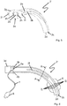
- FIG. 4 a further embodiment of a tracheostomy tube 1 according to the invention is shown, wherein in FIG Figure 5 the associated cannula tube 2 'is shown without profile elements 3.
- the cannula tube 2 ' has two regions with reduced wall thickness, recessed in cross section over part of its circumference on its outside, each defining a recess 2e extending in the axial direction.
- the profile elements 3 and the recesses 2c of the cannula tube 2 ' extend from the proximal end 2a to the distal end 2c of the cannula tube 2'.
- the cannula tube 2 ' has a conical outer cross section tapering in the direction of the distal end 2c.
- the proximal end 2a of the cannula tube 2 ' has a cannula shield 2g which is formed as one piece together with the cannula tube 2'.
- the cannula tube 2 'and the cannula shield 2g are made of a softer plastic than the profile elements 3, which in comparison are made of a harder plastic.
- the cannula shield 2g additionally has two openings 2i for the attachment of a cannula strap and two lateral openings 2h which are arranged to the side of the proximal opening 2b of the cannula tube 2.
- a profile element 3 can be passed through each of the lateral openings 2h from the proximal direction in such a way that the profile elements 3 guided through can be introduced into the recesses 2e of the cannula tube 2 adjoining the openings 2h.
- a connector 3d which is manufactured together with the profile elements 3 as one piece, is in engagement with the proximal opening 2b of the cannula tube 2.
- the recesses 2e have a locking lug 5b which extends in the axial direction of the cannula tube 2 '.
- the latching lug 5b can be brought into engagement with a latching lug receptacle 5a which is arranged on the inside of the profile elements 3.
- the profile elements 3 each have a groove 3a which extend in the axial direction of the profile element 3. If the profile elements 3 are fastened in the recesses 2e of the cannula tube 2 ', the grooves 3a together with the surface of the cannula tube 2' facing the respective profile element 3 delimit the inner cross-section of a line 4.
- One or more of the separate lines 4 are used for suctioning off Secretion, the profile elements 3 having openings for this purpose, which are connected to the lines 4.
- One or more lines 4 are connected to a cuff 6 and via a filling hose 7 to a filling valve 8. With the filling valve 8, fluid can be applied to the cuff 6 via the filling hose 7 and the line 4, or a fluid can be discharged from the cuff 6.
- the cannula tube 2 ' has a plurality of recesses 2j distributed in the circumferential direction.
- the recesses 2j increase the flexibility of the cannula tube 2 '.
- the Figures 6 and 7th show a further embodiment of a tracheostomy tube 1 according to the present invention, wherein the Figure 6 a partially broken away side view and the Figure 7 a cross section along the in the Figure 6 show section line AA shown.
- the ones in the Figures 6 and 7th The embodiment shown differs from the embodiments of FIG Figures 1 to 5 in the design of the profile element and its connection with the cannula tube 2 ′′.
- the cannula tube 2 ′′ of the tracheal cannula 1 ′′ is made of plastic and has a proximal end 2a with a proximal opening 2b, a distal end 2c with a distal opening 2d and four separate lines 4 extending in the axial direction of the cannula tube 2 ′′ two of the four lines 4 are formed between the mutually facing surfaces of a profile element 3 and a recess 2e in the cannula tube 2 ′′.
- the two profile elements 3 are arranged diametrically on opposite sides of the cannula tube 2 ′′ and extend in the axial direction of the cannula tube 2 ′′.
- the cannula tube 2 ′′ is curved, with two recesses 2e separated by a web 2f for receiving a branch of the profile elements 3 separated in the region of the web 2f in the region of the curve. Accordingly, each of the profile elements 3 has a complementary recess 3e for receiving the Web 2f.
- the web 2f is made of a plastic that is softer than the profile elements 3. In this way, the webs increase the flexibility of the cannula tube 2 ′′ Area of curvature, while the profile elements 3 still sufficiently prevent the cannula tube 2 ′′ from narrowing by kinking.
- a plurality of recesses 2j are arranged in a peripheral section of the cannula tube 2 ′′, which is covered by a cuff 6 arranged on the cannula tube.
Landscapes
- Health & Medical Sciences (AREA)
- Pulmonology (AREA)
- Emergency Medicine (AREA)
- Engineering & Computer Science (AREA)
- Anesthesiology (AREA)
- Biomedical Technology (AREA)
- Heart & Thoracic Surgery (AREA)
- Hematology (AREA)
- Life Sciences & Earth Sciences (AREA)
- Animal Behavior & Ethology (AREA)
- General Health & Medical Sciences (AREA)
- Public Health (AREA)
- Veterinary Medicine (AREA)
- Prostheses (AREA)
- External Artificial Organs (AREA)
Description
- Die vorliegende Erfindung betrifft eine Trachealkanüle mit einer integrierten Leitung. Derartige Trachealkanülen auf welche sich die vorliegende Erfindung bezieht, insbesondere Tracheostomiekanülen oder Endotrachealtuben, haben ein Kanülenrohr aus Kunststoff, welches ein proximales Ende mit einer proximalen Öffnung, ein distales Ende mit einer distalen Öffnung und mindestens eine sich in axialer Richtung des Kanülenrohrs parallel zu diesem erstreckende, separate Leitung aufweist. Ein entsprechendes Beispiel zeigt die
DE 197 34 821 A1 . - Trachealkanülen werden in die Trachea eines Patienten eingeführt, um den Patienten mit Luft bzw. Atemgas zu versorgen. Das proximale Ende der Trachealkanüle ist außerhalb des Patienten mit einer Beatmungsvorrichtung verbindbar, während das distale Ende der Trachealkanüle in die Trachea einführbar ist. Das die zwei Enden verbindende Kanülenrohr dient mit seinem zentralen Lumen der Hindurchleitung von Atemgas.
- Die separate Leitung ist beispielsweise für das Befüllen eines Cuffs mit Luft mit dem Cuff verbindbar oder auch zum Absaugen von Sekret nutzbar. Die Leitung soll das Lumen der Trachealkanüle möglichst nicht verkleinern, und ist deshalb oft unmittelbar auf die äußere Oberfläche des Kanülenrohres aufgebracht, beispielsweise mit dem Kanülenrohr verklebt oder verschweißt. Allerdings kann eine auf der Außenseite aufgebrachte Leitung ein Einführen der Trachealkanüle in die Trachea zusätzlich erschweren. Gemäß der
DE 197 34 821 A1 derselben Anmelderin ist deshalb eine solche Leitung in die Wand des Kanülenrohrs integriert. - Die
US 5,647,358 beschreibt eine inter vivo dehnbare Röhre, konkret eine Trachealkanüle, die in Längsrichtung geschlitzt ist, wobei der geschlitzte Bereich mindestens ein im Querschnitt in etwa H-förmiges Profilelement aufweist, welches bezüglich des Außenumfanges der Kanüle verjüngte Randabschnitte beiderseits des Schlitzes umgreift, wobei die verjüngte Randabschnitte beiderseits des Schlitzes in dem H-förmigen Profilelement in Umfangsrichtung verschiebbar sind. - Dabei wird zwischen dem zentralen Quersteg des H-förmigen Profils und dem diesem Quersteg zugewandten Rand der verjüngten Bereiche ein Dehnungsvolumen gebildet, welches durch eine im Inneren der Kanülenwand verlaufende Leitung befüllbar ist. Durch Befüllen der Leitung wird dieses Dehnungsvolumen gefüllt und drückt die beiderseits des Schlitzes in dem H-Profil aufgenommenen Randabschnitte des Kanülenrohres in Umfangsrichtung auseinander. Hierdurch weitet sich der Umfang und der Durchmesser der Trachealkanüle.
- Trachealkanülen mit einem Kanülenrohr aus Kunststoff werden zumeist entweder mittels Extrusion- oder Spritzgussverfahren hergestellt. Kanülenrohre mit einem konischen Innen- und/oder Außendurchmesser und/oder mit einer vorgegebenen Krümmung können allerdings nicht mit der notwendigen Reproduzierbarkeit mittels eines Extrusionsverfahrens hergestellt werden. In einem Spitzgussverfahren können im Gegensatz zu einem Extrusionsverfahren keine Leitungen in die Wand des Kanülenrohrs eingeformt werden.
- Vor diesem Hintergrund ist es eine Aufgabe der vorliegenden Erfindung eine einfach herstellbare Trachealkanüle mit mindestens einer integrierten Leitung bereitzustellen.
- Erfindungsgemäß wird die Aufgabe durch eine Trachealkanüle gemäß der angehängtenAnsprüche definiert.
- Die Erfindung betrifft darüber hinaus ein Verfahren zur Herstellung der erfindungsgemäßen Trachealkanüle, wobei zunächst ein Kanülenrohr und ein Profilelement als zwei getrennte Komponenten der Trachealkanüle bereitgestellt werden. Das Kanülenrohr ist aus einem weicheren Kunststoff hergestellt als das Profilelement und hat eine entlang mindestens eines Umfangsabschnittes rückspringende Außenwand mit einer entsprechend verringerten Wandstärke, wodurch eine Aussparung auf der Außenseite des Kanülenrohrs definiert ist (Vorzugsweise über seitliche Hinterschnitte (0,1-1 mm) gebildete Taschen, wie bei einem Clip-Verschluss). Nach deren Bereitstellung wird das Profilelement in der Aussparung auf der Außenseite des Kanülenrohrs kraft- und/oder formschlüssig angeordnet, sodass in dem Fügebereich zwischen dem Profilelement und dem Kanülenrohr ein Hohlraum bereitgestellt wird, der sich in axialer Richtung der Trachealkanüle erstreckt und die Leitung bildet. Anschließend werden das Profilelement und das Kanülenrohr dauerhaft miteinander verbunden, vorzugsweise durch Verkleben oder Verschweißen. Das erfindungsgemäße Verfahren gliedert sich demnach in die Schritte:
- Bereitstellen des Kanülenrohrs,
- Bereitstellen des mindestens einen Profilelements,
- kraft- und/oder formschlüssiges Anordnen des zumindest einen Profilelements in der Aussparung auf der Außenseite des Kanülenrohrs, und
- dichtes Verbinden des zumindest einen Profilelements mit der Außenfläche des Kanülenrohrs über die axiale Länge des Profilelementes hinweg.
- Die die Aussparung definierenden Flächen werden dabei als Teil der Außenfläche des Kanülenrohrs angesehen.
- Da das Profilelement aus einem härteren Kunststoff hergestellt ist als das Kanülenrohr, stabilisiert das Profilelement das Kanülenrohr und verhindert insbesondere, dass die in dem Fügebereich zwischen dem Profilelement und dem Kanülenrohr angeordnete Leitung oder das zentrale Lumen zum Hindurchführen von Atemgas durch das Kanülenrohr durch ein Verbiegen des Kanülenrohrs weitgehend verschlossen wird. Das Kanülenrohr selbst kann dann aus einem relativ weichen Kunststoff hergestellt werden, der ohne Versteifung durch das erfindungsgemäße Profilelement eher nicht verwendet werden würde. Beispielsweise weist in einer Ausführungsform der Kunststoff des Kanülenrohrs eine Shore-A-Härte in einem Bereich von 40 bis 90, vorzugsweise eine Shore-A-Härte in einem Bereich von 70 bis 80, und der Kunststoff des Profilelements vorzugsweise eine Shore-Härte in einem Bereich von A90 bis D70 auf.
- Die in dem Fügebereich zwischen Profilelement und Kanülenrohr angeordnete Leitung dient der Hindurchleitung eines Fluids. Beispielsweise ist mit der Leitung ein Cuff verbindbar, wobei der Cuff durch ein durch die Leitung hindurchgeführtes Fluid befüllbar ist und der Cuff auch über die Leitung entleert werden kann. Es kann auch eine zweite Leitung parallel zu der ersten Leitung vorgesehen sein, wobei über die erste Leitung ein Cuff befüllbar und über die zweite Leitung ein Fluid abgesaugt und/oder ein Spülfluid zugeführt werden kann. Insbesondere können bei Bereitstellung von zwei oder mehr Leitungen eine Leitung für die Zufuhr eines Fluids und eine andere gleichzeitig zur Absaugung des Fluids verwendet werden. Des Weiteren ist auch eine Leitung zur Zuführung von Luft in den subglottischen Bereich denkbar, die den Patienten bei der Phonation unterstützt.
- In einer Ausführungsform wird der den Innenquerschnitt der Leitung begrenzende und dem Kanülenrohr zugewandte Flächenabschnitt des Profilelementes durch eine Nut gebildet, die sich in Längsrichtung entlang des Profilelementes erstreckt, und/oder der den Innenquerschnitt der Leitung begrenzende und dem Profilelement zugewandte Flächenabschnitt des Kanülenrohrs ist als Nut ausgebildet. Vorzugsweise hat die Nut ein U-Profil. Sind beide den Innenquerschnitt der Leitung begrenzende Flächenabschnitte Nutabschnitte, so sind diese derart zueinander ausgerichtet, dass die zwei Nutabschnitte einen geschlossenen, fluiddichten Innenquerschnitt bilden. Weist nur einer der die Leitung begrenzenden Flächenabschnitte des Profilelementes oder des Kanülenrohrs eine Nut auf, deckt der entsprechend andere, nicht-nutförmige Flächenabschnitt die Nut ab. Auf diese Weise bildet der nicht-nutförmige und den Innenquerschnitt der Leitung begrenzende Flächenabschnitt eine Abdeckung für die Nut. Bei dieser Ausführungsform ist eine exakte Ausrichtung der Flächenabschnitte von Profilelement und Aussparung für den Erhalt einer dichten Leitung weniger kritisch. Herstellungsbedingte Abweichungen bei der Positionierung der Nut sind tolerierbar. Damit der Außenquerschnitt der Trachealkanüle klein und der Innendurchmesser des zentralen Lumens des Kanülenrohrs für die Hindurchleitung von Atemgas groß gehalten werden kann, ist erfindungsgemäß in dem Fügebereich zwischen dem Kanülenrohr und dem Profilelement zumindest eine weitere sich in axialer Richtung erstreckende Leitung angeordnet, die einen Innenquerschnitt aufweist, der durch einen dem Kanülenrohr zugewandten Flächenabschnitt des Profilelementes und einen dem Profilelement zugewandten Flächenabschnitt des Kanülenrohrs begrenzt ist. Der Innenquerschnitt der mindestens zwei Leitungen kann klein gehalten werden, wenn diese zusammen dem gleichen Verwendungszweck dienen. Beispielsweise können die mindestens zwei Leitungen zum Befüllen mit einem Cuff verbunden sein. Das Gesamtfördervolumen verteilt sich auf die Anzahl der verwendeten Leitungen, deren Einzelinnenquerschnitt entsprechend klein ausgeführt sein kann. Die zumindest zwei Leitungen können aber auch für unterschiedliche Zwecke verwendet werden. Beispielsweise können eine Leitung mit einem Cuff und eine weitere Leitung mit einer Absaugvorrichtung verbunden sein.
- Vorzugsweise hat die eine Leitung oder haben die zumindest zwei oder mehreren Leitungen einen hydraulischen Durchmesser, der vorzugsweise ausgewählt ist aus den Bereichen 1 mm bis 4 mm oder 0,3 mm bis 1 mm. Eine Leitung mit einem hydraulischen Durchmesser in dem Bereich 1 mm bis 4 mm ist insbesondere für die Durchleitung von Flüssigkeit geeignet, während eine Leitung mit einem hydraulischen Durchmesser in dem Bereich von 0,3 mm bis 1 mm für die Durchleitung von Gas geeignet ist.
- In einer Ausführungsform bilden die Außenfläche des Profilelements und die Außenfläche des Kanülenrohrs gemeinsam eine geschlossene Außenkontur, vorzugsweise eine Kreisform, oder eine elliptische Form, wobei das Profilelement in einer entsprechenden Aussparung an der Außenfläche des Kanülenrohrs angeordnet ist. Die gemeinsame, geschlossene Außenkontur weist keine Kanten, Ecken oder Vorsprünge auf, die die Trachea oder ein Tracheostoma beim Einführen der Trachealkanüle beschädigen könnten. Ein in einer Aussparung abschnittsweise aufgenommenes Profilelement ist teilweise in den Kunststoff des Kanülenrohrs eingebettet, sodass der Fügebereich zwischen dem Profilelement und dem Kanülenrohr im Wesentlichen innerhalb der einhüllenden Außenkontur des Kanülenrohres angeordnet ist. Der Fügebereich ist weitestgehend durch den ihn umgebenden Kunststoff geschützt.
- Um eine Positionierung und Ausrichtung des Profilelementes relativ zu dem Kanülenrohr bei der Herstellung der Trachealkanüle zu vereinfachen, und um insbesondere ein nachträgliches Anbringen des Profilelementes ohne weitere Spannelemente zu ermöglichen, die das Profilelement in der ausgewählten Position und Ausrichtung relativ zu dem Kanülenrohr halten, sind in einer Ausführungsform das Profilelement und das Kanülenrohr formschlüssig und/oder kraftschlüssig miteinander verbunden, vorzugsweise miteinander verrastet. Das Profilelement und das Kanülenrohr weisen einander zugewandte Befestigungsmittel auf, die miteinander in Eingriff bringbar sind. Nach dem Bereitstellen des Profilelementes und des Kanülenrohrs, wird das Profilelement zunächst kraft- und/oder formschlüssig an dem Kanülenrohr befestigt. Die Befestigungsmittel des Kanülenrohrs und des Profilelementes werden miteinander in Eingriff gebracht, sodass das Profilelement an dem Kanülenrohr in einer durch die Befestigungsmittel vorgegebenen Position und Orientierung befestigt ist. Sind die Befestigungsmittel Rastmittel, weist also das Profilelement und das Kanülenrohr miteinander in Eingriff bringbare Rastnasen und Rastaufnahmen auf, kann das Profilelement mit dem Kanülenrohr verrastet werden. Anschließend kann das Profilelement an dem Kanülenrohr dauerhaft befestigt werden. Beispielsweise kann das Profilelement an dem Kanülenrohr angeschweißt, verklebt oder angespritzt werden. Durch das Anbringen des Profilelements an dem Kanülenrohr wird die zusätzliche Leitung abgedichtet.
- In manchen Fällen ist es wünschenswert, eine Tracheostomiekanüle in Form einer Kombination aus einer Außen- und einer Innenkanüle zu verwenden. Um das Einführen einer Innenkanüle in das erfindungsgemäße Kanülenrohr zu vereinfachen, weist in einer Ausführungsform die Innenwand des Kanülenrohres einen aus einem härteren Kunststoff hergestellten sich in axialer Richtung des Kanülenrohrs erstreckenden Gleitabschnitt auf, der zu einem Teil in einer Aussparung der Wand des Kanülenrohres angeordnet ist und in das zentrale Lumen des Kanülenrohrs und, von den Innenwand desselben gemessen, um vorzugsweise 0,1 mm bis 0,5 mm, hineinragt. Der weichere Kunststoff des Kanülenrohres hat einen höheren Reibungskoeffizienten als der im Vergleich dazu härtere Kunststoff des Profilelements. Auf einem in das Lumen des Kanülenrohrs eingeführten Gleitabschnitt, der aus dem Kunststoff des Profilelements hergestellt ist, kann daher eine Innenkanüle oder ein Absaugschlauch leichter gleiten und durch das Kanülenrohr eingeführt werden. In einer Ausführungsform weist die Innenwand des Kanülenrohrs eine Mehrzahl von Gleitabschnitten, vorzugsweise zwei, drei oder vier Gleitabschnitte auf.
- In weiterer Ausgestaltung dieser Ausführungsform weist das Kanülenrohr im Bereich der Aussparung einen schlitzförmigen Durchbruch auf, während das Profilelement an entsprechender Position einen sich in axialer Richtung des Kanülenrohrs erstreckenden Gleitabschnitt hat, der mit dem Profilabschnitt einstückig ausgebildet ist und durch einen Schlitz in der Wand des Kanülenrohrs hindurchgeführt ist und etwas in das zentrale Lumen des Kanülenrohrs, wiederum um vorzugsweise 0,1 mm bis 0,5 mm, hineinragt.
- In einer weiteren Ausführungsform weist der in das zentrale Lumen des Kanülenrohrs hineinragende Gleitabschnitt eine Aufgleitschräge auf. Die Aufgleitschräge oder Fase verhindert, dass eine in das Kanülenrohr eingeführte Innenkanüle oder ein Absaugschlauch an der in das Lumen hineinragenden Gleitschiene beim Einführen hängenbleibt.
- Damit die Trachealkanüle bei einer Untersuchung in einem in eine Trachea eingeführten Zustand bei der Verwendung bildgebender Verfahren gut sichtbar ist, weist in einer Ausführungsform das Kanülenrohr und/oder das Profilelement ein Kontrastmittel für ein bildgebendes Verfahren, vorzugsweise für die Röntgendiagnostik, Magnetresonanztomographie oder Sonografie, auf.
- In einer Ausführungsform weist das Profilelement einen Konnektor zum Anschließen an eine Beatmungsvorrichtung auf, wobei vorzugsweise das Profilelement und der Konnektor einstückig aus demselben Kunststoff gefertigt sind. Der Konnektor dient dem Anschluss an eine Beatmungsvorrichtung und ist demnach an dem proximalen Ende des Kanülenrohrs zum Verbinden der proximalen Öffnung des Kanülenrohrs mit einer Beatmungsvorrichtung angeordnet. Vorzugsweise weist der Konnektor einen konischen Abschnitt auf, der abschnittsweise in die proximale Öffnung des Kanülenrohrs einsteckbar ist und mit der proximalen Öffnung dicht abschließt. Auf diese Weise kann der Konnektor in die proximale Öffnung nach Art einer Presspassung eingebracht werden. Der Konnektor kann in das Profilelement übergehen, welches sich von dem Konnektor in die Richtung des distalen Endes des Kanülenrohrs erstreckt. Die Presspassung des Konnektors unterstützt die Befestigung des Profilelementes an dem Kanülenrohr und umgekehrt.
- In einer Ausführungsform weist das Kanülenrohr auf seiner Außenfläche ein zweites, sich in axialer Richtung erstreckendes Profilelement auf, wobei in dem Fügebereich zwischen dem Profilelement und dem Kanülenrohr zumindest eine weitere, sich in axialer Richtung erstreckende Leitung angeordnet ist, wobei das zweite Profilelement und/oder die zumindest eine weitere Leitung entsprechend dem zuvor beschriebenen Profilelement oder der Leitung ausgestaltet sind.
- Vorzugsweise sind die Profilelemente auf gegenüberliegenden Seiten des Umfangs des Kanülenrohrs und spiegelbildlich bezüglich einer Ebene angeordnet, welche die Lumenachse enthält. Die aus einem im Vergleich zu dem Kunststoff des Kanülenrohres härteren Kunststoff gefertigten Profilelemente stabilisieren das Kanülenrohr.
- Ist in einer Ausführungsform das Kanülenrohr in einer Ebene gebogen, verläuft eine zentrale Achse des Lumens der Kanüle um einen von 0° verschiedenen Winkel in einem in einer Ebene liegenden Bogen. Vorzugsweise beträgt der Biegewinkel etwa 90°. Bei einer solchen Ausführungsform sind zwei Profilelemente vorzugsweise auf diametral gegenüberliegenden Seiten des Kanülenrohrs und mit demselben Radius gekrümmt in zwei parallelen Ebenen beiderseits und spiegelbildlich bezüglich der durch den Krümmungsbogen der Achse des Lumens definierten Ebene angeordnet.
- In einer Ausführungsform weisen die sich in axialer Richtung erstreckende Aussparung zur mindestens teilweisen Aufnahme eines passend geformten Profilelementes und das Profilelement komplementär zueinander angeordnete Vorsprünge und Ausnehmungen oder Vertiefungen auf. Vorzugsweise weist die Aussparung einen sich in axialer Richtung erstreckenden, vorspringenden Steg und das Profilelement eine sich entsprechend in axiale Richtung erstreckende Nut zur Aufnahme des Stegs auf. Die in der Aussparung angeordneten Vorsprünge des Kanülenrohrs sind, wie das Kanülenrohr selbst, aus einem im Vergleich zu dem Kunststoff des Profilelementes weicheren Kunststoff hergestellt. Ist das Kanülenrohr in einer Ebene gebogen, sind der sich axial erstreckende Steg und die sich axial erstreckende Ausnehmung oder Vertiefung in dem Bereich des Krümmungsbogens angeordnet. Der aus dem weicheren Kunststoff gefertigte Steg durchdringt das Profilelement in dem Bereich des Krümmungsbogens. Durch die sichere Verbindung mit dem Profilelement wird ein Abknicken des Kanülenrohres verhindert. Es versteht sich, dass der Vorsprung und die Ausnehmung oder Vertiefung andere geometrische Formen, wie beispielsweise Zylinder, Dreiecke, Quader, Rechtecke, aufweisen können. Weist die Trachealkanüle mehre Aussparungen und passende Profileelemente auf, so weisen vorzugsweise jede Aussparung einen Vorsprung und jedes Profilelement eine passende Ausnehmung oder Vertiefung auf.
- Um die Flexibilität des Kanülenrohrs an bestimmten Abschnitten, wie zum Beispiel im Bereich eines Cuffs, zu erhöhen, ist in einer Ausführungsform vorgesehen, dass das Kanülenrohr lokal eine Mehrzahl von Ausnehmungen in der Kanülenwand aufweist. Vorzugsweise ist die Mehrzahl von Ausnehmungen in einem Umfangsabschnitt des Kanülenrohrs angeordnet, der von einem an dem Kanülenrohr angeordneten Cuff abgedeckt ist.
- In einer Ausführungsform nehmen der Innenquerschnitt und/oder der Außenquerschnitt des Kanülenrohrs in Richtung des distalen Endes ab. Das Kanülenrohr weist somit eine konische Innen- und/oder Außenwand auf.
- Das Kanülenrohr einer Ausführungsform weist ein angeformtes Kanülenschild auf, wobei vorzugsweise das Kanülenrohr und das Kanülenschild einstückig aus demselben Kunststoff hergestellt sind. Damit ein mit einem Konnektor verbundenes Profilelement mit der proximal zu dem Kanülenschild angeordneten Öffnung des Kanülenrohrs in Eingriff bringbar ist, und dennoch die Profilelemente sich in die Richtung des distalen Endes der Trachealkanüle erstrecken, weist das Kanülenschild in einer Ausführungsform eine Durchführung für das Profilelement auf.
- Soweit in der vorliegenden Beschreibung, einschließlich der nachfolgenden Figurenbeschreibung Aspekte der Erfindung im Hinblick auf die Trachealkanüle beschrieben wurden, so gelten diese auch für das entsprechende Verfahren zum Herstellen einer solchen Trachealkanüle und umgekehrt.
- Weitere Vorteile, Merkmale und Anwendungsmöglichkeiten der vorliegenden Erfindung werden anhand der vorliegenden Beschreibung einer Ausführungsform und der dazugehörigen Figuren deutlich, wobei gleiche Bezugszeichen auf gleiche Elemente verweisen. Es zeigen:
- Figur 1:
- eine Perspektivansicht auf das Kanülenrohr einer erfindungsgemäßen Ausführungsform einer Trachealkanüle, dargestellt ohne Profilelemente,
- Figur 2:
- eine Ansicht auf das proximale Ende des Kanülenrohrs gemäß der Ausführungsform aus
Figur 1 , dargestellt mit Profilelementen, - Figur 3a:
- eine perspektivische Detailansicht auf das proximale Ende des Kanülenrohrs einer Trachealkanüle gemäß der Ausführungsform aus
Figur 2 , - Figur 3b
- eine Draufsicht auf das proximale Ende des Kanülenrohrs einer Trachealkanüle gemäß der Ausführungsform aus
Figur 3a , - Figur 3c
- einen Querschnitt durch das proximale Ende des Kanülenrohrs einer Trachealkanüle gemäß der der Ausführungsform aus
Figur 3a , - Figur 4:
- eine teilweise weggebrochene Seitenansicht einer Trachealkanüle gemäß einer weiteren Ausführungsform der vorliegenden Erfindung,
- Figur 5:
- eine Perspektivansicht auf das Kanülenrohr der Trachealkanüle aus
Figur 4 , dargestellt ohne Profilelemente und Cuff, - Figur 6:
- eine teilweise weggebrochene Seitenansicht einer Trachealkanüle gemäß einer weiteren Ausführungsform der vorliegenden Erfindung, und
- Figur 7:
- ein Querschnitt durch die Trachealkanüle entlang der Schnittlinie A-A gemäß
Figur 6 . - In der
Figur 1 ist ein gebogenes Kanülenrohr 2 einer erfindungsgemäßen Trachealkanüle 1 gemäß einer ersten Ausführungsform ohne Profilelemente dargestellt. Das Kanülenrohr 2 ist aus Kunststoff gefertigt und weist ein proximales Ende 2a mit einer proximalen Öffnung 2b sowie ein distales Ende 2c mit einer distalen Öffnung 2d auf. Über einen Teil seiner Außenseite hat das Kanülenrohr 2 zwei rückspringende Bereiche mit reduzierter Wandstärke, die jeweils eine sich in axialer Richtung erstreckende Aussparung 2e definieren. Die Aussparungen 2e sind diametral auf gegenüberliegenden Seiten des Kanülenrohrs 2 angeordnet. Die Aussparungen 2e erstrecken sich von dem proximalen Ende 2a des Kanülenrohres 2 in axialer Richtung des Kanülenrohrs 2. Die Aussparungen 2e enden im Abstand vor dem distalen Ende 2b des Kanülenrohrs 2. - In jede der Aussparungen 2e ist ein passend geformtes Profilelement 3 einsetzbar, wie es in der
Figur 2 und noch detaillierter inFigur 3a-c abschnittsweise dargestellt ist. Jedes Profilelement 3 hat zwei Nuten 3a, die sich in axialer Richtung der Trachealkanüle 1 erstrecken. In einem Zustand, in dem das Profilelement 3 in die Aussparung 2e des Kanülenrohrs 2 eingesetzt ist, sind die Nuten 3a zwischen dem Profilelement 3 und dem Kanülenrohr 2, genauer gesagt dem Grund der Aussparung(en), angeordnet. Die Nuten 3a sind dem Kanülenrohr 2 zugewandt und werden von einem dem jeweiligen Profilelement 3 zugewandten Flächenabschnitt des Kanülenrohrs 2 abgedeckt. Die Nuten 3a und die ihr jeweils zugewandten Flächen des Kanülenrohrs 2 begrenzen den Innenquerschnitt der separaten Leitungen 4, die folglich zwischen einander zugewandten Flächen des Profilelementes 3 und der Aussparung 2e gebildet werden. Zwei der insgesamt vier gezeigten Leitungen 4 haben einen größeren Innenquerschnitt als die übrigen zwei Leitungen 4. Die Leitungen 4 mit einem größeren hydraulischen Querschnitt werden vorzugsweise für die Durchleitung von Flüssigkeit und die Leitungen 4 mit einem kleineren Querschnitt werden vorzugsweise für die Durchleitung von Gas verwendet. Eine der Leitungen 4 ist mit einem Cuff verbindbar, sodass dieser mittels eines durch die Leitungen 4 zugeführten Fluids befüllbar ist. - Jedes der Profilelemente 3 ist in je einer der Aussparungen 2e mit Rastmitteln 5 verrastbar. Die Profilelemente 3 weisen eine Rastaufnahme 5a auf, in die ein an dem Kanülenrohr 2 in der Aussparung 2e angeordnete Rastnase 5b eingreift. Nach dem Anbringen der Profilelemente 3 in den Aussparungen 2e werden die Profilelemente 3 an das Kanülenrohr 2 geklebt. Durch das Verkleben sind die Profilelemente 3 nicht nur dauerhaft mit dem Kanülenrohr 2 verbunden, sondern es werden dadurch auch die Leitungen 4 zusätzlich abgedichtet.
- Das Kanülenrohr 2 und die Profilelemente 3 sind aus Kunststoff hergestellt, wobei der Kunststoff des Kanülenrohrs 2 weicher als der Kunststoff der Profilelemente 3 ist. In die Aussparungen 2e des Kanülenrohrs 2 eingesetzt, stabilisieren die Profilelemente 3 die Trachealkanüle 1 und verhindern ein ungewolltes Abknicken des relativ weichen Kanülenrohrs 2, was ansonsten die Leitungen 4 oder das zentrale Lumen zum Hindurchführen von Atemgas blockieren könnte. Die Aussparungen 2e und die Profilelemente 3 sind daher auf gegenüberliegenden Seiten des Kanülenrohrs 2 spiegelbildlich bezüglich der durch den Krümmungsbogen der zentralen Achse des Lumens definierten Ebene angeordnet.
- Die Profilelemente 3 und die Aussparungen 2e des Kanülenrohrs 2 sind derart ausgestaltet, dass die in die Aussparungen 2e eingesetzten Profilelemente 3 mit der Außenfläche des Kanülenrohrs 2 abschließen und eine im Wesentlichen geschlossene Außenkontur bilden. Die Profilelemente 3 haben eine zylindrische Außenfläche, die zusammen mit der Außenfläche des Kanülenrohrs 2c eine kreisförmige Außenkontur der Trachealkanüle 1 bilden.
- In der
Figur 3a ist das proximale Ende 2a der Trachealkanüle 1 aus denFiguren 1 und 2 in einer perspektivischen Detailansicht gezeigt. Die in die Aussparungen 2e des Kanülenrohrs 2 eingesetzten Profilelemente 3 und die Außenfläche des Kanülenrohrs 2 bilden gemeinsam eine elliptische Außenkontur. - Die Innenwand des Kanülenrohres 2 weist mindestens einen (oder vorzugsweise mehrere diametral gegenüberliegend angeordnete) Gleitabschnitt 3b auf, der sich in axialer Richtung erstreckt und teilweise in einer schlitz- oder nutartigen Wandaussparung des Kanülenrohres 2 aufgenommen ist und sich teilweise in das zentrale Lumen des Kanülenrohrs 2 erstreckt und um 0,1 mm bis 0,5 mm, gemessen von der Innenwand des Kanülenrohrs 2, in dieses hineinragt. In einer hier nicht dargestellten Variante ist der Gleitabschnitt einstückig mit dem Profilelement ausgebildet und erstreckt sich durch eine sich in axialer Richtung des Kanülenrohrs 2 erstreckende, schlitzförmige Durchbrechung. Damit eine Innenkanüle leichter in das zentrale Lumen des Kanülenrohrs 2 eingeführt werden und auf dem Gleitabschnitt 3b gleiten kann, weisen die vorzugsweise auf diametral gegenüberliegenden Seiten verlaufenden Gleitabschnitte 3b an ihren Enden je eine Aufgleitschräge 3c auf. In einer Draufsicht auf den Querschnitt der Trachealkanüle 1, wie er in der
Figur 3b dargestellt ist, befinden sich die gedachten Mittelinien der auf gegenüberliegenden Seiten des Kanülenrohrs 2 angeordneten Profilelemente 3 auf 90° bis 270°. Die insgesamt vier Gleitabschnitte 3b der zwei Profilelemente 3 sind bei 45°, 135°, 225° und 315° angeordnet. - In der
Figur 3c , die einen Querschnitt durch das proximale Ende 2a der Trachealkanüle 1 aus denFiguren 3a und 3b zeigt, sind die sich durch die Kanülenwand hindurcherstreckenden Gleitabschnitte 3b der in den Aussparungen 2e angeordneten Profilelemente 3 erkennbar. - In der
Figur 4 ist eine weitere Ausführungsform einer erfindungsgemäßen Trachealkanüle 1 gezeigt, wobei in derFigur 5 das dazugehörige Kanülenrohr 2' ohne Profilelemente 3 dargestellt ist. Das Kanülenrohr 2' weist zwei über einen Teil seines Umfangs auf seiner Außenseite im Querschnitt rückspringende Bereiche mit reduzierter Wandstärke auf, die jeweils eine sich in axialer Richtung erstreckende Aussparung 2e definieren. Die Profilelemente 3 und die Aussparungen 2c des Kanülenrohrs 2' erstrecken sich bei dieser Ausführungsform von dem proximalen Ende 2a bis zu dem distalen Ende 2c des Kanülenrohrs 2'. Das Kanülenrohr 2' hat einen konischen, in Richtung des distalen Ende 2c zulaufenden Außenquerschnitt. - Das proximale Ende 2a des Kanülenrohrs 2' weist ein Kanülenschild 2g auf, welches zusammen mit den Kanülenrohr 2' als ein Stück geformt ist. Das Kanülenrohr 2' und das Kanülenschild 2g sind aus einem weicheren Kunststoff gefertigt als die Profilelemente 3, die im Vergleich dazu aus einem härteren Kunststoff hergestellt sind.
- Das Kanülenschild 2g weist zusätzlich zwei Durchbrechungen 2i für die Befestigung eines Kanülenbands sowie zwei seitliche Durchbrechungen 2h auf, die seitlich der proximalen Öffnung 2b des Kanülenrohrs 2 angeordnet sind. Durch jede der seitlichen Durchbrechungen 2h ist aus proximaler Richtung ein Profilelement 3 derart hindurchführbar, dass die hindurchgeführten Profilelemente 3 in die sich an die Durchbrechungen 2h anschließenden Aussparungen 2e des Kanülenrohrs 2 einbringbar sind.
- In einem Zustand in dem die Profilelemente 3 in die Aussparungen 2e des Kanülenrohrs 2 eingebracht sind, steht ein Konnektor 3d, welcher zusammen mit den Profilelementen 3 als ein Stück gefertigt ist, in Eingriff mit der proximalen Öffnung 2b des Kanülenrohrs 2.
- Die Aussparungen 2e weisen eine Rastnase 5b auf, die sich in axialer Richtung des Kanülenrohrs 2' erstreckt. Die Rastnase 5b ist mit einer Rastnasenaufnahme 5a in Eingriff bringbar, welche auf der Innenseite der Profilelemente 3 angeordnet ist. Links und rechts neben der Rastnasenaufnahme 5a weisen die Profilelemente 3 je eine Nut 3a auf, die sich in axialer Richtung des Profilelementes 3 erstrecken. Sind die Profilelemente 3 in den Aussparungen 2e des Kanülenrohrs 2' befestigt, begrenzen die Nuten 3a zusammen mit der dem jeweiligen Profilelement 3 zugewandten Fläche des Kanülenrohr 2' den Innenquerschnitt einer Leitung 4. Eine bzw. auch mehrere der separaten Leitungen 4 dienen dem Absaugen von Sekret, wobei die Profilelemente 3 hierzu Öffnungen aufweisen, die mit den Leitungen 4 verbunden sind. Eine oder weitere Leitungen 4 sind mit einem Cuff 6 und über einen Füllschlauch 7 mit einem Füllventil 8 verbunden. Mit dem Füllventil 8 kann über den Füllschlauch 7 und der Leitung 4 der Cuff 6 mit einem Fluid beaufschlagt oder ein Fluid aus dem Cuff 6 ausgeleitet werden.
- In dem von dem Cuff 6 abgedeckten Abschnitt, weist das Kanülenrohr 2' eine Mehrzahl von in Umfangsrichtung verteilt angeordneten Ausnehmungen 2j auf. Die Ausnehmungen 2j erhöhen die Flexibilität des Kanülenrohrs 2'.
- Die
Figuren 6 und7 zeigen eine weitere Ausführungsform einer Trachealkanüle 1 gemäß der vorliegenden Erfindung, wobei dieFigur 6 eine teilweise weggebrochene Seitenansicht und dieFigur 7 einen Querschnitt entlang der in derFigur 6 gezeigten Schnittlinie A-A zeigen. Die in denFiguren 6 und7 gezeigte Ausführungsform unterscheidet sich von den Ausführungsformen derFiguren 1 bis 5 in der Ausgestaltung des Profilelementes und dessen Verbindung mit dem Kanülenrohr 2". - Das Kanülenrohr 2" der Trachealkanüle 1" ist aus Kunststoff gefertigt und weist ein proximales Ende 2a mit einer proximalen Öffnung 2b, ein distales Ende 2c mit einer distalen Öffnung 2d sowie vier sich in axialer Richtung des Kanülenrohrs 2" erstreckende separate Leitungen 4 auf. Je zwei der vier Leitungen 4 sind zwischen den einander zugewandten Flächen eines Profilelementes 3 und einer Aussparung 2e in dem Kanülenrohr 2" gebildet. Die zwei Profilelemente 3 sind diametral auf gegenüberliegenden Seiten des Kanülenrohrs 2" angeordnet und erstrecken sich in axialer Richtung des Kanülenrohrs 2". Das Kanülenrohr 2" ist gebogen, wobei in dem Bereich des Krümmungsbogens zwei durch einen Steg 2f getrennte Aussparungen 2e zur Aufnahme jeweils eines Zweiges der im Bereich des Steges 2f aufgetrennten Profilelemente 3 . Entsprechend hat jedes der Profilelemente 3 eine komplementär ausgestaltete Ausnehmung 3e zur Aufnahme des Steges 2f.
- Der Steg 2f ist wie das Kanülenrohr 2" aus einem im Vergleich zu den Profilelementen 3 weicheren Kunststoff gefertigt. Auf diese Weise erhöhen die Stege die Flexibilität des Kanülenrohrs 2" in dem Krümmungsbereich, während die Profilelemente 3 nach wie vor ausreichend verhindern, dass das Kanülenrohr 2" sich durch Abknicken verengt.
- Wie die Ausführungsform gemäß
Figur 4 , ist auch bei der Ausführungsform gemäß denFiguren 6 und7 eine Mehrzahl von Ausnehmungen 2j in einem Umfangsabschnitt des Kanülenrohrs 2" angeordnet, der von einem an dem Kanülenrohr angeordneten Cuff 6 abgedeckt ist. - Für Zwecke der ursprünglichen Offenbarung wird darauf hingewiesen, dass sämtliche Merkmale, wie sie sich aus der vorliegenden Beschreibung, den Zeichnungen und den Ansprüchen für einen Fachmann erschließen, auch wenn sie konkret nur im Zusammenhang mit bestimmten weiteren Merkmalen beschrieben wurden, sowohl einzeln als auch in beliebigen Zusammenstellungen mit anderen der hier offenbarten Merkmale oder Merkmalsgruppen kombinierbar sind, soweit dies nicht ausdrücklich ausgeschlossen wurde oder technische Gegebenheiten derartige Kombinationen unmöglich oder sinnlos machen. Auf die umfassende, explizite Darstellung sämtlicher denkbarerer Merkmalskombinationen wird hier nur der Kürze und der Lesbarkeit der Beschreibung wegen verzichtet.
- Während die Erfindung im Detail in den Zeichnungen und der vorangehenden Beschreibung dargestellt und beschreiben wurde, erfolgt diese Darstellung und Beschreibung lediglich beispielhaft und ist nicht als Beschränkung des Schutzbereichs gedacht, so wie er durch die Ansprüche definiert wird.
- Abwandlungen der offenbarten Ausführungsformen sind für den Fachmann aus den Zeichnungen, der Beschreibung und den beigefügten Ansprüchen offensichtlich. In den Ansprüchen schließt das Wort "aufweisen" nicht andere Elemente oder Schritte aus, und der unbestimmte Artikel "eine" oder "ein" schließt eine Mehrzahl nicht aus. Die bloße Tatsache, dass bestimmte Merkmale in unterschiedlichen Ansprüchen beansprucht sind, schließt ihre Kombination nicht aus. Bezugszeichen in den Ansprüchen sind nicht als Beschränkung des Schutzbereichs gedacht.
-
- 1
- Trachealkanüle
- 2, 2', 2"
- Kanülenrohr
- 2a
- proximales Ende
- 2b
- proximale Öffnung
- 2c
- distales Ende
- 2d
- distale Öffnung
- 2e
- Aussparung
- 2f
- stegförmiger Vorsprung
- 2g
- Kanülenschild
- 2h
- seitliche Durchbrechungen
- 2i
- Durchbrechungen für die Befestigung eines Kanülenbands
- 2j
- Ausnehmungen
- 3
- Profilelement
- 3a
- Nut
- 3b
- Gleitabschnitt
- 3c
- Aufgleitschräge
- 3d
- Konnektor
- 3e
- Ausnehmung oder Vertiefung
- 4
- Leitung
- 5
- Befestigungsmittel
- 5a
- Rastnasenaufnahme
- 5b
- Rastnase
- 6
- Blockungsmanschette (Cuff)
- 7
- Füllschlauch
- 8
- Füllventil
Claims (17)
- Trachealkanüle (1), insbesondere Tracheostomiekanüle oder Endotrachealtubus, mit einem Kanülenrohr (2) aus Kunststoff, welches ein proximales Ende (2a) mit einer proximalen Öffnung (2b), ein distales Ende (2c) mit einer distalen Öffnung (2d) und mindestens eine sich in axialer Richtung des Kanülenrohrs (2) erstreckende separate Leitung (4) aufweist, und einem Profilelement (3), das aus einem im Vergleich zu dem Kunststoff des Kanülenrohrs (2) härteren Kunststoff hergestellt ist dadurch gekennzeichnet, dass das Kanülenrohr (2) über einen Teil seines Umfangs auf seiner Außenseite einen im Querschnitt rückspringenden Bereich mit reduzierter Wandstärke aufweist, wodurch eine sich in axialer Richtung erstreckende Aussparung (2e) auf der Außenseite des Kanülenrohrs zur mindestens teilweisen Aufnahme des passend geformten Profilelementes (3) definiert wird, wobei die Leitung (4) zwischen den einander zugewandten Flächen des Profilelementes (3) und der Aussparung dadurch gebildet wird, dass deren Innenquerschnitt durch einen dem Kanülenrohr zugewandten Flächenabschnitt des Profilelementes (3) und einen dem Profilelement zugewandten Flächenabschnitt des Kanülenrohrs begrenzt ist.
- Trachealkanüle (1) nach Anspruch 1, dadurch gekennzeichnet, dass der den Innenquerschnitt der Leitung (4) begrenzende und dem Kanülenrohr (2) zugewandte Flächenabschnitt des Profilelementes (3) durch eine Nut (3a) gebildet ist, die sich in Längsrichtung entlang des Profilelementes (3) erstreckt, und/oder der den Innenquerschnitt der Leitung (4) begrenzende und dem Profilelement (3) zugewandte Flächenabschnitt des Kanülenrohrs (2) ist als Nut (2f) ausgebildet.
- Trachealkanüle (1) nach Anspruch 1 oder 2, dadurch gekennzeichnet, dass zwischen dem Kanülenrohr (2) und dem Profilelement (3) zumindest eine weitere sich in axialer Richtung des Kanülenrohrs (2) erstreckende Leitung (4) ausgebildet ist.
- Trachealkanüle (1) nach einem der Ansprüche 1 bis 3, dadurch gekennzeichnet, dass die mindestens eine Leitung (4) einen hydraulischen Durchmesser im Bereich von 0,3 mm bis 1 mm und/oder dass im Falle mehrerer Leitungen (4) mindestens eine dieser Leitungen einen hydraulischen Durchmesser im Bereich von 1 mm bis 4 mm aufweist.
- Trachealkanüle (1) nach einem der Ansprüche 1 bis 4, dadurch gekennzeichnet, dass die Außenfläche des Profilelements (3) zusammen mit der Außenfläche des Kanülenrohrs (2) eine im wesentlichen geschlossene Außenkontur, vorzugsweise eine Kreisform, Ellipsenform, bildet, wobei das Profilelement (3) in einer entsprechenden Aussparung (2e) in der Außenfläche des Kanülenrohrs (2) angeordnet ist.
- Trachealkanüle (1) nach einem der Ansprüche 1 bis 5, dadurch gekennzeichnet, dass das Profilelement (3) und das Kanülenrohr (2) formschlüssig und/oder kraftschlüssig miteinander verbunden, vorzugsweise miteinander verrastet, sind
- Trachealkanüle (1) nach einem der Ansprüche 1 bis 6, dadurch gekennzeichnet, dass der Kunststoff des Kanülenrohrs (2) eine Shore-A-Härte in einem Bereich von 40 bis 90, vorzugsweise eine Shore-A-Härte in einem Bereich von 70 bis 80, und der Kunststoff des Profilelements (3) vorzugsweise eine Shore-Härte in einem Bereich von A90 bis D70 aufweist.
- Trachealkanüle (1) nach einem der Ansprüche 1 bis 7, dadurch gekennzeichnet, dass an der Innenwand des Kanülenrohres ein aus einem härteren Kunststoff hergestellter sich in axialer Richtung des Kanülenrohrs (2) erstreckender Gleitabschnitt (3b) vorgesehen ist, der zu einem Teil in einer Aussparung in der Wand des Kanülenrohres angeordnet ist und in das zentrale Lumen des Kanülenrohrs (2) und von der Innenwand desselben gemessen um vorzugsweise 0,1 mm bis 0,5 mm, hineinragt
- Trachealkanüle (1) nach Anspruch 8 dadurch gekennzeichnet, dass der Gleitabschnitt (3b) aus einem Stück mit dem Profilelement (3) hergestellt ist und durch eine sich über einen Teil der Länge des Kanülenrohres (2) erstreckende, schlitzförmige Durchbrechung desselben(2) in das zentrale Lumen des Kanülenrohrs (2) hineinragt.
- Trachealkanüle (1) nach Anspruch 8 oder 9, dadurch gekennzeichnet, dass der in das zentrale Lumen des Kanülenrohrs (2) hineinragende Gleitabschnitt (3b) eine Aufgleitschräge (3c) aufweist.
- Trachealkanüle (1) nach einem der Ansprüche 1 bis 10, dadurch gekennzeichnet, dass das Kanülenrohr (2) und/oder das Profilelement (3) ein Kontrastelement für ein bildgebendes Verfahren, vorzugsweise für die Röntgendiagnostik, Magnetresonanztomographie oder Sonografie, aufweist.
- Trachealkanüle (1) nach einem der Ansprüche 1 bis 11, dadurch gekennzeichnet, dass das Profilelement (3) einen Konnektor (3d) zum Anschließen einer Beatmungsvorrichtung aufweist, wobei vorzugsweise das Profilelement (3) und der Konnektor (3c) einstückig aus demselben Kunststoff gefertigt sind.
- Trachealkanüle (1) nach einem der Ansprüche 1 bis 12, dadurch gekennzeichnet, dass das Kanülenrohr (2) auf seiner Außenfläche eine zweite Aussparung mit einem zweiten, sich in axialer Richtung erstreckenden Profilelement (3) aufweist, wobei zwischen dem Profilelement (3) und dem Kanülenrohr (2) zumindest eine weitere, sich axial erstreckende Leitung (4) ausgebildet ist, wobei das zweite Profilelement (2) und/oder die weitere Leitung (4) gemäß einem der vorgenannten Ansprüche ausgestaltet sind.
- Trachealkanüle (1) nach einem der Ansprüche 1 bis 13, dadurch gekennzeichnet, dass die sich in axiale Richtung erstreckende Aussparung (2e) einen Vorsprung, vorzugsweise einen sich axial erstreckenden Steg (2f)" und das in die Aussparung eingesetzte Profilelement (3) eine komplementär zu dem Vorsprung ausgestaltete Ausnehmung (3e) aufweist.
- Trachealkanüle (1) nach einem der Ansprüche 1 bis 14, dadurch gekennzeichnet, dass die Innen- und/oder Außenwand des Kanülenrohrs (2) sich in axialer Richtung vom proximalen zum distalen Ende hin konisch verjüngt.
- Trachealkanüle (1) nach einem der Ansprüche 1 bis 15, dadurch gekennzeichnet, dass das Kanülenrohr (2) ein angeformtes Kanülenschild (2g) aufweist, wobei vorzugsweise das Kanülenschild (2g) und das Kanülenrohr (2) einstückig aus demselben Kunststoff hergestellt sind.
- Verfahren zum Herstellen der Trachealkanüle (1) nach einem der Ansprüche 1 bis 16 mit den Schritten- Bereitstellen eines Kanülenrohrs (2), mit einer entlang mindestens eines Umfangsabschnittes rückspringenden Außenwand und entsprechend verringerter Wandstärke, wodurch eine sich in axialer Richtung erstreckende Aussparung auf der Außenseite des Kanülenrohres definiert wird- Bereitstellen des mindestens einen Profilelements (3),- kraft- und/oder formschlüssiges Anordnen des zumindest einen Profilelements (3) in der Aussparung auf der Außenseite des Kanülenrohrs (2), und- dichtes Verbinden des zumindest einen Profilelements (3) mit der Außenfläche des Kanülenrohrs (2) über die axiale Länge des Profilelementes hinweg.
Applications Claiming Priority (2)
| Application Number | Priority Date | Filing Date | Title |
|---|---|---|---|
| DE102017106750.7A DE102017106750A1 (de) | 2017-03-29 | 2017-03-29 | Trachealkanüle mit einer integrierten Leitung |
| PCT/EP2018/057816 WO2018178098A1 (de) | 2017-03-29 | 2018-03-27 | Trachealkanüle mit einer integrierten leitung |
Publications (2)
| Publication Number | Publication Date |
|---|---|
| EP3600507A1 EP3600507A1 (de) | 2020-02-05 |
| EP3600507B1 true EP3600507B1 (de) | 2021-07-28 |
Family
ID=61911551
Family Applications (1)
| Application Number | Title | Priority Date | Filing Date |
|---|---|---|---|
| EP18716158.3A Active EP3600507B1 (de) | 2017-03-29 | 2018-03-27 | Trachealkanüle mit einer integrierten leitung |
Country Status (3)
| Country | Link |
|---|---|
| EP (1) | EP3600507B1 (de) |
| DE (1) | DE102017106750A1 (de) |
| WO (1) | WO2018178098A1 (de) |
Families Citing this family (3)
| Publication number | Priority date | Publication date | Assignee | Title |
|---|---|---|---|---|
| DE102020115938B4 (de) | 2020-06-17 | 2025-11-06 | Andreas Fahl Medizintechnik-Vertrieb Gmbh | Trachealkanüle |
| US20230248931A1 (en) * | 2020-12-11 | 2023-08-10 | Blake J. Hyde | Irrigating cannula system |
| US11786683B2 (en) * | 2020-12-11 | 2023-10-17 | Blake J. Hyde | Irrigating intraluminal suction inner cannula system |
Family Cites Families (8)
| Publication number | Priority date | Publication date | Assignee | Title |
|---|---|---|---|---|
| DE3522782A1 (de) * | 1985-06-26 | 1987-01-15 | Peter Brehm Chir Mechanik Werk | Doppellumige follikelpunktionskanuele |
| US5360414A (en) * | 1992-10-08 | 1994-11-01 | Yarger Richard J | Tube for draining body cavities, viscera and wounds |
| US5647358A (en) * | 1996-03-20 | 1997-07-15 | Vilasi; Joseph | Expandable inter vivos tube |
| DE19734821A1 (de) | 1997-08-12 | 1999-02-18 | Tracoe Medizine Ges Fuer | Endotracheal- oder Tracheotomietubus |
| CN100341592C (zh) * | 1999-06-08 | 2007-10-10 | 爱德华兹生命科学公司 | 多腔介入装置 |
| US20040255951A1 (en) * | 2003-02-07 | 2004-12-23 | Christopher Grey | Endotrachael tube with suction catheter and system |
| US7921847B2 (en) * | 2005-07-25 | 2011-04-12 | Intubix, Llc | Device and method for placing within a patient an enteral tube after endotracheal intubation |
| DE102008015050A1 (de) * | 2008-03-19 | 2009-09-24 | Tracoe Medical Gmbh | Tracheostomiekanüle aus mindestens zwei verschiedenen Kunststoffen |
-
2017
- 2017-03-29 DE DE102017106750.7A patent/DE102017106750A1/de active Pending
-
2018
- 2018-03-27 EP EP18716158.3A patent/EP3600507B1/de active Active
- 2018-03-27 WO PCT/EP2018/057816 patent/WO2018178098A1/de not_active Ceased
Also Published As
| Publication number | Publication date |
|---|---|
| DE102017106750A1 (de) | 2018-10-04 |
| EP3600507A1 (de) | 2020-02-05 |
| WO2018178098A1 (de) | 2018-10-04 |
Similar Documents
| Publication | Publication Date | Title |
|---|---|---|
| EP0631508B1 (de) | Absaugkatheter | |
| DE69108219T2 (de) | Mehrlumiger Katheter. | |
| EP2349427B1 (de) | Larynxmaske mit oesophagealdurchgang | |
| DE69109268T2 (de) | Zusammengesetzter trachealtubus. | |
| EP0338380B1 (de) | Absaugkatheter zum Einführen in die Luftröhre und das Bronchialsystem | |
| DE69321257T2 (de) | Gebogener koaxial-katheter | |
| DE3789716T2 (de) | Mechanisch verstärkter Tubus für Heilzwecke. | |
| EP3535002B1 (de) | Tracheostomiekanüle | |
| DE2547796A1 (de) | Saugkatheter | |
| DE3521056A1 (de) | Selbstabdichtendes rueckschlag- bzw. absperrventil | |
| WO2009115403A1 (de) | Tracheostomiekanüle aus mindestens zwei verschiedenen kunststoffen | |
| DE2353641A1 (de) | Katheter | |
| WO2018178098A1 (de) | Trachealkanüle mit einer integrierten leitung | |
| DE102009054573A1 (de) | Tracheostomiekanüle mit Fenster | |
| DE102014109001A1 (de) | Trachealbeatmungsvorrichtung | |
| DE112015002454T5 (de) | Katheter, Katheterherstellungsform, und Katheterherstellungsverfahren | |
| DE102013011177A1 (de) | Universell positionierbares Wasserfallensystem für Atemschlauchsysteme | |
| DE10340708A1 (de) | Steckbare Röhrenverbindung | |
| DE1951236B1 (de) | Trachealkanuele | |
| EP2947364A1 (de) | Schlauchverbindungs-vorrichtung und massage-toy mit einer solchen schlauchverbindungs-vorrichtung | |
| EP3787722A1 (de) | Trachealbeatmungsvorrichtung mit einer abdichtung | |
| DE3731590C1 (en) | Medical probe | |
| EP3727538B1 (de) | Tracheaostomiekanüle mit einer phonationsöffnung | |
| DE69220205T2 (de) | Koaxial-Katheter | |
| DE3623367A1 (de) | Kupplungseinrichtung fuer narkose- und beatmungsgeraete |
Legal Events
| Date | Code | Title | Description |
|---|---|---|---|
| STAA | Information on the status of an ep patent application or granted ep patent |
Free format text: STATUS: UNKNOWN |
|
| STAA | Information on the status of an ep patent application or granted ep patent |
Free format text: STATUS: THE INTERNATIONAL PUBLICATION HAS BEEN MADE |
|
| PUAI | Public reference made under article 153(3) epc to a published international application that has entered the european phase |
Free format text: ORIGINAL CODE: 0009012 |
|
| STAA | Information on the status of an ep patent application or granted ep patent |
Free format text: STATUS: REQUEST FOR EXAMINATION WAS MADE |
|
| 17P | Request for examination filed |
Effective date: 20191014 |
|
| AK | Designated contracting states |
Kind code of ref document: A1 Designated state(s): AL AT BE BG CH CY CZ DE DK EE ES FI FR GB GR HR HU IE IS IT LI LT LU LV MC MK MT NL NO PL PT RO RS SE SI SK SM TR |
|
| AX | Request for extension of the european patent |
Extension state: BA ME |
|
| DAV | Request for validation of the european patent (deleted) | ||
| DAX | Request for extension of the european patent (deleted) | ||
| REG | Reference to a national code |
Ref country code: DE Ref legal event code: R079 Ref document number: 502018006315 Country of ref document: DE Free format text: PREVIOUS MAIN CLASS: A61M0016040000 Ipc: B29D0023000000 |
|
| GRAP | Despatch of communication of intention to grant a patent |
Free format text: ORIGINAL CODE: EPIDOSNIGR1 |
|
| STAA | Information on the status of an ep patent application or granted ep patent |
Free format text: STATUS: GRANT OF PATENT IS INTENDED |
|
| RIC1 | Information provided on ipc code assigned before grant |
Ipc: B29D 23/00 20060101AFI20210406BHEP Ipc: A61M 16/04 20060101ALI20210406BHEP |
|
| INTG | Intention to grant announced |
Effective date: 20210507 |
|
| GRAS | Grant fee paid |
Free format text: ORIGINAL CODE: EPIDOSNIGR3 |
|
| GRAA | (expected) grant |
Free format text: ORIGINAL CODE: 0009210 |
|
| STAA | Information on the status of an ep patent application or granted ep patent |
Free format text: STATUS: THE PATENT HAS BEEN GRANTED |
|
| AK | Designated contracting states |
Kind code of ref document: B1 Designated state(s): AL AT BE BG CH CY CZ DE DK EE ES FI FR GB GR HR HU IE IS IT LI LT LU LV MC MK MT NL NO PL PT RO RS SE SI SK SM TR |
|
| REG | Reference to a national code |
Ref country code: GB Ref legal event code: FG4D Free format text: NOT ENGLISH |
|
| REG | Reference to a national code |
Ref country code: CH Ref legal event code: EP |
|
| REG | Reference to a national code |
Ref country code: AT Ref legal event code: REF Ref document number: 1414350 Country of ref document: AT Kind code of ref document: T Effective date: 20210815 |
|
| REG | Reference to a national code |
Ref country code: IE Ref legal event code: FG4D Free format text: LANGUAGE OF EP DOCUMENT: GERMAN |
|
| REG | Reference to a national code |
Ref country code: DE Ref legal event code: R096 Ref document number: 502018006315 Country of ref document: DE |
|
| REG | Reference to a national code |
Ref country code: LT Ref legal event code: MG9D |
|
| REG | Reference to a national code |
Ref country code: NL Ref legal event code: MP Effective date: 20210728 |
|
| PG25 | Lapsed in a contracting state [announced via postgrant information from national office to epo] |
Ref country code: LT Free format text: LAPSE BECAUSE OF FAILURE TO SUBMIT A TRANSLATION OF THE DESCRIPTION OR TO PAY THE FEE WITHIN THE PRESCRIBED TIME-LIMIT Effective date: 20210728 Ref country code: BG Free format text: LAPSE BECAUSE OF FAILURE TO SUBMIT A TRANSLATION OF THE DESCRIPTION OR TO PAY THE FEE WITHIN THE PRESCRIBED TIME-LIMIT Effective date: 20211028 Ref country code: NO Free format text: LAPSE BECAUSE OF FAILURE TO SUBMIT A TRANSLATION OF THE DESCRIPTION OR TO PAY THE FEE WITHIN THE PRESCRIBED TIME-LIMIT Effective date: 20211028 Ref country code: NL Free format text: LAPSE BECAUSE OF FAILURE TO SUBMIT A TRANSLATION OF THE DESCRIPTION OR TO PAY THE FEE WITHIN THE PRESCRIBED TIME-LIMIT Effective date: 20210728 Ref country code: PT Free format text: LAPSE BECAUSE OF FAILURE TO SUBMIT A TRANSLATION OF THE DESCRIPTION OR TO PAY THE FEE WITHIN THE PRESCRIBED TIME-LIMIT Effective date: 20211129 Ref country code: HR Free format text: LAPSE BECAUSE OF FAILURE TO SUBMIT A TRANSLATION OF THE DESCRIPTION OR TO PAY THE FEE WITHIN THE PRESCRIBED TIME-LIMIT Effective date: 20210728 Ref country code: FI Free format text: LAPSE BECAUSE OF FAILURE TO SUBMIT A TRANSLATION OF THE DESCRIPTION OR TO PAY THE FEE WITHIN THE PRESCRIBED TIME-LIMIT Effective date: 20210728 Ref country code: ES Free format text: LAPSE BECAUSE OF FAILURE TO SUBMIT A TRANSLATION OF THE DESCRIPTION OR TO PAY THE FEE WITHIN THE PRESCRIBED TIME-LIMIT Effective date: 20210728 Ref country code: RS Free format text: LAPSE BECAUSE OF FAILURE TO SUBMIT A TRANSLATION OF THE DESCRIPTION OR TO PAY THE FEE WITHIN THE PRESCRIBED TIME-LIMIT Effective date: 20210728 Ref country code: SE Free format text: LAPSE BECAUSE OF FAILURE TO SUBMIT A TRANSLATION OF THE DESCRIPTION OR TO PAY THE FEE WITHIN THE PRESCRIBED TIME-LIMIT Effective date: 20210728 |
|
| PG25 | Lapsed in a contracting state [announced via postgrant information from national office to epo] |
Ref country code: PL Free format text: LAPSE BECAUSE OF FAILURE TO SUBMIT A TRANSLATION OF THE DESCRIPTION OR TO PAY THE FEE WITHIN THE PRESCRIBED TIME-LIMIT Effective date: 20210728 Ref country code: LV Free format text: LAPSE BECAUSE OF FAILURE TO SUBMIT A TRANSLATION OF THE DESCRIPTION OR TO PAY THE FEE WITHIN THE PRESCRIBED TIME-LIMIT Effective date: 20210728 Ref country code: GR Free format text: LAPSE BECAUSE OF FAILURE TO SUBMIT A TRANSLATION OF THE DESCRIPTION OR TO PAY THE FEE WITHIN THE PRESCRIBED TIME-LIMIT Effective date: 20211029 |
|
| PG25 | Lapsed in a contracting state [announced via postgrant information from national office to epo] |
Ref country code: DK Free format text: LAPSE BECAUSE OF FAILURE TO SUBMIT A TRANSLATION OF THE DESCRIPTION OR TO PAY THE FEE WITHIN THE PRESCRIBED TIME-LIMIT Effective date: 20210728 |
|
| REG | Reference to a national code |
Ref country code: DE Ref legal event code: R097 Ref document number: 502018006315 Country of ref document: DE |
|
| PG25 | Lapsed in a contracting state [announced via postgrant information from national office to epo] |
Ref country code: SM Free format text: LAPSE BECAUSE OF FAILURE TO SUBMIT A TRANSLATION OF THE DESCRIPTION OR TO PAY THE FEE WITHIN THE PRESCRIBED TIME-LIMIT Effective date: 20210728 Ref country code: SK Free format text: LAPSE BECAUSE OF FAILURE TO SUBMIT A TRANSLATION OF THE DESCRIPTION OR TO PAY THE FEE WITHIN THE PRESCRIBED TIME-LIMIT Effective date: 20210728 Ref country code: RO Free format text: LAPSE BECAUSE OF FAILURE TO SUBMIT A TRANSLATION OF THE DESCRIPTION OR TO PAY THE FEE WITHIN THE PRESCRIBED TIME-LIMIT Effective date: 20210728 Ref country code: EE Free format text: LAPSE BECAUSE OF FAILURE TO SUBMIT A TRANSLATION OF THE DESCRIPTION OR TO PAY THE FEE WITHIN THE PRESCRIBED TIME-LIMIT Effective date: 20210728 Ref country code: CZ Free format text: LAPSE BECAUSE OF FAILURE TO SUBMIT A TRANSLATION OF THE DESCRIPTION OR TO PAY THE FEE WITHIN THE PRESCRIBED TIME-LIMIT Effective date: 20210728 Ref country code: AL Free format text: LAPSE BECAUSE OF FAILURE TO SUBMIT A TRANSLATION OF THE DESCRIPTION OR TO PAY THE FEE WITHIN THE PRESCRIBED TIME-LIMIT Effective date: 20210728 |
|
| PLBE | No opposition filed within time limit |
Free format text: ORIGINAL CODE: 0009261 |
|
| STAA | Information on the status of an ep patent application or granted ep patent |
Free format text: STATUS: NO OPPOSITION FILED WITHIN TIME LIMIT |
|
| 26N | No opposition filed |
Effective date: 20220429 |
|
| PG25 | Lapsed in a contracting state [announced via postgrant information from national office to epo] |
Ref country code: IT Free format text: LAPSE BECAUSE OF FAILURE TO SUBMIT A TRANSLATION OF THE DESCRIPTION OR TO PAY THE FEE WITHIN THE PRESCRIBED TIME-LIMIT Effective date: 20210728 |
|
| PG25 | Lapsed in a contracting state [announced via postgrant information from national office to epo] |
Ref country code: MC Free format text: LAPSE BECAUSE OF FAILURE TO SUBMIT A TRANSLATION OF THE DESCRIPTION OR TO PAY THE FEE WITHIN THE PRESCRIBED TIME-LIMIT Effective date: 20210728 |
|
| REG | Reference to a national code |
Ref country code: CH Ref legal event code: PL |
|
| REG | Reference to a national code |
Ref country code: BE Ref legal event code: MM Effective date: 20220331 |
|
| PG25 | Lapsed in a contracting state [announced via postgrant information from national office to epo] |
Ref country code: LU Free format text: LAPSE BECAUSE OF NON-PAYMENT OF DUE FEES Effective date: 20220327 Ref country code: LI Free format text: LAPSE BECAUSE OF NON-PAYMENT OF DUE FEES Effective date: 20220331 Ref country code: FR Free format text: LAPSE BECAUSE OF NON-PAYMENT OF DUE FEES Effective date: 20220331 Ref country code: CH Free format text: LAPSE BECAUSE OF NON-PAYMENT OF DUE FEES Effective date: 20220331 |
|
| PG25 | Lapsed in a contracting state [announced via postgrant information from national office to epo] |
Ref country code: BE Free format text: LAPSE BECAUSE OF NON-PAYMENT OF DUE FEES Effective date: 20220331 |
|
| REG | Reference to a national code |
Ref country code: DE Ref legal event code: R081 Ref document number: 502018006315 Country of ref document: DE Owner name: COLOPLAST A/S, DK Free format text: FORMER OWNER: TRACOE MEDICAL GMBH, 55268 NIEDER-OLM, DE |
|
| REG | Reference to a national code |
Ref country code: GB Ref legal event code: 732E Free format text: REGISTERED BETWEEN 20231214 AND 20231220 |
|
| PG25 | Lapsed in a contracting state [announced via postgrant information from national office to epo] |
Ref country code: MK Free format text: LAPSE BECAUSE OF FAILURE TO SUBMIT A TRANSLATION OF THE DESCRIPTION OR TO PAY THE FEE WITHIN THE PRESCRIBED TIME-LIMIT Effective date: 20210728 Ref country code: CY Free format text: LAPSE BECAUSE OF FAILURE TO SUBMIT A TRANSLATION OF THE DESCRIPTION OR TO PAY THE FEE WITHIN THE PRESCRIBED TIME-LIMIT Effective date: 20210728 |
|
| REG | Reference to a national code |
Ref country code: AT Ref legal event code: MM01 Ref document number: 1414350 Country of ref document: AT Kind code of ref document: T Effective date: 20230327 |
|
| PG25 | Lapsed in a contracting state [announced via postgrant information from national office to epo] |
Ref country code: HU Free format text: LAPSE BECAUSE OF FAILURE TO SUBMIT A TRANSLATION OF THE DESCRIPTION OR TO PAY THE FEE WITHIN THE PRESCRIBED TIME-LIMIT; INVALID AB INITIO Effective date: 20180327 |
|
| PG25 | Lapsed in a contracting state [announced via postgrant information from national office to epo] |
Ref country code: TR Free format text: LAPSE BECAUSE OF FAILURE TO SUBMIT A TRANSLATION OF THE DESCRIPTION OR TO PAY THE FEE WITHIN THE PRESCRIBED TIME-LIMIT Effective date: 20210728 |
|
| PG25 | Lapsed in a contracting state [announced via postgrant information from national office to epo] |
Ref country code: AT Free format text: LAPSE BECAUSE OF NON-PAYMENT OF DUE FEES Effective date: 20230327 |
|
| PG25 | Lapsed in a contracting state [announced via postgrant information from national office to epo] |
Ref country code: AT Free format text: LAPSE BECAUSE OF NON-PAYMENT OF DUE FEES Effective date: 20230327 |
|
| PG25 | Lapsed in a contracting state [announced via postgrant information from national office to epo] |
Ref country code: MT Free format text: LAPSE BECAUSE OF FAILURE TO SUBMIT A TRANSLATION OF THE DESCRIPTION OR TO PAY THE FEE WITHIN THE PRESCRIBED TIME-LIMIT Effective date: 20210728 |
|
| PGFP | Annual fee paid to national office [announced via postgrant information from national office to epo] |
Ref country code: GB Payment date: 20260327 Year of fee payment: 9 |
|
| PGFP | Annual fee paid to national office [announced via postgrant information from national office to epo] |
Ref country code: DE Payment date: 20260327 Year of fee payment: 9 Ref country code: IE Payment date: 20260327 Year of fee payment: 9 |
|
| PGFP | Annual fee paid to national office [announced via postgrant information from national office to epo] |
Ref country code: AT Payment date: 20260410 Year of fee payment: 5 |