EP3600507B1 - Canule trachéale pourvue d'une conduite intégrée - Google Patents
Canule trachéale pourvue d'une conduite intégrée Download PDFInfo
- Publication number
- EP3600507B1 EP3600507B1 EP18716158.3A EP18716158A EP3600507B1 EP 3600507 B1 EP3600507 B1 EP 3600507B1 EP 18716158 A EP18716158 A EP 18716158A EP 3600507 B1 EP3600507 B1 EP 3600507B1
- Authority
- EP
- European Patent Office
- Prior art keywords
- cannula
- cannula tube
- profile element
- tube
- tracheal
- Prior art date
- Legal status (The legal status is an assumption and is not a legal conclusion. Google has not performed a legal analysis and makes no representation as to the accuracy of the status listed.)
- Active
Links
- WFJUBRAHXQCZAM-UHFFFAOYSA-N CC(CC1CC1)N Chemical compound CC(CC1CC1)N WFJUBRAHXQCZAM-UHFFFAOYSA-N 0.000 description 1
Images


Classifications
-
- A—HUMAN NECESSITIES
- A61—MEDICAL OR VETERINARY SCIENCE; HYGIENE
- A61M—DEVICES FOR INTRODUCING MEDIA INTO, OR ONTO, THE BODY; DEVICES FOR TRANSDUCING BODY MEDIA OR FOR TAKING MEDIA FROM THE BODY; DEVICES FOR PRODUCING OR ENDING SLEEP OR STUPOR
- A61M16/00—Devices for influencing the respiratory system of patients by gas treatment, e.g. ventilators; Tracheal tubes
- A61M16/04—Tracheal tubes
- A61M16/0402—Special features for tracheal tubes not otherwise provided for
- A61M16/0431—Special features for tracheal tubes not otherwise provided for with a cross-sectional shape other than circular
-
- A—HUMAN NECESSITIES
- A61—MEDICAL OR VETERINARY SCIENCE; HYGIENE
- A61M—DEVICES FOR INTRODUCING MEDIA INTO, OR ONTO, THE BODY; DEVICES FOR TRANSDUCING BODY MEDIA OR FOR TAKING MEDIA FROM THE BODY; DEVICES FOR PRODUCING OR ENDING SLEEP OR STUPOR
- A61M16/00—Devices for influencing the respiratory system of patients by gas treatment, e.g. ventilators; Tracheal tubes
- A61M16/04—Tracheal tubes
- A61M16/0434—Cuffs
-
- A—HUMAN NECESSITIES
- A61—MEDICAL OR VETERINARY SCIENCE; HYGIENE
- A61M—DEVICES FOR INTRODUCING MEDIA INTO, OR ONTO, THE BODY; DEVICES FOR TRANSDUCING BODY MEDIA OR FOR TAKING MEDIA FROM THE BODY; DEVICES FOR PRODUCING OR ENDING SLEEP OR STUPOR
- A61M16/00—Devices for influencing the respiratory system of patients by gas treatment, e.g. ventilators; Tracheal tubes
- A61M16/04—Tracheal tubes
- A61M16/0463—Tracheal tubes combined with suction tubes, catheters or the like; Outside connections
-
- A—HUMAN NECESSITIES
- A61—MEDICAL OR VETERINARY SCIENCE; HYGIENE
- A61M—DEVICES FOR INTRODUCING MEDIA INTO, OR ONTO, THE BODY; DEVICES FOR TRANSDUCING BODY MEDIA OR FOR TAKING MEDIA FROM THE BODY; DEVICES FOR PRODUCING OR ENDING SLEEP OR STUPOR
- A61M16/00—Devices for influencing the respiratory system of patients by gas treatment, e.g. ventilators; Tracheal tubes
- A61M16/04—Tracheal tubes
- A61M16/0465—Tracheostomy tubes; Devices for performing a tracheostomy; Accessories therefor, e.g. masks, filters
-
- A—HUMAN NECESSITIES
- A61—MEDICAL OR VETERINARY SCIENCE; HYGIENE
- A61M—DEVICES FOR INTRODUCING MEDIA INTO, OR ONTO, THE BODY; DEVICES FOR TRANSDUCING BODY MEDIA OR FOR TAKING MEDIA FROM THE BODY; DEVICES FOR PRODUCING OR ENDING SLEEP OR STUPOR
- A61M2205/00—General characteristics of the apparatus
- A61M2205/32—General characteristics of the apparatus with radio-opaque indicia
-
- B—PERFORMING OPERATIONS; TRANSPORTING
- B29—WORKING OF PLASTICS; WORKING OF SUBSTANCES IN A PLASTIC STATE IN GENERAL
- B29D—PRODUCING PARTICULAR ARTICLES FROM PLASTICS OR FROM SUBSTANCES IN A PLASTIC STATE
- B29D23/00—Producing tubular articles
Definitions
- the present invention relates to a tracheostomy tube with an integrated line.
- tracheal cannulas to which the present invention relates in particular tracheostomy cannulas or endotracheal tubes, have a cannula tube made of plastic, which has a proximal end with a proximal opening, a distal end with a distal opening and at least one axially extending parallel to the cannula tube , has a separate line.
- a corresponding example shows the DE 197 34 821 A1 .
- Tracheal cannulas are inserted into the trachea of a patient in order to supply the patient with air or breathing gas.
- the proximal end of the tracheostomy tube can be connected to a ventilation device outside the patient, while the distal end of the tracheostomy tube can be inserted into the trachea.
- the central lumen of the cannula tube connecting the two ends serves to convey breathing gas through.
- the separate line can be connected to the cuff for filling a cuff with air, for example, or it can also be used for sucking off secretion.
- the line should not reduce the lumen of the tracheostomy tube as much as possible, and is therefore often applied directly to the outer surface of the cannula tube, for example glued or welded to the cannula tube.
- a line attached to the outside can make it even more difficult to insert the tracheal cannula into the trachea. According to the DE 197 34 821 A1 by the same applicant, such a line is therefore integrated into the wall of the cannula tube.
- the U.S. 5,647,358 describes an inter-vivo expandable tube, specifically a tracheostomy tube, which is slotted in the longitudinal direction, the slotted area having at least one profile element with an approximately H-shaped cross-section, which encompasses edge sections tapered with respect to the outer circumference of the cannula on both sides of the slot, the tapered edge sections are displaceable in the circumferential direction on both sides of the slot in the H-shaped profile element.
- an expansion volume is formed between the central transverse web of the H-shaped profile and the edge of the tapered regions facing this transverse web, which volume can be filled by a line running inside the cannula wall.
- this expansion volume is filled and presses the edge sections of the cannula tube received on both sides of the slot in the H-profile apart in the circumferential direction. This expands the circumference and the diameter of the tracheostomy tube.
- Tracheal cannulas with a cannula tube made of plastic are mostly produced either by extrusion or injection molding.
- Cannula tubes with a conical inside and / or outside diameter and / or with a predetermined curvature cannot, however, be produced with the necessary reproducibility by means of an extrusion process.
- an injection molding process in contrast to an extrusion process, no lines can be molded into the wall of the cannula tube.
- tracheostomy tube with at least one integrated line that is easy to manufacture.
- the object is defined by a tracheostomy tube according to the appended claims.
- the surfaces defining the recess are regarded as part of the outer surface of the cannula tube.
- the profile element is made of a harder plastic than the cannula tube, the profile element stabilizes the cannula tube and in particular prevents the line arranged in the joint area between the profile element and the cannula tube or the central lumen for guiding breathing gas through the cannula tube from being bent Cannula tube is largely closed.
- the cannula tube itself can then be made from a relatively soft plastic that is not reinforced by the profile element according to the invention would rather not be used.
- the plastic of the cannula tube has a Shore A hardness in a range from 40 to 90, preferably a Shore A hardness in a range from 70 to 80, and the plastic of the profile element preferably has a Shore hardness in one Range from A90 to D70.
- the line arranged in the joining area between the profile element and the cannula tube serves to convey a fluid through.
- a cuff can be connected to the line, wherein the cuff can be filled by a fluid passed through the line and the cuff can also be deflated via the line.
- a second line can also be provided parallel to the first line, wherein a cuff can be filled via the first line and a fluid can be sucked off and / or a flushing fluid can be supplied via the second line.
- one line can be used for the supply of a fluid and another line can be used simultaneously for the suction of the fluid.
- a line for supplying air into the subglottic area, which supports the patient in phonation is also conceivable.
- the surface section of the profile element that delimits the inner cross section of the line and faces the cannula tube is formed by a groove which extends in the longitudinal direction along the profile element, and / or the surface section of the cannula tube that delimits the inner cross section of the line and faces the profile element is a groove educated.
- the groove preferably has a U-profile. If both surface sections delimiting the inner cross section of the line are groove sections, then these are aligned with one another in such a way that the two groove sections form a closed, fluid-tight inner cross section. If only one of the surface sections of the profile element or of the cannula tube delimiting the line has a groove, the corresponding other, non-groove-shaped surface section covers the groove.
- the non-groove-shaped surface section delimiting the inner cross-section of the line forms a cover for the groove.
- an exact alignment of the surface sections of the profile element and the recess is less critical for obtaining a tight line. Manufacturing-related deviations in the positioning of the groove can be tolerated.
- At least one further line extending in the axial direction is arranged in the joining area between the cannula tube and the profile element, which has an inner cross-section which is delimited by a surface section of the profile element facing the cannula tube and a surface section of the cannula tube facing the profile element.
- the internal cross-section of the at least two lines can be kept small if they serve the same purpose together.
- the at least two lines for inflation can be connected with a cuff.
- the total delivery volume is distributed over the number of lines used, the individual internal cross-sections of which can be made correspondingly small.
- the at least two lines can, however, also be used for different purposes. For example, one line can be connected to a cuff and another line can be connected to a suction device.
- the one line or the at least two or more lines preferably have a hydraulic diameter which is preferably selected from the ranges 1 mm to 4 mm or 0.3 mm to 1 mm.
- a line with a hydraulic diameter in the range 1 mm to 4 mm is particularly suitable for the passage of liquid, while a line with a hydraulic diameter in the range of 0.3 mm to 1 mm is suitable for the passage of gas.
- the outer surface of the profile element and the outer surface of the cannula tube together form a closed outer contour, preferably a circular shape or an elliptical shape, the profile element being arranged in a corresponding recess on the outer surface of the cannula tube.
- the common, closed outer contour has no edges, corners or projections that could damage the trachea or a tracheostoma when the tracheostomy tube is inserted.
- a profile element received in sections in a recess is partially embedded in the plastic of the cannula tube, so that the joining area between the profile element and the cannula tube is arranged essentially within the enveloping outer contour of the cannula tube. The joining area is largely protected by the plastic surrounding it.
- the profile element and the cannula tube are positively and / or non-positively connected to one another, preferably latched to one another.
- the profile element and the cannula tube have fastening means facing one another, which can be brought into engagement with one another. After the profile element and the cannula tube have been provided, the profile element is first attached to the cannula tube in a non-positive and / or form-fitting manner.
- the fastening means of the cannula tube and the profile element are brought into engagement with one another, so that the profile element is fastened to the cannula tube in a position and orientation predetermined by the fastening means.
- the fastening means are latching means, that is to say if the profile element and the cannula tube have latching lugs and latching receptacles that can be brought into engagement with one another, the profile element can be latched to the cannula tube.
- the profile element can then be attached to the cannula tube be permanently attached.
- the profile element can be welded, glued or injected onto the cannula tube. By attaching the profile element to the cannula tube, the additional line is sealed.
- the inner wall of the cannula tube has a sliding section made of a harder plastic and extending in the axial direction of the cannula tube, which is partly arranged in a recess in the wall of the cannula tube and into the central lumen of the cannula tube and, measured from the inner wall thereof, by preferably 0.1 mm to 0.5 mm.
- the softer plastic of the cannula tube has a higher coefficient of friction than the comparatively harder plastic of the profile element.
- An inner cannula or a suction tube can therefore slide more easily and be introduced through the cannula tube on a sliding section introduced into the lumen of the cannula tube, which is made from the plastic of the profile element.
- the inner wall of the cannula tube has a plurality of sliding sections, preferably two, three or four sliding sections.
- the cannula tube has a slot-shaped opening in the area of the recess, while the profile element has a sliding section extending in the axial direction of the cannula tube, which is formed in one piece with the profile section and through a slot in the wall of the cannula tube is passed and protrudes somewhat into the central lumen of the cannula tube, again by preferably 0.1 mm to 0.5 mm.
- the slide section protruding into the central lumen of the cannula tube has a slide-on bevel.
- the slide-on bevel or bevel prevents an inner cannula inserted into the cannula tube or a suction tube from getting caught on the slide rail protruding into the lumen during insertion.
- the cannula tube and / or the profile element has a contrast medium for an imaging method, preferably for X-ray diagnostics, magnetic resonance tomography or sonography, so that the tracheal cannula is clearly visible during an examination in a state inserted into a trachea using imaging methods .
- the profile element has a connector for connection to a ventilation device, wherein the profile element and the connector are preferably made in one piece are made of the same plastic.
- the connector is used for connection to a ventilation device and is accordingly arranged at the proximal end of the cannula tube for connecting the proximal opening of the cannula tube to a ventilation device.
- the connector preferably has a conical section, which can be inserted in sections into the proximal opening of the cannula tube and which closes tightly with the proximal opening. In this way, the connector can be introduced into the proximal opening in the manner of a press fit.
- the connector can merge into the profile element, which extends from the connector in the direction of the distal end of the cannula tube. The interference fit of the connector supports the attachment of the profile element to the cannula tube and vice versa.
- the cannula tube has a second, axially extending profile element on its outer surface, with at least one further, axially extending line being arranged in the joining area between the profile element and the cannula tube, the second profile element and / or the at least one further line are designed in accordance with the profile element or line described above.
- the profile elements are preferably arranged on opposite sides of the circumference of the cannula tube and in a mirror image with respect to a plane which contains the lumen axis.
- the profile elements made of a plastic that is harder than the plastic of the cannula tube stabilize the cannula tube.
- the cannula tube is bent in one plane, a central axis of the lumen of the cannula runs at an angle other than 0 ° in an arc lying in one plane.
- the bending angle is preferably approximately 90 °.
- two profile elements are preferably arranged on diametrically opposite sides of the cannula tube and curved with the same radius in two parallel planes on both sides and in a mirror image with respect to the plane defined by the arc of curvature of the axis of the lumen.
- the recess extending in the axial direction for at least partially receiving a suitably shaped profile element and the profile element have projections and recesses or depressions arranged complementary to one another.
- the recess preferably has a protruding web extending in the axial direction and the profile element has a groove correspondingly extending in the axial direction for receiving the web.
- the projections of the cannula tube arranged in the recess are, like the cannula tube itself, made of a plastic that is softer than the plastic of the profile element. If the cannula tube is bent in one plane, the axially extending web and the axially extending recess or depression are arranged in the area of the arch of curvature.
- each recess preferably has a projection and each profile element has a matching recess or depression.
- the cannula tube has a plurality of recesses locally in the cannula wall.
- the plurality of recesses is preferably arranged in a circumferential section of the cannula tube which is covered by a cuff arranged on the cannula tube.
- the inner cross section and / or the outer cross section of the cannula tube decrease in the direction of the distal end.
- the cannula tube thus has a conical inner and / or outer wall.
- the cannula tube of one embodiment has an integrally formed cannula shield, the cannula tube and the cannula shield preferably being made in one piece from the same plastic. So that a profile element connected to a connector can be brought into engagement with the opening of the cannula tube arranged proximally to the cannula shield and the profile elements still extend in the direction of the distal end of the tracheostomy tube, the cannula shield has a passage for the profile element in one embodiment.
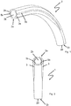
- FIG. 1 shows a curved cannula tube 2 of a tracheostomy tube 1 according to the invention according to a first embodiment without profile elements.
- the cannula tube 2 is made of plastic and has a proximal end 2a with a proximal opening 2b and a distal end 2c with a distal opening 2d. Over part of its outside, the cannula tube 2 has two recessed areas with reduced wall thickness, each of which defines a recess 2e extending in the axial direction.
- the recesses 2e are arranged diametrically on opposite sides of the cannula tube 2.
- the recesses 2e extend from the proximal end 2a of the cannula tube 2 in the axial direction of the cannula tube 2.
- the recesses 2e end at a distance in front of the distal end 2b of the cannula tube 2.
- a suitably shaped profile element 3 can be inserted into each of the recesses 2e, as shown in FIG Figure 2 and more in detail in Figure 3a-c is shown in sections.
- Each profile element 3 has two grooves 3 a, which extend in the axial direction of the tracheostomy tube 1.
- the grooves 3a are arranged between the profile element 3 and the cannula tube 2, more precisely the base of the recess (s).
- the grooves 3 a face the cannula tube 2 and are covered by a surface section of the cannula tube 2 facing the respective profile element 3.
- the grooves 3a and the respective facing surfaces of the cannula tube 2 delimit the inner cross-section of the separate lines 4, which are consequently formed between facing surfaces of the profile element 3 and the recess 2e.
- Two of the total of four lines 4 shown have a larger internal cross-section than the other two lines 4.
- the lines 4 with a larger hydraulic cross-section are preferably used for the passage of liquid and the lines 4 with a smaller cross section are preferably used for the passage of gas.
- One of the lines 4 can be connected to a cuff so that it can be filled by means of a fluid supplied through the lines 4.
- Each of the profile elements 3 can be locked in one of the recesses 2e with locking means 5.
- the profile elements 3 have a latching receptacle 5a into which a latching lug 5b arranged on the cannula tube 2 in the recess 2e engages.
- the profile elements 3 are glued to the cannula tube 2. As a result of the gluing, the profile elements 3 are not only permanently connected to the cannula tube 2, but the lines 4 are also additionally sealed.
- the cannula tube 2 and the profile elements 3 are made of plastic, the plastic of the cannula tube 2 being softer than the plastic of the profile elements 3. Inserted into the recesses 2e of the cannula tube 2, the profile elements 3 stabilize the tracheostomy tube 1 and prevent unwanted kinking of the relatively soft cannula tube 2, which could otherwise block the lines 4 or the central lumen for the passage of breathing gas.
- the recesses 2e and the profile elements 3 are therefore arranged on opposite sides of the cannula tube 2 in a mirror image with respect to the plane defined by the arc of curvature of the central axis of the lumen.
- the profile elements 3 and the recesses 2e of the cannula tube 2 are designed such that the profile elements 3 inserted into the recesses 2e terminate with the outer surface of the cannula tube 2 and form an essentially closed outer contour.
- the profile elements 3 have a cylindrical outer surface which, together with the outer surface of the cannula tube 2c, form a circular outer contour of the tracheostomy tube 1.
- FIG 3a is the proximal end 2a of the tracheostomy tube 1 from the Figures 1 and 2 shown in a perspective detailed view.
- the inner wall of the cannula tube 2 has at least one (or preferably several diametrically opposite) sliding section 3b, which extends in the axial direction and is partially received in a slot or groove-like wall recess of the cannula tube 2 and partially into the central lumen of the cannula tube 2 extends and by 0.1 mm to 0.5 mm, measured from the inner wall of the cannula tube 2, protrudes into this.
- the sliding section is formed in one piece with the profile element and extends through a slot-shaped opening extending in the axial direction of the cannula tube 2.
- the slide sections 3b which preferably run on diametrically opposite sides, each have a slide-on bevel 3c at their ends.
- the imaginary center lines of the profile elements 3 arranged on opposite sides of the cannula tube 2 are at 90 ° to 270 °.
- the total of four sliding sections 3b of the two profile elements 3 are arranged at 45 °, 135 °, 225 ° and 315 °.
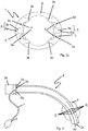
- FIG. 4 a further embodiment of a tracheostomy tube 1 according to the invention is shown, wherein in FIG Figure 5 the associated cannula tube 2 'is shown without profile elements 3.
- the cannula tube 2 ' has two regions with reduced wall thickness, recessed in cross section over part of its circumference on its outside, each defining a recess 2e extending in the axial direction.
- the profile elements 3 and the recesses 2c of the cannula tube 2 ' extend from the proximal end 2a to the distal end 2c of the cannula tube 2'.
- the cannula tube 2 ' has a conical outer cross section tapering in the direction of the distal end 2c.
- the proximal end 2a of the cannula tube 2 ' has a cannula shield 2g which is formed as one piece together with the cannula tube 2'.
- the cannula tube 2 'and the cannula shield 2g are made of a softer plastic than the profile elements 3, which in comparison are made of a harder plastic.
- the cannula shield 2g additionally has two openings 2i for the attachment of a cannula strap and two lateral openings 2h which are arranged to the side of the proximal opening 2b of the cannula tube 2.
- a profile element 3 can be passed through each of the lateral openings 2h from the proximal direction in such a way that the profile elements 3 guided through can be introduced into the recesses 2e of the cannula tube 2 adjoining the openings 2h.
- a connector 3d which is manufactured together with the profile elements 3 as one piece, is in engagement with the proximal opening 2b of the cannula tube 2.
- the recesses 2e have a locking lug 5b which extends in the axial direction of the cannula tube 2 '.
- the latching lug 5b can be brought into engagement with a latching lug receptacle 5a which is arranged on the inside of the profile elements 3.
- the profile elements 3 each have a groove 3a which extend in the axial direction of the profile element 3. If the profile elements 3 are fastened in the recesses 2e of the cannula tube 2 ', the grooves 3a together with the surface of the cannula tube 2' facing the respective profile element 3 delimit the inner cross-section of a line 4.
- One or more of the separate lines 4 are used for suctioning off Secretion, the profile elements 3 having openings for this purpose, which are connected to the lines 4.
- One or more lines 4 are connected to a cuff 6 and via a filling hose 7 to a filling valve 8. With the filling valve 8, fluid can be applied to the cuff 6 via the filling hose 7 and the line 4, or a fluid can be discharged from the cuff 6.
- the cannula tube 2 ' has a plurality of recesses 2j distributed in the circumferential direction.
- the recesses 2j increase the flexibility of the cannula tube 2 '.
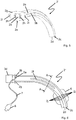
- the Figures 6 and 7th show a further embodiment of a tracheostomy tube 1 according to the present invention, wherein the Figure 6 a partially broken away side view and the Figure 7 a cross section along the in the Figure 6 show section line AA shown.
- the ones in the Figures 6 and 7th The embodiment shown differs from the embodiments of FIG Figures 1 to 5 in the design of the profile element and its connection with the cannula tube 2 ′′.
- the cannula tube 2 ′′ of the tracheal cannula 1 ′′ is made of plastic and has a proximal end 2a with a proximal opening 2b, a distal end 2c with a distal opening 2d and four separate lines 4 extending in the axial direction of the cannula tube 2 ′′ two of the four lines 4 are formed between the mutually facing surfaces of a profile element 3 and a recess 2e in the cannula tube 2 ′′.
- the two profile elements 3 are arranged diametrically on opposite sides of the cannula tube 2 ′′ and extend in the axial direction of the cannula tube 2 ′′.
- the cannula tube 2 ′′ is curved, with two recesses 2e separated by a web 2f for receiving a branch of the profile elements 3 separated in the region of the web 2f in the region of the curve. Accordingly, each of the profile elements 3 has a complementary recess 3e for receiving the Web 2f.
- the web 2f is made of a plastic that is softer than the profile elements 3. In this way, the webs increase the flexibility of the cannula tube 2 ′′ Area of curvature, while the profile elements 3 still sufficiently prevent the cannula tube 2 ′′ from narrowing by kinking.
- a plurality of recesses 2j are arranged in a peripheral section of the cannula tube 2 ′′, which is covered by a cuff 6 arranged on the cannula tube.
Landscapes
- Health & Medical Sciences (AREA)
- Pulmonology (AREA)
- Emergency Medicine (AREA)
- Engineering & Computer Science (AREA)
- Anesthesiology (AREA)
- Biomedical Technology (AREA)
- Heart & Thoracic Surgery (AREA)
- Hematology (AREA)
- Life Sciences & Earth Sciences (AREA)
- Animal Behavior & Ethology (AREA)
- General Health & Medical Sciences (AREA)
- Public Health (AREA)
- Veterinary Medicine (AREA)
- External Artificial Organs (AREA)
- Prostheses (AREA)
Claims (17)
- Canule trachéale (1), en particulier canule de trachéostomie ou tube endotrachéal, avec un tube de canule (2) en matière plastique présentant une extrémité proximale (2a) munie d'une ouverture proximale (2b), une extrémité distale (2c) munie d'une ouverture distale (2d) et au moins un conduit (4) séparé s'étendant dans la direction axiale du tube de canule (2), et un élément profilé (3) réalisé à partir d'une matière plastique qui est plus dure que la matière plastique du tube de canule (2), caractérisée en ce que le tube de canule (2) présente, sur une partie de sa circonférence et sur sa face extérieure, une région d'épaisseur de paroi réduite située en retrait en coupe transversale, de sorte qu'un évidement (2e) s'étendant dans la direction axiale est défini sur la face extérieure du tube de canule afin d'accueillir au moins partiellement l'élément profilé (3) de forme appropriée, dans laquelle le conduit (4) est formé entre les surfaces, orientées l'une vers l'autre, de l'élément profilé (3) et l'évidement de sorte que sa section transversale intérieure est limitée par une partie de surface, tournée vers le tube de canule, de l'élément profilé (3) et une partie de surface, tournée vers l'élément profilé, du tube de canule.
- Canule trachéale (1) selon la revendication 1, caractérisée en ce que la partie de surface, délimitant la section transversale intérieure du conduit (4) et tournée vers le tube de canule (2), de l'élément profilé (3) est formée par une rainure (3a) qui s'étend dans la direction longitudinale le long de l'élément profilé (3), et/ou la partie de surface, délimitant la section transversale intérieure du conduit (4) et tournée vers l'élément profilé (3), du tube de canule (2) est réalisée sous forme de rainure (2f).
- Canule trachéale (1) selon la revendication 1 ou 2, caractérisée en ce qu'au moins un autre conduit (4) s'étendant dans la direction axiale du tube de canule (2) est réalisé entre le tube de canule (2) et l'élément profilé (3).
- Canule trachéale (1) selon l'une quelconque des revendications 1 à 3, caractérisée en ce que le au moins un conduit (4) présente un diamètre hydraulique situé dans la plage comprise entre 0,3 mm et 1 mm et/ou en ce que, lorsqu'il y a plusieurs conduits (4), au moins un desdits conduits présente un diamètre hydraulique situé dans la plage comprise entre 1 mm et 4 mm.
- Canule trachéale (1) selon l'une quelconque des revendications 1 à 4, caractérisée en ce que la surface extérieure de l'élément profilé (3) forme avec la surface extérieure du tube de canule (2) un contour extérieur essentiellement fermé, de manière préférée de forme circulaire ou elliptique, dans laquelle l'élément profilé (3) est agencé dans un évidement (2e) correspondant présent au sein de la surface extérieure du tube de canule (2).
- Canule trachéale (1) selon l'une quelconque des revendications 1 à 5, caractérisée en ce que l'élément profilé (3) et le tube de canule (2) sont reliés l'un à l'autre par complémentarité de forme et/ou de force, de manière préférée par encliquetage.
- Canule trachéale (1) selon l'une quelconque des revendications 1 à 6, caractérisée en ce que la matière plastique du tube de canule (2) présente une dureté Shore A située dans une plage comprise entre 40 et 90, de manière préférée une dureté Shore A située dans une plage comprise entre 70 et 80, et la matière plastique de l'élément profilé (3) présente de manière préférée une dureté Shore située dans une plage comprise entre A90 et D70.
- Canule trachéale (1) selon l'une quelconque des revendications 1 à 7, caractérisée en ce qu'une partie de glissement (3b) réalisée en une matière plastique plus dure, s'étendant dans la direction axiale du tube de canule (2), agencée en partie dans un évidement au sein de la paroi du tube de canule et faisant saillie dans la lumière centrale du tube de canule (2) sur une distance comprise de manière préférée entre 0,1 mm et 0,5 mm à partir de la paroi intérieure du tube de canule, est prévue au niveau de la paroi intérieure du tube de canule.
- Canule trachéale (1) selon la revendication 8, caractérisée en ce que la partie de glissement (3b) est réalisée d'un seul tenant avec l'élément profilé (3) et fait saillie dans la lumière centrale du tube de canule (2) à travers une ouverture en forme de fente dudit tube de canule (2) s'étendant sur une partie de la longueur du tube de canule (2).
- Canule trachéale (1) selon la revendication 8 ou 9, caractérisée en ce que la partie de glissement (3b) faisant saillie dans la lumière centrale du tube de canule (2) présente un biseau de glissement (3c).
- Canule trachéale (1) selon l'une quelconque des revendications 1 à 10, caractérisée en ce que le tube de canule (2) et/ou l'élément profilé (3) présente un élément de contraste destiné à un procédé d'imagerie, de manière préférée au diagnostic par rayons X, à la tomographie par résonance magnétique ou à la sonographie.
- Canule trachéale (1) selon l'une quelconque des revendications 1 à 11, caractérisée en ce que l'élément profilé (3) présente un connecteur (3d) permettant le raccordement d'un dispositif de respiration artificielle, dans laquelle l'élément profilé (3) et le connecteur (3c) sont réalisés de manière préférée d'un seul tenant à partir de la même matière plastique.
- Canule trachéale (1) selon l'une quelconque des revendications 1 à 12, caractérisée en ce que le tube de canule (2) présente sur sa surface extérieure un second évidement avec un second élément profilé (3) s'étendant dans la direction axiale, dans laquelle au moins un autre conduit (4) s'étendant de manière axiale est réalisé entre l'élément profilé (3) et le tube de canule (2), dans laquelle le second élément profilé (2) et/ou l'autre conduit (4) sont réalisé(s) selon l'une quelconque des revendications précédentes.
- Canule trachéale (1) selon l'une quelconque des revendications 1 à 13, caractérisée en ce que l'évidement (2e) s'étendant dans la direction axiale présente une saillie, de manière préférée une nervure (2f) s'étendant de manière axiale, et l'élément profilé (3) inséré dans l'évidement présente un évidement (3e) réalisé de manière complémentaire par rapport à la saillie.
- Canule trachéale (1) selon l'une quelconque des revendications 1 à 14, caractérisée en ce que la paroi intérieure et/ou extérieure du tube de canule (2) se rétrécit de manière conique dans la direction axiale entre l'extrémité proximale et l'extrémité distale.
- Canule trachéale (1) selon l'une quelconque des revendications 1 à 15, caractérisée en ce que le tube de canule (2) présente un écran de canule (2g) surmoulé, dans laquelle l'écran de canule (2g) et le tube de canule (2) sont de manière préférée réalisés d'un seul tenant à partir de la même matière plastique.
- Procédé de fabrication de la canule trachéale (1) selon l'une quelconque des revendications 1 à 16, comprenant les étapes consistant à- fournir un tube de canule (2) avec une paroi extérieure en retrait le long d'au moins une partie circonférentielle et une épaisseur de paroi réduite de manière correspondante, de sorte qu'un évidement s'étendant dans la direction axiale est défini sur la face extérieure du tube de canule- fournir le au moins un élément profilé (3),- agencer le au moins un élément profilé (3) dans l'évidement sur la face extérieure du tube de canule (2) par complémentarité de force et/ou de forme, et- relier de manière étanche le au moins un élément profilé (3) à la surface extérieure du tube de canule (2) sur la longueur axiale de l'élément profilé.
Applications Claiming Priority (2)
| Application Number | Priority Date | Filing Date | Title |
|---|---|---|---|
| DE102017106750.7A DE102017106750A1 (de) | 2017-03-29 | 2017-03-29 | Trachealkanüle mit einer integrierten Leitung |
| PCT/EP2018/057816 WO2018178098A1 (fr) | 2017-03-29 | 2018-03-27 | Canule trachéale pourvue d'une conduite intégrée |
Publications (2)
| Publication Number | Publication Date |
|---|---|
| EP3600507A1 EP3600507A1 (fr) | 2020-02-05 |
| EP3600507B1 true EP3600507B1 (fr) | 2021-07-28 |
Family
ID=61911551
Family Applications (1)
| Application Number | Title | Priority Date | Filing Date |
|---|---|---|---|
| EP18716158.3A Active EP3600507B1 (fr) | 2017-03-29 | 2018-03-27 | Canule trachéale pourvue d'une conduite intégrée |
Country Status (3)
| Country | Link |
|---|---|
| EP (1) | EP3600507B1 (fr) |
| DE (1) | DE102017106750A1 (fr) |
| WO (1) | WO2018178098A1 (fr) |
Families Citing this family (3)
| Publication number | Priority date | Publication date | Assignee | Title |
|---|---|---|---|---|
| DE102020115938B4 (de) | 2020-06-17 | 2025-11-06 | Andreas Fahl Medizintechnik-Vertrieb Gmbh | Trachealkanüle |
| US20230248931A1 (en) * | 2020-12-11 | 2023-08-10 | Blake J. Hyde | Irrigating cannula system |
| US11786683B2 (en) * | 2020-12-11 | 2023-10-17 | Blake J. Hyde | Irrigating intraluminal suction inner cannula system |
Family Cites Families (8)
| Publication number | Priority date | Publication date | Assignee | Title |
|---|---|---|---|---|
| DE3522782A1 (de) * | 1985-06-26 | 1987-01-15 | Peter Brehm Chir Mechanik Werk | Doppellumige follikelpunktionskanuele |
| US5360414A (en) * | 1992-10-08 | 1994-11-01 | Yarger Richard J | Tube for draining body cavities, viscera and wounds |
| US5647358A (en) * | 1996-03-20 | 1997-07-15 | Vilasi; Joseph | Expandable inter vivos tube |
| DE19734821A1 (de) | 1997-08-12 | 1999-02-18 | Tracoe Medizine Ges Fuer | Endotracheal- oder Tracheotomietubus |
| KR100530293B1 (ko) * | 1999-06-08 | 2005-11-22 | 에드워즈 라이프사이언시스 코포레이션 | 다중 루멘 접근 장치 |
| US20040255951A1 (en) * | 2003-02-07 | 2004-12-23 | Christopher Grey | Endotrachael tube with suction catheter and system |
| US7921847B2 (en) * | 2005-07-25 | 2011-04-12 | Intubix, Llc | Device and method for placing within a patient an enteral tube after endotracheal intubation |
| DE102008015050A1 (de) * | 2008-03-19 | 2009-09-24 | Tracoe Medical Gmbh | Tracheostomiekanüle aus mindestens zwei verschiedenen Kunststoffen |
-
2017
- 2017-03-29 DE DE102017106750.7A patent/DE102017106750A1/de active Pending
-
2018
- 2018-03-27 WO PCT/EP2018/057816 patent/WO2018178098A1/fr not_active Ceased
- 2018-03-27 EP EP18716158.3A patent/EP3600507B1/fr active Active
Also Published As
| Publication number | Publication date |
|---|---|
| DE102017106750A1 (de) | 2018-10-04 |
| EP3600507A1 (fr) | 2020-02-05 |
| WO2018178098A1 (fr) | 2018-10-04 |
Similar Documents
| Publication | Publication Date | Title |
|---|---|---|
| EP0631508B1 (fr) | Catheter d'aspiration | |
| DE69108219T2 (de) | Mehrlumiger Katheter. | |
| EP2349427B1 (fr) | Masque laryngé pourvu d'un passage oesophagien | |
| DE69109268T2 (de) | Zusammengesetzter trachealtubus. | |
| EP0338380B1 (fr) | Cathéter d'aspiration pour la trachée et le système bronchial | |
| DE69321257T2 (de) | Gebogener koaxial-katheter | |
| DE3789716T2 (de) | Mechanisch verstärkter Tubus für Heilzwecke. | |
| EP3535002B1 (fr) | Canule de trachéotomie | |
| DE2547796A1 (de) | Saugkatheter | |
| EP3600507B1 (fr) | Canule trachéale pourvue d'une conduite intégrée | |
| DE3521056A1 (de) | Selbstabdichtendes rueckschlag- bzw. absperrventil | |
| WO2009115403A1 (fr) | Canule de trachéotomie composée d’au moins deux matières plastiques différentes | |
| DE2353641A1 (de) | Katheter | |
| DE102009054573A1 (de) | Tracheostomiekanüle mit Fenster | |
| DE102014109001A1 (de) | Trachealbeatmungsvorrichtung | |
| DE112015002454T5 (de) | Katheter, Katheterherstellungsform, und Katheterherstellungsverfahren | |
| DE102013011177A1 (de) | Universell positionierbares Wasserfallensystem für Atemschlauchsysteme | |
| EP2947364B1 (fr) | Dispositif de raccord pour flexibles et appareil de massage doté d'un tel dispositif de raccord | |
| DE1951236B1 (de) | Trachealkanuele | |
| EP1663382A1 (fr) | Raccord de tuyaux enfichable | |
| WO2019211216A1 (fr) | Dispositif de respiration trachéale doté d'une étanchéité | |
| DE3731590C1 (en) | Medical probe | |
| EP3727538B1 (fr) | Canule de trachéotomie comportant une ouverture de phonation | |
| DE69220205T2 (de) | Koaxial-Katheter | |
| DE3623367A1 (de) | Kupplungseinrichtung fuer narkose- und beatmungsgeraete |
Legal Events
| Date | Code | Title | Description |
|---|---|---|---|
| STAA | Information on the status of an ep patent application or granted ep patent |
Free format text: STATUS: UNKNOWN |
|
| STAA | Information on the status of an ep patent application or granted ep patent |
Free format text: STATUS: THE INTERNATIONAL PUBLICATION HAS BEEN MADE |
|
| PUAI | Public reference made under article 153(3) epc to a published international application that has entered the european phase |
Free format text: ORIGINAL CODE: 0009012 |
|
| STAA | Information on the status of an ep patent application or granted ep patent |
Free format text: STATUS: REQUEST FOR EXAMINATION WAS MADE |
|
| 17P | Request for examination filed |
Effective date: 20191014 |
|
| AK | Designated contracting states |
Kind code of ref document: A1 Designated state(s): AL AT BE BG CH CY CZ DE DK EE ES FI FR GB GR HR HU IE IS IT LI LT LU LV MC MK MT NL NO PL PT RO RS SE SI SK SM TR |
|
| AX | Request for extension of the european patent |
Extension state: BA ME |
|
| DAV | Request for validation of the european patent (deleted) | ||
| DAX | Request for extension of the european patent (deleted) | ||
| REG | Reference to a national code |
Ref country code: DE Ref legal event code: R079 Ref document number: 502018006315 Country of ref document: DE Free format text: PREVIOUS MAIN CLASS: A61M0016040000 Ipc: B29D0023000000 |
|
| GRAP | Despatch of communication of intention to grant a patent |
Free format text: ORIGINAL CODE: EPIDOSNIGR1 |
|
| STAA | Information on the status of an ep patent application or granted ep patent |
Free format text: STATUS: GRANT OF PATENT IS INTENDED |
|
| RIC1 | Information provided on ipc code assigned before grant |
Ipc: B29D 23/00 20060101AFI20210406BHEP Ipc: A61M 16/04 20060101ALI20210406BHEP |
|
| INTG | Intention to grant announced |
Effective date: 20210507 |
|
| GRAS | Grant fee paid |
Free format text: ORIGINAL CODE: EPIDOSNIGR3 |
|
| GRAA | (expected) grant |
Free format text: ORIGINAL CODE: 0009210 |
|
| STAA | Information on the status of an ep patent application or granted ep patent |
Free format text: STATUS: THE PATENT HAS BEEN GRANTED |
|
| AK | Designated contracting states |
Kind code of ref document: B1 Designated state(s): AL AT BE BG CH CY CZ DE DK EE ES FI FR GB GR HR HU IE IS IT LI LT LU LV MC MK MT NL NO PL PT RO RS SE SI SK SM TR |
|
| REG | Reference to a national code |
Ref country code: GB Ref legal event code: FG4D Free format text: NOT ENGLISH |
|
| REG | Reference to a national code |
Ref country code: CH Ref legal event code: EP |
|
| REG | Reference to a national code |
Ref country code: AT Ref legal event code: REF Ref document number: 1414350 Country of ref document: AT Kind code of ref document: T Effective date: 20210815 |
|
| REG | Reference to a national code |
Ref country code: IE Ref legal event code: FG4D Free format text: LANGUAGE OF EP DOCUMENT: GERMAN |
|
| REG | Reference to a national code |
Ref country code: DE Ref legal event code: R096 Ref document number: 502018006315 Country of ref document: DE |
|
| REG | Reference to a national code |
Ref country code: LT Ref legal event code: MG9D |
|
| REG | Reference to a national code |
Ref country code: NL Ref legal event code: MP Effective date: 20210728 |
|
| PG25 | Lapsed in a contracting state [announced via postgrant information from national office to epo] |
Ref country code: LT Free format text: LAPSE BECAUSE OF FAILURE TO SUBMIT A TRANSLATION OF THE DESCRIPTION OR TO PAY THE FEE WITHIN THE PRESCRIBED TIME-LIMIT Effective date: 20210728 Ref country code: BG Free format text: LAPSE BECAUSE OF FAILURE TO SUBMIT A TRANSLATION OF THE DESCRIPTION OR TO PAY THE FEE WITHIN THE PRESCRIBED TIME-LIMIT Effective date: 20211028 Ref country code: NO Free format text: LAPSE BECAUSE OF FAILURE TO SUBMIT A TRANSLATION OF THE DESCRIPTION OR TO PAY THE FEE WITHIN THE PRESCRIBED TIME-LIMIT Effective date: 20211028 Ref country code: NL Free format text: LAPSE BECAUSE OF FAILURE TO SUBMIT A TRANSLATION OF THE DESCRIPTION OR TO PAY THE FEE WITHIN THE PRESCRIBED TIME-LIMIT Effective date: 20210728 Ref country code: PT Free format text: LAPSE BECAUSE OF FAILURE TO SUBMIT A TRANSLATION OF THE DESCRIPTION OR TO PAY THE FEE WITHIN THE PRESCRIBED TIME-LIMIT Effective date: 20211129 Ref country code: HR Free format text: LAPSE BECAUSE OF FAILURE TO SUBMIT A TRANSLATION OF THE DESCRIPTION OR TO PAY THE FEE WITHIN THE PRESCRIBED TIME-LIMIT Effective date: 20210728 Ref country code: FI Free format text: LAPSE BECAUSE OF FAILURE TO SUBMIT A TRANSLATION OF THE DESCRIPTION OR TO PAY THE FEE WITHIN THE PRESCRIBED TIME-LIMIT Effective date: 20210728 Ref country code: ES Free format text: LAPSE BECAUSE OF FAILURE TO SUBMIT A TRANSLATION OF THE DESCRIPTION OR TO PAY THE FEE WITHIN THE PRESCRIBED TIME-LIMIT Effective date: 20210728 Ref country code: RS Free format text: LAPSE BECAUSE OF FAILURE TO SUBMIT A TRANSLATION OF THE DESCRIPTION OR TO PAY THE FEE WITHIN THE PRESCRIBED TIME-LIMIT Effective date: 20210728 Ref country code: SE Free format text: LAPSE BECAUSE OF FAILURE TO SUBMIT A TRANSLATION OF THE DESCRIPTION OR TO PAY THE FEE WITHIN THE PRESCRIBED TIME-LIMIT Effective date: 20210728 |
|
| PG25 | Lapsed in a contracting state [announced via postgrant information from national office to epo] |
Ref country code: PL Free format text: LAPSE BECAUSE OF FAILURE TO SUBMIT A TRANSLATION OF THE DESCRIPTION OR TO PAY THE FEE WITHIN THE PRESCRIBED TIME-LIMIT Effective date: 20210728 Ref country code: LV Free format text: LAPSE BECAUSE OF FAILURE TO SUBMIT A TRANSLATION OF THE DESCRIPTION OR TO PAY THE FEE WITHIN THE PRESCRIBED TIME-LIMIT Effective date: 20210728 Ref country code: GR Free format text: LAPSE BECAUSE OF FAILURE TO SUBMIT A TRANSLATION OF THE DESCRIPTION OR TO PAY THE FEE WITHIN THE PRESCRIBED TIME-LIMIT Effective date: 20211029 |
|
| PG25 | Lapsed in a contracting state [announced via postgrant information from national office to epo] |
Ref country code: DK Free format text: LAPSE BECAUSE OF FAILURE TO SUBMIT A TRANSLATION OF THE DESCRIPTION OR TO PAY THE FEE WITHIN THE PRESCRIBED TIME-LIMIT Effective date: 20210728 |
|
| REG | Reference to a national code |
Ref country code: DE Ref legal event code: R097 Ref document number: 502018006315 Country of ref document: DE |
|
| PG25 | Lapsed in a contracting state [announced via postgrant information from national office to epo] |
Ref country code: SM Free format text: LAPSE BECAUSE OF FAILURE TO SUBMIT A TRANSLATION OF THE DESCRIPTION OR TO PAY THE FEE WITHIN THE PRESCRIBED TIME-LIMIT Effective date: 20210728 Ref country code: SK Free format text: LAPSE BECAUSE OF FAILURE TO SUBMIT A TRANSLATION OF THE DESCRIPTION OR TO PAY THE FEE WITHIN THE PRESCRIBED TIME-LIMIT Effective date: 20210728 Ref country code: RO Free format text: LAPSE BECAUSE OF FAILURE TO SUBMIT A TRANSLATION OF THE DESCRIPTION OR TO PAY THE FEE WITHIN THE PRESCRIBED TIME-LIMIT Effective date: 20210728 Ref country code: EE Free format text: LAPSE BECAUSE OF FAILURE TO SUBMIT A TRANSLATION OF THE DESCRIPTION OR TO PAY THE FEE WITHIN THE PRESCRIBED TIME-LIMIT Effective date: 20210728 Ref country code: CZ Free format text: LAPSE BECAUSE OF FAILURE TO SUBMIT A TRANSLATION OF THE DESCRIPTION OR TO PAY THE FEE WITHIN THE PRESCRIBED TIME-LIMIT Effective date: 20210728 Ref country code: AL Free format text: LAPSE BECAUSE OF FAILURE TO SUBMIT A TRANSLATION OF THE DESCRIPTION OR TO PAY THE FEE WITHIN THE PRESCRIBED TIME-LIMIT Effective date: 20210728 |
|
| PLBE | No opposition filed within time limit |
Free format text: ORIGINAL CODE: 0009261 |
|
| STAA | Information on the status of an ep patent application or granted ep patent |
Free format text: STATUS: NO OPPOSITION FILED WITHIN TIME LIMIT |
|
| 26N | No opposition filed |
Effective date: 20220429 |
|
| PG25 | Lapsed in a contracting state [announced via postgrant information from national office to epo] |
Ref country code: IT Free format text: LAPSE BECAUSE OF FAILURE TO SUBMIT A TRANSLATION OF THE DESCRIPTION OR TO PAY THE FEE WITHIN THE PRESCRIBED TIME-LIMIT Effective date: 20210728 |
|
| PG25 | Lapsed in a contracting state [announced via postgrant information from national office to epo] |
Ref country code: MC Free format text: LAPSE BECAUSE OF FAILURE TO SUBMIT A TRANSLATION OF THE DESCRIPTION OR TO PAY THE FEE WITHIN THE PRESCRIBED TIME-LIMIT Effective date: 20210728 |
|
| REG | Reference to a national code |
Ref country code: CH Ref legal event code: PL |
|
| REG | Reference to a national code |
Ref country code: BE Ref legal event code: MM Effective date: 20220331 |
|
| PG25 | Lapsed in a contracting state [announced via postgrant information from national office to epo] |
Ref country code: LU Free format text: LAPSE BECAUSE OF NON-PAYMENT OF DUE FEES Effective date: 20220327 Ref country code: LI Free format text: LAPSE BECAUSE OF NON-PAYMENT OF DUE FEES Effective date: 20220331 Ref country code: FR Free format text: LAPSE BECAUSE OF NON-PAYMENT OF DUE FEES Effective date: 20220331 Ref country code: CH Free format text: LAPSE BECAUSE OF NON-PAYMENT OF DUE FEES Effective date: 20220331 |
|
| PG25 | Lapsed in a contracting state [announced via postgrant information from national office to epo] |
Ref country code: BE Free format text: LAPSE BECAUSE OF NON-PAYMENT OF DUE FEES Effective date: 20220331 |
|
| REG | Reference to a national code |
Ref country code: DE Ref legal event code: R081 Ref document number: 502018006315 Country of ref document: DE Owner name: COLOPLAST A/S, DK Free format text: FORMER OWNER: TRACOE MEDICAL GMBH, 55268 NIEDER-OLM, DE |
|
| REG | Reference to a national code |
Ref country code: GB Ref legal event code: 732E Free format text: REGISTERED BETWEEN 20231214 AND 20231220 |
|
| PG25 | Lapsed in a contracting state [announced via postgrant information from national office to epo] |
Ref country code: MK Free format text: LAPSE BECAUSE OF FAILURE TO SUBMIT A TRANSLATION OF THE DESCRIPTION OR TO PAY THE FEE WITHIN THE PRESCRIBED TIME-LIMIT Effective date: 20210728 Ref country code: CY Free format text: LAPSE BECAUSE OF FAILURE TO SUBMIT A TRANSLATION OF THE DESCRIPTION OR TO PAY THE FEE WITHIN THE PRESCRIBED TIME-LIMIT Effective date: 20210728 |
|
| REG | Reference to a national code |
Ref country code: AT Ref legal event code: MM01 Ref document number: 1414350 Country of ref document: AT Kind code of ref document: T Effective date: 20230327 |
|
| PG25 | Lapsed in a contracting state [announced via postgrant information from national office to epo] |
Ref country code: HU Free format text: LAPSE BECAUSE OF FAILURE TO SUBMIT A TRANSLATION OF THE DESCRIPTION OR TO PAY THE FEE WITHIN THE PRESCRIBED TIME-LIMIT; INVALID AB INITIO Effective date: 20180327 |
|
| PG25 | Lapsed in a contracting state [announced via postgrant information from national office to epo] |
Ref country code: TR Free format text: LAPSE BECAUSE OF FAILURE TO SUBMIT A TRANSLATION OF THE DESCRIPTION OR TO PAY THE FEE WITHIN THE PRESCRIBED TIME-LIMIT Effective date: 20210728 |
|
| PG25 | Lapsed in a contracting state [announced via postgrant information from national office to epo] |
Ref country code: AT Free format text: LAPSE BECAUSE OF NON-PAYMENT OF DUE FEES Effective date: 20230327 |
|
| PG25 | Lapsed in a contracting state [announced via postgrant information from national office to epo] |
Ref country code: AT Free format text: LAPSE BECAUSE OF NON-PAYMENT OF DUE FEES Effective date: 20230327 |
|
| PG25 | Lapsed in a contracting state [announced via postgrant information from national office to epo] |
Ref country code: MT Free format text: LAPSE BECAUSE OF FAILURE TO SUBMIT A TRANSLATION OF THE DESCRIPTION OR TO PAY THE FEE WITHIN THE PRESCRIBED TIME-LIMIT Effective date: 20210728 |
|
| PGFP | Annual fee paid to national office [announced via postgrant information from national office to epo] |
Ref country code: GB Payment date: 20260327 Year of fee payment: 9 |
|
| PGFP | Annual fee paid to national office [announced via postgrant information from national office to epo] |
Ref country code: DE Payment date: 20260327 Year of fee payment: 9 Ref country code: IE Payment date: 20260327 Year of fee payment: 9 |
|
| PGFP | Annual fee paid to national office [announced via postgrant information from national office to epo] |
Ref country code: AT Payment date: 20260410 Year of fee payment: 5 |