EP3600932B1 - Kraftfahrzeuganrodnung mit magnetischer wasserkastenabdeckung - Google Patents
Kraftfahrzeuganrodnung mit magnetischer wasserkastenabdeckung Download PDFInfo
- Publication number
- EP3600932B1 EP3600932B1 EP18713186.7A EP18713186A EP3600932B1 EP 3600932 B1 EP3600932 B1 EP 3600932B1 EP 18713186 A EP18713186 A EP 18713186A EP 3600932 B1 EP3600932 B1 EP 3600932B1
- Authority
- EP
- European Patent Office
- Prior art keywords
- magnetic element
- motor vehicle
- profile strip
- water tank
- tank cover
- Prior art date
- Legal status (The legal status is an assumption and is not a legal conclusion. Google has not performed a legal analysis and makes no representation as to the accuracy of the status listed.)
- Active
Links
Images



Classifications
-
- B—PERFORMING OPERATIONS; TRANSPORTING
- B60—VEHICLES IN GENERAL
- B60J—WINDOWS, WINDSCREENS, NON-FIXED ROOFS, DOORS, OR SIMILAR DEVICES FOR VEHICLES; REMOVABLE EXTERNAL PROTECTIVE COVERINGS SPECIALLY ADAPTED FOR VEHICLES
- B60J10/00—Sealing arrangements
- B60J10/70—Sealing arrangements specially adapted for windows or windscreens
Definitions
- the invention relates to a motor vehicle arrangement, comprising a windshield, a profile strip attached to the windshield and a water tank cover adjoining the profile strip, a connection device being provided which comprises a first connection section assigned to the profile strip and a second connection section assigned to the water tank cover.
- Motor vehicle arrangement of the type mentioned above are, for example, from DE 200 08 555 U1 and the DE 20 2008 006 986 U1 known.
- the profile strips of this Motor vehicle assemblies are used to connect a lower edge region of a windshield of a motor vehicle to an adjacent water tank cover.
- a water tank cover is used to cover a water tank that picks up water draining from the vehicle window and drains it into the engine compartment and under the vehicle in a controlled manner.
- the water tank can be part of the vehicle body or, for example, be provided separately as a plastic component.
- a profile strip with a connecting section in the form of a U-shaped or groove-shaped receiving area is provided.
- the water tank cover has a connecting section in the form of a fastening web. To connect the water tank cover to the profile strip, the fastening web of the water tank cover is inserted into the receiving area of the profile strip and locked there.
- the assembly described above is usually carried out as part of the final assembly of a motor vehicle at motor vehicle manufacturers. The following explains which manufacturing and process steps are carried out by suppliers before this final assembly.
- the profile strip and the windshield are usually manufactured by one or more suppliers. Then the profile strip with the Edge area of the windshield connected, usually glued. This creates an assembly which comprises the windshield and the profile strip connected to the windshield. This assembly is then delivered to the motor vehicle manufacturer by one of the suppliers. There the windshield is connected to a windshield mount of a motor vehicle body; In addition, the plenum chamber cover is joined to the profile strip and latched (see above).
- the connecting section of the profile strip i.e. the section of material that delimits the U-shaped or groove-shaped receiving area
- the connecting section of the profile strip protrudes from the profile strip and the windshield and is therefore exposed to mechanical influences.
- the named assembly can be transported in a space-saving and "upright” position, that is to say that the windshield can be transported upright.
- the windshield is protected against damage to the lower edge area during transport. Such protection is ensured by the fact that the windshield is supported on the connecting section of the profile strip during its transport. However, this means that the weight of the windshield rests on the connecting section of the profile strip during transport of the assembly. This load causes an undesired deformation (compression) of the connecting section of the profile strip delimiting the receiving area.
- the transport protection strip is removed from the receiving area of the profile strip so that the connecting section can be connected to the adjacent motor vehicle component, in particular to the water tank cover.
- the transport protection strip is then disposed of.
- the beats EP 2 253 556 A1 propose to provide an additional handling section in the form of a grip tab on the transport protection strip, so that the transport protection strip can be pulled out of the receiving area of the profile strip by manually pulling the grip strip.
- a similar one Handling section in the form of a pull-out ring is from the WO 2014/041279 A1 known.
- the additional handling sections mentioned above simplify the removal of the protective transport strip from the receiving area of the profile strip.
- the transport protection strip and the handling sections must first be manufactured as individual parts and then mounted on the profile strip by the supplier. After the assembly has been transported to the motor vehicle manufacturer, the motor vehicle manufacturer must then dismantle the transport protection strip and the handling sections again. Finally, the protective transport strip and the handling sections must be collected and disposed of.
- a motor vehicle assembly with the features of the preamble of claim 1 is from DE 10 2011 087 739 A1 known. Proceeding from this, the present invention is based on the object of specifying a motor vehicle arrangement that is easier to manufacture.
- the motor vehicle arrangement according to the invention makes it possible to create a simply constructed connecting device that is effective between the water cover and the profile strip.
- the connecting section of the profile strip can be designed to be more robust than in a motor vehicle arrangement in which a fastening web of a water tank cover is inserted into a U-shaped or groove-shaped receiving area of a profile strip so as to latch.
- This makes it possible to dispense with a piping for transport protection of a U-shaped or groove-shaped receiving area of a profile strip, which in turn means that it does not have to be laboriously manufactured, assembled, then removed and finally disposed of.
- the magnetic forces acting between the magnetic elements of the water tank cover and the profile strip are sufficiently high to prevent the water tank cover from being inadvertently removed from the profile strip. At the same time, however, it is possible to remove the water tank cover from the profile strip if necessary to be able to lift off and remove and then to be able to reassemble.
- the connecting device according to the invention enables multiple and wear-free assembly and disassembly of the water tank cover.
- the assembly of the motor vehicle arrangement according to the invention is very simple. In particular, it is not necessary to maintain a precise angular and joint position of the water tank cover relative to the profile strip during the assembly of the water tank cover.
- Magneticically interacting with one another is to be understood in the sense of the invention to the effect that the magnetic elements are designed in such a way that the connecting sections of the profile strip and the water tank cover are releasably connected to one another.
- the first and / or the second magnetic element can, for example, be permanent magnet or magnetized or magnetizable. According to the invention, at least one of the magnetic elements builds up a magnetic field.
- the invention includes all possibilities with which magnetic forces can be generated between the first and the second magnetic element.
- one of the magnetic elements can be a magnet, while the respective other magnetic element is at least magnetizable, but optionally also magnetic itself.
- the first and / or the second magnetic element can be made of a material with a magnetic susceptibility ⁇ > 0 exist or comprise such a material.
- the magnetic susceptibility indicates the magnetizability of matter in an external magnetic field.
- the first and / or the second magnetic element can be paramagnetic, but it is preferably ferromagnetic, ferrimagnetic or superparamagnetic. At least the first or the second magnetic element must be magnetized and thus have permanent magnetic properties. It is also possible for both the first and the second magnetic element to have permanent magnetic properties.
- Ferromagnetic materials contain elementary magnets that can be aligned parallel to one another. This means that pieces of these materials are attracted to the magnetic pole of an external magnetic field or - if they are magnetized - even have a static magnetic field themselves. Examples of ferromagnetic materials are ⁇ -iron, cobalt, nickel.
- Ferrimagnetic substances have a crystal structure in which the magnetic moments of the atoms are alternately aligned antiparallel within certain areas (so-called Weiss areas) and are different in terms of amount. Ferrites belong to the material groups with ferrimagnetic properties.
- Paramagnetic substances only have a magnetization other than zero as long as they are in an external magnetic field.
- the randomly arranged magnetic moments of an atom or a molecule are partially aligned in an external magnetic field in such a way that the magnetic field inside the paramagnetic substance is strengthened, but only as long as the external magnetic field exists.
- Paramagnetic materials are drawn into a magnetic field. Examples of paramagnetic substances are aluminum, sodium, ⁇ -manganese, oxygen.
- Superparamagnetism describes the magnetic property of very small particles of a ferromagnetic or ferrimagnetic material not to hold permanent magnetization even at temperatures below the Curie temperature T c if a previously applied magnetic field has been switched off.
- the first or the second magnetic element is preferably a permanent magnet.
- the magnetization takes place advantageously after the production of the component by the action of an external magnetic field in a manner known per se.
- the magnetization of the first magnetic element can preferably take place in a continuous process in that the profile is passed through between the poles of an external magnet.
- This external magnet can be a permanent magnet or preferably an electromagnet.
- the first magnetic element is provided as a first additional element separately from the profile strip and in particular is positively connected to the profile strip and / or that the second magnetic element is provided as a second additional element separately from the water tank cover and in particular is positively connected to the water tank cover.
- Such an additional element can be formed, for example, by a magnetizable wire.
- a magnetizable wire can in particular be circular in cross section.
- the wire can also have cross-sectional shapes that differ from this. The magnetization of such an additional element can take place before or after the installation of the additional element on or in the profile strip or the water tank cover.
- a particularly simple way of integrating an additional element into the profile strip or the water tank cover is that the additional element is molded in during or during the manufacture of the profile strip or the water tank cover.
- the additional element can be introduced in the course of the extrusion of the profile strip and at least partially shaped by the extruded material.
- the water tank cover can be manufactured, for example, by injection molding, the additional element being arranged within the injection mold and then being formed by injected plastic material.
- an additional element to the profile strip or the water tank cover, for example by providing a recess in the profile strip or the water tank cover into which the additional element can be inserted and, in particular, can be locked there.
- the profile strip and / or the water tank cover has or have a main body made of a plastic material and a material section which is or are provided with a magnetic or magnetizable filler material or formed by such a material.
- a magnetic or magnetizable filler material or formed by such a material.
- Such components can be produced, for example, by means of a multicomponent extrusion or injection molding process.
- the filler material can be formed, for example, by ferromagnetic particles which are introduced into a material section of the profile strip or the water tank cover.
- the first magnetic element is strand-shaped and extends parallel to the longitudinal axis of the profile strip and / or that the second magnetic element is strand-shaped and extends parallel to the longitudinal axis of the water tank cover.
- a strand is preferably designed in the shape of a prism, for example cylindrical. Such a strand shape makes it possible to provide a compact magnetic element.
- the first magnetic element has a concavely curved, the second magnetic element facing boundary surface or that the second magnetic element has a concavely curved, the having the first magnetic element facing boundary surface.
- boundary surfaces can be used, for example, as interlocking connecting surfaces;
- a concavely curved boundary surface is also particularly advantageous if the other magnetic element is designed in the form of a strand. This enables the magnetic elements to work together magnetically in several directions that are angularly offset from one another.
- the first magnetic element is in one piece as seen along the longitudinal axis of the profile strip or has a plurality of magnetic element segments and / or that the second magnetic element is in one piece as seen along the longitudinal axis of the water tank cover or has a plurality of magnetic element segments.
- One-piece magnetic elements simplify the production of the profile strip or the water tank cover.
- a plurality of magnetic element segments enables weight savings.
- other functions described below can be implemented with magnetic element segments.
- the water tank cover viewed along the longitudinal axes of the profile strip and the water tank cover, there are at least two pairs of magnet element segments that are spaced apart from one another provided, each pair having magnetically interacting magnetic element segments, of which a first magnetic element segment is assigned to the profile strip and a second magnetic element segment is assigned to the water tank cover. At least four magnetic element segments are provided, which interact with one another as two pairs of magnetic element segments, so that a connection between the water tank cover and the profile strip takes place in the area of the at least two pairs. In this way, the water tank cover is attached to the profile strip at at least two points along its longitudinal axis.
- At least one first pair of magnet element segments is provided, the magnet element segments of which have first directions of magnetization in the same direction, and that at least one second pair of magnet element segments is provided, the segments of which have magnetization in the same direction, and that the first directions of magnetization are opposite to the second directions of magnetization.
- the directions of magnetization of a pair of magnet element segments are therefore in the same direction, so that in principle each pair of magnet element segments generates forces which connect the water tank cover and the profile strip to one another. Because the directions of magnetization of a first pair are opposite to the directions of magnetization of a run second pair, it is possible, however, to create an arrangement which prevents incorrect positioning of the water tank cover relative to the profile strip.
- a magnetic element segment (which has a first direction of magnetization) of a first pair faces a magnetic element segment (which has an opposite, second direction of magnetization) of a second pair.
- a repulsion force can be generated in the area of these magnetic element segments (incorrectly positioned relative to one another), which prevents the incorrectly positioned water tank cover from being joined to the profile strip.
- the connecting sections can be or are connected to one another in a form-fitting manner. In this way, a multiple connection can be created between the water tank cover of the profile strip, which comprises a form-fitting connection of the connecting sections and, in addition, a magnetic connection between the connecting sections.
- first magnetic element and the second magnetic element can be connectable or connected to one another in a form-fitting manner. In this way, too, a multiple connection can be created that includes a form fit and magnetic holding forces.
- the above-mentioned form fit can be effective along a longitudinal axis and / or a transverse axis of the motor vehicle arrangement, the longitudinal axis and the transverse axis relating to the state of the windshield installed on a motor vehicle.
- Such a form fit enables the water tank cover to be fixed within at least one direction of a plane of extent of the windshield.
- the form fit it is also possible for the form fit to be effective along a vertical axis of the motor vehicle arrangement, the vertical axis relating to the state of the windshield installed on a motor vehicle.
- This form fit counteracts the lifting of the water tank cover from the profile strip, that is to say the movement or removal of the water tank cover in a direction essentially parallel to a normal to the plane of extent of the windshield.
- a motor vehicle arrangement is designated as a whole by the reference numeral 10 in the drawing. It comprises a windshield 12 of a motor vehicle, which extends between an upper edge 14 and a lower edge 16 and between lateral edges 18, 20.
- a profile strip 22 is attached to the lower edge 16 of the windshield 12.
- a water tank cover 24 adjoins the profile strip 22.
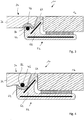
- FIGS Figure 1 Axes drawn in, with a first axis 26 forming a transverse axis of the motor vehicle arrangement 10 and the motor vehicle, an axis 28 perpendicular to this a longitudinal axis of the motor vehicle arrangement 10 and an axis 30 perpendicular to the axes 26 and 28 a vertical axis of the motor vehicle arrangement 10.
- the axes 26 and 28 span a plane which essentially corresponds to the plane of extent of the windshield; the vertical axis 30 runs perpendicular to this plane of extension.
- the profile strip 22 and at least one edge 32 of the water tank cover 24 facing the windshield 12 run parallel to the lower edge 16 of the windshield 12. This course is curved. Accordingly, the in Figure 1 indicated longitudinal axes 34 and 36 of the profile strip 22 and the water tank cover 24 have a curved course.
- connection device 38 is provided, with a first connection section 40 assigned to the profile strip 22 and with a second connection section 42 assigned to the water tank cover.
- the first connecting section 40 is in the form of a strand and extends in one piece along the entire length of the profile strip 22.
- the first connecting section 40 is semicircular in profile (cf. Figure 2 ) and formed by a first magnetic element 44.
- the second connecting section 42 is formed by a second magnetic element 46.
- the second magnetic element 46 is shell-shaped and has a concavely curved boundary surface 48 facing the first magnetic element 44.
- the second magnetic element 46 has a plurality of magnetic element segments 46a, 46b, 46c, 46d, 46e, seen along the longitudinal axis 36 of the water tank cover 24, cf. Figure 1 .
- the magnetic element segments 46a to 46e are arranged distributed along the longitudinal axis 36, in particular arranged regularly distributed.
- the windshield 12 extends between an outer side 50 and an inner side 52.
- the water tank cover 24 extends between an outer surface 54 and an inner surface 56.
- the profile strip 22 has a web-shaped fastening section 58 which extends parallel to the underside 52 of the windshield 12 and is connected to the windshield 12 by means of an adhesive 60.
- the profile strip 22 also has a main body 62 which is solid in cross section and which carries a sealing section 64 on its upper side.
- the sealing section 64 has an outer surface 66. It is preferred that the outside 50 of the windshield 12, the outside surface 66 of the sealing portion 64, and the outside surface 54 of the plenum chamber cover 24 are flush with one another.
- the profile strip 22 is made of an elastic plastic material. In order to stiffen the profile strip 22, in particular metallic reinforcement inserts 68, 70 can be provided.
- the main body 62 has a lateral delimiting surface 72 which runs parallel to the lower edge 16 of the windshield 12.
- the lateral boundary surface 72 is used in a state in which the The water tank cover 24 is not yet connected to the profile strip 22 (cf. Figure 1 ), as a mounting surface for a "standing" transport of an assembly which comprises the windshield 12 and the profile strip 22 attached to it.
- the main body 62 also has an upper delimiting surface 74 on which the first magnetic element 44 is arranged.
- the plenum chamber cover 24 has a main body 76 made of a plastic material and extending between the outer surface 54 and the inner surface 56.
- the main body 76 has, on the underside facing away from the outer surface 54, a concavely curved receiving surface 78 for receiving the second magnetic element 46 or a respective magnetic element segment (46a to 46e).
- the magnetic elements 44 and 46 can be material sections which are connected in one piece or integrally formed with the respective main bodies 62, 76 and which are provided with a magnetic or magnetizable filler material.
- the magnet elements 44 or 46 can, however, also be provided as an additional element and can be connected to the respective boundary surfaces 74 or 78 of the main body 62 or 76, for example by a form fit or material fit (gluing).
- the illustrated embodiments have at least one magnetic element 44, 46, which is provided as a strand-like additional element, for example in the form of a magnetizable wire. This is the embodiment according to FIG Figure 3 around the first magnetic element 44 and in the embodiment according to FIG Figure 4 around the second magnetic element 46.
- the first magnetic element 44 is received in a groove-shaped receptacle 80 of the main body 62 of the profile strip 22 in a positively locking manner.
- the second magnetic element 46 is received in a positively locking manner in a U-shaped receptacle 82 of the main body 76 of the water tank cover 24.
- first magnetic element 44 and the second magnetic element 46 touch one another.
- a strand-like, first magnetic element 44 is provided, which is encased in the circumferential direction by a casing section 84 of the main body 62 of the profile strip 22. In this way, a concavely curved delimiting surface 48 of the second magnetic element 46 is spaced apart from the first magnetic element 44.
- a strand-shaped second magnetic element 46 is encased by a sheathing section 86 of the main body 76 of the water tank cover 24, so that the second magnetic element 46 is spaced from a concave boundary surface 88 of the first magnetic element 44 to the second magnetic element 46.
- the motor vehicle arrangement 10 comprises a profile strip 22 with a main body 62 which, together with a leg 90, delimits a U-shaped receiving area 92.
- This receiving area 92 serves to receive a fastening web 94, which protrudes from the underside 56 of the main body 76 of the water tank cover 24.
- the profile strip 22 according to Figure 7 also has a latching element 96 which is designed as a latching lip.
- the latching element 96 forms a first connecting section 40; the fastening web 94 of the water tank cover 24 forms a second connecting section 42.
- the latching element 96 is provided at least in a partial area with a first magnetic element 44 which extends in the longitudinal direction of the profile strip 22.
- This can be a magnetic or magnetizable wire which is introduced into the latching element 96 by way of the extrusion process, for example.
- the fastening web 94 has a latching element receptacle 98 for receiving the latching element 96 in a form-fitting manner.
- the latching element receptacle 98 is provided with a second magnetic element 46 in at least one partial area. This is, for example, L-shaped or arc-shaped in cross section.
- the second magnetic element 46 can, for example, by adding ferromagnetic Particles may be formed in the plastic material of the fastening web 94.
- the form fit also acts along the vertical axis 30, opposite to one in Figure 7 Extension direction 100 of the water tank cover 24 shown.
- the magnetic elements 44 and 46 are spaced from one another. However, it is also possible for the magnetic element 44 of the latching element 96 to contact the second magnetic element 46 of the fastening web 94. It is also possible for the second magnetic element 46 to be set into the material in relation to a contact surface with the latching element 96.
- the latching element 96 is preferably made of a soft elastic material. This material can have a higher elasticity than a plastic material of the main body 62 of the profile strip 22. It is also possible to manufacture the lip-shaped locking element 96 completely from a magnetic or magnetizable material, either by adding an additional material to a plastic material or by that the latching element 96 is made entirely of a metallic material that is magnetic or magnetizable.
Landscapes
- Engineering & Computer Science (AREA)
- Mechanical Engineering (AREA)
- Electric Propulsion And Braking For Vehicles (AREA)
- Body Structure For Vehicles (AREA)
- Water Treatment By Electricity Or Magnetism (AREA)
Description
- Die Erfindung betrifft eine Kraftfahrzeuganordnung, umfassend eine Windschutzscheibe, eine an der Windschutzscheibe befestigte Profilleiste und eine an die Profilleiste angrenzende Wasserkastenabdeckung, wobei eine Verbindungseinrichtung vorgesehen ist, die einen ersten, der Profilleiste zugeordneten Verbindungsabschnitt und einen zweiten, der Wasserkastenabdeckung zugeordneten Verbindungsabschnitt umfasst.
- Kraftfahrzeuganordnung der vorstehend genannten Art sind beispielsweise aus der
DE 200 08 555 U1 und derDE 20 2008 006 986 U1 bekannt. Die Profilleisten dieser Kraftfahrzeuganordnungen dienen dazu, einen unteren Randbereich einer Windschutzscheibe eines Kraftfahrzeugs mit einer angrenzenden Wasserkastenabdeckung zu verbinden. Eine Wasserkastenabdeckung dient zur Abdeckung eines Wasserkastens, der von der Fahrzeugscheibe abfließendes Wasser aufnimmt und kontrolliert in den Motorraum und unter das Fahrzeug ableitet. Der Wasserkasten kann Bestandteil der Fahrzeugkarosserie oder beispielsweise als Kunststoffbauteil separat bereitgestellt sein. - Bei den Kraftfahrzeuganordnungen der
DE 200 08 555 U1 und derDE 20 2008 006 986 U1 ist eine Profilleiste mit einem Verbindungsabschnitt in Form eines U- oder nutförmigen Aufnahmebereichs vorgesehen. Die Wasserkastenabdeckung weist einen Verbindungsabschnitt in Form eines Befestigungsstegs auf. Zur Verbindung der Wasserkastenabdeckung mit der Profilleiste wird der Befestigungssteg der Wasserkastenabdeckung in den Aufnahmebereich der Profilleiste eingesteckt und dort verrastet. - Die vorstehend beschriebene Montage wird üblicherweise im Rahmen der Endmontage eines Kraftfahrzeugs bei Kraftfahrzeugherstellern durchgeführt. Nachfolgend wird erläutert, welche Herstellungs- und Verfahrensschritte vor dieser Endmontage bei Zuliefern durchgeführt werden.
- Die Profilleiste und die Windschutzscheibe werden üblicherweise bei einem oder mehreren Zulieferern hergestellt. Anschließend wird die Profilleiste mit dem Randbereich der Windschutzscheibe verbunden, üblicherweise verklebt. Somit entsteht eine Baugruppe, welche die Windschutzscheibe und die mit der Windschutzscheibe verbundene Profilleiste umfasst. Diese Baugruppe wird dann von einem der Zulieferer an den Kraftfahrzeughersteller geliefert. Dort wird die Windschutzscheibe mit einer Windschutzscheibenaufnahme einer Kraftfahrzeugkarosserie verbunden; außerdem wird die Wasserkastenabdeckung mit der Profilleiste gefügt und verrastet (s.o.).
- Während des Transports der Baugruppe "Windschutzscheibe und Profilleiste" von dem Zulieferer zu dem Kraftfahrzeughersteller ragt der Verbindungsabschnitt der Profilleiste, also der Materialabschnitt, der den U- oder nutförmigen Aufnahmebereich begrenzt, von der Profilleiste und der Windschutzscheibe ab und ist somit mechanischen Einflüssen ausgesetzt. Gleichzeitig ist es aber erwünscht, dass die genannte Baugruppe platzsparend und "stehend" transportiert werden kann, dass also die Windschutzscheibe hochkant transportiert werden kann. Außerdem ist es erwünscht, dass die Windschutzscheibe während des Transports gegen eine Beschädigung des unteren Randbereichs geschützt ist. Ein solcher Schutz ist dadurch gewährleistet, dass sich die Windschutzscheibe während ihres Transports auf dem Verbindungsabschnitt der Profilleiste abstützt. Dies bedeutet aber, dass das Gewicht der Windschutzscheibe während des Transports der Baugruppe auf dem Verbindungsabschnitt der Profilleiste lastet. Diese Belastung bewirkt eine unerwünschte Verformung (Stauchung) des den Aufnahmebereich begrenzenden Verbindungsabschnitts der Profilleiste.
- Zur Vermeidung einer Verformung einer mit einer Windschutzscheibe verbundenen Profilleiste ist es aus dem Stand der Technik (beispielsweise aus der
WO 2006/002891 A2 , derEP 2 253 556 A1 und derWO 2014/041279 A1 ) bekannt, den Verbindungsabschnitt der Profilleiste dadurch zu versteifen, dass eine Transportschutzleiste (auch "Keder" genannt) verwendet wird, die mit zumindest einem Teilbereich ihres Querschnitts in dem Aufnahmebereich des Verbindungsabschnitts angeordnet wird. - Nach Anlieferung der Baugruppe "Windschutzscheibe und Profilleiste" bei dem Kraftfahrzeughersteller wird die Transportschutzleiste wieder aus dem Aufnahmebereich der Profilleiste entfernt, damit der Verbindungsabschnitt mit dem angrenzenden Kraftfahrzeugbauteil, insbesondere mit der Wasserkastenabdeckung, verbunden werden kann. Die Transportschutzleiste wird anschließend entsorgt.
- Zur Entfernung der Transportschutzleiste aus dem Aufnahmebereich des Verbindungsabschnitts der Profilleiste schlägt die
EP 2 253 556 A1 vor, an der Transportschutzleiste einen zusätzlichen Handhabungsabschnitt in Form einer Grifflasche vorzusehen, sodass die Transportschutzleiste durch manuelles Ziehen an der Grifflasche aus dem Aufnahmebereich der Profilleiste herausgezogen werden kann. Ein ähnlicher Handhabungsabschnitt in Form eines Ausziehrings ist aus derWO 2014/041279 A1 bekannt. - Die vorstehend genannten, zusätzlichen Handhabungsabschnitte vereinfachen die Entfernung der Transportschutzleiste aus dem Aufnahmebereich der Profilleiste. Die Transportschutzleiste und die Handhabungsabschnitte müssen aber zunächst als Einzelteile hergestellt werden und dann vom Zulieferer an der Profilleiste montiert werden. Nach dem Transport der Baugruppe zu dem Kraftfahrzeughersteller muss der Kraftfahrzeughersteller die Transportschutzleiste und die Handhabungsabschnitte dann wieder demontieren. Schließlich müssen die Transportschutzleiste und die Handhabungsabschnitte gesammelt und entsorgt werden.
- Bei den aus dem Stand der Technik bekannten Kraftfahrzeuganordnungen ist weiterhin nachteilig, dass zur Verbindung der Wasserkastenabdeckung mit der Profilleiste eine bestimmte Fügerichtung vorgegeben ist und eingehalten werden muss. Auch die Winkellage der Wasserkastenabdeckung relativ zu der Baugruppe "Windschutzscheibe und Profilleiste" muss innerhalb enger Grenzen eingehalten werden, damit die Montage gelingt.
- Eine Kraftfahrzeuganordnung mit den Merkmalen des Oberbegriffs des Patentanspruchs 1 ist aus der
DE 10 2011 087 739 A1 bekannt. Hiervon ausgehend liegt der vorliegenden Erfindung die Aufgabe zugrunde, eine einfacher herstellbare Kraftfahrzeuganordnung anzugeben. - Diese Aufgabe wird bei einer Kraftfahrzeuganordnung mit den Merkmalen des Oberbegriffs des Patentanspruchs 1 erfindungsgemäß durch die kennzeichnenden Merkmale des Patentanspruchs 1 gelöst.
- Die erfindungsgemäße Kraftfahrzeuganordnung ermöglicht es, eine einfach aufgebaute Verbindungseinrichtung zu schaffen, die zwischen Wasserabdeckung und Profilleiste wirksam ist. Durch die Verwendung der Magnetelemente ist es möglich, die Geometrie der Verbindungsabschnitte der Wasserkastenabdeckung und der Profilleiste zu vereinfachen. Insbesondere kann der Verbindungsabschnitt der Profilleiste robuster ausgestaltet werden als bei einer Kraftfahrzeuganordnung, bei welcher ein Befestigungssteg einer Wasserkastenabdeckung in einen U- oder nutförmigen Aufnahmebereich einer Profilleiste rastend eingesetzt wird. Dies wiederum ermöglicht es, auf einen Keder zum Transportschutz eines U- oder nutförmigen Aufnahmebereichs einer Profilleiste verzichten zu können, was wiederum bedeutet, dass dieser nicht aufwändig hergestellt, montiert, anschließend entfernt und schließlich entsorgt werden muss.
- Die zwischen den Magnetelementen der Wasserkastenabdeckung und der Profilleiste wirkenden Magnetkräfte sind ausreichend hoch, um ein unbeabsichtigtes Entfernen der Wasserkastenabdeckung von der Profilleiste zu verhindern. Gleichzeitig ist es jedoch möglich, die Wasserkastenabdeckung bei Bedarf von der Profilleiste abheben und entfernen zu können und anschließend wieder montieren zu können. Die erfindungsgemäße Verbindungseinrichtung ermöglicht eine mehrfache und verschleißfreie Montage und Demontage der Wasserkastenabdeckung.
- Die Montage der erfindungsgemäßen Kraftfahrzeuganordnung gestaltet sich als sehr einfach. Insbesondere ist es nicht erforderlich, während der Montage der Wasserkastenabdeckung eine genaue Winkel- und Fügelage der Wasserkastenabdeckung relativ zu der Profilleiste einzuhalten.
- "Magnetisch miteinander zusammenwirken" ist im Sinne der Erfindung dahingehend zu verstehen, dass die Magnetelemente so ausgebildet sind, dass die Verbindungsabschnitte der Profilleiste und der Wasserkastenabdeckung lösbar miteinander verbunden sind. Das erste und/oder das zweite Magnetelement kann z.B. dauermagnetisch oder magnetisiert oder magnetisierbar sein. Erfindungsgemäß baut zumindest eines der Magnetelemente ein Magnetfeld auf.
- Die Erfindung umfasst alle Möglichkeiten, mit denen zwischen dem ersten und dem zweiten Magnetelement magnetische Kräfte erzeugt werden können. So kann eines der Magnetelemente ein Magnet sein, während das jeweils andere Magnetelement zumindest magnetisierbar, optional aber auch selbst magnetisch ist.
- Das erste und/oder das zweite Magnetelement kann aus einem Material mit einer magnetischen Suszeptibilität χ > 0 bestehen oder ein solches Material umfassen. Die magnetische Suszeptibilität gibt die Magnetisierbarkeit von Materie in einem externen Magnetfeld an. Die magnetische Permeabilität µr (auch magnetische Leitfähigkeit) bestimmt die Durchlässigkeit von Materie für magnetische Felder. Da die magnetische Suszeptibilität χ und die relative magnetische Permeabilität µr eines Stoffes durch die Beziehung X = µr - 1 miteinander verknüpft sind, haben geeignete Materialien zugleich eine relative Permeabilität (oder Permeabilitätszahl) µr > 1. Die Suszeptibilität lässt sich experimentell bspw. mit einer Gouyschen Waage oder mit einer Faraday-Waage bestimmen.
- Das erste und/oder das zweite Magnetelement kann dabei paramagnetisch sein, es ist jedoch bevorzugt ferromagnetisch, ferrimagnetisch oder superparamagnetisch. Zumindest das erste oder das zweite Magnetelement muss magnetisiert sein und somit dauermagnetische Eigenschaften aufweisen. Es ist auch möglich, dass sowohl das erste und das zweite Magnetelement dauermagnetische Eigenschaften aufweisen.
- Ferromagnetische Materialien enthalten Elementarmagnete, die parallel zueinander ausgerichtet sein können. Das bedeutet, dass Stücke dieser Materialien vom Magnetpol eines äußeren Magnetfelds angezogen werden oder - wenn sie magnetisiert sind - sogar selbst ein statisches Magnetfeld aufweisen. Beispiele für ferromagnetische Materialien sind α-Eisen, Kobalt, Nickel.
- Ferrimagnetische Stoffe besitzen eine Kristallstruktur, bei der innerhalb bestimmter Bereiche (sogenannte Weiss-Bezirke) die magnetischen Momente der Atome jeweils abwechselnd antiparallel ausgerichtet und dabei betragsmäßig unterschiedlich sind. Zu den Material-Gruppen mit ferrimagnetischen Eigenschaften gehören die Ferrite.
- Paramagnetische Stoffe weisen nur so lange eine von Null verschiedene Magnetisierung auf, wie sie sich in einem externen Magnetfeld befinden. Die regellos angeordneten magnetischen Momente eines Atoms oder eines Moleküls richten sich teilweise in einem externen Magnetfeld so aus, dass sich das Magnetfeld im Inneren des paramagnetischen Stoffes verstärkt, jedoch nur solange das äußere Magnetfeld existiert. Paramagnetische Materialien werden in ein Magnetfeld hineingezogen. Beispiele für paramagnetische Stoffe sind Aluminium, Natrium, α-Mangan, Sauerstoff.
- Superparamagnetismus bezeichnet die magnetische Eigenschaft sehr kleiner Teilchen eines ferromagnetischen oder ferrimagnetischen Materials, auch bei Temperaturen unterhalb der Curie-Temperatur Tc keine bleibende Magnetisierung zu halten, wenn ein zuvor angelegtes Magnetfeld abgeschaltet wurde.
- Um eine magnetische Wechselwirkung zu erzielen, ist bevorzugt zumindest das erste oder das zweite Magnetelement ein Dauermagnet. Die Magnetisierung erfolgt vorteilhaft nach der Herstellung des Bauteils durch Einwirkung eines externen Magnetfeldes in an sich bekannter Weise. Im Fall der Profilleiste kann die Magnetisierung des ersten Magnetelements bevorzugt in einem kontinuierlichen Prozess erfolgen, indem das Profil zwischen den Polen eines externen Magneten hindurchgeführt wird. Dieser externe Magnet kann ein Permanentmagnet oder bevorzugt ein Elektromagnet sein.
- Im Rahmen der Erfindung ist es möglich, dass sich - in einem Zustand, in welchem die Verbindungsabschnitte miteinander verbunden sind - die Magnetelemente berühren. Dies ermöglicht die Verwendung vergleichsweise kleiner Magnetelemente, die einander entlang zumindest einer Kontaktlinie oder im Bereich einer Kontaktfläche berühren.
- Alternativ hierzu ist es möglich, dass - in einem Zustand, in welchem die Verbindungsabschnitte miteinander verbunden sind - die Magnetelemente voneinander beabstandet sind. Dies ermöglicht eine besonders unauffällige und verliersichere Integration der Magnetelemente in die Profilleiste und/oder die Wasserkastenabdeckung.
- Erfindungsgemäß ist es möglich, dass das erste Magnetelement als erstes Zusatzelement separat von der Profilleiste bereitgestellt und insbesondere formschlüssig mit der Profilleiste verbunden ist und/oder dass das zweite Magnetelement als zweites Zusatzelement separat von der Wasserkastenabdeckung bereitgestellt und insbesondere formschlüssig mit der Wasserkastenabdeckung verbunden ist. Ein solches Zusatzelement kann beispielsweise durch einen magnetisierbaren Draht gebildet sein. Ein solcher Draht kann im Querschnitt insbesondere kreisförmig sein. Der Draht kann aber auch hiervon abweichende Querschnittsformen aufweisen. Die Magnetisierung eines solchen Zusatzelements kann vor oder nach der Montage des Zusatzelements an oder in der Profilleiste oder der Wasserkastenabdeckung erfolgen.
- Eine besonders einfache Möglichkeit der Integration eines Zusatzelements in die Profilleiste oder die Wasserkastenabdeckung besteht darin, dass das Zusatzelement bei oder während der Herstellung der Profilleiste oder der Wasserkastenabdeckung mit eingeformt wird. Beispielsweise kann das Zusatzelement im Zuge der Extrusion der Profilleiste mit eingebracht und von dem extrudierten Material zumindest abschnittsweise umformt werden. Die Wasserkastenabdeckung kann beispielsweise im Wege des Spritzgießens hergestellt sein, wobei das Zusatzelement innerhalb der Spritzgussform angeordnet und dann von eingespritztem Kunststoffmaterial umformt wird.
- Darüber hinaus ist es möglich, ein Zusatzelement nachträglich mit der Profilleiste oder der Wasserkastenabdeckung zu verbinden, beispielsweise indem in der Profilleiste oder der Wasserkastenabdeckung eine Ausnehmung vorgesehen ist, in welche hinein das Zusatzelement einsetzbar ist und dort insbesondere rastend festlegbar ist.
- Zusätzlich oder alternativ zu der Verwendung eines Zusatzelements ist es möglich, dass die Profilleiste und/oder die Wasserkastenabdeckung einen aus einem Kunststoffmaterial hergestellten Hauptkörper und einen Materialabschnitt aufweist bzw. aufweisen, der bzw. die mit einem magnetischen oder magnetisierbaren Zusatzwerkstoff versehen oder durch einen solchen gebildet ist bzw. sind. Solche Bauteile können beispielsweise im Wege eines Mehrkomponentenextrusions- oder Spritzgießverfahrens hergestellt werden. Der Zusatzwerkstoff kann beispielsweise durch ferromagnetische Partikel gebildet sein, die in einen Materialabschnitt der Profilleiste bzw. der Wasserkastenabdeckung eingebracht werden. Alternativ hierzu ist es auch möglich, das gesamte Kunststoffmaterial der Profilleiste und/oder das gesamte Kunststoffmaterial der Wasserkastenabdeckung mit einem magnetischen oder magnetisierbaren Zusatzwerkstoff zu versehen.
- Bei einer Ausführungsform der Erfindung ist vorgesehen, dass das erste Magnetelement strangförmig ist und sich parallel zu der Längsachse der Profilleiste erstreckt und/oder dass das zweite Magnetelement strangförmig ist und sich parallel zu der Längsachse der Wasserkastenabdeckung erstreckt. Ein solcher Strang ist vorzugsweise prismenförmig ausgebildet, beispielsweise zylindrisch. Eine solche Strangform ermöglicht es, ein kompaktes Magnetelement bereitstellen zu können.
- Erfindungsgemäß ist vorgesehen, dass das erste Magnetelement eine konkav gekrümmte, dem zweiten Magnetelement zugewandte Begrenzungsfläche aufweist oder dass das zweite Magnetelement eine konkav gekrümmte, dem ersten Magnetelement zugewandte Begrenzungsfläche aufweist. Solche Begrenzungsflächen können beispielsweise als formschlüssig wirkende Verbindungsflächen genutzt werden; außerdem ist es möglich, bei sich einander berührenden Magnetelementen eine Kontaktfläche zwischen den Magnetelementen der Wasserkastenabdeckung und der Profilleiste zu vergrößern. Eine konkav gekrümmte Begrenzungsfläche ist außerdem insbesondere vorteilhaft, wenn das andere Magnetelement strangförmig ausgebildet ist. Dies ermöglicht ein magnetisches Zusammenwirken der Magnetelemente in mehreren, zueinander winkelversetzten Richtungen.
- Im Rahmen der Erfindung ist es möglich, dass das erste Magnetelement entlang der Längsachse der Profilleiste gesehen einstückig ist oder eine Mehrzahl von Magnetelementsegmenten aufweist und/oder dass das zweite Magnetelement entlang der Längsachse der Wasserkastenabdeckung gesehen einstückig ist oder eine Mehrzahl von Magnetelementsegmenten aufweist. Einstückige Magnetelemente vereinfachen die Herstellung der Profilleiste bzw. der Wasserkastenabdeckung. Eine Mehrzahl von Magnetelementsegmenten ermöglicht eine Gewichtsersparnis. Darüber hinaus können mit Magnetelementsegmenten weitere, nachfolgend beschriebene Funktionen realisiert werden.
- Vorzugsweise sind entlang der Längsachsen der Profilleiste und der Wasserkastenabdeckung gesehen mindestens zwei zueinander beabstandete Paare von Magnetelementsegmenten vorgesehen, wobei jedes Paar miteinander magnetisch zusammenwirkende Magnetelementsegmente aufweist, von denen ein erstes Magnetelementsegment der Profilleiste und ein zweites Magnetelementsegment der Wasserkastenabdeckung zugeordnet ist. Es sind also mindestens vier Magnetelementsegmente vorgesehen, die als zwei Paare von Magnetelementsegmenten miteinander zusammenwirken, sodass eine Verbindung von Wasserkastenabdeckung und Profilleiste im Bereich der mindestens zwei Paare erfolgt. Auf diese Weise ist die Wasserkastenabdeckung entlang ihrer Längsachse gesehen an zumindest zwei Stellen an der Profilleiste befestigt.
- Es ist bei einer besonders bevorzugten Ausführungsform der Erfindung aber auch möglich, dass zumindest ein erstes Paar von Magnetelementsegmenten vorgesehen ist, deren Magnetelementsegmente gleichgerichtete erste Magnetisierungsrichtungen aufweisen, und dass zumindest ein zweites Paar von Magnetelementsegmenten vorgesehen ist, deren Magnetelementsegmente gleichgerichtete zweite Magnetisierungsrichtungen aufweisen und dass die ersten Magnetisierungsrichtungen entgegengesetzt zu den zweiten Magnetisierungsrichtungen verlaufen. Die Magnetisierungsrichtungen jeweils eines Paars von Magnetelementsegmenten sind also gleichgerichtet, so dass prinzipiell jedes Paar von Magnetelementsegmenten Kräfte erzeugt, welche die Wasserkastenabdeckung und die Profilleiste miteinander verbinden. Dadurch, dass die Magnetisierungsrichtungen eines ersten Paars entgegengesetzt zu den Magnetisierungsrichtungen eines zweiten Paars verlaufen, ist es jedoch möglich, eine Anordnung zu schaffen, welche eine falsche Positionierung der Wasserkastenabdeckung relativ zu der Profilleiste verhindert. Wenn die Wasserkastenabdeckung in Längsrichtung gesehen zu einer Sollposition versetzt angeordnet ist (also in Fahrzeugquerrichtung eine falsche Position einnimmt), steht ein Magnetelementsegment (welches eine erste Magnetisierungsrichtung aufweist) eines ersten Paars einem Magnetelementsegment (welches eine entgegengesetzte zweite Magnetisierungsrichtung aufweist) eines zweiten Paars gegenüber. Auf diese Weise kann im Bereich dieser (relativ zueinander falsch positionierten) Magnetelementsegmente eine Abstoßkraft erzeugt werden, die verhindert, dass die falsch positionierte Wasserkastenabdeckung mit der Profilleiste gefügt wird.
- Bei einer weiteren Ausführungsform der Erfindung ist vorgesehen, dass die Verbindungsabschnitte miteinander formschlüssig verbindbar oder verbunden sind. Auf diese Weise kann eine Mehrfachverbindung zwischen der Wasserkastenabdeckung der Profilleiste geschaffen werden, welche eine formschlüssige Verbindung der Verbindungsabschnitte und zusätzlich eine magnetische Verbindung zwischen den Verbindungsabschnitten umfasst.
- Es ist auch möglich, dass das erste Magnetelement und das zweite Magnetelement miteinander formschlüssig verbindbar oder verbunden sind. Auch hierdurch kann eine Mehrfachverbindung geschaffen werden, die einen Formschluss und magnetische Haltekräfte umfasst.
- Der vorstehend genannte Formschluss kann entlang einer Längsachse und/oder einer Querachse der Kraftfahrzeuganordnung wirksam sein, wobei die Längsachse und die Querachse sich auf den an einem Kraftfahrzeug eingebauten Zustand der Windschutzscheibe beziehen. Ein solcher Formschluss ermöglicht die Fixierung der Wasserkastenabdeckung innerhalb zumindest einer Richtung einer Erstreckungsebene der Windschutzscheibe.
- Es ist auch möglich, dass der Formschluss entlang einer Hochachse der Kraftfahrzeuganordnung wirksam ist, wobei die Hochachse sich auf den an einem Kraftfahrzeug eingebauten Zustand der Windschutzscheibe bezieht. Dieser Formschluss wirkt einem Abheben der Wasserkastenabdeckung von der Profilleiste entgegen, also der Bewegung oder Entfernung der Wasserkastenabdeckung in einer Richtung im wesentlichen parallel zu einer Normalen der Erstreckungsebene der Windschutzscheibe.
- Weitere Merkmale und Vorteile der Erfindung sind Gegenstand der nachfolgenden Beschreibung und der zeichnerischen Darstellung bevorzugter Ausführungsbeispiele.
- In den Zeichnungen zeigen:
- Fig. 1
- eine Draufsicht einer Ausführungsform einer Kraftfahrzeuganordnung in einem Vormontagezustand;
- Fig. 2
- die Kraftfahrzeuganordnung gemäß
Fig. 1 in einem Endmontagezustand und in einem Querschnitt längs einer inFig. 1 mit II - II bezeichneten Schnittebene in vergrößerter Darstellung; und - Fig. 3 bis 7
- der
Fig. 2 entsprechende Ansichten weiterer Ausführungsformen einer Kraftfahrzeuganordnung. - Eine Kraftfahrzeuganordnung ist in der Zeichnung insgesamt mit dem Bezugszeichen 10 bezeichnet. Sie umfasst eine Windschutzscheibe 12 eines Kraftfahrzeugs, die sich zwischen einem oberen Rand 14 und einem unteren Rand 16 und zwischen seitlichen Rändern 18, 20 erstreckt. An dem unteren Rand 16 der Windschutzscheibe 12 ist eine Profilleiste 22 befestigt. An die Profilleiste 22 grenzt eine Wasserkastenabdeckung 24 an.
- Zur Verdeutlichung der Einbaulage der Kraftfahrzeuganordnung 10 an einem Kraftfahrzeug sind in
Figur 1 Achsen eingezeichnet, wobei eine erste Achse 26 eine Querachse der Kraftfahrzeuganordnung 10 und des Kraftfahrzeugs bildet, eine hierzu senkrechte Achse 28 eine Längsachse der Kraftfahrzeuganordnung 10 und eine zu den Achsen 26 und 28 senkrechte Achse 30 eine Hochachse der Kraftfahrzeuganordnung 10. Die Achsen 26 und 28 spannen eine Ebene auf, die im Wesentlichen der Erstreckungsebene der Windschutzscheibe entspricht; die Hochachse 30 verläuft senkrecht zu dieser Erstreckungsebene. - Die Profilleiste 22 und zumindest eine der Windschutzscheibe 12 zugewandte Berandung 32 der Wasserkastenabdeckung 24 verlaufen parallel zu dem unteren Rand 16 der Windschutzscheibe 12. Dieser Verlauf ist gekrümmt. Dementsprechend weisen auch die in
Figur 1 angedeuteten Längsachsen 34 bzw. 36 der Profilleiste 22 bzw. der Wasserkastenabdeckung 24 einen gekrümmten Verlauf auf. - Zur Verbindung der Profilleiste 22 und der Wasserkastenabdeckung 24 ist eine Verbindungseinrichtung 38 vorgesehen, mit einem ersten, der Profilleiste 22 zugeordneten Verbindungsabschnitt 40 und mit einem zweiten, der Wasserkastenabdeckung zugeordneten Verbindungsabschnitt 42.
- Der erste Verbindungsabschnitt 40 ist strangförmig ausgebildet und erstreckt sich einstückig entlang der gesamten Länge der Profilleiste 22. Der erste Verbindungsabschnitt 40 ist im Profil halbkreisförmig (vgl.
Figur 2 ) und durch ein erstes Magnetelement 44 gebildet. - Der zweite Verbindungsabschnitt 42 ist durch ein zweites Magnetelement 46 gebildet. Das zweite Magnetelement 46 ist schalenförmig ausgebildet und weist eine dem ersten Magnetelement 44 zugewandte, konkav gekrümmte Begrenzungsfläche 48 auf. Das zweite Magnetelement 46 weist entlang der Längsachse 36 der Wasserkastenabdeckung 24 gesehen eine Mehrzahl von Magnetelementsegmenten 46a, 46b, 46c, 46d, 46e auf, vgl.
Figur 1 . Die Magnetelementsegmente 46a bis 46e sind entlang der Längsachse 36 gesehen verteilt angeordnet, insbesondere regelmäßig verteilt angeordnet. - Nachfolgend wird auf
Figur 2 Bezug genommen. Die Windschutzscheibe 12 erstreckt sich zwischen einer Außenseite 50 und einer Innenseite 52. Die Wasserkastenabdeckung 24 erstreckt sich zwischen einer Außenfläche 54 und einer Innenfläche 56. Die Profilleiste 22 weist einen stegförmigen Befestigungsabschnitt 58 auf, der sich parallel zu der Unterseite 52 der Windschutzscheibe 12 erstreckt und mittels einer Verklebung 60 mit der Windschutzscheibe 12 verbunden ist. - Die Profilleiste 22 weist ferner einen im Querschnitt massiven Hauptkörper 62 auf, der an seiner Oberseite einen Dichtungsabschnitt 64 trägt. Der Dichtungsabschnitt 64 weist eine Außenfläche 66 auf. Es ist bevorzugt, dass die Außenseite 50 der Windschutzscheibe 12, die Außenfläche 66 des Dichtungsabschnitts 64 und die Außenfläche 54 der Wasserkastenabdeckung 24 miteinander bündig sind.
- Die Profilleiste 22 ist aus einem elastischen Kunststoffmaterial hergestellt. Zur Versteifung der Profilleiste 22 können insbesondere metallische Verstärkungseinlagen 68, 70 vorgesehen sein.
- Der Hauptkörper 62 weist eine seitliche Begrenzungsfläche 72 auf, die parallel zu dem unteren Rand 16 der Windschutzscheibe 12 verläuft. Die seitliche Begrenzungsfläche 72 dient in einem Zustand, in welchem die Wasserkastenabdeckung 24 noch nicht mit der Profilleiste 22 verbunden ist (vgl.
Figur 1 ), als Aufstellfläche für einen "stehenden" Transport einer Baugruppe, welche die Windschutzscheibe 12 und die daran befestigte Profilleiste 22 umfasst. - Der Hauptkörper 62 weist ferner eine obere Begrenzungsfläche 74 auf, an welcher das erste Magnetelement 44 angeordnet ist.
- Die Wasserkastenabdeckung 24 weist einen sich zwischen der Außenfläche 54 und der Innenfläche 56 erstreckenden Hauptkörper 76 aus einem Kunststoffmaterial auf. Der Hauptkörper 76 weist auf der der Außenfläche 54 abgewandten Unterseite eine konkav gekrümmte Aufnahmefläche 78 zur Aufnahme des zweiten Magnetelements 46 bzw. jeweils eines Magnetelementsegments (46a bis 46e) auf.
- Bei den Magnetelementen 44 bzw. 46 kann es sich um mit den jeweiligen Hauptkörpern 62, 76 einstückig verbundene oder integral ausgebildete Materialabschnitte handeln, die mit einem magnetischen oder magnetisierbaren Zusatzwerkstoff versehen sind. Die Magnetelemente 44 oder 46 können aber auch als Zusatzelement bereitgestellt sein und mit jeweiligen Begrenzungsflächen 74 bzw. 78 der Hauptkörper 62 bzw. 76 verbunden werden, beispielsweise durch Form- oder Stoffschluss (Kleben).
- Nachfolgend diskutierte weitere Ausführungsformen von Kraftfahrzeuganordnungen 10 sind hinsichtlich ihres Aufbaus und ihrer Funktionsweise vergleichbar mit der vorstehend unter Bezugnahme auf
Figuren 1 und 2 beschriebenen Ausführungsform. Es wird daher bezüglich derFiguren 3 bis 7 auf die vorstehende Beschreibung zuFiguren 1 und 2 Bezug genommen. Nachfolgend werden die Besonderheiten der Ausführungsformen der Kraftfahrzeuganordnungen 10 gemäßFiguren 3 bis 7 erörtert. - Die in
Figuren 3 und 4 dargestellten Ausführungsformen weisen mindestens ein Magnetelement 44, 46 auf, welches als strangförmiges Zusatzelement bereitgestellt ist, beispielsweise in Form eines magnetisierbaren Drahts. Hierbei handelt es sich bei der Ausführungsform gemäßFigur 3 um das erste Magnetelement 44 und bei der Ausführungsform gemäßFigur 4 um das zweite Magnetelement 46. - Bei der Ausführungsform gemäß
Figur 3 ist das erste Magnetelement 44 formschlüssig rastend in einer nutförmigen Aufnahme 80 des Hauptkörpers 62 der Profilleiste 22 aufgenommen. - Bei der in
Figur 4 dargestellten Ausführungsform ist das zweite Magnetelement 46 formschlüssig rastend in einer U-förmigen Aufnahme 82 des Hauptkörpers 76 der Wasserkastenabdeckung 24 aufgenommen. - Bei den in den
Figuren 3 und 4 dargestellten Ausführungsformen berühren das erste Magnetelement 44 und das zweite Magnetelement 46 einander. - In den
Figuren 5 und 6 sind Ausführungsformen dargestellt, bei welchen Magnetelemente 44 und 46 zueinander beabstandet sind. - Bei der in
Figur 5 dargestellten Ausführungsform ist ein strangförmiges, erstes Magnetelement 44 vorgesehen, das in Umfangsrichtung von einem Umhüllungsabschnitt 84 des Hauptkörpers 62 der Profilleiste 22 umhüllt ist. Auf diese Weise ist eine konkav gekrümmte Begrenzungsfläche 48 des zweiten Magnetelements 46 zu dem ersten Magnetelement 44 beabstandet. - Bei der in
Figur 6 dargestellten Ausführungsform ist ein strangförmiges zweites Magnetelement 46 von einem Umhüllungsabschnitt 86 des Hauptkörpers 76 der Wasserkastenabdeckung 24 umhüllt, so dass das zweite Magnetelement 46 von einer konkaven Begrenzungsfläche 88 des ersten Magnetelements 44 zu dem zweiten Magnetelement 46 beabstandet ist. - Die vorstehend unter Bezugnahme auf
Figuren 5 und 6 genannten Umhüllungsabschnitte 84 bzw. 86 liegen mit ihrer Außenfläche formschlüssig an der konkaven Begrenzungsfläche 48 des zweiten Magnetelements 46 (vgl.Figur 5 ) bzw. 88 des ersten Magnetelements 44 (vgl.Figur 6 ) an. Auf diese Weise wird ein in Richtung der Längsachse 28 (vgl.Figur 1 ) wirksamer Formschluss zwischen der Wasserkastenabdeckung 24 und der Profilleiste 22 erzeugt. - Nachfolgend wird Bezug genommen auf
Figur 7 . Die Kraftfahrzeuganordnung 10 gemäßFigur 7 umfasst eine Profilleiste 22 mit einem Hauptkörper 62, der gemeinsam mit einem Schenkel 90 einen U-förmigen Aufnahmebereich 92 begrenzt. Dieser Aufnahmebereich 92 dient zur Aufnahme eines Befestigungsstegs 94, welcher von der Unterseite 56 des Hauptkörpers 76 der Wasserkastenabdeckung 24 abragt. - Die Profilleiste 22 gemäß
Figur 7 weist außerdem ein Rastelement 96 auf, das als Rastlippe ausgebildet ist. Im Sinne der vorliegenden Erfindung bildet das Rastelement 96 einen ersten Verbindungsabschnitt 40; der Befestigungssteg 94 der Wasserkastenabdeckung 24 bildet einen zweiten Verbindungsabschnitt 42. - Das Rastelement 96 ist zumindest in einem Teilbereich mit einem ersten Magnetelement 44 versehen, welches sich in Längsrichtung der Profilleiste 22 erstreckt. Dabei kann es sich um einen magnetischen oder magnetisierbaren Draht handeln, der beispielsweise im Wege des Extrusionsverfahrens in das Rastelement 96 eingebracht ist.
- Der Befestigungssteg 94 weist eine Rastelementaufnahme 98 zur formschlüssigen Aufnahme des Rastelements 96 auf. Die Rastelementaufnahme 98 ist in zumindest einem Teilbereich mit einem zweiten Magnetelement 46 versehen. Dieses ist beispielsweise im Querschnitt L-förmig oder kreisbogenförmig. Das zweite Magnetelement 46 kann beispielsweise durch einen Zusatz von ferromagnetischen Partikeln in dem Kunststoffmaterial des Befestigungsstegs 94 gebildet sein.
- Die in
Figur 7 dargestellte Anordnung ermöglicht eine Mehrfachverbindung mit Formschluss zwischen Wasserkastenabdeckung 24 und Profilleiste 22 und darüber hinaus mit magnetischen Haltekräften. - Darüber hinaus wirkt der Formschluss auch entlang der Hochachse 30, entgegengesetzt zu einer in
Figur 7 dargestellten Auszugsrichtung 100 der Wasserkastenabdeckung 24. - Bei der in
Figur 7 dargestellten Ausführungsform sind die Magnetelemente 44 und 46 zueinander beabstandet. Es ist aber auch möglich, dass das Magnetelement 44 des Rastelements 96 das zweite Magnetelement 46 des Befestigungsstegs 94 kontaktiert. Ebenso ist es möglich, dass das zweite Magnetelement 46 bezogen auf eine Kontaktfläche zu dem Rastelement 96 in das Material hineinversetzt ist. - Das Rastelement 96 ist vorzugsweise aus einem weichelastischen Material hergestellt. Dieses Material kann eine höhere Elastizität aufweisen als ein Kunststoffmaterial des Hauptkörpers 62 der Profilleiste 22. Es ist auch möglich, das lippenförmige Rastelement 96 vollständig aus einem magnetischen oder magnetisierbaren Material herzustellen, entweder durch Beigabe eines Zusatzwerkstoffs in ein Kunststoffmaterial oder dadurch, dass das Rastelement 96 insgesamt aus einem metallischen Material hergestellt ist, das magnetisch oder magnetisierbar ist.
Claims (13)
- Kraftfahrzeuganordnung (10), umfassend eine Windschutzscheibe (12), eine an der Windschutzscheibe (12) befestigte Profilleiste (22) und eine an die Profilleiste (22) angrenzende Wasserkastenabdeckung (24), wobei eine Verbindungseinrichtung (38) vorgesehen ist, die einen ersten, der Profilleiste (22) zugeordneten Verbindungsabschnitt (40) und einen zweiten, der Wasserkastenabdeckung (24) zugeordneten Verbindungsabschnitt (42) umfasst, wobei der erste Verbindungsabschnitt (40) mindestens ein erstes Magnetelement (44) aufweist oder durch ein solches gebildet ist, wobei der zweite Verbindungsabschnitt (42) mindestens ein zweites Magnetelement (46) aufweist oder durch ein solches gebildet ist, wobei zur Verbindung der Profilleiste (22) und der Wasserkastenabdeckung (24) das erste Magnetelement (44) und das zweite Magnetelement (46) magnetisch miteinander zusammenwirken, dadurch gekennzeichnet, dass das erste Magnetelement (44) eine konkav gekrümmte, dem zweiten Magnetelement (46) zugewandte Begrenzungsfläche (88) aufweist oder dass das zweite Magnetelement (46) eine konkav gekrümmte, dem ersten Magnetelement (44) zugewandte Begrenzungsfläche (48) aufweist.
- Kraftfahrzeuganordnung (10) nach Anspruch 1, dadurch gekennzeichnet, dass sich - in einem Zustand, in welchem die Verbindungsabschnitte (40, 42) miteinander verbunden sind - die Magnetelemente (44, 46) berühren.
- Kraftfahrzeuganordnung (10) nach Anspruch 1, dadurch gekennzeichnet, dass - in einem Zustand, in welchem die Verbindungsabschnitte (40, 42) miteinander verbunden sind - die Magnetelemente (44, 46) voneinander beabstandet sind.
- Kraftfahrzeuganordnung (10) nach einem der voranstehenden Ansprüche, dadurch gekennzeichnet, dass das erste Magnetelement (44) als erstes Zusatzelement separat von der Profilleiste (22) bereitgestellt und insbesondere formschlüssig mit der Profilleiste (22) verbunden ist und/oder dass das zweite Magnetelement (46) als zweites Zusatzelement separat von der Wasserkastenabdeckung (24) bereitgestellt und insbesondere formschlüssig mit der Wasserkastenabdeckung (24) verbunden ist.
- Kraftfahrzeuganordnung (10) nach einem der voranstehenden Ansprüche, dadurch gekennzeichnet, dass die Profilleiste (22) und/oder die Wasserkastenabdeckung (24) einen aus einem Kunststoffmaterial hergestellten Hauptkörper (62, 76) und einen Materialabschnitt aufweist bzw. aufweisen, der bzw. die mit einem magnetischen oder magnetisierbaren Zusatzwerkstoff versehen oder durch einen solchen gebildet ist bzw. sind.
- Kraftfahrzeuganordnung (10) nach einem der voranstehenden Ansprüche, dadurch gekennzeichnet, dass das erste Magnetelement (44) strangförmig ist und sich parallel zu der Längsachse (34) der Profilleiste (22) erstreckt und/oder dass das zweite Magnetelement (46) strangförmig ist und sich parallel zu der Längsachse (36) der Wasserkastenabdeckung (24) erstreckt.
- Kraftfahrzeuganordnung (10) nach einem der voranstehenden Ansprüche, dadurch gekennzeichnet, dass das erste Magnetelement (44) entlang der Längsachse (34) der Profilleiste (22) gesehen einstückig ist oder eine Mehrzahl von Magnetelementsegmenten aufweist und/oder dass das zweite Magnetelement (46) entlang der Längsachse (36) der Wasserkastenabdeckung (24) gesehen einstückig ist oder eine Mehrzahl von Magnetelementsegmenten (46a bis 46e) aufweist.
- Kraftfahrzeuganordnung (10) nach Anspruch 7, dadurch gekennzeichnet, dass entlang der Längsachsen (34, 36) der Profilleiste (22) und der Wasserkastenabdeckung (24) gesehen mindestens zwei zueinander beabstandete Paare von Magnetelementsegmenten vorgesehen sind, wobei jedes Paar miteinander magnetisch zusammenwirkende Magnetelementsegmente aufweist, von denen ein erstes Magnetelementsegment der Profilleiste (22) und ein zweites Magnetelementsegment der Wasserkastenabdeckung (24) zugeordnet ist.
- Kraftfahrzeuganordnung (10) nach Anspruch 8, dadurch gekennzeichnet, dass zumindest ein erstes Paar von Magnetelementsegmenten vorgesehen ist, deren Magnetelementsegmente gleichgerichtete erste Magnetisierungsrichtungen aufweisen, und dass zumindest ein zweites Paar von Magnetelementsegmenten vorgesehen ist, deren Magnetelementsegmente gleichgerichtete zweite Magnetisierungsrichtungen aufweisen und dass die ersten Magnetisierungsrichtungen entgegengesetzt zu den zweiten Magnetisierungsrichtungen verlaufen.
- Kraftfahrzeuganordnung (10) nach einem der voranstehenden Ansprüche, dadurch gekennzeichnet, dass die Verbindungsabschnitte (40, 42) miteinander formschlüssig verbindbar oder verbunden sind.
- Kraftfahrzeuganordnung (10) nach einem der voranstehenden Ansprüche, dadurch gekennzeichnet, dass das erste Magnetelement (44) und das zweite Magnetelement (46) miteinander formschlüssig verbindbar oder verbunden sind.
- Kraftfahrzeuganordnung (10) nach Anspruch 10 oder 11, dadurch gekennzeichnet, dass der Formschluss entlang einer Längsachse (28) und/oder einer Querachse (26) der Kraftfahrzeuganordnung (10) wirksam ist, wobei die Längsachse (28) und die Querachse (26) sich auf den an einem Kraftfahrzeug eingebauten Zustand der Windschutzscheibe (12) beziehen.
- Kraftfahrzeuganordnung (10) nach einem der Ansprüche 10 bis 12, dadurch gekennzeichnet, dass der Formschluss entlang einer Hochachse (30) der Kraftfahrzeuganordnung (10) wirksam ist, wobei die Hochachse (30) sich auf den an einem Kraftfahrzeug eingebauten Zustand der Windschutzscheibe (12) bezieht.
Priority Applications (1)
| Application Number | Priority Date | Filing Date | Title |
|---|---|---|---|
| PL18713186T PL3600932T3 (pl) | 2017-03-31 | 2018-03-21 | Zespół pojazdu silnikowego z magnetyczną pokrywą zbiornika wodnego |
Applications Claiming Priority (2)
| Application Number | Priority Date | Filing Date | Title |
|---|---|---|---|
| DE202017101894.6U DE202017101894U1 (de) | 2017-03-31 | 2017-03-31 | Kraftfahrzeuganordnung |
| PCT/EP2018/057092 WO2018177830A1 (de) | 2017-03-31 | 2018-03-21 | Kraftfahrzeuganrodnung mit magnetischer wasserkastenabdeckung |
Publications (2)
| Publication Number | Publication Date |
|---|---|
| EP3600932A1 EP3600932A1 (de) | 2020-02-05 |
| EP3600932B1 true EP3600932B1 (de) | 2021-04-28 |
Family
ID=58693690
Family Applications (1)
| Application Number | Title | Priority Date | Filing Date |
|---|---|---|---|
| EP18713186.7A Active EP3600932B1 (de) | 2017-03-31 | 2018-03-21 | Kraftfahrzeuganrodnung mit magnetischer wasserkastenabdeckung |
Country Status (4)
| Country | Link |
|---|---|
| EP (1) | EP3600932B1 (de) |
| DE (1) | DE202017101894U1 (de) |
| PL (1) | PL3600932T3 (de) |
| WO (1) | WO2018177830A1 (de) |
Families Citing this family (1)
| Publication number | Priority date | Publication date | Assignee | Title |
|---|---|---|---|---|
| CA2924363C (en) * | 2013-09-24 | 2019-07-02 | Saint-Gobain Glass France | Sealing arrangement for a motor vehicle window pane |
Family Cites Families (7)
| Publication number | Priority date | Publication date | Assignee | Title |
|---|---|---|---|---|
| JPH0487831A (ja) * | 1990-07-31 | 1992-03-19 | Toyoda Gosei Co Ltd | ウインドモール |
| DE20008555U1 (de) | 2000-05-12 | 2000-08-17 | Elkamet Kunststofftechnik GmbH, 35216 Biedenkopf | Abdichtungs-Anordnung für Fahrzeugscheiben |
| US7806455B2 (en) | 2004-07-02 | 2010-10-05 | Kunststoff-Technik Scherer & Trier Gmbh & Co Kg | Plastic edge sealing strip and mounting head |
| DE202008006986U1 (de) | 2008-05-23 | 2009-10-01 | Elkamet Kunststofftechnik Gmbh | Profilelement zum Verbinden einer Fahrzeugscheibe mit einem Wasserkasten |
| FR2945521B1 (fr) | 2009-05-15 | 2011-05-13 | Rehau Sa | Cle de transport a extraction aisee pour profiles creux ou pieces creuses deformables |
| DE102011087739A1 (de) * | 2011-12-05 | 2013-06-06 | Bayerische Motoren Werke Aktiengesellschaft | Untere Windlaufabdeckung |
| FR2995563B1 (fr) | 2012-09-14 | 2014-08-29 | Saint Gobain | Systeme de joint pour vitrage de vehicule, vitrage equipe du systeme et procede de montage du vitrage. |
-
2017
- 2017-03-31 DE DE202017101894.6U patent/DE202017101894U1/de not_active Expired - Lifetime
-
2018
- 2018-03-21 PL PL18713186T patent/PL3600932T3/pl unknown
- 2018-03-21 EP EP18713186.7A patent/EP3600932B1/de active Active
- 2018-03-21 WO PCT/EP2018/057092 patent/WO2018177830A1/de not_active Ceased
Non-Patent Citations (1)
| Title |
|---|
| None * |
Also Published As
| Publication number | Publication date |
|---|---|
| WO2018177830A1 (de) | 2018-10-04 |
| DE202017101894U1 (de) | 2017-04-19 |
| PL3600932T3 (pl) | 2021-11-02 |
| EP3600932A1 (de) | 2020-02-05 |
Similar Documents
| Publication | Publication Date | Title |
|---|---|---|
| EP1882142B1 (de) | Kältegerät mit kunststoff-frontrahmen | |
| EP3032224B1 (de) | Befestigung eines gebermittels an einem ende einer welle | |
| EP3077684B1 (de) | Ringförmige steckkupplung sowie ein herstellungs- und ein verbindungsverfahren dafür | |
| DE102010024903A1 (de) | Vorrichtung zum elastischen Lagern eines Motors und Verfahren zum Herstellen desselben | |
| EP3266963A1 (de) | Verriegelungssystem | |
| EP3612436B2 (de) | Verstärkungselement | |
| EP3080874A1 (de) | Halterahmen für einen steckverbinder | |
| DE102009034626A1 (de) | Baugruppe bestehend aus einem Ausgleichsbehälter und einem Hauptzylinder für eine hydraulische Kraftfahrzeugbremsanlage | |
| EP3600932B1 (de) | Kraftfahrzeuganrodnung mit magnetischer wasserkastenabdeckung | |
| EP2514071A2 (de) | Elektromotor | |
| DE102016222708A1 (de) | Aufnahmevorrichtung zur Aufnahme eines leitungsförmigen Bauteils | |
| DE202010001223U1 (de) | Scheibeneinheit | |
| DE102013008913A1 (de) | Mehrkammerprofil mit einem Einlegeteil zur Befestigung eines Anbauteils | |
| DE102012202982A1 (de) | Befestigungselement sowie Bauteilanordnung | |
| EP3528953B1 (de) | Permanentmagnetische kolbenbaugruppe mit einem permanentmagnetanordnungen aufnehmenden aussenskelett für eine pipettiervorrichtung | |
| DE102011087739A1 (de) | Untere Windlaufabdeckung | |
| DE202009017147U1 (de) | Abstandshalter für ein Stromschienensystem | |
| EP4076909A1 (de) | Dekoratives funktionsbauteil mit einer transparenten teilfläche | |
| DE3426996A1 (de) | Elektromotor, insbesondere zum antreiben einer kraftstoffoerderpumpe | |
| DE102016120650A1 (de) | Ringförmige Steckkupplung und Verfahren zur Herstellung einer Verbindung zwischen Bauteilen mithilfe der ringförmigen Steckkupplung | |
| EP0388992A2 (de) | Bewehrungsanschluss sowie Halter für einen Bewehrungsanschluss | |
| DE102016100375B4 (de) | Magnetkupplungsrotor | |
| EP2960402B1 (de) | Schliesszylindersystem | |
| DE102013201988A1 (de) | Befestigungsanordnung zur Anbringung eines Geräts, insbesondere eines Fahrzeugheizgeräts, an einer Trägerstruktur | |
| EP2350468A1 (de) | U-förmiger befestigungsclip |
Legal Events
| Date | Code | Title | Description |
|---|---|---|---|
| STAA | Information on the status of an ep patent application or granted ep patent |
Free format text: STATUS: UNKNOWN |
|
| STAA | Information on the status of an ep patent application or granted ep patent |
Free format text: STATUS: THE INTERNATIONAL PUBLICATION HAS BEEN MADE |
|
| PUAI | Public reference made under article 153(3) epc to a published international application that has entered the european phase |
Free format text: ORIGINAL CODE: 0009012 |
|
| STAA | Information on the status of an ep patent application or granted ep patent |
Free format text: STATUS: REQUEST FOR EXAMINATION WAS MADE |
|
| 17P | Request for examination filed |
Effective date: 20190823 |
|
| AK | Designated contracting states |
Kind code of ref document: A1 Designated state(s): AL AT BE BG CH CY CZ DE DK EE ES FI FR GB GR HR HU IE IS IT LI LT LU LV MC MK MT NL NO PL PT RO RS SE SI SK SM TR |
|
| AX | Request for extension of the european patent |
Extension state: BA ME |
|
| DAV | Request for validation of the european patent (deleted) | ||
| DAX | Request for extension of the european patent (deleted) | ||
| GRAP | Despatch of communication of intention to grant a patent |
Free format text: ORIGINAL CODE: EPIDOSNIGR1 |
|
| STAA | Information on the status of an ep patent application or granted ep patent |
Free format text: STATUS: GRANT OF PATENT IS INTENDED |
|
| INTG | Intention to grant announced |
Effective date: 20201111 |
|
| GRAS | Grant fee paid |
Free format text: ORIGINAL CODE: EPIDOSNIGR3 |
|
| GRAA | (expected) grant |
Free format text: ORIGINAL CODE: 0009210 |
|
| STAA | Information on the status of an ep patent application or granted ep patent |
Free format text: STATUS: THE PATENT HAS BEEN GRANTED |
|
| AK | Designated contracting states |
Kind code of ref document: B1 Designated state(s): AL AT BE BG CH CY CZ DE DK EE ES FI FR GB GR HR HU IE IS IT LI LT LU LV MC MK MT NL NO PL PT RO RS SE SI SK SM TR |
|
| REG | Reference to a national code |
Ref country code: GB Ref legal event code: FG4D Free format text: NOT ENGLISH |
|
| REG | Reference to a national code |
Ref country code: CH Ref legal event code: EP |
|
| REG | Reference to a national code |
Ref country code: AT Ref legal event code: REF Ref document number: 1386686 Country of ref document: AT Kind code of ref document: T Effective date: 20210515 |
|
| REG | Reference to a national code |
Ref country code: DE Ref legal event code: R096 Ref document number: 502018005016 Country of ref document: DE |
|
| REG | Reference to a national code |
Ref country code: IE Ref legal event code: FG4D Free format text: LANGUAGE OF EP DOCUMENT: GERMAN |
|
| REG | Reference to a national code |
Ref country code: LT Ref legal event code: MG9D |
|
| PG25 | Lapsed in a contracting state [announced via postgrant information from national office to epo] |
Ref country code: BG Free format text: LAPSE BECAUSE OF FAILURE TO SUBMIT A TRANSLATION OF THE DESCRIPTION OR TO PAY THE FEE WITHIN THE PRESCRIBED TIME-LIMIT Effective date: 20210728 Ref country code: NL Free format text: LAPSE BECAUSE OF FAILURE TO SUBMIT A TRANSLATION OF THE DESCRIPTION OR TO PAY THE FEE WITHIN THE PRESCRIBED TIME-LIMIT Effective date: 20210428 Ref country code: HR Free format text: LAPSE BECAUSE OF FAILURE TO SUBMIT A TRANSLATION OF THE DESCRIPTION OR TO PAY THE FEE WITHIN THE PRESCRIBED TIME-LIMIT Effective date: 20210428 Ref country code: LT Free format text: LAPSE BECAUSE OF FAILURE TO SUBMIT A TRANSLATION OF THE DESCRIPTION OR TO PAY THE FEE WITHIN THE PRESCRIBED TIME-LIMIT Effective date: 20210428 Ref country code: FI Free format text: LAPSE BECAUSE OF FAILURE TO SUBMIT A TRANSLATION OF THE DESCRIPTION OR TO PAY THE FEE WITHIN THE PRESCRIBED TIME-LIMIT Effective date: 20210428 |
|
| PG25 | Lapsed in a contracting state [announced via postgrant information from national office to epo] |
Ref country code: RS Free format text: LAPSE BECAUSE OF FAILURE TO SUBMIT A TRANSLATION OF THE DESCRIPTION OR TO PAY THE FEE WITHIN THE PRESCRIBED TIME-LIMIT Effective date: 20210428 Ref country code: SE Free format text: LAPSE BECAUSE OF FAILURE TO SUBMIT A TRANSLATION OF THE DESCRIPTION OR TO PAY THE FEE WITHIN THE PRESCRIBED TIME-LIMIT Effective date: 20210428 Ref country code: PT Free format text: LAPSE BECAUSE OF FAILURE TO SUBMIT A TRANSLATION OF THE DESCRIPTION OR TO PAY THE FEE WITHIN THE PRESCRIBED TIME-LIMIT Effective date: 20210830 Ref country code: NO Free format text: LAPSE BECAUSE OF FAILURE TO SUBMIT A TRANSLATION OF THE DESCRIPTION OR TO PAY THE FEE WITHIN THE PRESCRIBED TIME-LIMIT Effective date: 20210728 Ref country code: LV Free format text: LAPSE BECAUSE OF FAILURE TO SUBMIT A TRANSLATION OF THE DESCRIPTION OR TO PAY THE FEE WITHIN THE PRESCRIBED TIME-LIMIT Effective date: 20210428 Ref country code: GR Free format text: LAPSE BECAUSE OF FAILURE TO SUBMIT A TRANSLATION OF THE DESCRIPTION OR TO PAY THE FEE WITHIN THE PRESCRIBED TIME-LIMIT Effective date: 20210729 Ref country code: IS Free format text: LAPSE BECAUSE OF FAILURE TO SUBMIT A TRANSLATION OF THE DESCRIPTION OR TO PAY THE FEE WITHIN THE PRESCRIBED TIME-LIMIT Effective date: 20210828 |
|
| REG | Reference to a national code |
Ref country code: NL Ref legal event code: MP Effective date: 20210428 |
|
| PG25 | Lapsed in a contracting state [announced via postgrant information from national office to epo] |
Ref country code: RO Free format text: LAPSE BECAUSE OF FAILURE TO SUBMIT A TRANSLATION OF THE DESCRIPTION OR TO PAY THE FEE WITHIN THE PRESCRIBED TIME-LIMIT Effective date: 20210428 Ref country code: DK Free format text: LAPSE BECAUSE OF FAILURE TO SUBMIT A TRANSLATION OF THE DESCRIPTION OR TO PAY THE FEE WITHIN THE PRESCRIBED TIME-LIMIT Effective date: 20210428 Ref country code: CZ Free format text: LAPSE BECAUSE OF FAILURE TO SUBMIT A TRANSLATION OF THE DESCRIPTION OR TO PAY THE FEE WITHIN THE PRESCRIBED TIME-LIMIT Effective date: 20210428 Ref country code: SK Free format text: LAPSE BECAUSE OF FAILURE TO SUBMIT A TRANSLATION OF THE DESCRIPTION OR TO PAY THE FEE WITHIN THE PRESCRIBED TIME-LIMIT Effective date: 20210428 Ref country code: SM Free format text: LAPSE BECAUSE OF FAILURE TO SUBMIT A TRANSLATION OF THE DESCRIPTION OR TO PAY THE FEE WITHIN THE PRESCRIBED TIME-LIMIT Effective date: 20210428 Ref country code: EE Free format text: LAPSE BECAUSE OF FAILURE TO SUBMIT A TRANSLATION OF THE DESCRIPTION OR TO PAY THE FEE WITHIN THE PRESCRIBED TIME-LIMIT Effective date: 20210428 Ref country code: ES Free format text: LAPSE BECAUSE OF FAILURE TO SUBMIT A TRANSLATION OF THE DESCRIPTION OR TO PAY THE FEE WITHIN THE PRESCRIBED TIME-LIMIT Effective date: 20210428 |
|
| REG | Reference to a national code |
Ref country code: DE Ref legal event code: R097 Ref document number: 502018005016 Country of ref document: DE |
|
| PLBE | No opposition filed within time limit |
Free format text: ORIGINAL CODE: 0009261 |
|
| STAA | Information on the status of an ep patent application or granted ep patent |
Free format text: STATUS: NO OPPOSITION FILED WITHIN TIME LIMIT |
|
| 26N | No opposition filed |
Effective date: 20220131 |
|
| PG25 | Lapsed in a contracting state [announced via postgrant information from national office to epo] |
Ref country code: IS Free format text: LAPSE BECAUSE OF FAILURE TO SUBMIT A TRANSLATION OF THE DESCRIPTION OR TO PAY THE FEE WITHIN THE PRESCRIBED TIME-LIMIT Effective date: 20210828 Ref country code: AL Free format text: LAPSE BECAUSE OF FAILURE TO SUBMIT A TRANSLATION OF THE DESCRIPTION OR TO PAY THE FEE WITHIN THE PRESCRIBED TIME-LIMIT Effective date: 20210428 |
|
| PGFP | Annual fee paid to national office [announced via postgrant information from national office to epo] |
Ref country code: PL Payment date: 20220222 Year of fee payment: 5 Ref country code: FR Payment date: 20220322 Year of fee payment: 5 |
|
| PG25 | Lapsed in a contracting state [announced via postgrant information from national office to epo] |
Ref country code: IT Free format text: LAPSE BECAUSE OF FAILURE TO SUBMIT A TRANSLATION OF THE DESCRIPTION OR TO PAY THE FEE WITHIN THE PRESCRIBED TIME-LIMIT Effective date: 20210428 |
|
| PGFP | Annual fee paid to national office [announced via postgrant information from national office to epo] |
Ref country code: DE Payment date: 20220516 Year of fee payment: 5 |
|
| PG25 | Lapsed in a contracting state [announced via postgrant information from national office to epo] |
Ref country code: MC Free format text: LAPSE BECAUSE OF FAILURE TO SUBMIT A TRANSLATION OF THE DESCRIPTION OR TO PAY THE FEE WITHIN THE PRESCRIBED TIME-LIMIT Effective date: 20210428 |
|
| REG | Reference to a national code |
Ref country code: CH Ref legal event code: PL |
|
| GBPC | Gb: european patent ceased through non-payment of renewal fee |
Effective date: 20220321 |
|
| REG | Reference to a national code |
Ref country code: BE Ref legal event code: MM Effective date: 20220331 |
|
| PG25 | Lapsed in a contracting state [announced via postgrant information from national office to epo] |
Ref country code: LU Free format text: LAPSE BECAUSE OF NON-PAYMENT OF DUE FEES Effective date: 20220321 Ref country code: LI Free format text: LAPSE BECAUSE OF NON-PAYMENT OF DUE FEES Effective date: 20220331 Ref country code: IE Free format text: LAPSE BECAUSE OF NON-PAYMENT OF DUE FEES Effective date: 20220321 Ref country code: GB Free format text: LAPSE BECAUSE OF NON-PAYMENT OF DUE FEES Effective date: 20220321 Ref country code: CH Free format text: LAPSE BECAUSE OF NON-PAYMENT OF DUE FEES Effective date: 20220331 |
|
| PG25 | Lapsed in a contracting state [announced via postgrant information from national office to epo] |
Ref country code: BE Free format text: LAPSE BECAUSE OF NON-PAYMENT OF DUE FEES Effective date: 20220331 |
|
| P01 | Opt-out of the competence of the unified patent court (upc) registered |
Effective date: 20230515 |
|
| REG | Reference to a national code |
Ref country code: DE Ref legal event code: R119 Ref document number: 502018005016 Country of ref document: DE |
|
| PG25 | Lapsed in a contracting state [announced via postgrant information from national office to epo] |
Ref country code: FR Free format text: LAPSE BECAUSE OF NON-PAYMENT OF DUE FEES Effective date: 20230331 Ref country code: DE Free format text: LAPSE BECAUSE OF NON-PAYMENT OF DUE FEES Effective date: 20231003 |
|
| PG25 | Lapsed in a contracting state [announced via postgrant information from national office to epo] |
Ref country code: MK Free format text: LAPSE BECAUSE OF FAILURE TO SUBMIT A TRANSLATION OF THE DESCRIPTION OR TO PAY THE FEE WITHIN THE PRESCRIBED TIME-LIMIT Effective date: 20210428 Ref country code: CY Free format text: LAPSE BECAUSE OF FAILURE TO SUBMIT A TRANSLATION OF THE DESCRIPTION OR TO PAY THE FEE WITHIN THE PRESCRIBED TIME-LIMIT Effective date: 20210428 |
|
| REG | Reference to a national code |
Ref country code: AT Ref legal event code: MM01 Ref document number: 1386686 Country of ref document: AT Kind code of ref document: T Effective date: 20230321 |
|
| PG25 | Lapsed in a contracting state [announced via postgrant information from national office to epo] |
Ref country code: HU Free format text: LAPSE BECAUSE OF FAILURE TO SUBMIT A TRANSLATION OF THE DESCRIPTION OR TO PAY THE FEE WITHIN THE PRESCRIBED TIME-LIMIT; INVALID AB INITIO Effective date: 20180321 |
|
| PG25 | Lapsed in a contracting state [announced via postgrant information from national office to epo] |
Ref country code: TR Free format text: LAPSE BECAUSE OF FAILURE TO SUBMIT A TRANSLATION OF THE DESCRIPTION OR TO PAY THE FEE WITHIN THE PRESCRIBED TIME-LIMIT Effective date: 20210428 |
|
| PG25 | Lapsed in a contracting state [announced via postgrant information from national office to epo] |
Ref country code: AT Free format text: LAPSE BECAUSE OF NON-PAYMENT OF DUE FEES Effective date: 20230321 |
|
| PG25 | Lapsed in a contracting state [announced via postgrant information from national office to epo] |
Ref country code: AT Free format text: LAPSE BECAUSE OF NON-PAYMENT OF DUE FEES Effective date: 20230321 |
|
| PG25 | Lapsed in a contracting state [announced via postgrant information from national office to epo] |
Ref country code: MT Free format text: LAPSE BECAUSE OF FAILURE TO SUBMIT A TRANSLATION OF THE DESCRIPTION OR TO PAY THE FEE WITHIN THE PRESCRIBED TIME-LIMIT Effective date: 20210428 |
|
| PG25 | Lapsed in a contracting state [announced via postgrant information from national office to epo] |
Ref country code: PL Free format text: LAPSE BECAUSE OF NON-PAYMENT OF DUE FEES Effective date: 20230321 |
|
| PG25 | Lapsed in a contracting state [announced via postgrant information from national office to epo] |
Ref country code: PL Free format text: LAPSE BECAUSE OF NON-PAYMENT OF DUE FEES Effective date: 20230321 |
|
| PGFP | Annual fee paid to national office [announced via postgrant information from national office to epo] |
Ref country code: AT Payment date: 20260410 Year of fee payment: 5 |