EP3601124B1 - Verfahren zur herstellung von geklebten rollen mit zwei oder mehr lagen und diesbezügliche maschinen - Google Patents
Verfahren zur herstellung von geklebten rollen mit zwei oder mehr lagen und diesbezügliche maschinen Download PDFInfo
- Publication number
- EP3601124B1 EP3601124B1 EP17731952.2A EP17731952A EP3601124B1 EP 3601124 B1 EP3601124 B1 EP 3601124B1 EP 17731952 A EP17731952 A EP 17731952A EP 3601124 B1 EP3601124 B1 EP 3601124B1
- Authority
- EP
- European Patent Office
- Prior art keywords
- ply
- plies
- tape
- machinery
- glue
- Prior art date
- Legal status (The legal status is an assumption and is not a legal conclusion. Google has not performed a legal analysis and makes no representation as to the accuracy of the status listed.)
- Active
Links
Images



Classifications
-
- B—PERFORMING OPERATIONS; TRANSPORTING
- B65—CONVEYING; PACKING; STORING; HANDLING THIN OR FILAMENTARY MATERIAL
- B65H—HANDLING THIN OR FILAMENTARY MATERIAL, e.g. SHEETS, WEBS, CABLES
- B65H37/00—Article or web delivery apparatus incorporating devices for performing specified auxiliary operations
- B65H37/02—Article or web delivery apparatus incorporating devices for performing specified auxiliary operations for applying adhesive
-
- B—PERFORMING OPERATIONS; TRANSPORTING
- B05—SPRAYING OR ATOMISING IN GENERAL; APPLYING FLUENT MATERIALS TO SURFACES, IN GENERAL
- B05B—SPRAYING APPARATUS; ATOMISING APPARATUS; NOZZLES
- B05B3/00—Spraying or sprinkling apparatus with moving outlet elements or moving deflecting elements
- B05B3/02—Spraying or sprinkling apparatus with moving outlet elements or moving deflecting elements with rotating elements
- B05B3/10—Spraying or sprinkling apparatus with moving outlet elements or moving deflecting elements with rotating elements discharging over substantially the whole periphery of the rotating member
- B05B3/1007—Spraying or sprinkling apparatus with moving outlet elements or moving deflecting elements with rotating elements discharging over substantially the whole periphery of the rotating member characterised by the rotating member
- B05B3/1014—Spraying or sprinkling apparatus with moving outlet elements or moving deflecting elements with rotating elements discharging over substantially the whole periphery of the rotating member characterised by the rotating member with a spraying edge, e.g. like a cup or a bell
-
- B—PERFORMING OPERATIONS; TRANSPORTING
- B65—CONVEYING; PACKING; STORING; HANDLING THIN OR FILAMENTARY MATERIAL
- B65H—HANDLING THIN OR FILAMENTARY MATERIAL, e.g. SHEETS, WEBS, CABLES
- B65H37/00—Article or web delivery apparatus incorporating devices for performing specified auxiliary operations
- B65H37/04—Article or web delivery apparatus incorporating devices for performing specified auxiliary operations for securing together articles or webs, e.g. by adhesive, stitching or stapling
-
- B—PERFORMING OPERATIONS; TRANSPORTING
- B65—CONVEYING; PACKING; STORING; HANDLING THIN OR FILAMENTARY MATERIAL
- B65H—HANDLING THIN OR FILAMENTARY MATERIAL, e.g. SHEETS, WEBS, CABLES
- B65H39/00—Associating, collating, or gathering articles or webs
- B65H39/16—Associating two or more webs
-
- B—PERFORMING OPERATIONS; TRANSPORTING
- B65—CONVEYING; PACKING; STORING; HANDLING THIN OR FILAMENTARY MATERIAL
- B65H—HANDLING THIN OR FILAMENTARY MATERIAL, e.g. SHEETS, WEBS, CABLES
- B65H2301/00—Handling processes for sheets or webs
- B65H2301/50—Auxiliary process performed during handling process
- B65H2301/51—Modifying a characteristic of handled material
- B65H2301/511—Processing surface of handled material upon transport or guiding thereof, e.g. cleaning
- B65H2301/5113—Processing surface of handled material upon transport or guiding thereof, e.g. cleaning applying adhesive
-
- B—PERFORMING OPERATIONS; TRANSPORTING
- B65—CONVEYING; PACKING; STORING; HANDLING THIN OR FILAMENTARY MATERIAL
- B65H—HANDLING THIN OR FILAMENTARY MATERIAL, e.g. SHEETS, WEBS, CABLES
- B65H2701/00—Handled material; Storage means
- B65H2701/10—Handled articles or webs
- B65H2701/18—Form of handled article or web
- B65H2701/186—Several articles or webs processed together
- B65H2701/1864—Superposed webs
-
- B—PERFORMING OPERATIONS; TRANSPORTING
- B65—CONVEYING; PACKING; STORING; HANDLING THIN OR FILAMENTARY MATERIAL
- B65H—HANDLING THIN OR FILAMENTARY MATERIAL, e.g. SHEETS, WEBS, CABLES
- B65H2701/00—Handled material; Storage means
- B65H2701/10—Handled articles or webs
- B65H2701/19—Specific article or web
- B65H2701/1924—Napkins or tissues, e.g. dressings, toweling, serviettes, kitchen paper and compresses
-
- B—PERFORMING OPERATIONS; TRANSPORTING
- B65—CONVEYING; PACKING; STORING; HANDLING THIN OR FILAMENTARY MATERIAL
- B65H—HANDLING THIN OR FILAMENTARY MATERIAL, e.g. SHEETS, WEBS, CABLES
- B65H2801/00—Application field
- B65H2801/84—Paper-making machines
Definitions
- the present invention refers to the technical field of the production of reels, preferably made of paper but also of other materials, such as non-woven fabric or materials obtained from plants, such as cotton.
- the invention refers to a method and related device, which allows to produce reels, which tape is in the form of two or more plies glued each other in efficient and functional way.
- the equipment foresees the cellulose processing, which is mixed to water and other additives. Therefore, a tape is produced, passing along a drying section where it is subjected to warm air flows, in such a manner so as to leave said section substantially dried.
- the tape While leaving the drying section, the tape is rolled up to a mother reel, which is ready to be processed in the shape of napkin, interleaved towels, etc., depending on needs and on specific machineries which are not the object of the present invention.
- the reel (or more than one reel) is then mounted on aforementioned specific machineries (for example rewinders or interleaving machineries) and it is unwound along a processing path which leads to the final product.
- the exiting tape is a single glued tape formed by one or more plies.
- the tape obtained by gluing the aforementioned two or more plies is rolled up in a mother reel (defined Jumbo Roll in technical jargon), which is ready to be mounted and fed to specific machineries for paper processing and so for the production of interleaved towels, rolls, toilet paper, etc.
- Document EP 0 440 117 discloses a typical glue distribution method and device in a system foreseen for combining two webs.
- the passage of at least one of the two tapes is foreseen in contact with a transverse rotatable roller which is wet with glue, as it is semi-immersed into a tank containing glue, for example.
- the roller rotates slowly, by drawing glue time by time.
- the ply transits along its path by brushing against the roller, thus soaking by glue along its diagonal length, corresponding to the span of the roller (i.e. its diagonal length).
- glue along its diagonal length, corresponding to the span of the roller (i.e. its diagonal length).
- the main technical inconvenience with the use of a distribution roller is the impossibility to reach producing speed over 700 m/min.
- the whole system results in a strong productive limitation, as modern rewinders reach normally 1000-1200 m/min speed approximately.
- the lamination by means of a roller modifies the appearance of the final product.
- the glue is spread uniformly onto plies, the two or more paper plies result finally less soft and dry to the touch and so hardly processable.
- Grooved rolls could be used for trying to minimize the problem, or using a regular embossing roller, but anyway the final appearance of the product would be modified in any case and showing visible strips or "small spots".
- Nozzles generally more than one, are arranged in a specific section of the machinery along it diagonal length, in such a manner so as to intercept and cover the diagonal length of the passing tape.
- the spraying nozzles are connected to a glue tank and they begin to spray while the paper tape is passing, thus soaking the passing ply along its whole diagonal length.
- the rest of the process is equal to the described one, that is the tape soaked by glue is attached to a second tape, thus creating a double-ply.
- the aim of the present invention is to provide a method, and related machinery, which allows to spread the glue on one or more paper plies to form the two-ply or more-ply tape, in such a manner that a homogeneous distribution occurs, thus avoiding areas with glue excess or areas without glue.
- the aim of the present invention is to provide a method, and related machinery, which allows to obtain a paper tape with two or more paper plies with great qualities, that is soft and processable, even guaranteeing a good endurance between the two or more plies glued each other.
- the aim of the present invention is also to provide a method, and related machinery, which minimizes the risk of malfunctioning of the means used to spread the glue and minimizes accidental loss due to drip, which may cause puddles.
- Such a method comprises the following phases:
- the distribution process of the adhesive material is now made through the rotation of at least one element of rotating distribution (3), to which said adhesive material is fed and which throws, by centrifugal force, a nebulization of said adhesive material.
- the use of the aforementioned rotors minimizes the problem of the fogs, due to traditional nozzles and eliminating the obstruction problem that does not occur because of structure and operation of rotors.
- the production of paper or other material reels for example in a rewinder machinery, can use such a technology in order to optimize the quality of the obtained final product.
- the fed fluid is throws by centrifugal force along said specifically shaped radial channels and it is sprayed and throw radially to a certain distance, that is for a certain distance and with a preset angular spacing.
- fluids that are sprayed with such a kind of centrifugal device are always perfuming liquids, lotions or softeners, in such a manner that the finished product has better softness and/or perfuming features.
- the aforementioned apparatuses are purchased by factories for paper production, in order to use them for spraying liquid perfuming solutions or conditioners exclusively.
- EP0796662 specifies the use of the aforementioned apparatuses for casting treating liquid, such as conditioners.
- the implementation of the aforementioned centrifugal apparatuses as glue distributing system along the passage of paper not only allows to optimize the glue distribution but also, as explained further, allows to solve all the technical inconveniences of prior art, without causing obstructions due to glue in the rotating device, although it is specifically made for balsamic or perfuming lotions.
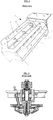
- Figure 1 describes a part of such an apparatus of the rotating type 1, wherein rotors 3 and flexible ducts 2 through which the fluid is fed, (glue in this case) are highlighted. Always figure 1 shows the openings 4 which lead to rotors and through which the nebulization is cast.
- such a model foresees a sequence of rotors 3, forming a line one next to the other and which lead to an opening through which the glue is throw and such an opening is re-closable through a shutter (S) (see for example figure 6 ).
- the shutter (S) can be closed again automatically to avoid spurts and dropping of glue throughout the environment.
- the device 1 as shown in figure 4 or in figure 6 , is placed to a certain distance from the paper tape passing horizontally according to the arrow direction of figure 6 downwards.
- the distance between the paper tape and the rotor which casts the glue can be comprised preferably between 20mm and 25mm (even more preferably, ranges between 20mm and 23mm or between 20mm and 22mm are optimal) with an unwinding direction, and therefore of paper passage, from top downwards (see the arrow direction of figure 4 or figure 6 ).
- the producer as per figure 7 , recommends a distance of 18mm with an unwinding of paper from bottom upstream with the help of a carter placed behind the paper.
- figure 4 highlights that the centrifugal device is not coupled to a carter to the opposite side of the tape.
- the above-mentioned WEKO model is used, according to the invention, with a 2800 RPM speed, that is the rotating speed of rotors spraying the glue is fixed and not adjustable. Such a value is however optimal for obtaining correct spraying effects, eventually by increasing the flow rate and maintaining constant the rotation when the forward motion speed of the tape increases.
- centrifugal system eliminates the risks of obstructions completely, as there are no fixed nozzles. At most, obstructions of filters can occur but they can be replaced also in use, thus allowing to wash the dirty one for its reuse.
- the preferred rotation speed of rotors is approximately 2800 RPM.
- Such a speed is independent from the forward motion speed of the tape but, as already said, the flow rate can be varied, that is the glue feeding to said centrifugal device.
- centrifugal system is available, always produced by Weko, allowing to vary the speed rotation of rotors.
- the new system foresees the Hz variation in a range of 40 ⁇ 60 Hz.
- the new system allows to adjust these parameters by the control panel.
- the flow rate of glue is adjusted by a pump which feds the glue toward the aforementioned apparatus 1. Therefore, if the production speed increases, so the forward motion speed of the tape increases and it is possible to operate by increasing the flow rate and/or varying the rotating speed of rotors, in such a manner so as to maintain the sprayed glue amount fixed per square centimeter.
- the pump which feeds the centrifugal device is regulated on values ideal for balm. Therefore, the inverter which monitors the pump engine can be programmed in such a manner so as to allow to vary the pump speed depending on specific need, in the case of use of glue.
- a flexible tube 2 is foreseen, bringing the fluid to the rotor.
- the rotor as already said, is rotatable around an axis.
- the flexible tube 2 is connected to a feeding duct, which is equipped with an adjusting valve, that is said adjusting valve (not represented in figure 1 for the sake of simplicity).
- the 0,54mm diameter is a standard converting size. The need to increase the flow rate has led to such a selection of increased diameters, speeds of the current rewinder machineries permitting. Moreover, by using increased (heavier) bulks (types of paper), adjusting valves of bigger sizes will be necessary.
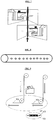
- figure 3 outlines a production line (rewinder machinery), wherein two paper tapes are glued each other, in such a manner so as to obtain a single two-ply tape which will form the two-ply mother roll.
- the arrangement of figure 3 is for the production of three or more plies and it is to be highlighted that the other gluing sections have been omitted for the sake of simplicity.
- a first mother roll 10 is highlighted, formed by a wound paper tape and from which such a tape 10 unwinds, which forms a first-ply of the tape.
- a ply of tape 100 is made pass in front of the centrifugal device 1, where the glue is sprayed along the horizontal length of the tape.
- FIG. 4 shows in details, as already said, the passage of paper in front of the apparatus 1.
- a second ply of the paper tape is unwound equally from a second reel 20, following his processing path itself.
- the glue is spread only on a side of a ply, attaching together the two plies subsequently. Instead, in the case of more plies, the glue is spread on a side of the first ply and on the opposite side of the subsequent ply (as in figure 3 ).
- figure 9 shows a machinery for the production of a glued two-ply tape, wherein only a centrifugal device is arranged, spraying on the side of a ply only, in such a manner that the glue layer (C1) is comprised between the two plies to glue them.
- the glue is spread onto the side of the first ply (V1) which glues to the second one (V2) and to the opposite side of the second ply (V2) which glues to the third one (V3).
- V1 glues to the second one
- V2 the opposite side of the second ply
- V3 glues to the third one
- the same sequence is repeated in the case of four or more plies, by spreading additional glue on the opposite side of the third ply which glue to the fourth one, etc.
- plies along the path are attached by gluing by overlapping one another as per prior art and then they are wound onto a single mother reel (see schematization in figures 9 and 10 ).
- any number of plies (even three or more) can be spread with glue and then they are overlapped one another.
- the used glue is preferably a traditional glue used in the specific technical field of "coverting paper". It is a polyvinyl alcohol based glue that must be used with certain dilutions, compatible with the centrifugal device.
- the dilution from 1:2 (two liters of water each liter of glue) to 1:10 (ten liters of water each liter of glue) range has proved to be optimal, depending on the glue supplier.
- the optimal dilution proves to be 1:5.
- the bought glue has to be diluted, according to the aforementioned dilutions.
- a continue agitation of the solution is necessary, as water and glue tend to separate themselves. Therefore, a preparation tank has been foreseen and it is placed close to the Weko machinery with an agitating system with a lower number of rotations than the preparation tub, to avoid the separation between glue and water.
- This second tank is linked to a feeding system, a pump for example, which feeds the diluted glue continuously, in such a manner so as to maintain the processing conditions stable.
- blowing system 50 to distance the paper from the section which sprays the glue by means of the described centrifugal device (see figure 6 ).
- a rod 50 has been added (simply made by a holed tube), wherein pressurized air flows. Holes are directed properly and work as nozzles.
- the rod is arranged in such a manner that the air flow intercepts the paper tape diagonally.
- the air pressure range may be between 0,05 bar to 1 bar, with a found optimal value of 0,15 bar.
- the air flow is continuous and is sent also during the normal operation of the machinery, that is while gluing. In this way, the air helps to conduct better the sprayed glue on the passing paper, thus allowing to obtain a double advantage. Moreover, air flows allow a more efficient gluing, because they prevent the dust from depositing onto the paper tape and the glue can have a better adherence on the paper itself.
- a containing tank 60 has been integrated below said section which sprays glue by centrifugal force (outlined in figure 6 ) .
- centrifugal system are used for conditioners and a potential conditioner excess is absorbed by paper. Instead, a potential glue excess causes the paper to rip.
- the glue system used in the paper factory operates in an environment different from those one for such converting centrifugal devices. For example, there is more dust in the paper factory. If it is dispersed in the environment, the glue together with dust forms clumps which stick to the various parts of the machine, thus spoiling its operation. For this reason, the tank 60 collecting the exceeding glue has been integrated, placed below the centrifugal device.
- the position can be optimized by placing the tank slightly backward with respect to the rotor itself, in order to collect as much glue as possible, thus facilitating the further cleaning and the maintenance. Therefore, if glue is collected, it will be held in the tub, even forming clumps together with dust, without the risk of dirtying other parts of the machinery or even the paper under production.
- a conditioner if a conditioner is used and it is sprayed onto rollers as paper has some defects (holes, rips or lacerations), no problems occur: the conditioner is reabsorbed by paper during the passage. Instead, in the case of glue, it is necessary to stop the supply, as the paper passing on the roller may cause the paper itself to rip, due to holes, as glue begins to stiffen.
- a controlling system has been integrated, in order to detect paper breakages or lacerations, such a technology is very well known in itself in the technical field of paper processing.
- Ultrasound and optical sensors have been placed in suitable points upstream the gluing section (also different sensors may be used, such as for example inductive optimal sensors, in the case of dark paper colorations).
- the aforementioned sensors are placed upstream the centrifugal device, along the unwinding path of the paper. Sensors are connected to the centrifugal device and, as they detect a hole or a laceration on paper, they send a signal for closing the shutter of the rotor, thus preventing the glue from being sprayed.
- the defective paper is removed by the operator, which lets an extra piece to the strips of "healthy” paper and starts again, making the shutter open from the panel.
- sensors can block the glue supply and/or block the operation of the whole production line.
- figure 5 shows the result obtained as the glue is sprayed onto a paper passing approximately 1200 meters per minute (extremely high speed).
- the figure shows a uniform distribution of nebulized drops which lay on the part of the passing tape.
- the preferred embodiment of the invention is destined for the paper production, preferably paper reels, but the interleaved towels production is not excluded.
Landscapes
- Engineering & Computer Science (AREA)
- Textile Engineering (AREA)
- Application Of Or Painting With Fluid Materials (AREA)
- Paper (AREA)
Claims (20)
- Ein Verfahren zur Herstellung eines Bandes mit zwei oder mehr geklebten Lagen, wobei das Verfahren die folgenden Phasen umfasst:- Das Zuführen von mindestens einer ersten Lage (100) in Form eines Bandes entlang eines ersten Verarbeitungsweges;- Das Zuführen von mindestens einer zweiten Lage (200) in Form eines Bandes entlang eines zweiten Verarbeitungsweges;- Die Verteilung des Klebematerials auf mindestens einer der beiden Lagen entlang des Verarbeitungsweges und das anschließende Übereinanderlegen der beiden genannten Lagen;- dadurch gekennzeichnet, dass der Verteilungsprozess des Klebstoffmaterials durch die Rotation mindestens eines Elementes der rotierenden Verteilung (3) erfolgt, dem das Klebstoffmaterial zugeführt wird und das durch Zentrifugalkraft eine Zerstäubung des genannten Klebstoffmaterials auf die in einem vorbestimmten Abstand von ihm angeordnete Lage vornimmt.
- Ein Verfahren gemäß Anspruch 1, bei dem die Erzeugung einer Gasströmung vorgesehen ist, die auf den Teil der Lage auftrifft, der vor dem Element der rotierenden Verteilung (3) angeordnet ist, vorzugsweise während des gesamten Herstellungsprozesses oder zumindest im Falle einer Blockierung der Zuführung der Lage/der Lagen.
- Ein Verfahren gemäß Anspruch 1 oder 2, bei dem während der Zuführung der Lagen durch geeignete Erfassungsmittel eine Analyse der Gesamtheit der Lagen selbst vor dem Teil durchgeführt wird, in dem die Klebephase stattfindet.
- Ein Verfahren gemäß einem oder mehreren der vorhergehenden Ansprüche, wobei der Prozess der Verteilung des Klebstoffmaterials durch die Anordnung einer Zentrifugalvorrichtung (1) erfolgt, die eine Vielzahl von Elementen der rotierenden Verteilung umfasst, die nahe beieinander so angeordnet sind, dass sie die durchlaufende Schicht horizontal abfangen.
- Ein Verfahren gemäß einem oder mehreren der vorhergehenden Ansprüche, bei dem der Abstand für die Anordnung jedes Elements der rotierenden Verteilung (3) in Bezug auf die durchlaufende Lage aus einem Bereich von 20 mm und 25 mm ausgewählt wird.
- Ein Verfahren gemäß einem oder mehreren der vorhergehenden Ansprüche, bei dem die Vorschubrichtung der Lage vor dem genannten Element der rotierenden Verteilung (3) von oben nach unten verläuft.
- Ein Verfahren gemäß einem oder mehreren der vorhergehenden Ansprüche, bei dem das durch das Element der rotierenden Verteilung (3) zugeführte Klebstoffmaterial mit einer anderen Flüssigkeit, vorzugsweise Wasser, verdünnt wird.
- Ein Verfahren gemäß Anspruch 7, bei dem der ausgewählte Verdünnungsklebstoff/die ausgewählte Verdünnungsflüssigkeit in einem Verhältnis von 1:2 bis 1:10, vorzugsweise 1:5, enthalten ist.
- Ein Verfahren gemäß einem oder mehreren der vorhergehenden Ansprüche, bei dem die Drehgeschwindigkeit des Elements der rotierenden Verteilung (3) einstellbar ist.
- Ein Verfahren gemäß einem oder mehreren der vorhergehenden Ansprüche, bei dem die Drehgeschwindigkeit des Elements der rotierenden Verteilung (3) zwischen 2400 U/min und 3600 U/min, vorzugsweise 2800 U/min oder ungefähr 3000 U/min, liegt.
- Eine Maschine zur Herstellung eines Endlosbandes mit einer oder mehreren geklebten Lagen, vorzugsweise eine Aufwickelmaschine, wobei die Maschine umfasst:- Mindestens einen ersten Zuführweg, durch den mindestens eine erste Lage (100) in Form eines Bandes zugeführt werden kann;- Mindestens einen zweiten Zuführweg, durch den mindestens eine zweite Lage (200) in Form eines Bandes zugeführt werden kann;- einen Klebebereich (1), um die Verteilung von Klebematerial auf mindestens einer der beiden Lagen im Durchlauf entlang seines Verarbeitungsweges zu ermöglichen, und zwar derart, dass die beiden Lagen miteinander verbunden werden können;- dadurch gekennzeichnet, dass der Klebebereich (1) mindestens ein Element der rotierenden Verteilung (3) umfasst, das so angeordnet ist, dass sich ein vorgegebener Abstand von der im Durchlauf befindlichen Lage ergibt und der es bei Verwendung des genannten Klebematerials zugeführt wird, und zwar so, dass eine Zerstäubung des genannten Klebematerials durch Zentrifugalkraft erfolgt.
- Eine Maschine gemäß Anspruch 11, bei der eine Vorrichtung zur Erzeugung einer Gasströmung (50) enthalten ist, die so angeordnet ist, dass sie mit der erzeugten Strömung auf den Teil der Lage treffen kann, der vor dem Element der rotierenden Verteilung (3) angeordnet ist.
- Eine Maschine gemäß Anspruch 11 oder 12, bei der ein oder mehrere Erfassungssensoren vor dem Klebebereich (1) vorgesehen und angeordnet sind und so konfiguriert sind, dass sie potenzielle Risse oder Löcher im Band überprüfen.
- Eine Maschine gemäß einem oder mehreren der vorhergehenden Ansprüche 11 bis 13, bei der der Abstand zur Anordnung des Elements der rotierenden Verteilung (3) in Bezug auf die durchlaufende Lage in einem Bereich zwischen 20 mm und 25 mm gewählt wird.
- Eine Maschine gemäß einem oder mehreren der vorhergehenden Ansprüche 11 bis 14, bei der die Richtung der Lage vor dem genannten Element der rotierenden Verteilung (3) von oben nach unten verläuft.
- Eine Maschine gemäß einem oder mehreren der vorhergehenden Ansprüche 11 bis 15, bei der mindestens zwei voneinander beabstandete Rollen vorhanden sind, die den Durchlauf des Bandes vor dem Element der rotierenden Verteilung (3) von oben nach unten bilden.
- Eine Maschine gemäß einem oder mehreren der vorhergehenden Ansprüche 11 bis 16, bei der ein Behälter zur Aufnahme von Klebstoff enthalten ist, der mit einem Rührer und einem Pumpsystem zum Pumpen von Klebstoffmaterial zum Element der rotierenden Verteilung (3) mit variabler Strömungsrate ausgestattet ist.
- Eine Maschine gemäß einem oder mehreren der vorhergehenden Ansprüche 11 bis 17, bei der ein Regelventil mit einem Durchmesser von ungefähr 1 mm für jedes Element der rotierenden Verteilung (3) vorgesehen ist.
- Eine Maschine gemäß einem oder mehreren der vorhergehenden Ansprüche 11 bis 18c, bei der die Drehgeschwindigkeit des Elements der rotierenden Verteilung (3) zwischen 2400 U/min und 3600 U/min, vorzugsweise zwischen 2800 U/min und 3000 U/min, noch besser bei 2800 U/min liegt.
- Die Verwendung einer Zentrifugalvorrichtung (1) mit mindestens einem Element der rotierenden Verteilung(3), das durch Zentrifugalkraft die Zerstäubung eines Klebematerials vornimmt, um ein Band mit zwei oder mehr Klebelagen herzustellen.
Applications Claiming Priority (1)
| Application Number | Priority Date | Filing Date | Title |
|---|---|---|---|
| PCT/IT2017/000058 WO2018173079A1 (en) | 2017-03-22 | 2017-03-22 | A method for producing glued reels with two or more plies and related machinery |
Publications (2)
| Publication Number | Publication Date |
|---|---|
| EP3601124A1 EP3601124A1 (de) | 2020-02-05 |
| EP3601124B1 true EP3601124B1 (de) | 2020-06-24 |
Family
ID=59093594
Family Applications (1)
| Application Number | Title | Priority Date | Filing Date |
|---|---|---|---|
| EP17731952.2A Active EP3601124B1 (de) | 2017-03-22 | 2017-03-22 | Verfahren zur herstellung von geklebten rollen mit zwei oder mehr lagen und diesbezügliche maschinen |
Country Status (2)
| Country | Link |
|---|---|
| EP (1) | EP3601124B1 (de) |
| WO (1) | WO2018173079A1 (de) |
Families Citing this family (2)
| Publication number | Priority date | Publication date | Assignee | Title |
|---|---|---|---|---|
| CN112777401B (zh) * | 2020-06-01 | 2024-04-16 | 张家港伟诺复合材料有限公司 | 一种碳纤维布生产工艺及其改进型收丝装置 |
| CN115976846B (zh) * | 2022-12-20 | 2024-12-10 | 深圳全棉时代科技有限公司 | 一种全棉双层速干保暖面料及其制备方法 |
Family Cites Families (3)
| Publication number | Priority date | Publication date | Assignee | Title |
|---|---|---|---|---|
| US3749315A (en) * | 1972-06-23 | 1973-07-31 | Crathern Eng | Centrifugal dispensing device |
| DE3529675A1 (de) * | 1985-08-20 | 1987-03-05 | Hesselmann Planatolwerk H | Vorrichtung zum punktfoermigen auftrag von klebstoff auf sehr schnellbewegte bahnen |
| DE4003577C1 (de) * | 1990-01-31 | 1991-04-25 | Grafotec Kotterer Gmbh, 8901 Diedorf, De |
-
2017
- 2017-03-22 EP EP17731952.2A patent/EP3601124B1/de active Active
- 2017-03-22 WO PCT/IT2017/000058 patent/WO2018173079A1/en not_active Ceased
Non-Patent Citations (1)
| Title |
|---|
| None * |
Also Published As
| Publication number | Publication date |
|---|---|
| WO2018173079A1 (en) | 2018-09-27 |
| EP3601124A1 (de) | 2020-02-05 |
Similar Documents
| Publication | Publication Date | Title |
|---|---|---|
| KR100426387B1 (ko) | 이동중인종이또는카드보드웹을피복시키는방법및장치 | |
| JP4955866B2 (ja) | 被覆紙テープ上に接着剤を塗布するための方法 | |
| KR101885399B1 (ko) | 두루마리 화장지 제품의 제조 방법 및 두루마리 화장지 제품 | |
| US6410100B1 (en) | Method of applying a coating medium on a traveling fiber material web | |
| JP3205935B2 (ja) | ロール巻取装置及び方法 | |
| EP0441019B1 (de) | System zum Waschen eines Gummituches mit einer Sprühvorrichtung | |
| JP4681677B1 (ja) | ティシュペーパー製品用二次原反ロールの製造方法及びティシュペーパー製品の製造方法 | |
| EP2772584A1 (de) | Verfahren und Anordnung für einen Fasernetzproduktionslinie | |
| US6045085A (en) | Adhesive dispensing device in a reel-up in a paper machine | |
| US2766720A (en) | Air doctor for web coating machines | |
| AU2002212919A1 (en) | Adhesive dispenser in a reel-up in a paper machine | |
| EP3601124A1 (de) | Verfahren zur herstellung von geklebten rollen mit zwei oder mehr lagen und diesbezügliche maschinen | |
| US6253818B1 (en) | Device for changing reels at paper machines | |
| CN202697694U (zh) | 用于连续纸幅的涂胶单元 | |
| CN210596572U (zh) | 一种纺织用纺织布加湿装置 | |
| KR20200011543A (ko) | 접착제를 이동중인 웹에 적용하기 위한 시스템 및 공정 | |
| JP2592583B2 (ja) | 材料ウェブロールを包装する方法及び装置 | |
| CA2222891C (en) | Apparatus and method of fabric cleaning | |
| JP2002017601A (ja) | おしぼり製造装置 | |
| EP4085169B1 (de) | Verfahren und vorrichtung für die produktion von tissue-papier | |
| WO2014192980A4 (ja) | 液体適用装置及び液体適用方法 | |
| KR102328514B1 (ko) | 이동중인 베이스 웹 상에 있는 접착제 패턴 | |
| CA2147094A1 (en) | Apparatus for the application of at least one liquid medium onto a moving material web | |
| US20110301007A1 (en) | Device and method for the production of tubes or sections of tubes | |
| KR20080083258A (ko) | 기재에 접착제 실과 포인트를 도포하기 위한 방법과 장치,접착제 실로 구성된 플리스와 층을 포함하는 재료 웨브, 및이 웨브로 만들어진 제품 |
Legal Events
| Date | Code | Title | Description |
|---|---|---|---|
| STAA | Information on the status of an ep patent application or granted ep patent |
Free format text: STATUS: UNKNOWN |
|
| STAA | Information on the status of an ep patent application or granted ep patent |
Free format text: STATUS: THE INTERNATIONAL PUBLICATION HAS BEEN MADE |
|
| PUAI | Public reference made under article 153(3) epc to a published international application that has entered the european phase |
Free format text: ORIGINAL CODE: 0009012 |
|
| STAA | Information on the status of an ep patent application or granted ep patent |
Free format text: STATUS: REQUEST FOR EXAMINATION WAS MADE |
|
| 17P | Request for examination filed |
Effective date: 20191002 |
|
| AK | Designated contracting states |
Kind code of ref document: A1 Designated state(s): AL AT BE BG CH CY CZ DE DK EE ES FI FR GB GR HR HU IE IS IT LI LT LU LV MC MK MT NL NO PL PT RO RS SE SI SK SM TR |
|
| AX | Request for extension of the european patent |
Extension state: BA ME |
|
| GRAP | Despatch of communication of intention to grant a patent |
Free format text: ORIGINAL CODE: EPIDOSNIGR1 |
|
| STAA | Information on the status of an ep patent application or granted ep patent |
Free format text: STATUS: GRANT OF PATENT IS INTENDED |
|
| INTG | Intention to grant announced |
Effective date: 20200330 |
|
| GRAS | Grant fee paid |
Free format text: ORIGINAL CODE: EPIDOSNIGR3 |
|
| GRAA | (expected) grant |
Free format text: ORIGINAL CODE: 0009210 |
|
| STAA | Information on the status of an ep patent application or granted ep patent |
Free format text: STATUS: THE PATENT HAS BEEN GRANTED |
|
| AK | Designated contracting states |
Kind code of ref document: B1 Designated state(s): AL AT BE BG CH CY CZ DE DK EE ES FI FR GB GR HR HU IE IS IT LI LT LU LV MC MK MT NL NO PL PT RO RS SE SI SK SM TR |
|
| AX | Request for extension of the european patent |
Extension state: BA ME |
|
| DAV | Request for validation of the european patent (deleted) | ||
| REG | Reference to a national code |
Ref country code: GB Ref legal event code: FG4D |
|
| REG | Reference to a national code |
Ref country code: CH Ref legal event code: EP |
|
| REG | Reference to a national code |
Ref country code: DE Ref legal event code: R096 Ref document number: 602017018704 Country of ref document: DE |
|
| REG | Reference to a national code |
Ref country code: AT Ref legal event code: REF Ref document number: 1283706 Country of ref document: AT Kind code of ref document: T Effective date: 20200715 |
|
| REG | Reference to a national code |
Ref country code: IE Ref legal event code: FG4D |
|
| PG25 | Lapsed in a contracting state [announced via postgrant information from national office to epo] |
Ref country code: SE Free format text: LAPSE BECAUSE OF FAILURE TO SUBMIT A TRANSLATION OF THE DESCRIPTION OR TO PAY THE FEE WITHIN THE PRESCRIBED TIME-LIMIT Effective date: 20200624 Ref country code: NO Free format text: LAPSE BECAUSE OF FAILURE TO SUBMIT A TRANSLATION OF THE DESCRIPTION OR TO PAY THE FEE WITHIN THE PRESCRIBED TIME-LIMIT Effective date: 20200924 Ref country code: FI Free format text: LAPSE BECAUSE OF FAILURE TO SUBMIT A TRANSLATION OF THE DESCRIPTION OR TO PAY THE FEE WITHIN THE PRESCRIBED TIME-LIMIT Effective date: 20200624 Ref country code: GR Free format text: LAPSE BECAUSE OF FAILURE TO SUBMIT A TRANSLATION OF THE DESCRIPTION OR TO PAY THE FEE WITHIN THE PRESCRIBED TIME-LIMIT Effective date: 20200925 Ref country code: LT Free format text: LAPSE BECAUSE OF FAILURE TO SUBMIT A TRANSLATION OF THE DESCRIPTION OR TO PAY THE FEE WITHIN THE PRESCRIBED TIME-LIMIT Effective date: 20200624 |
|
| REG | Reference to a national code |
Ref country code: LT Ref legal event code: MG4D |
|
| PG25 | Lapsed in a contracting state [announced via postgrant information from national office to epo] |
Ref country code: LV Free format text: LAPSE BECAUSE OF FAILURE TO SUBMIT A TRANSLATION OF THE DESCRIPTION OR TO PAY THE FEE WITHIN THE PRESCRIBED TIME-LIMIT Effective date: 20200624 Ref country code: HR Free format text: LAPSE BECAUSE OF FAILURE TO SUBMIT A TRANSLATION OF THE DESCRIPTION OR TO PAY THE FEE WITHIN THE PRESCRIBED TIME-LIMIT Effective date: 20200624 Ref country code: RS Free format text: LAPSE BECAUSE OF FAILURE TO SUBMIT A TRANSLATION OF THE DESCRIPTION OR TO PAY THE FEE WITHIN THE PRESCRIBED TIME-LIMIT Effective date: 20200624 Ref country code: BG Free format text: LAPSE BECAUSE OF FAILURE TO SUBMIT A TRANSLATION OF THE DESCRIPTION OR TO PAY THE FEE WITHIN THE PRESCRIBED TIME-LIMIT Effective date: 20200924 |
|
| REG | Reference to a national code |
Ref country code: NL Ref legal event code: MP Effective date: 20200624 |
|
| REG | Reference to a national code |
Ref country code: AT Ref legal event code: MK05 Ref document number: 1283706 Country of ref document: AT Kind code of ref document: T Effective date: 20200624 |
|
| PG25 | Lapsed in a contracting state [announced via postgrant information from national office to epo] |
Ref country code: NL Free format text: LAPSE BECAUSE OF FAILURE TO SUBMIT A TRANSLATION OF THE DESCRIPTION OR TO PAY THE FEE WITHIN THE PRESCRIBED TIME-LIMIT Effective date: 20200624 Ref country code: AL Free format text: LAPSE BECAUSE OF FAILURE TO SUBMIT A TRANSLATION OF THE DESCRIPTION OR TO PAY THE FEE WITHIN THE PRESCRIBED TIME-LIMIT Effective date: 20200624 |
|
| PG25 | Lapsed in a contracting state [announced via postgrant information from national office to epo] |
Ref country code: CZ Free format text: LAPSE BECAUSE OF FAILURE TO SUBMIT A TRANSLATION OF THE DESCRIPTION OR TO PAY THE FEE WITHIN THE PRESCRIBED TIME-LIMIT Effective date: 20200624 Ref country code: RO Free format text: LAPSE BECAUSE OF FAILURE TO SUBMIT A TRANSLATION OF THE DESCRIPTION OR TO PAY THE FEE WITHIN THE PRESCRIBED TIME-LIMIT Effective date: 20200624 Ref country code: EE Free format text: LAPSE BECAUSE OF FAILURE TO SUBMIT A TRANSLATION OF THE DESCRIPTION OR TO PAY THE FEE WITHIN THE PRESCRIBED TIME-LIMIT Effective date: 20200624 Ref country code: SM Free format text: LAPSE BECAUSE OF FAILURE TO SUBMIT A TRANSLATION OF THE DESCRIPTION OR TO PAY THE FEE WITHIN THE PRESCRIBED TIME-LIMIT Effective date: 20200624 Ref country code: AT Free format text: LAPSE BECAUSE OF FAILURE TO SUBMIT A TRANSLATION OF THE DESCRIPTION OR TO PAY THE FEE WITHIN THE PRESCRIBED TIME-LIMIT Effective date: 20200624 Ref country code: ES Free format text: LAPSE BECAUSE OF FAILURE TO SUBMIT A TRANSLATION OF THE DESCRIPTION OR TO PAY THE FEE WITHIN THE PRESCRIBED TIME-LIMIT Effective date: 20200624 Ref country code: PT Free format text: LAPSE BECAUSE OF FAILURE TO SUBMIT A TRANSLATION OF THE DESCRIPTION OR TO PAY THE FEE WITHIN THE PRESCRIBED TIME-LIMIT Effective date: 20201026 |
|
| PG25 | Lapsed in a contracting state [announced via postgrant information from national office to epo] |
Ref country code: SK Free format text: LAPSE BECAUSE OF FAILURE TO SUBMIT A TRANSLATION OF THE DESCRIPTION OR TO PAY THE FEE WITHIN THE PRESCRIBED TIME-LIMIT Effective date: 20200624 Ref country code: PL Free format text: LAPSE BECAUSE OF FAILURE TO SUBMIT A TRANSLATION OF THE DESCRIPTION OR TO PAY THE FEE WITHIN THE PRESCRIBED TIME-LIMIT Effective date: 20200624 Ref country code: IS Free format text: LAPSE BECAUSE OF FAILURE TO SUBMIT A TRANSLATION OF THE DESCRIPTION OR TO PAY THE FEE WITHIN THE PRESCRIBED TIME-LIMIT Effective date: 20201024 |
|
| REG | Reference to a national code |
Ref country code: DE Ref legal event code: R097 Ref document number: 602017018704 Country of ref document: DE |
|
| PG25 | Lapsed in a contracting state [announced via postgrant information from national office to epo] |
Ref country code: DK Free format text: LAPSE BECAUSE OF FAILURE TO SUBMIT A TRANSLATION OF THE DESCRIPTION OR TO PAY THE FEE WITHIN THE PRESCRIBED TIME-LIMIT Effective date: 20200624 |
|
| PLBE | No opposition filed within time limit |
Free format text: ORIGINAL CODE: 0009261 |
|
| STAA | Information on the status of an ep patent application or granted ep patent |
Free format text: STATUS: NO OPPOSITION FILED WITHIN TIME LIMIT |
|
| 26N | No opposition filed |
Effective date: 20210325 |
|
| PG25 | Lapsed in a contracting state [announced via postgrant information from national office to epo] |
Ref country code: MC Free format text: LAPSE BECAUSE OF FAILURE TO SUBMIT A TRANSLATION OF THE DESCRIPTION OR TO PAY THE FEE WITHIN THE PRESCRIBED TIME-LIMIT Effective date: 20200624 |
|
| REG | Reference to a national code |
Ref country code: CH Ref legal event code: PL |
|
| GBPC | Gb: european patent ceased through non-payment of renewal fee |
Effective date: 20210322 |
|
| REG | Reference to a national code |
Ref country code: BE Ref legal event code: MM Effective date: 20210331 |
|
| PG25 | Lapsed in a contracting state [announced via postgrant information from national office to epo] |
Ref country code: LI Free format text: LAPSE BECAUSE OF NON-PAYMENT OF DUE FEES Effective date: 20210331 Ref country code: LU Free format text: LAPSE BECAUSE OF NON-PAYMENT OF DUE FEES Effective date: 20210322 Ref country code: CH Free format text: LAPSE BECAUSE OF NON-PAYMENT OF DUE FEES Effective date: 20210331 Ref country code: IE Free format text: LAPSE BECAUSE OF NON-PAYMENT OF DUE FEES Effective date: 20210322 Ref country code: FR Free format text: LAPSE BECAUSE OF NON-PAYMENT OF DUE FEES Effective date: 20210331 Ref country code: GB Free format text: LAPSE BECAUSE OF NON-PAYMENT OF DUE FEES Effective date: 20210322 |
|
| PGFP | Annual fee paid to national office [announced via postgrant information from national office to epo] |
Ref country code: DE Payment date: 20220315 Year of fee payment: 6 |
|
| PGFP | Annual fee paid to national office [announced via postgrant information from national office to epo] |
Ref country code: IT Payment date: 20220224 Year of fee payment: 6 |
|
| PG25 | Lapsed in a contracting state [announced via postgrant information from national office to epo] |
Ref country code: BE Free format text: LAPSE BECAUSE OF NON-PAYMENT OF DUE FEES Effective date: 20210331 |
|
| PG25 | Lapsed in a contracting state [announced via postgrant information from national office to epo] |
Ref country code: CY Free format text: LAPSE BECAUSE OF FAILURE TO SUBMIT A TRANSLATION OF THE DESCRIPTION OR TO PAY THE FEE WITHIN THE PRESCRIBED TIME-LIMIT Effective date: 20200624 |
|
| PG25 | Lapsed in a contracting state [announced via postgrant information from national office to epo] |
Ref country code: HU Free format text: LAPSE BECAUSE OF FAILURE TO SUBMIT A TRANSLATION OF THE DESCRIPTION OR TO PAY THE FEE WITHIN THE PRESCRIBED TIME-LIMIT; INVALID AB INITIO Effective date: 20170322 |
|
| PG25 | Lapsed in a contracting state [announced via postgrant information from national office to epo] |
Ref country code: SI Free format text: LAPSE BECAUSE OF FAILURE TO SUBMIT A TRANSLATION OF THE DESCRIPTION OR TO PAY THE FEE WITHIN THE PRESCRIBED TIME-LIMIT Effective date: 20200624 |
|
| REG | Reference to a national code |
Ref country code: DE Ref legal event code: R119 Ref document number: 602017018704 Country of ref document: DE |
|
| PG25 | Lapsed in a contracting state [announced via postgrant information from national office to epo] |
Ref country code: DE Free format text: LAPSE BECAUSE OF NON-PAYMENT OF DUE FEES Effective date: 20231003 |
|
| PG25 | Lapsed in a contracting state [announced via postgrant information from national office to epo] |
Ref country code: MK Free format text: LAPSE BECAUSE OF FAILURE TO SUBMIT A TRANSLATION OF THE DESCRIPTION OR TO PAY THE FEE WITHIN THE PRESCRIBED TIME-LIMIT Effective date: 20200624 Ref country code: IT Free format text: LAPSE BECAUSE OF NON-PAYMENT OF DUE FEES Effective date: 20230322 |
|
| PG25 | Lapsed in a contracting state [announced via postgrant information from national office to epo] |
Ref country code: TR Free format text: LAPSE BECAUSE OF FAILURE TO SUBMIT A TRANSLATION OF THE DESCRIPTION OR TO PAY THE FEE WITHIN THE PRESCRIBED TIME-LIMIT Effective date: 20200624 |
|
| PG25 | Lapsed in a contracting state [announced via postgrant information from national office to epo] |
Ref country code: MT Free format text: LAPSE BECAUSE OF FAILURE TO SUBMIT A TRANSLATION OF THE DESCRIPTION OR TO PAY THE FEE WITHIN THE PRESCRIBED TIME-LIMIT Effective date: 20200624 |