EP3601149B1 - Gerät zum kühlen und entleeren einer metallischen getränkedose - Google Patents
Gerät zum kühlen und entleeren einer metallischen getränkedose Download PDFInfo
- Publication number
- EP3601149B1 EP3601149B1 EP18706815.0A EP18706815A EP3601149B1 EP 3601149 B1 EP3601149 B1 EP 3601149B1 EP 18706815 A EP18706815 A EP 18706815A EP 3601149 B1 EP3601149 B1 EP 3601149B1
- Authority
- EP
- European Patent Office
- Prior art keywords
- agitator
- towards
- tube
- machine
- integral
- Prior art date
- Legal status (The legal status is an assumption and is not a legal conclusion. Google has not performed a legal analysis and makes no representation as to the accuracy of the status listed.)
- Active
Links
Images




Classifications
-
- B—PERFORMING OPERATIONS; TRANSPORTING
- B67—OPENING, CLOSING OR CLEANING BOTTLES, JARS OR SIMILAR CONTAINERS; LIQUID HANDLING
- B67B—APPLYING CLOSURE MEMBERS TO BOTTLES JARS, OR SIMILAR CONTAINERS; OPENING CLOSED CONTAINERS
- B67B7/00—Hand- or power-operated devices for opening closed containers
- B67B7/24—Hole-piercing devices
- B67B7/26—Hole-piercing devices combined with spouts
- B67B7/28—Hole-piercing devices combined with spouts and associated with receptacle hodlers
-
- B—PERFORMING OPERATIONS; TRANSPORTING
- B67—OPENING, CLOSING OR CLEANING BOTTLES, JARS OR SIMILAR CONTAINERS; LIQUID HANDLING
- B67C—CLEANING, FILLING WITH LIQUIDS OR SEMILIQUIDS, OR EMPTYING, OF BOTTLES, JARS, CANS, CASKS, BARRELS, OR SIMILAR CONTAINERS, NOT OTHERWISE PROVIDED FOR; FUNNELS
- B67C9/00—Devices for emptying bottles, not otherwise provided for
-
- B—PERFORMING OPERATIONS; TRANSPORTING
- B67—OPENING, CLOSING OR CLEANING BOTTLES, JARS OR SIMILAR CONTAINERS; LIQUID HANDLING
- B67D—DISPENSING, DELIVERING OR TRANSFERRING LIQUIDS, NOT OTHERWISE PROVIDED FOR
- B67D1/00—Apparatus or devices for dispensing beverages on draught
- B67D1/0003—Apparatus or devices for dispensing beverages on draught the beverage being a single liquid
- B67D1/0004—Apparatus or devices for dispensing beverages on draught the beverage being a single liquid the beverage being stored in a container, e.g. bottle, cartridge, bag-in-box, bowl
-
- B—PERFORMING OPERATIONS; TRANSPORTING
- B67—OPENING, CLOSING OR CLEANING BOTTLES, JARS OR SIMILAR CONTAINERS; LIQUID HANDLING
- B67D—DISPENSING, DELIVERING OR TRANSFERRING LIQUIDS, NOT OTHERWISE PROVIDED FOR
- B67D1/00—Apparatus or devices for dispensing beverages on draught
- B67D1/08—Details
- B67D1/0857—Cooling arrangements
-
- B—PERFORMING OPERATIONS; TRANSPORTING
- B67—OPENING, CLOSING OR CLEANING BOTTLES, JARS OR SIMILAR CONTAINERS; LIQUID HANDLING
- B67D—DISPENSING, DELIVERING OR TRANSFERRING LIQUIDS, NOT OTHERWISE PROVIDED FOR
- B67D1/00—Apparatus or devices for dispensing beverages on draught
- B67D1/08—Details
- B67D1/0889—Supports
- B67D1/0891—Supports for the beverage container
-
- B—PERFORMING OPERATIONS; TRANSPORTING
- B67—OPENING, CLOSING OR CLEANING BOTTLES, JARS OR SIMILAR CONTAINERS; LIQUID HANDLING
- B67D—DISPENSING, DELIVERING OR TRANSFERRING LIQUIDS, NOT OTHERWISE PROVIDED FOR
- B67D3/00—Apparatus or devices for controlling flow of liquids under gravity from storage containers for dispensing purposes
- B67D3/0029—Apparatus or devices for controlling flow of liquids under gravity from storage containers for dispensing purposes provided with holders for bottles or similar containers
- B67D3/0035—Apparatus or devices for controlling flow of liquids under gravity from storage containers for dispensing purposes provided with holders for bottles or similar containers the bottle or container being held upside down and not provided with a closure, e.g. a bottle screwed onto a base of a dispenser
-
- B—PERFORMING OPERATIONS; TRANSPORTING
- B67—OPENING, CLOSING OR CLEANING BOTTLES, JARS OR SIMILAR CONTAINERS; LIQUID HANDLING
- B67D—DISPENSING, DELIVERING OR TRANSFERRING LIQUIDS, NOT OTHERWISE PROVIDED FOR
- B67D3/00—Apparatus or devices for controlling flow of liquids under gravity from storage containers for dispensing purposes
- B67D3/0058—Details
- B67D3/008—Supports
- B67D3/0083—Supports for the liquid container
-
- B—PERFORMING OPERATIONS; TRANSPORTING
- B67—OPENING, CLOSING OR CLEANING BOTTLES, JARS OR SIMILAR CONTAINERS; LIQUID HANDLING
- B67D—DISPENSING, DELIVERING OR TRANSFERRING LIQUIDS, NOT OTHERWISE PROVIDED FOR
- B67D1/00—Apparatus or devices for dispensing beverages on draught
- B67D1/0042—Details of specific parts of the dispensers
- B67D1/0081—Dispensing valves
- B67D1/0082—Dispensing valves entirely mechanical
-
- B—PERFORMING OPERATIONS; TRANSPORTING
- B67—OPENING, CLOSING OR CLEANING BOTTLES, JARS OR SIMILAR CONTAINERS; LIQUID HANDLING
- B67D—DISPENSING, DELIVERING OR TRANSFERRING LIQUIDS, NOT OTHERWISE PROVIDED FOR
- B67D1/00—Apparatus or devices for dispensing beverages on draught
- B67D1/04—Apparatus utilising compressed air or other gas acting directly or indirectly on beverages in storage containers
- B67D1/0456—Siphons, i.e. beverage containers under gas pressure without supply of further pressurised gas during dispensing
-
- B—PERFORMING OPERATIONS; TRANSPORTING
- B67—OPENING, CLOSING OR CLEANING BOTTLES, JARS OR SIMILAR CONTAINERS; LIQUID HANDLING
- B67D—DISPENSING, DELIVERING OR TRANSFERRING LIQUIDS, NOT OTHERWISE PROVIDED FOR
- B67D1/00—Apparatus or devices for dispensing beverages on draught
- B67D1/08—Details
- B67D1/0857—Cooling arrangements
- B67D1/0858—Cooling arrangements using compression systems
- B67D1/0861—Cooling arrangements using compression systems the evaporator acting through an intermediate heat transfer means
-
- B—PERFORMING OPERATIONS; TRANSPORTING
- B67—OPENING, CLOSING OR CLEANING BOTTLES, JARS OR SIMILAR CONTAINERS; LIQUID HANDLING
- B67D—DISPENSING, DELIVERING OR TRANSFERRING LIQUIDS, NOT OTHERWISE PROVIDED FOR
- B67D1/00—Apparatus or devices for dispensing beverages on draught
- B67D1/08—Details
- B67D1/0857—Cooling arrangements
- B67D1/0869—Cooling arrangements using solid state elements, e.g. Peltier cells
-
- B—PERFORMING OPERATIONS; TRANSPORTING
- B67—OPENING, CLOSING OR CLEANING BOTTLES, JARS OR SIMILAR CONTAINERS; LIQUID HANDLING
- B67D—DISPENSING, DELIVERING OR TRANSFERRING LIQUIDS, NOT OTHERWISE PROVIDED FOR
- B67D1/00—Apparatus or devices for dispensing beverages on draught
- B67D1/08—Details
- B67D1/0888—Means comprising electronic circuitry (e.g. control panels, switching or controlling means)
-
- B—PERFORMING OPERATIONS; TRANSPORTING
- B67—OPENING, CLOSING OR CLEANING BOTTLES, JARS OR SIMILAR CONTAINERS; LIQUID HANDLING
- B67D—DISPENSING, DELIVERING OR TRANSFERRING LIQUIDS, NOT OTHERWISE PROVIDED FOR
- B67D3/00—Apparatus or devices for controlling flow of liquids under gravity from storage containers for dispensing purposes
- B67D3/0009—Apparatus or devices for controlling flow of liquids under gravity from storage containers for dispensing purposes provided with cooling arrangements
Definitions
- the invention relates to the consumption of beverages stored in metal cans, and in particular to the refrigeration and serving of such beverages.
- a machine according to the preamble of claim 1 is known from document WO 2007/081208 A1 .
- the invention aims to resolve one or more of these drawbacks.
- the invention aims in particular to make it possible to consume drinks from different cans under optimal conditions of freshness, even when the cans have not been cooled beforehand.
- the invention thus relates to a machine for cooling and emptying the contents of a metal beverage can, as defined in claim 1 attached.
- the invention also relates to the variants of the dependent claims. Those skilled in the art will understand that each of the characteristics of the dependent claims can be combined independently with the characteristics of an independent claim, without constituting an intermediate generalization.
- the invention provides a machine for cooling and emptying the contents of a metal beverage can according to claim 1.
- the machine comprises a refrigerated housing for receiving a can and cooling it at its periphery.
- the machine has a protruding tubing in the refrigerated housing to be able to penetrate a lid of the can and access the beverage contained in the can.
- the tubing delimits a bore intended for emptying the beverage contained in the can.
- the machine has a removable sub-assembly in order to be easily cleaned and to prevent the taste of a drink from being altered by the taste of a previous drink.
- the removable sub-assembly comprises a stirrer mounted to slide relative to the tubing so as to be able to pass through the bore.
- the agitator In a high position, the agitator is located above the upper edge of the tubing, in order to be able to agitate the drink and obtain a forced thermal convection in the can. The cooling time of the drink inside the can is thus significantly reduced. In low position, the agitator is located below the upper edge of the tubing, which avoids damaging it when the can is put in place with the cover pierced through the tubing. A conduit of the sub-assembly communicates with the bore of the tubing. This duct is selectively closed or released by a plug. Thus, the drink can initially be kept in the can while it is cooling and stirring, and then emptied out.
- the figure 1 is a perspective view of an exemplary implementation of an embodiment of a machine 1 according to the invention.
- a system of axes is illustrated on figure 1 .
- the X axis will define a longitudinal direction of machine 1
- the Y axis will define a transverse direction of machine 1
- the Z axis will define a vertical direction of machine 1.
- the machine 1 comprises a casing 10 masking most of its components.
- the machine 1 comprises a can receiving block 12.
- the can receiving block 12 has an upper opening providing access to a refrigerated housing 120.
- the refrigerated housing 120 is intended to receive a can storing a beverage.
- a cover 13 selectively makes it possible to cover or release the upper opening, to block or release access to the refrigerated housing 120.
- the machine 1 comprises a receiving base 16 for a glass in which the refrigerated beverage must be emptied.
- the machine 1 here also includes a lever 20 intended to move a beverage stirring and emptying sub-assembly.
- the machine 1 here also comprises a drawer 14, advantageously intended for the removal of a seal and a pipe with respect to the rest of the machine 1.
- the figure 2 is a front sectional view of the machine 1 of the figure 1 .
- the machine 1 comprises a refrigeration device 15.
- the refrigeration device 15 here includes a compressor 150 and cooling pipes 151.
- the compressor 150 is housed inside the casing 10 and is fixed to a frame 11 of the machine 1.
- the compressor 150 circulates in a manner known per se a refrigerant fluid through the cooling pipes 151.
- Other alternative cooling devices can be envisaged, for example cooling devices with Peltier modules.
- the cooling pipes 151 are wound around a cylindrical wall 121, delimiting the refrigerated housing 120.
- the generatrix of the cylindrical wall 121 is here vertical.
- a can 9 is here housed in the refrigerated housing 120.
- the can 9 is here placed in the housing 120 with its cover facing down.
- the bobbin cover 9 has a flange 91 in contact with a gasket 140 carried by the drawer 14.
- the seal 140 is here resiliently biased upwards by a spring 143.
- the machine 1 here comprises a sub-assembly 5 including a stirrer 3 and a plug 4.
- the stirrer 3 is positioned facing the cover of the can 9.
- the sub-assembly 5 is arranged vertically from the receiving base 16.
- the machine 1 further comprises an electronic card 17, here housed under the casing 10.
- the electronic card 17 carries a control circuit for the refrigeration device 15 and for a drive motor for the agitator 3.
- the figure 3 is a detailed perspective view of the machine 1 at the level of the receiving block 12 and of the drawer 14.
- the drawer 14 is slidably mounted relative to the casing 10 in the longitudinal direction.
- the drawer 14 has a support 144 in which the seal 140 is housed.
- the support 144 is here slidably mounted relative to the drawer 14 in a vertical direction.
- the seal 140 is for example made of elastomer.
- the support 144 is biased by the spring 143, interposed between this support 144 and the slide 14.
- the spring 143 is for example implemented in the form of a so-called Belleville washer.
- the drawer 14 has a pipe 141, vertical.
- the tube 141 passes through the seal 140, and is surrounded by this seal 140.
- the tube 141 defines a bore 142.
- the tube 141 protrudes into the refrigerated housing 120, so as to be able to interfere with the cover of the can 9.
- the use of a removable drawer 14 allows for example rinsing of the seal 140 and of the tubing 141.
- the figure 4 is a front sectional view of the machine 1 at the level of the refrigerated housing 120.
- the tubing 141 is advantageously designed to pierce the cover of the can 9 when the latter is pushed into the refrigerated housing 120.
- the upper edge of the tube 141 advantageously has the shape of a knife.
- the cover of the can 9 can also advantageously have a pre-cut in the shape of the tube 141 to facilitate piercing.
- the machine 1 advantageously comprises the cover 13 intended to selectively cover the upper opening of the refrigerated housing 120. In the covered position, the cover 13 promotes the maintenance of a low temperature in the refrigerated housing 120.
- the cover 13 has a first end 131 by means of which it is mounted to pivot with respect to the covering 10 along a horizontal axis.
- the cover 13 has a second end 132 provided with a gripping member 133.
- the cover 13 can thus be pivoted between a position where it covers the upper opening of the refrigerated housing 120, and a position where it releases access to this housing. refrigerated 120 for the introduction of a can 9.
- the cover 13 has a projecting part in the housing refrigerated 120, when the gripper 133 is urged to cause the cover 13 to cover the refrigerated housing 120.
- a latching mechanism can be provided so that the cover 13 can be held independently in the position of covering the refrigerated housing 120.
- the seal after piercing the cover of the can 9 is thus ensured both by its contact with the seal 140 (elastically deformable) and its contact with the tubing 141.
- the spring 143 promotes the extraction of the can 9 when opening the cover 13, by exerting an upward force on the can 9 through the seal 140.
- the spring 143 also promotes the sealing of the system by maintaining contact between bobbin 9 and seal 140.
- the figure 5 is a front sectional view of the machine 1 at the level of its removable sub-assembly 5.
- the agitator 3 forms the upper part of the removable sub-assembly 5, the stopper 4 forming the lower part of this removable sub-assembly 5 .
- the stirrer 3 comprises fins 30 intended to create a movement of the drink inside the can 9, when these fins 30 are rotated about a vertical axis.
- the fins 30 are here fixed to the end of a shaft 31.
- the shaft 31 is here a hollow shaft defining a duct in communication with the bore 142.
- the shaft 31 is here slidably mounted in the vertical direction with respect to to the pipe 141.
- the fit between the shaft 31 and the pipe 141 is such that the drink cannot flow between the periphery of the shaft 31 and the pipe 141.
- the hollow shaft 31 has an orifice outlet 312 in the lower part for emptying the drink, and an inlet orifice 311 in the upper part, to receive the drink from the can 9.
- the agitator 3 is slidably mounted in the pipe 141 in the vertical direction.
- the agitator 3 can thus slide to pass through the bore 142 to a high position (not shown) where it protrudes above the upper edge of this tube 141.
- the fins 30 are thus bathed in the drink inside the can 9.
- the agitator 3 can slide to an intermediate position shown in figure 5 , where the fins 30 are set back relative to the upper edge of the tube 141. In this position, the fins 30 are protected by the tube 141 against interference with the cover of the can 9, which may cause their alteration.
- Teeth 32 are formed at the outer periphery of the hollow shaft 31.
- the teeth 32 make it possible to drive in rotation along the vertical axis of the agitator 3, as detailed below.
- the stopper 4 is mounted to slide vertically with respect to the agitator 3.
- the stopper 4 comprises in particular a tubular part 43, guided in sliding in a groove 36 of the agitator 3.
- the stopper 4 further comprises an external flange 44, guided. in vertical sliding by means of vertical shafts 34 integral with the agitator 3.
- Return springs 35 are here positioned around the shafts 34, and urge the plug 4 according to a downward return force, applied to the collar 44.
- the stopper 4 comprises a piston 41.
- the piston 41 has a radial surface 42.
- the radial surface 42 comes into contact with a bearing surface 33 of the stirrer 3, in order to block the flow of the beverage.
- the piston 41 is moved away from the seat 33, so that the drink can flow along its radial surface 42, then flow along the seat 33 of the stirrer 3.
- the drink flows along the fins 30, passes through the conduit 31 and the tubular part 43 of the stopper 4.
- the drink empties into a glass positioned on the base 16.
- the flow of the drink is generally facilitated by the presence of pressurized gas inside the can 9.
- the tubular part 43 here forms an extension of the hollow shaft 31, in order to prevent splashing of beverage below the sub-assembly 5.
- the machine 1 comprises a gear, driven by a motor 21, and capable of driving the agitator 3 in rotation.
- the gear comprises in particular a toothed wheel 213.
- the toothed wheel 213 comprises an external toothing and an internal toothing.
- the machine 1 furthermore comprises a support 7, configured to define the vertical position of the sub-assembly 5 (in particular of the agitator 3) and configured to guide the agitator 3 in rotation about a vertical axis.
- the support 7 is mounted to slide along a vertical axis, on shafts 111 integral with the frame 11.
- the support 7 also carries stops 77 and 78, intended to actuate the opening of the stopper 4.
- the structure of the support 7 will be detailed later. .
- the figure 6 is a diagram of the kinematics of a certain number of components of the machine 1.
- the block for receiving the bobbin 12 is integral with the frame 11.
- the drawer 14 is mounted to slide in the longitudinal direction with respect to the frame 11.
- the seal 140 is slidably mounted in the vertical direction relative to the drawer 14 and resiliently returned to a high position by means of the spring 143.
- the motor 21 is fixed to the frame 11.
- the rotor of the motor 21 drives a toothed wheel 211 in rotation about a vertical axis.
- Another intermediate toothed wheel 212 is here mounted to rotate with respect to the frame 11 about a vertical axis.
- the intermediate toothed wheel 212 is rotated by the toothed wheel 211.
- the agitator 3 is mounted to slide vertically relative to the frame 11 and relative to the drawer 14. Depending on the vertical position of the agitator 3, the teeth 32 integral with the shaft 31 are rotated by the toothed wheel 213 or disengaged from the wheel 213. For the sake of simplicity, the toothed wheel 213 is not illustrated and the kinematic illustration of the figure 6 shows a direct engagement of the teeth 32 on the intermediate toothed wheel 212.
- the fins 30 of the agitator 3 are configured to pass through the bore 142 of the pipe 141.
- the support 7 comprises horizontal shafts 700.
- the horizontal shafts 700 are slidably mounted in a vertical direction on the shafts 111.
- the support 7 comprises two jaws 71 and 72 slidably mounted in the longitudinal direction on the horizontal shafts 700.
- the support 7 comprises two jaws 71 and 72 slidably mounted in the longitudinal direction on the horizontal shafts 700.
- the jaws 71 and 72 are resiliently returned to a position where they are pressed against one another, by means of non-referenced springs. In the position where the jaws 71 and 72 are pressed against one another, the jaws 71 and 72 define the vertical position of the agitator 3 and guide the agitator 3 in rotation about a vertical axis. By separating the jaws 71 and 72, a release position of the sub-assembly 5 is defined.
- the machine 1 furthermore comprises a mechanism 23 for vertical displacement of the support 7.
- the mechanism 23 comprises a vertical rack 230, integral with the support 7.
- the lever 20 is mounted to pivot about an axis transverse to the frame 11.
- the lever 20 comprises a shaft 200 and a toothed wheel 201 fixed to the shaft 200.
- the pivot axis of the lever 20 coincides with the axis of the toothed wheel 201.
- the toothed wheel 201 is engaged with the rack 230.
- the agitator 3 In maintaining the lever 20 at an intermediate level, the agitator 3 is positioned in its intermediate position, the fins 30 then being set back relative to the upper edge of the pipe 141. By lowering the lever 20, the agitator 3 is in its position. low position, corresponding to an opening of the cap 4.
- the plug 4 cooperates with the bearing surface 33 to block the flow through the hollow shaft 31, which corresponds to the high position and to the intermediate position of the agitator 3.
- the collar 44 interferes with the stops 77 and 78, which moves the piston of the stopper 4 away from the bearing 33, releasing the flow through the hollow shaft 31.
- the figure 7 is a top sectional view of the machine 1 at the gear level.
- the stirrer 3 is here in its high position.
- the teeth 32 are then engaged with the internal teeth of the toothed wheel 213.
- the agitator 3 is driven in rotation by means of the teeth 32, of the toothed wheel 213 and of the intermediate toothed wheel 212.
- the figure 8 is a perspective view of a certain number of components of the machine 1.
- the machine 1 comprises in particular a manual actuator 75, accessible from outside the casing 10.
- the actuator 75 can for example slide in a groove made. through the casing 10.
- the actuator 75 is intended to urge the support 7 to bring it into its position of release from the sub-assembly 5.
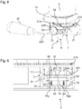
- the figure 9 is a side view of the support of the removable sub-assembly 5 in the guiding position, illustrating a mechanism 6 of the support 7 allowing it to pass from the guiding position of the sub-assembly 5 to its release position.
- the mechanism 6 comprises two pulleys 61 and 62 pivotally mounted on the support 7 around transverse axes.
- a belt 60 is wound around the pulleys 61 and 62.
- a stud 63 is integral with the upper strand of the belt 60.
- a protuberance 73 of the jaw 71 is fixed on the stud 63.
- a stud 64 is integral with the lower strand of the belt 60.
- a protuberance 74 of the jaw 72 is fixed to the stud 64.
- the protrusion 73 drives the stud 63 in the same translation.
- the pad 64 fixed on the opposite strand, is driven in translation in a direction opposite to the pad 63.
- the pad 64 thus drives the protuberance 74 and therefore the jaw 72 in translation in a direction opposite to that of the jaw 71.
- the stops 77 and 78 have an L-shape, and thus comprise a rod-shaped part, and one end forming a longitudinal protuberance.
- the stop 77 thus comprises a protuberance 770 at its lower end.
- the stop 78 has a protuberance 780 at its lower end.
- the jaw 71 is mounted to slide vertically with respect to the rod of the stop 77.
- the jaw 72 is mounted to slide vertically with respect to the rod of the stop 78.
- the stops 77 and 78 are integral in longitudinal sliding of the jaws 71 and 72 respectively. .
- the vertical position of the stops 77 and 78 is fixed relative to the frame 11.
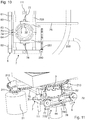
- the figures 10 and 11 are top and perspective views of the support 7 in its configuration for guiding the agitator 3 in rotation, and for maintaining the vertical position of the agitator 3.
- the agitator 3 is here in its intermediate position, the teeth 32 not being in engagement with the internal teeth of the toothed wheel 213.
- the jaws 71 and 72 are held pressed against one another by return forces, by means of springs not shown.
- the vertical position of the agitator 3 is ensured by a shoulder 37 formed on the outer periphery of the hollow shaft 31, interfering with the jaws 71 and 72.
- the protuberances 770 and 780 interfere with the collar 44, while the agitator 3 continues its downward stroke.
- the interference between the protuberances 770 and 780 and the flange 44 moves the bearing 33 away from the piston of the plug 4, releasing the flow through the hollow shaft 31.
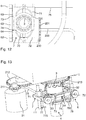
- the figures 12 and 13 are top and perspective views of the support 7 in its configuration for releasing the agitator 3 and the sub-assembly 5.
- the jaws 71 and 72 are spaced apart from each other. , to enlarge the opening 70 formed between the jaws 71 and 72.
- the jaws 71 and 72 release the agitator 3.
- the protuberances 770 and 780 are then sufficiently separated so as not to interfere with the collar 44. Consequently , the sub-assembly 5 is then free to slide vertically and can be removed from the machine 1. The sub-assembly 5 can then be easily cleaned.
- the support 7 provided with the jaws 71 and 72 biased by return springs advantageously allows a snap-together reassembly of the sub-assembly 5.
- the agitator 3 can be reintroduced by sliding through it. the opening 70 formed between the jaws 71 and 72.
- the shoulder 37 interferes with the jaws 71 and 72 in order to separate them.
- the shoulder 37 Once the shoulder 37 has passed the jaws 71 and 72, the latter are urged by the springs to narrow the opening 70 and come to be placed under the shoulder 37.
- the agitator 3 is then again held in a vertical position.
- the control circuit can implement a certain number of safeguards to avoid problems of use.
- a sensor can for example detect the high position of the agitator 3 or of the lever 20, and thus condition the drive of the agitator 3 by the motor 21 to this high position.
- the control circuit may include a time delay for the drive by the motor 21, corresponding to a sufficient duration for the cooling of the beverage in the can 9.
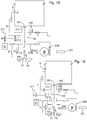
- the figures 14 to 19 illustrate the kinematics of the machine 1 for different phases of its operation. For the sake of readability, a number of components have not been illustrated.
- the figure 14 illustrates the machine 1 during the introduction of the can 9 into the refrigerated housing.
- the can 9 is brought into contact with the seal 140.
- the sub-assembly 5 is held by the jaws 71 and 72 of the support 7.
- the fins 30 of the agitator 3 are set back relative to the pipe 141, the agitator being maintained in its intermediate position by the lever 20.
- the teeth 32 of the agitator 3 are disengaged relative to the intermediate gear 212 and therefore relative to the motor 21.
- the figure 15 illustrates the machine 1 when closing the cover 13.
- the cover of the can 9 is then pierced by the tubing 141 and pushes the seal 140 down.
- the drink present inside the can flows through the hollow shaft 31 to the stopper 4 which is held in the closed position.
- the figure 16 illustrates machine 1 when lever 20 is raised.
- the jaws 71 and 72 of the support then slide upwards and cause the blades 30 of the agitator to slide upwards.
- the fins 30 then protrude above the pipe 141, inside the can 9.
- the agitator 3 is guided in rotation by the jaws 71 and 72.
- the teeth 32 are then engaged with the intermediate toothed wheel. 212.
- the motor 21 is then controlled to drive the fins 30 in rotation by means of the teeth 32.
- the plug 4 remains integral with the agitator 3 and maintained in its closed position.
- the figure 17 illustrates the machine 1 when the lever 20 is lowered.
- the drive in rotation of the motor 21 is interrupted beforehand and the teeth 32 are disengaged with respect to the intermediate toothed wheel 212.
- the fins 30 are positioned back inside the tubing 141.
- the flange 44 interferes with the stops 77 and 78 to drive the stopper 4 into its open position. The drink can then flow through the hollow shaft 31.
- the figure 18 illustrates the machine when the lever 20 is returned to a neutral position.
- the can 9 can be withdrawn from the refrigerated housing, and its cover slides relative to the pipe 141.
- the agitator 3 is in its intermediate position, and the stopper 4 has returned to its closed position.
- the figure 19 illustrates the machine during the withdrawal of the sub-assembly 5.
- the jaws 71 and 72 are moved away from each other, so that the sub-assembly 5 is no longer held by the jaws 71 72.
- the stops 77 and 78 are also spaced apart, so that the collar 44 no longer interferes with it. Consequently, the sub-assembly 5 can slide downwards by gravity or by a request from a user, and can therefore be separated from the rest of the machine 1, for rinsing with running water for example.
Landscapes
- Engineering & Computer Science (AREA)
- Mechanical Engineering (AREA)
- Devices For Dispensing Beverages (AREA)
- Apparatus For Making Beverages (AREA)
- Devices That Are Associated With Refrigeration Equipment (AREA)
Claims (14)
- Maschine (1), die zum Kühlen und Entleeren des Inhalts einer metallischen Getränkedose (9) bestimmt ist, wobei die Maschine umfasst:- ein gekühltes Gehäuse (120), das zur Aufnahme einer Dose bestimmt ist;- ein Rohr (141), das in das gekühlte Gehäuse (120) hineinragt und eine Bohrung (142) begrenzt, wobei die Maschine dadurch gekennzeichnet ist, dass sie umfasst:- eine abnehmbare Unterbaugruppe (5), einschließlich:- ein Getränkerührwerk (3), das in Bezug auf das Rohr (141) verschiebbar angebracht ist, um durch die Bohrung (142) zwischen einer oberen Position, in der es über den oberen Rand des Rohrs vorsteht, und einer Position, in der es in Bezug auf den oberen Rand des Rohrs zurückgesetzt ist, hindurchgehen zu können;- eine Leitung (31), die eine Auslassöffnung (312) und eine Einlassöffnung (311), die mit der Bohrung in Verbindung steht, aufweist;- einen Verschluss (4), der die Auslassöffnung der Leitung wahlweise verschließt oder freigibt.
- Maschine (1) nach Anspruch 1, die ferner eine Dichtung (140) umfasst, die in dem gekühlten Gehäuse (120) angeordnet ist und das Rohr (141) umgibt.
- Maschine (1) nach Anspruch 2, wobei die Dichtung (140) und das Rohr (141) in einer lösbaren Schublade (14) befestigt sind.
- Maschine (1) nach einem der vorhergehenden Ansprüche, wobei die Oberkante des Rohrs (141) ein Messer bildet.
- Maschine (1) nach einem der vorhergehenden Ansprüche, die ferner eine Kappe (13) umfasst, die mit einem ersten Ende (131) schwenkbar an einem oberen Ende des gekühlten Gehäuses (120) angebracht ist und ein Greifelement (133) an einem zweiten Ende (132) aufweist, wobei die Kappe einen Abschnitt aufweist, der in das gekühlte Gehäuse hineinragt, wenn das Greifelement gedrückt wird, um zu bewirken, dass die Kappe das gekühlte Gehäuse abdeckt.
- Maschine (1) nach einem der vorhergehenden Ansprüche, die einen Elektromotor (21) umfasst, der ein rotierendes Getriebe (211, 212, 213) antreibt, wobei das Rührwerk (3) mit dem Getriebe in der Position in Eingriff steht, in der es über den oberen Rand des vertikalen Rohrs (141) hinausragt und von diesem Getriebe in der Position gelöst ist, in der es von der Oberkante des vertikalen Rohrs zurückgesetzt ist.
- Maschine (1) nach Anspruch 6, wobei das Rührwerk (3) eine Hohlwelle (31) umfasst, die die Leitung begrenzt, wobei die Hohlwelle eine Verzahnung (32) aufweist, die selektiv in das Getriebe eingreift.
- Maschine (1) nach Anspruch 7, wobei das Rührwerk (3) Schaufeln (30) aufweist, die am oberen Ende der Hohlwelle (31) befestigt sind.
- Maschine (1) nach einem der vorhergehenden Ansprüche, die eine erste und eine zweite bewegliche Backe (71, 72) umfasst, die zwischen einer Position zur Drehführung der Unterbaugruppe (5) und einer Position zur Freigabe der vertikalen Verschiebung der Unterbaugruppe verschoben werden.
- Maschine (1) nach Anspruch 9, wobei die erste und die zweite bewegliche Backe (71, 72) elastisch in die Position zur Drehführung der Unterbaugruppe (5) gedrückt werden.
- Maschine (1) nach Anspruch 9 oder 10, die ferner umfasst:- ein Stellglied (75), das mit der ersten Backe (71) fest verbunden ist, um sie in ihre Freigabeposition des vertikalen Gleitens zu bringen;- einen Riemen (60) mit einem ersten Strang, der mit der ersten Backe aus einem Stück gebildet ist, und einem zweiten Strang, der mit der zweiten Backe (72) aus einem Stück gebildet ist.
- Maschine (1) nach einem der vorhergehenden Ansprüche, wobei:- der Verschluss (4) in Bezug auf die Leitung (31) zwischen einer Position, in der er die Austrittsöffnung verschließt, und einer Position, in der er die Austrittsöffnung freigibt, gleitend vertikal montiert ist, wobei der Verschluss (4) elastisch in Richtung der Position gedrückt wird, in der er die Austrittsöffnung freigibt;- das Rührwerk (3) mit der Leitung (31) aus einem Stück und in Bezug auf das vertikale Rohr (141) bis zu einer unteren Position gleitend montiert ist, in der es seinen Hub fortsetzen kann, wo aber der Verschluss mit einem Anschlag (770, 780) zusammenstößt, um sich in die Position zu bewegen, in der die Auslassöffnung freigegeben wird.
- Maschine (1) nach Anspruch 11 und Anspruch 12, wobei das Stellglied (75) mit dem Anschlag (770, 780) aus einem Stück gebildet ist, so dass der Anschlag nicht mehr mit dem Verschluss (4) zusammenstößt, wenn das Stellglied die erste Backe (71) in ihre vertikale gleitende Freigabeposition versetzt.
- Maschine (1) nach Anspruch 12 oder 13, die ferner einen Schwenkhebel (20) umfasst, der ein Zahnrad (201) in Drehung versetzt, wobei das Zahnrad (201) in eine mit dem Rührwerk (3) fest verbundene Zahnstange (230) eingreift, sodass das Schwenken des Hebels (20) in eine erste Position das Rührwerk in seine obere Position versetzt, das Schwenken des Hebels in eine zweite Stellung das Rührwerk in eine Zwischenstellung versetzt, in der es in Bezug auf die Oberkante des vertikalen Rohres (141) zurückgesetzt ist, das Schwenken des Hebels in eine dritte Stellung das Rührwerk (3) in die untere Stellung versetzt.
Applications Claiming Priority (2)
| Application Number | Priority Date | Filing Date | Title |
|---|---|---|---|
| FR1752532A FR3064259B1 (fr) | 2017-03-27 | 2017-03-27 | Machine destinee au refroidissement et au vidage du contenu d'une canette metallique de boisson |
| PCT/FR2018/050336 WO2018178527A1 (fr) | 2017-03-27 | 2018-02-13 | Machine destinee au refroidissement et au vidage du contenu d'une canette metallique de boisson |
Publications (2)
| Publication Number | Publication Date |
|---|---|
| EP3601149A1 EP3601149A1 (de) | 2020-02-05 |
| EP3601149B1 true EP3601149B1 (de) | 2021-03-31 |
Family
ID=58707891
Family Applications (1)
| Application Number | Title | Priority Date | Filing Date |
|---|---|---|---|
| EP18706815.0A Active EP3601149B1 (de) | 2017-03-27 | 2018-02-13 | Gerät zum kühlen und entleeren einer metallischen getränkedose |
Country Status (7)
| Country | Link |
|---|---|
| US (1) | US11072522B2 (de) |
| EP (1) | EP3601149B1 (de) |
| CN (1) | CN110546105B (de) |
| ES (1) | ES2870052T3 (de) |
| FR (1) | FR3064259B1 (de) |
| PT (1) | PT3601149T (de) |
| WO (1) | WO2018178527A1 (de) |
Families Citing this family (1)
| Publication number | Priority date | Publication date | Assignee | Title |
|---|---|---|---|---|
| CN114104557B (zh) * | 2021-12-10 | 2022-08-12 | 江苏集萃中科纳米科技有限公司 | 一种免疫诊断试剂自动回收架 |
Family Cites Families (16)
| Publication number | Priority date | Publication date | Assignee | Title |
|---|---|---|---|---|
| US1892547A (en) * | 1931-01-19 | 1932-12-27 | Richardson Corp | Beverage dispenser |
| US3926339A (en) * | 1974-06-21 | 1975-12-16 | Nat Can Corp | Liquid dispensing apparatus having plural can piercing tools |
| IT1257996B (it) * | 1991-01-16 | 1996-02-19 | Carpigiani Srl | Macchina combinata per la lavorazione di prodotti di gelateria e pasticceria. |
| US5797519A (en) | 1997-03-14 | 1998-08-25 | The Coca-Cola Company | Postmix beverage dispenser |
| DE19720553C2 (de) * | 1997-05-16 | 1999-07-15 | Kall Schanktechnik Gmbh | Getränkekühl- und -zapfgerät |
| CN2314323Y (zh) * | 1997-11-04 | 1999-04-14 | 魏辅唐 | 罐装饮料快速冷却器 |
| US20020089894A1 (en) * | 2001-01-08 | 2002-07-11 | Timothy Parlor | Device for storing, mixing and dispensing liquids |
| US6702153B2 (en) * | 2001-08-16 | 2004-03-09 | Food Equipment Technologies Company, Inc. | Beverage dispenser with faucet assembly |
| ZA200306098B (en) * | 2002-08-13 | 2003-10-15 | Protechna Sa | Withdrawal valve of plastics material for transportation and storage container for liquids. |
| MXPA06002172A (es) * | 2003-08-25 | 2006-05-22 | Henry Macler Ii | Enfriador portatil de agua con fluidos en bolsas. |
| NL1030883C1 (nl) * | 2006-01-10 | 2007-07-11 | 4Sight Innovation Bv | Inrichting voor het uit een blik tappen van een drank. |
| US20120204578A1 (en) * | 2010-12-09 | 2012-08-16 | Leavitt David D | Container Cap Containing Cooling Agent Insert |
| CN102662943B (zh) | 2012-01-18 | 2014-06-18 | 苏州酷动多媒体科技有限公司 | 短信匹配及去重方法 |
| JP5851281B2 (ja) * | 2012-02-28 | 2016-02-03 | 麒麟麦酒株式会社 | ディスペンサ |
| US8794485B2 (en) * | 2012-12-12 | 2014-08-05 | Malcolm Lunn | Frozen beverage dispenser |
| US10625223B2 (en) * | 2018-02-13 | 2020-04-21 | Green Shield Products, Llc | Mixer apparatus for mixing a high-viscosity fluid and mixer shaft for such mixer apparatus |
-
2017
- 2017-03-27 FR FR1752532A patent/FR3064259B1/fr not_active Expired - Fee Related
-
2018
- 2018-02-13 ES ES18706815T patent/ES2870052T3/es active Active
- 2018-02-13 CN CN201880021641.1A patent/CN110546105B/zh active Active
- 2018-02-13 EP EP18706815.0A patent/EP3601149B1/de active Active
- 2018-02-13 PT PT187068150T patent/PT3601149T/pt unknown
- 2018-02-13 WO PCT/FR2018/050336 patent/WO2018178527A1/fr not_active Ceased
- 2018-02-13 US US16/496,799 patent/US11072522B2/en active Active
Non-Patent Citations (1)
| Title |
|---|
| None * |
Also Published As
| Publication number | Publication date |
|---|---|
| US20200391991A1 (en) | 2020-12-17 |
| ES2870052T3 (es) | 2021-10-26 |
| EP3601149A1 (de) | 2020-02-05 |
| CN110546105A (zh) | 2019-12-06 |
| FR3064259B1 (fr) | 2019-04-19 |
| CN110546105B (zh) | 2021-03-05 |
| WO2018178527A1 (fr) | 2018-10-04 |
| US11072522B2 (en) | 2021-07-27 |
| FR3064259A1 (fr) | 2018-09-28 |
| PT3601149T (pt) | 2021-05-04 |
Similar Documents
| Publication | Publication Date | Title |
|---|---|---|
| RU2435712C2 (ru) | Машина для приготовления напитков | |
| EP1310199B1 (de) | Vorrichtung und Verfahren zum Selektieren und Extrahieren einer Kartusche für die Zubereitung eines Getränkes | |
| RU2431440C2 (ru) | Машина для приготовления напитков | |
| RU2435729C2 (ru) | Машина для приготовления напитков | |
| CA2472653C (fr) | Dispositif de production de boisson par infusion | |
| EP2083662B1 (de) | Anordnung mit einem gerät und einer einwegkapsel zur zubereitung eines brühgetränks und kapsel für eine derartige anordnung | |
| EP2679120B1 (de) | Gerät und Kapsel zur Herstellung eines Getränks | |
| EP0352689A1 (de) | Vorrichtung für biologische Analysen mittels Enzymimmun-Test von Antikörpern oder Antigenen in einem Serum | |
| EP0926974B1 (de) | Brühgetränkevorrichtung | |
| EP1304063B1 (de) | Kochgerät mit Behälter sowie eine Entleerungsvorrichtung | |
| FR2692190A1 (fr) | Appareil de compactage de bouteilles thermoplastiques. | |
| EP3601149B1 (de) | Gerät zum kühlen und entleeren einer metallischen getränkedose | |
| EP2361029B1 (de) | Teekanne mit einem mittel zum anheben des aufgusskörbchens | |
| EP1185820B1 (de) | Mechanische sicherheitsvorrichtung für ein gerät zur behandlung von nahrungsmitteln | |
| EP2005868B1 (de) | Hahn zur Verteilung von in einem Behälter enthaltenen Lebensmitteln und Haushaltsgerät zum Kochen, das mit einem solchen Hahn ausgestattet ist | |
| EP4134315A1 (de) | Vorrichtung zum greifen und halten des halses eines schlauchs | |
| EP1435815B1 (de) | Kochgerät mit einem gefäss, umfassend eine ablassvorrichtung mit einem wärmesicherheitsventil | |
| EP3714740B1 (de) | Gerät zur zubereitung eines aufgussgetränks mit einer vorrichtung zur verschiebung des aufgusssiebs und einem mechanischen system zum rückholen des siebs | |
| FR3131285A1 (fr) | Installation de distribution de boissons dans des recipients notamment de type canette | |
| FR2836624A1 (fr) | Dispositif de production de boisson par infusion | |
| EP0478402A1 (de) | Gemüseschneidvorrichtung mit Einlagerungsbehälter | |
| WO2019175508A1 (fr) | Dispositif de distribution de produits de type boisson | |
| BE367650A (de) | ||
| BE435353A (de) |
Legal Events
| Date | Code | Title | Description |
|---|---|---|---|
| STAA | Information on the status of an ep patent application or granted ep patent |
Free format text: STATUS: UNKNOWN |
|
| STAA | Information on the status of an ep patent application or granted ep patent |
Free format text: STATUS: THE INTERNATIONAL PUBLICATION HAS BEEN MADE |
|
| PUAI | Public reference made under article 153(3) epc to a published international application that has entered the european phase |
Free format text: ORIGINAL CODE: 0009012 |
|
| STAA | Information on the status of an ep patent application or granted ep patent |
Free format text: STATUS: REQUEST FOR EXAMINATION WAS MADE |
|
| 17P | Request for examination filed |
Effective date: 20191003 |
|
| AK | Designated contracting states |
Kind code of ref document: A1 Designated state(s): AL AT BE BG CH CY CZ DE DK EE ES FI FR GB GR HR HU IE IS IT LI LT LU LV MC MK MT NL NO PL PT RO RS SE SI SK SM TR |
|
| AX | Request for extension of the european patent |
Extension state: BA ME |
|
| DAV | Request for validation of the european patent (deleted) | ||
| DAX | Request for extension of the european patent (deleted) | ||
| GRAP | Despatch of communication of intention to grant a patent |
Free format text: ORIGINAL CODE: EPIDOSNIGR1 |
|
| STAA | Information on the status of an ep patent application or granted ep patent |
Free format text: STATUS: GRANT OF PATENT IS INTENDED |
|
| INTG | Intention to grant announced |
Effective date: 20200924 |
|
| GRAS | Grant fee paid |
Free format text: ORIGINAL CODE: EPIDOSNIGR3 |
|
| GRAA | (expected) grant |
Free format text: ORIGINAL CODE: 0009210 |
|
| STAA | Information on the status of an ep patent application or granted ep patent |
Free format text: STATUS: THE PATENT HAS BEEN GRANTED |
|
| AK | Designated contracting states |
Kind code of ref document: B1 Designated state(s): AL AT BE BG CH CY CZ DE DK EE ES FI FR GB GR HR HU IE IS IT LI LT LU LV MC MK MT NL NO PL PT RO RS SE SI SK SM TR |
|
| REG | Reference to a national code |
Ref country code: GB Ref legal event code: FG4D Free format text: NOT ENGLISH Ref country code: CH Ref legal event code: EP |
|
| REG | Reference to a national code |
Ref country code: DE Ref legal event code: R082 Ref document number: 602018014735 Country of ref document: DE |
|
| REG | Reference to a national code |
Ref country code: AT Ref legal event code: REF Ref document number: 1376743 Country of ref document: AT Kind code of ref document: T Effective date: 20210415 |
|
| REG | Reference to a national code |
Ref country code: DE Ref legal event code: R096 Ref document number: 602018014735 Country of ref document: DE |
|
| REG | Reference to a national code |
Ref country code: IE Ref legal event code: FG4D Free format text: LANGUAGE OF EP DOCUMENT: FRENCH |
|
| REG | Reference to a national code |
Ref country code: PT Ref legal event code: SC4A Ref document number: 3601149 Country of ref document: PT Date of ref document: 20210504 Kind code of ref document: T Free format text: AVAILABILITY OF NATIONAL TRANSLATION Effective date: 20210427 |
|
| REG | Reference to a national code |
Ref country code: NL Ref legal event code: FP |
|
| REG | Reference to a national code |
Ref country code: LT Ref legal event code: MG9D |
|
| PG25 | Lapsed in a contracting state [announced via postgrant information from national office to epo] |
Ref country code: FI Free format text: LAPSE BECAUSE OF FAILURE TO SUBMIT A TRANSLATION OF THE DESCRIPTION OR TO PAY THE FEE WITHIN THE PRESCRIBED TIME-LIMIT Effective date: 20210331 Ref country code: HR Free format text: LAPSE BECAUSE OF FAILURE TO SUBMIT A TRANSLATION OF THE DESCRIPTION OR TO PAY THE FEE WITHIN THE PRESCRIBED TIME-LIMIT Effective date: 20210331 Ref country code: BG Free format text: LAPSE BECAUSE OF FAILURE TO SUBMIT A TRANSLATION OF THE DESCRIPTION OR TO PAY THE FEE WITHIN THE PRESCRIBED TIME-LIMIT Effective date: 20210630 Ref country code: NO Free format text: LAPSE BECAUSE OF FAILURE TO SUBMIT A TRANSLATION OF THE DESCRIPTION OR TO PAY THE FEE WITHIN THE PRESCRIBED TIME-LIMIT Effective date: 20210630 |
|
| PG25 | Lapsed in a contracting state [announced via postgrant information from national office to epo] |
Ref country code: SE Free format text: LAPSE BECAUSE OF FAILURE TO SUBMIT A TRANSLATION OF THE DESCRIPTION OR TO PAY THE FEE WITHIN THE PRESCRIBED TIME-LIMIT Effective date: 20210331 Ref country code: LV Free format text: LAPSE BECAUSE OF FAILURE TO SUBMIT A TRANSLATION OF THE DESCRIPTION OR TO PAY THE FEE WITHIN THE PRESCRIBED TIME-LIMIT Effective date: 20210331 Ref country code: RS Free format text: LAPSE BECAUSE OF FAILURE TO SUBMIT A TRANSLATION OF THE DESCRIPTION OR TO PAY THE FEE WITHIN THE PRESCRIBED TIME-LIMIT Effective date: 20210331 |
|
| REG | Reference to a national code |
Ref country code: AT Ref legal event code: MK05 Ref document number: 1376743 Country of ref document: AT Kind code of ref document: T Effective date: 20210331 |
|
| REG | Reference to a national code |
Ref country code: ES Ref legal event code: FG2A Ref document number: 2870052 Country of ref document: ES Kind code of ref document: T3 Effective date: 20211026 |
|
| PG25 | Lapsed in a contracting state [announced via postgrant information from national office to epo] |
Ref country code: LT Free format text: LAPSE BECAUSE OF FAILURE TO SUBMIT A TRANSLATION OF THE DESCRIPTION OR TO PAY THE FEE WITHIN THE PRESCRIBED TIME-LIMIT Effective date: 20210331 Ref country code: CZ Free format text: LAPSE BECAUSE OF FAILURE TO SUBMIT A TRANSLATION OF THE DESCRIPTION OR TO PAY THE FEE WITHIN THE PRESCRIBED TIME-LIMIT Effective date: 20210331 Ref country code: EE Free format text: LAPSE BECAUSE OF FAILURE TO SUBMIT A TRANSLATION OF THE DESCRIPTION OR TO PAY THE FEE WITHIN THE PRESCRIBED TIME-LIMIT Effective date: 20210331 Ref country code: AT Free format text: LAPSE BECAUSE OF FAILURE TO SUBMIT A TRANSLATION OF THE DESCRIPTION OR TO PAY THE FEE WITHIN THE PRESCRIBED TIME-LIMIT Effective date: 20210331 Ref country code: SM Free format text: LAPSE BECAUSE OF FAILURE TO SUBMIT A TRANSLATION OF THE DESCRIPTION OR TO PAY THE FEE WITHIN THE PRESCRIBED TIME-LIMIT Effective date: 20210331 |
|
| PG25 | Lapsed in a contracting state [announced via postgrant information from national office to epo] |
Ref country code: SK Free format text: LAPSE BECAUSE OF FAILURE TO SUBMIT A TRANSLATION OF THE DESCRIPTION OR TO PAY THE FEE WITHIN THE PRESCRIBED TIME-LIMIT Effective date: 20210331 Ref country code: RO Free format text: LAPSE BECAUSE OF FAILURE TO SUBMIT A TRANSLATION OF THE DESCRIPTION OR TO PAY THE FEE WITHIN THE PRESCRIBED TIME-LIMIT Effective date: 20210331 Ref country code: PL Free format text: LAPSE BECAUSE OF FAILURE TO SUBMIT A TRANSLATION OF THE DESCRIPTION OR TO PAY THE FEE WITHIN THE PRESCRIBED TIME-LIMIT Effective date: 20210331 Ref country code: IS Free format text: LAPSE BECAUSE OF FAILURE TO SUBMIT A TRANSLATION OF THE DESCRIPTION OR TO PAY THE FEE WITHIN THE PRESCRIBED TIME-LIMIT Effective date: 20210731 |
|
| REG | Reference to a national code |
Ref country code: DE Ref legal event code: R097 Ref document number: 602018014735 Country of ref document: DE |
|
| PG25 | Lapsed in a contracting state [announced via postgrant information from national office to epo] |
Ref country code: AL Free format text: LAPSE BECAUSE OF FAILURE TO SUBMIT A TRANSLATION OF THE DESCRIPTION OR TO PAY THE FEE WITHIN THE PRESCRIBED TIME-LIMIT Effective date: 20210331 Ref country code: DK Free format text: LAPSE BECAUSE OF FAILURE TO SUBMIT A TRANSLATION OF THE DESCRIPTION OR TO PAY THE FEE WITHIN THE PRESCRIBED TIME-LIMIT Effective date: 20210331 |
|
| PLBE | No opposition filed within time limit |
Free format text: ORIGINAL CODE: 0009261 |
|
| STAA | Information on the status of an ep patent application or granted ep patent |
Free format text: STATUS: NO OPPOSITION FILED WITHIN TIME LIMIT |
|
| 26N | No opposition filed |
Effective date: 20220104 |
|
| PG25 | Lapsed in a contracting state [announced via postgrant information from national office to epo] |
Ref country code: IS Free format text: LAPSE BECAUSE OF FAILURE TO SUBMIT A TRANSLATION OF THE DESCRIPTION OR TO PAY THE FEE WITHIN THE PRESCRIBED TIME-LIMIT Effective date: 20210731 |
|
| PG25 | Lapsed in a contracting state [announced via postgrant information from national office to epo] |
Ref country code: MK Free format text: LAPSE BECAUSE OF FAILURE TO SUBMIT A TRANSLATION OF THE DESCRIPTION OR TO PAY THE FEE WITHIN THE PRESCRIBED TIME-LIMIT Effective date: 20210331 Ref country code: CY Free format text: LAPSE BECAUSE OF FAILURE TO SUBMIT A TRANSLATION OF THE DESCRIPTION OR TO PAY THE FEE WITHIN THE PRESCRIBED TIME-LIMIT Effective date: 20210331 |
|
| PG25 | Lapsed in a contracting state [announced via postgrant information from national office to epo] |
Ref country code: HU Free format text: LAPSE BECAUSE OF FAILURE TO SUBMIT A TRANSLATION OF THE DESCRIPTION OR TO PAY THE FEE WITHIN THE PRESCRIBED TIME-LIMIT; INVALID AB INITIO Effective date: 20180213 |
|
| PG25 | Lapsed in a contracting state [announced via postgrant information from national office to epo] |
Ref country code: TR Free format text: LAPSE BECAUSE OF FAILURE TO SUBMIT A TRANSLATION OF THE DESCRIPTION OR TO PAY THE FEE WITHIN THE PRESCRIBED TIME-LIMIT Effective date: 20210331 |
|
| PG25 | Lapsed in a contracting state [announced via postgrant information from national office to epo] |
Ref country code: MT Free format text: LAPSE BECAUSE OF FAILURE TO SUBMIT A TRANSLATION OF THE DESCRIPTION OR TO PAY THE FEE WITHIN THE PRESCRIBED TIME-LIMIT Effective date: 20210331 |
|
| PG25 | Lapsed in a contracting state [announced via postgrant information from national office to epo] |
Ref country code: GR Free format text: LAPSE BECAUSE OF NON-PAYMENT OF DUE FEES Effective date: 20210331 |
|
| PG25 | Lapsed in a contracting state [announced via postgrant information from national office to epo] |
Ref country code: GR Free format text: LAPSE BECAUSE OF NON-PAYMENT OF DUE FEES Effective date: 20210331 |
|
| REG | Reference to a national code |
Ref country code: CH Ref legal event code: U11 Free format text: ST27 STATUS EVENT CODE: U-0-0-U10-U11 (AS PROVIDED BY THE NATIONAL OFFICE) Effective date: 20260301 |
|
| PGFP | Annual fee paid to national office [announced via postgrant information from national office to epo] |
Ref country code: LU Payment date: 20260220 Year of fee payment: 9 Ref country code: NL Payment date: 20260228 Year of fee payment: 9 |
|
| PGFP | Annual fee paid to national office [announced via postgrant information from national office to epo] |
Ref country code: GB Payment date: 20260226 Year of fee payment: 9 |
|
| PGFP | Annual fee paid to national office [announced via postgrant information from national office to epo] |
Ref country code: MC Payment date: 20260225 Year of fee payment: 9 Ref country code: ES Payment date: 20260302 Year of fee payment: 9 |
|
| PGFP | Annual fee paid to national office [announced via postgrant information from national office to epo] |
Ref country code: DE Payment date: 20260303 Year of fee payment: 9 Ref country code: IE Payment date: 20260220 Year of fee payment: 9 |
|
| PGFP | Annual fee paid to national office [announced via postgrant information from national office to epo] |
Ref country code: BE Payment date: 20260225 Year of fee payment: 9 Ref country code: IT Payment date: 20260227 Year of fee payment: 9 |
|
| PGFP | Annual fee paid to national office [announced via postgrant information from national office to epo] |
Ref country code: FR Payment date: 20260225 Year of fee payment: 9 |
|
| PGFP | Annual fee paid to national office [announced via postgrant information from national office to epo] |
Ref country code: PT Payment date: 20260130 Year of fee payment: 9 Ref country code: CH Payment date: 20260301 Year of fee payment: 9 |