EP3601819B1 - Ensemble palier à roulement et éolienne - Google Patents
Ensemble palier à roulement et éolienne Download PDFInfo
- Publication number
- EP3601819B1 EP3601819B1 EP18715560.1A EP18715560A EP3601819B1 EP 3601819 B1 EP3601819 B1 EP 3601819B1 EP 18715560 A EP18715560 A EP 18715560A EP 3601819 B1 EP3601819 B1 EP 3601819B1
- Authority
- EP
- European Patent Office
- Prior art keywords
- tapered rollers
- tapered
- bearing arrangement
- roller bearing
- rolling bearing
- Prior art date
- Legal status (The legal status is an assumption and is not a legal conclusion. Google has not performed a legal analysis and makes no representation as to the accuracy of the status listed.)
- Active
Links
Images


Classifications
-
- F—MECHANICAL ENGINEERING; LIGHTING; HEATING; WEAPONS; BLASTING
- F16—ENGINEERING ELEMENTS AND UNITS; GENERAL MEASURES FOR PRODUCING AND MAINTAINING EFFECTIVE FUNCTIONING OF MACHINES OR INSTALLATIONS; THERMAL INSULATION IN GENERAL
- F16C—SHAFTS; FLEXIBLE SHAFTS; ELEMENTS OR CRANKSHAFT MECHANISMS; ROTARY BODIES OTHER THAN GEARING ELEMENTS; BEARINGS
- F16C19/00—Bearings with rolling contact, for exclusively rotary movement
- F16C19/22—Bearings with rolling contact, for exclusively rotary movement with bearing rollers essentially of the same size in one or more circular rows, e.g. needle bearings
- F16C19/34—Bearings with rolling contact, for exclusively rotary movement with bearing rollers essentially of the same size in one or more circular rows, e.g. needle bearings for both radial and axial load
- F16C19/38—Bearings with rolling contact, for exclusively rotary movement with bearing rollers essentially of the same size in one or more circular rows, e.g. needle bearings for both radial and axial load with two or more rows of rollers
- F16C19/383—Bearings with rolling contact, for exclusively rotary movement with bearing rollers essentially of the same size in one or more circular rows, e.g. needle bearings for both radial and axial load with two or more rows of rollers with tapered rollers, i.e. rollers having essentially the shape of a truncated cone
- F16C19/385—Bearings with rolling contact, for exclusively rotary movement with bearing rollers essentially of the same size in one or more circular rows, e.g. needle bearings for both radial and axial load with two or more rows of rollers with tapered rollers, i.e. rollers having essentially the shape of a truncated cone with two rows, i.e. double-row tapered roller bearings
-
- F—MECHANICAL ENGINEERING; LIGHTING; HEATING; WEAPONS; BLASTING
- F03—MACHINES OR ENGINES FOR LIQUIDS; WIND, SPRING, OR WEIGHT MOTORS; PRODUCING MECHANICAL POWER OR A REACTIVE PROPULSIVE THRUST, NOT OTHERWISE PROVIDED FOR
- F03D—WIND MOTORS
- F03D80/00—Details, components or accessories not provided for in groups F03D1/00 - F03D17/00
- F03D80/70—Bearing or lubricating arrangements
-
- F—MECHANICAL ENGINEERING; LIGHTING; HEATING; WEAPONS; BLASTING
- F16—ENGINEERING ELEMENTS AND UNITS; GENERAL MEASURES FOR PRODUCING AND MAINTAINING EFFECTIVE FUNCTIONING OF MACHINES OR INSTALLATIONS; THERMAL INSULATION IN GENERAL
- F16C—SHAFTS; FLEXIBLE SHAFTS; ELEMENTS OR CRANKSHAFT MECHANISMS; ROTARY BODIES OTHER THAN GEARING ELEMENTS; BEARINGS
- F16C19/00—Bearings with rolling contact, for exclusively rotary movement
- F16C19/22—Bearings with rolling contact, for exclusively rotary movement with bearing rollers essentially of the same size in one or more circular rows, e.g. needle bearings
- F16C19/34—Bearings with rolling contact, for exclusively rotary movement with bearing rollers essentially of the same size in one or more circular rows, e.g. needle bearings for both radial and axial load
- F16C19/38—Bearings with rolling contact, for exclusively rotary movement with bearing rollers essentially of the same size in one or more circular rows, e.g. needle bearings for both radial and axial load with two or more rows of rollers
- F16C19/383—Bearings with rolling contact, for exclusively rotary movement with bearing rollers essentially of the same size in one or more circular rows, e.g. needle bearings for both radial and axial load with two or more rows of rollers with tapered rollers, i.e. rollers having essentially the shape of a truncated cone
- F16C19/385—Bearings with rolling contact, for exclusively rotary movement with bearing rollers essentially of the same size in one or more circular rows, e.g. needle bearings for both radial and axial load with two or more rows of rollers with tapered rollers, i.e. rollers having essentially the shape of a truncated cone with two rows, i.e. double-row tapered roller bearings
- F16C19/386—Bearings with rolling contact, for exclusively rotary movement with bearing rollers essentially of the same size in one or more circular rows, e.g. needle bearings for both radial and axial load with two or more rows of rollers with tapered rollers, i.e. rollers having essentially the shape of a truncated cone with two rows, i.e. double-row tapered roller bearings in O-arrangement
-
- F—MECHANICAL ENGINEERING; LIGHTING; HEATING; WEAPONS; BLASTING
- F16—ENGINEERING ELEMENTS AND UNITS; GENERAL MEASURES FOR PRODUCING AND MAINTAINING EFFECTIVE FUNCTIONING OF MACHINES OR INSTALLATIONS; THERMAL INSULATION IN GENERAL
- F16C—SHAFTS; FLEXIBLE SHAFTS; ELEMENTS OR CRANKSHAFT MECHANISMS; ROTARY BODIES OTHER THAN GEARING ELEMENTS; BEARINGS
- F16C33/00—Parts of bearings; Special methods for making bearings or parts thereof
- F16C33/30—Parts of ball or roller bearings
- F16C33/34—Rollers; Needles
- F16C33/36—Rollers; Needles with bearing-surfaces other than cylindrical, e.g. tapered; with grooves in the bearing surfaces
- F16C33/366—Tapered rollers, i.e. rollers generally shaped as truncated cones
-
- F—MECHANICAL ENGINEERING; LIGHTING; HEATING; WEAPONS; BLASTING
- F05—INDEXING SCHEMES RELATING TO ENGINES OR PUMPS IN VARIOUS SUBCLASSES OF CLASSES F01-F04
- F05B—INDEXING SCHEME RELATING TO WIND, SPRING, WEIGHT, INERTIA OR LIKE MOTORS, TO MACHINES OR ENGINES FOR LIQUIDS COVERED BY SUBCLASSES F03B, F03D AND F03G
- F05B2240/00—Components
- F05B2240/50—Bearings
-
- F—MECHANICAL ENGINEERING; LIGHTING; HEATING; WEAPONS; BLASTING
- F16—ENGINEERING ELEMENTS AND UNITS; GENERAL MEASURES FOR PRODUCING AND MAINTAINING EFFECTIVE FUNCTIONING OF MACHINES OR INSTALLATIONS; THERMAL INSULATION IN GENERAL
- F16C—SHAFTS; FLEXIBLE SHAFTS; ELEMENTS OR CRANKSHAFT MECHANISMS; ROTARY BODIES OTHER THAN GEARING ELEMENTS; BEARINGS
- F16C2360/00—Engines or pumps
- F16C2360/31—Wind motors
-
- Y—GENERAL TAGGING OF NEW TECHNOLOGICAL DEVELOPMENTS; GENERAL TAGGING OF CROSS-SECTIONAL TECHNOLOGIES SPANNING OVER SEVERAL SECTIONS OF THE IPC; TECHNICAL SUBJECTS COVERED BY FORMER USPC CROSS-REFERENCE ART COLLECTIONS [XRACs] AND DIGESTS
- Y02—TECHNOLOGIES OR APPLICATIONS FOR MITIGATION OR ADAPTATION AGAINST CLIMATE CHANGE
- Y02E—REDUCTION OF GREENHOUSE GAS [GHG] EMISSIONS, RELATED TO ENERGY GENERATION, TRANSMISSION OR DISTRIBUTION
- Y02E10/00—Energy generation through renewable energy sources
- Y02E10/70—Wind energy
- Y02E10/72—Wind turbines with rotation axis in wind direction
Definitions
- the present invention is based on a roller bearing arrangement for a wind turbine having an outer ring and an inner ring at least partially supported within the outer ring, the outer ring and the inner ring being rotatable relative to one another about an axis of rotation, a first tapered roller bearing with a first between the outer ring and the inner ring Tapered rollers and a second tapered roller bearing with second tapered rollers is arranged.
- roller bearing arrangements are sufficiently known from the prior art.
- the document discloses DE 10 2014 106 558 A1 a bearing arrangement for the rotatable connection of an inner ring with an outer ring, wherein the inner ring and the outer ring are mounted by means of two axially offset tapered roller bearings, so that the outer ring is rotatably mounted relative to the inner ring.
- the two tapered roller bearings are positioned either in an O-shaped arrangement or in an x-shaped arrangement relative to one another.
- this bearing arrangement can be used to support a rotor shaft of a wind turbine.
- a similar bearing arrangement is also from the document DE 10 2007 049 087 A1 known.
- the tapered rollers are typically designed and shaped in accordance with German DIN standard 26281.
- DIN standard 26281 from November 2010, Section 6.5 describes the formation of the roller profile of the tapered roller of a tapered roller bearing using a profile function.
- Tapered roller bearings from Schaeffler Technologies GmbH & Co. KG from August 2014 and " Open or closed - SKF Explorer four-row tapered roller bearings for work rolls "by the SKF Group from June 2015 describes logarithmic roller profiles for tapered roller bearings.
- Roller bearing arrangements of this type are used, for example, in the form of so-called large roller bearings for supporting the rotor shaft of a wind turbine.
- Wind power plants usually have a tower and a nacelle which is rotatably arranged on the tower and functions as a machine carrier.
- the rotor shaft arranged in the nacelle is connected at one end to a rotor hub which carries the rotor blades driven by the wind, while the other end is directly or indirectly coupled to a generator for generating electricity via a possible gearbox.
- the pamphlet DE 10 2014 104 862 A1 therefore suggests dimensioning the rolling elements in the two tapered roller bearings differently in order to adapt them individually to the uneven loads occurring in wind turbines.
- that tapered roller bearing which is arranged closer to the rotor hub provided with the rotor blades should have larger dimensions and thus a longer service life than the other tapered roller bearing which is closer to the generator.
- EP 1 870 606 A1 , JP 2005/147331 A and WO 2007/095953 A1 asymmetrically designed double row tapered roller bearings are known.
- the asymmetry with regard to the requirements for the respective tapered roller bearing is further increased by the different operating modes of the wind turbine.
- the tapered roller bearing facing the rotor hub is more heavily worn, so that the challenge here lies in the maximum service life of the bearing and less in its maximum load capacity.
- the tapered roller bearing facing the generator has to absorb extreme load peaks. Although these load peaks occur only rarely, they are very high, so that with this tapered roller bearing the requirement lies in particular in a maximum load capacity and less in a maximum service life.
- a roller bearing arrangement for a wind turbine having an outer ring and an inner ring at least partially supported within the outer ring, the outer ring and the inner ring being rotatable relative to one another about an axis of rotation, a first tapered roller bearing with first tapered rollers between the outer ring and the inner ring and a second tapered roller bearing is arranged with second tapered rollers, characterized in that in the unloaded state of the roller bearing arrangement the first tapered rollers have a first logarithmic roller profile and the second tapered rollers have a second logarithmic roller profile that deviates from the first logarithmic roller profile.
- the device according to the invention has the advantage over the prior art that the entire dimensioning of the tapered rollers and the associated raceways is not necessarily adapted, but that the roller profile of the first and second tapered rollers is designed differently and thus to those mentioned in connection with the prior art adapted and optimized to different requirements.
- a change in the Roller profile can advantageously be implemented without changing the geometries of the raceways or of the inner and outer rings at all, so that the rolling bearing arrangement according to the invention is comparatively inexpensive and easy to implement.
- account can thus be taken of the fact that both tapered roller bearings have to meet different requirements due to the asymmetry of a wind turbine and because of the different operating modes of a wind turbine.
- first tapered rollers can be optimized with regard to the longevity of the first tapered roller bearing under "normal” loads and in normal operation (rotating rotor hub), while the second tapered rollers can be optimized with regard to the maximum load-bearing capacity of the second tapered roller bearing at extreme and brief load peaks in switched-off mode (The rotor hub does not rotate and is particularly determined) must be optimized.
- the roller bearing arrangement according to the invention is provided in particular as a rotor and / or main bearing of the rotor shaft of the wind turbine.
- tapered roller bearings of the same size are often used as rotor bearings in a wind power machine.
- the tapered roller bearing which faces the rotor hub and is mainly loaded during normal operation, is always loaded well below this maximum load peak to be expected in normal operation, so that too large a profile (also referred to as convexity or crowning) of the tapered rollers in this Bearing leads to increased wear in the raceway, since these tapered rollers deform too little due to the lower load and thus only form a smaller contact surface with the raceway.
- tapered roller bearing which carries the main load in normal operation (here the first tapered roller bearing) is designed with a smaller profile so that the longevity of this tapered roller bearing is optimized in normal operation, ie with normal and lower loads.
- the other tapered roller bearing which, due to its position, is mainly loaded with high loads when the wind turbine is at a standstill and in a critical maximum load case (e.g.
- each bearing has a large contact area between the tapered rollers and the raceway and thus a lower surface pressure is achieved at high loads.
- the profile function P (x) indicates the profile of the tapered roller in millimeters.
- a logarithm coefficient c 1 is now used for the first tapered rollers, which differs from the usual reference logarithm coefficient c 0 .
- a logarithmic coefficient c 2 is now used in the Second tapered rollers are used, which deviates from the usual reference logarithmic coefficient c 0 .
- the first and second tapered rollers preferably differ only in their roller profile. This means that the first and second tapered rollers apart from the different roller profiles otherwise have an identical geometry.
- the load situation to be expected for these tapered rollers is taken into account.
- the logarithm coefficient c 1 of the first tapered rollers is less than the reference logarithm coefficient c 0 and the logarithm coefficient c 2 of the second tapered rollers is greater than the reference logarithm coefficient c 0 .
- those tapered rollers which in particular should have a long service life in normal operation under "normal” loads, are provided with a somewhat reduced logarithm coefficient c, so that these tapered rollers have a somewhat reduced convexity (also known as profiling or crowning) in the unloaded state and thus have a longer service life at lower loads.
- those tapered rollers which are supposed to offer a high load capacity in the case of brief load peaks in the switched-off mode, are provided with a slightly increased logarithmic coefficient c, so that these tapered rollers have a slightly increased convexity (also known as profiling or crowning) in the unloaded state.
- the logarithm coefficient c 1 of the first tapered roller bearing is between 0.0001 and 0.0004, preferably between 0.00025 and 0.00035 and particularly preferably substantially 0.0003. It has been shown that a logarithm coefficient c 1 within the ranges defined above is particularly advantageous for that tapered roller bearing which should have a long service life in normal operation. This is, in particular, that tapered roller bearing which is arranged in the axial direction on that side of the roller bearing arrangement facing the rotor hub of the wind power plant. Alternatively, however, the first tapered roller bearing could also be that tapered roller bearing which is arranged in the axial direction on the side of the roller bearing arrangement facing the generator of the wind power plant.
- the logarithmic coefficient c 2 of the second tapered roller bearing is between 0.0005 and 0.0009, preferably between 0.0006 and 0.0008 and particularly preferably substantially 0.0007. It has been shown that a logarithm coefficient c 2 within the ranges defined above is particularly advantageous, in particular for that tapered roller bearing which has to absorb high load peaks when the system is switched off. This is, in particular, that tapered roller bearing which is arranged in the axial direction on the side of the roller bearing arrangement facing the generator of the wind power plant. Alternatively, however, the second tapered roller bearing could also be that tapered roller bearing which is arranged in the axial direction on the side of the roller bearing arrangement facing the rotor hub of the wind turbine.
- first and the second tapered roller bearings are positioned relative to one another in such a way that the first and second tapered rollers are arranged in an x-shape in a longitudinal section through the roller bearing arrangement parallel to the axis of rotation.
- first and second tapered roller bearings are aligned with one another in such a way that the first and second tapered rollers are arranged in an O-shape in a longitudinal section through the roller bearing arrangement parallel to the axis of rotation.
- the inner ring and / or the outer ring is preferably formed in several parts.
- Another object of the present invention is a wind power plant having a rotor hub to which at least one rotor blade is attached, and a generator which is designed to convert kinetic energy into electrical energy, a rotor of the generator rotatably fixed to the rotor hub via a rotor shaft of the Wind power plant is connected, the rotor hub and / or the rotor shaft is mounted by means of the roller bearing arrangement according to the invention.
- the inner ring is preferably connected to the rotor shaft in a rotationally fixed manner.
- the outer ring is connected to the rotor shaft in a rotationally fixed manner.
- the first tapered roller bearing is arranged on a side of the roller bearing arrangement facing the rotor hub and the second tapered roller bearing is arranged on a side of the roller bearing arrangement facing the generator. It is conceivable that the first tapered roller bearing thus forms the so-called support bearing, while the second tapered roller bearing thus represents the holding bearing.
- Figure 1 is a schematic sectional view of a roller bearing arrangement 1 for rotor shaft bearings in a wind turbine according to an exemplary first embodiment of the present invention.
- the roller bearing arrangement 1 comprises an outer ring 2 and an inner ring 3.
- the outer ring 2 and the inner ring 3 can be rotated relative to one another about an axis of rotation 4, for example either the inner ring 3 can be rotated relative to the outer ring 2 or the outer ring 2 relative to the inner ring 3.
- the inner ring 3 is arranged inside the outer ring 2 in the radial direction and at least partially overlaps the outer ring 2 in the axial direction.
- a first tapered roller bearing 5 and a second tapered roller bearing 7 are formed between the outer ring 2 and the inner ring 3.
- the first and the second tapered roller bearings 5, 7 are arranged offset from one another in the axial direction.
- the first tapered roller bearing 5 comprises a plurality of first tapered rollers 6 as rolling bodies.
- the first tapered rollers 6 are arranged in a circumferential row of rolling bodies, which are each preferably spaced from one another by cages or spacers.
- the first Tapered rollers 6 are arranged in the radial direction between a circumferential raceway formed on the outer ring 2 and a circumferential raceway formed on the inner ring 3, so that the first tapered rollers 6 roll with their running surfaces on the raceways.
- the axes of rotation of the first tapered rollers 6 are inclined with respect to the axis of rotation 4 of the roller bearing arrangement 1.
- the second tapered roller bearing 7 is constructed similarly but essentially mirror-inverted to the first tapered roller bearing 5.
- the second tapered roller bearing 7 comprises a plurality of second tapered rollers 8 as rolling bodies.
- the second tapered rollers 8 are also arranged in a circumferential row of rolling bodies, which are each preferably spaced from one another by cages or spacers.
- the second tapered rollers 8 are also arranged in the radial direction between a circumferential raceway formed on the outer ring 2 and a circumferential raceway formed on the inner ring 3, so that the second tapered rollers 8 roll with their running surfaces on the raceways.
- the axes of rotation of the second tapered rollers 8 are also inclined with respect to the axis of rotation 4 of the roller bearing arrangement 1.
- the illustrated sectional view corresponds to a section through the roller bearing arrangement 1, which is essentially rotationally symmetrical about the axis of rotation 4, along the axis of rotation 4.
- the first and second tapered roller bearings 5, 7 in the roller bearing arrangement 1 according to the first embodiment are arranged to one another in such a way that the first and second tapered rollers 6, 8 form an "X" in the sectional view, the axis of rotation 4 running through the center of the "X".
- the arrangement shown is commonly referred to as an O-arrangement, since the flow of force running perpendicular to the respective axis of rotation of the tapered rollers 6, 8 (runs directly between the contact surfaces with the raceways) in the illustrated Figure 1 form an "O".
- the first tapered rollers 6 and the second tapered rollers 8 both have a logarithmic roller profile.
- the roller bearing arrangement 1 according to the first embodiment of the present invention differs from the prior art in that the logarithmic roller profile of the first tapered rollers 6 differs from the logarithmic roller profile of the second tapered rollers 8.
- the first tapered rollers 6 have a convexity (also referred to as profiling or crowning) that deviates from the convexity of the second tapered rollers 8.
- D we is the maximum diameter of the relevant tapered roller
- L we describes the effective length of the relevant tapered roller.
- the tapered rollers known from the prior art thus have a certain convexity.
- D we1 stands for the maximum diameter of the first tapered rollers 6, while L we1 stands for the effective length of the first tapered rollers 6.
- D we1 stands for the maximum diameter of the second tapered rollers 8
- L we2 stands for the effective length of the second tapered rollers 8.
- the logarithm coefficient c 1 of the first tapered rollers 6 is smaller than the reference logarithm coefficient c 0
- the logarithm coefficient c 2 of the second tapered rollers 8 is greater than the reference logarithm coefficient c 0
- the first tapered rollers 6 thus have a lower convexity than the second tapered rollers 8.
- the roller bearing arrangement 1 is designed such that the logarithm coefficient c 1 of the first tapered rollers 6 is between 0.0001 and 0.0004, preferably between 0.00025 and 0.00035, while the logarithm coefficient c 2 of the second tapered rollers 8 between 0.0005 and 0.0009, preferably between 0.0006 and 0.0008.
- roller bearing arrangement 1 serves as the main bearing of a rotor shaft of a wind turbine.
- FIG 2 is a schematic sectional view of a rolling bearing arrangement 1 according to an exemplary second embodiment of the present invention.
- the second embodiment is essentially the same as that based on FIG Figure 1 explained first embodiment, wherein only the first and second tapered roller bearings 5, 7 in the rolling bearing arrangement 1 according to the second embodiment are arranged in relation to one another in such a way that the first and second tapered rollers 6, 8 in the sectional illustration are marked with an "O" instead of the one in Figure 1 "X" shown.
- the arrangement shown is commonly referred to as an X arrangement, since the flow of forces running perpendicular to the respective axis of rotation of the tapered rollers 6, 8 (runs directly between the contact surfaces with the raceways) in the illustrated Figure 2 form an "X".
- the design and in particular the profiling of the first and second tapered rollers 6, 8 correspond to the first embodiment.
- Figure 3a one of the first tapered rollers 6 is shown, while in Figure 3c one of the second tapered rollers 8 is shown.
- the two Figures 3a, 3c illustrate that the second tapered rollers 8 have a significantly higher convexity than the first tapered rollers 6 due to the logarithm coefficient c 2, which is higher than the logarithm coefficient c 1 .
- the differences in convexity are usually difficult to see with the naked eye. Because of this, the convexities in the Figures 3a, 3b and 3c strongly exaggerated.
- the tapered roller shown in Figure 3b thus has the roller profile defined in Section 6.5 of the German DIN standard 26281 (November 2010).
- FIG 4 is a schematic sectional view of a rolling bearing arrangement according to an exemplary third embodiment of the present invention.
- the third embodiment corresponds to that based on FIG Figure 1 explained first embodiment, wherein the logarithmic coefficient c 1 of the first tapered rollers 6 corresponds essentially to 0.0003, while the logarithmic coefficient c 2 of the second tapered rollers 8 corresponds essentially to 0.0007.
- the roller bearing arrangement 1 is part of the in Figure 5 schematically illustrated wind turbine 10 according to an exemplary embodiment of the present invention.
- the inner ring 3 of the roller bearing arrangement 1 is designed in two parts and is firmly connected to a rotor shaft of the wind turbine.
- the inner ring 3 thus rotates with respect to the stationary outer ring 2.
- the rotor shaft connects a rotor hub 9 of the wind power plant 10 with the rotor of a generator arranged in a nacelle 11 of the wind power plant 10.
- a plurality of rotor blades 12 are attached to the rotor hub 9, via which the rotor hub 9 is driven to rotate by means of wind power.
- the rotational movement is transmitted to the rotor of the generator via the rotor shaft.
- the generator then converts the kinetic energy of the rotational movement into electrical energy.
- the roller bearing arrangement 1 forms the main bearing for the rotor shaft.
- the first and second tapered roller bearings 5, 7 are positioned in such a way that the first tapered roller bearing 5 is arranged in the axial direction of the rotor shaft on a side of the roller bearing arrangement 1 facing the rotor hub 9, while the second tapered roller bearing 7 is arranged in the axial direction of the rotor shaft on one of the generator facing side of the roller bearing assembly 1 is arranged.
- the second tapered roller bearing 7 is designed to accommodate large load peaks, especially when the wind turbine 1 is switched off due to a strong storm, without the risk of the maximum permissible pressure being exceeded in the raceway. Furthermore, the lower convexity of the first tapered rollers 6 means that in normal operation, ie with lower loads, reduced wear and thus a maximized service life is achieved.
Landscapes
- Engineering & Computer Science (AREA)
- General Engineering & Computer Science (AREA)
- Mechanical Engineering (AREA)
- Life Sciences & Earth Sciences (AREA)
- Sustainable Development (AREA)
- Sustainable Energy (AREA)
- Chemical & Material Sciences (AREA)
- Combustion & Propulsion (AREA)
- Rolling Contact Bearings (AREA)
Claims (9)
- Ensemble palier à roulement (1) pour une éolienne (10), comprenant une bague extérieure (2) et une bague intérieure (3) montée au moins partiellement à l'intérieur de la bague extérieure (2), dans lequel la bague extérieure (2) et la bague intérieure (3) peuvent tourner l'une par rapport à l'autre autour d'un axe de rotation (4), dans lequel un premier palier à rouleaux coniques (5) doté de premiers rouleaux coniques (6) et un deuxième palier à rouleaux coniques (7) doté de deuxièmes rouleaux coniques (8) sont disposés entre la bague extérieure (2) et la bague intérieure (3), caractérisé en ce que, dans l'état non chargé de l'ensemble palier à roulement (1), les premiers rouleaux coniques (6) présentent un premier profil de rouleau logarithmique et les deuxièmes rouleaux coniques (8) présentent un deuxième profil de rouleau logarithmique qui diffère du premier profil de rouleau logarithmique, le premier profil de rouleau logarithmique satisfaisant à la fonction de profil
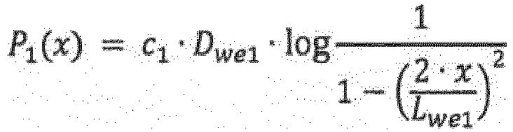

le coefficient logarithmique C2 des deuxièmes rouleaux coniques (8) étant différent du coefficient logarithmique de référence C0 de 0,00045, et le coefficient logarithmique C1 des premiers rouleaux coniques (6) étant inférieur au coefficient logarithmique de référence C0 et le coefficient logarithmique C2 des deuxièmes rouleaux coniques (8) étant supérieur au coefficient logarithmique de référence C0. - Ensemble palier à roulement (1) selon la revendication précédente, dans lequel le coefficient logarithmique C1 des premiers rouleaux coniques (6) est compris entre 0,0001 et 0,0004, de préférence entre 0,00025 et 0,00035 et de manière particulièrement préférée est de sensiblement 0,0003.
- Ensemble palier à roulement (1) selon l'une des revendications précédentes, dans lequel le coefficient logarithmique C2 des deuxièmes rouleaux coniques (8) est compris entre 0,0005 et 0,0009, de préférence entre 0,0006 et 0,0008 et de manière particulièrement préférée est de sensiblement 0,0007.
- Ensemble palier à roulement (1) selon l'une des revendications précédentes, dans lequel les premiers et deuxièmes rouleaux coniques (6, 8) ne diffèrent les uns des autres que de par leur profilage de rouleau et présentent en particulier la même longueur effective Lwe1,2 et le même diamètre maximal Dwe1,2.
- Ensemble palier à roulement (1) selon l'une des revendications précédentes, dans lequel le premier et le deuxième palier à rouleaux coniques (5, 7) sont positionnés l'un par rapport à l'autre de telle sorte que les premiers et deuxièmes rouleaux coniques (6, 8) sont disposés en forme de x dans une coupe longitudinale radiale parallèle à l'axe de rotation (4) à travers l'ensemble palier à roulement (1).
- Ensemble palier à roulement (1) selon l'une des revendications précédentes, dans lequel le premier et le deuxième palier à rouleaux coniques (5, 7) sont orientés l'un par rapport à l'autre de telle sorte que les premiers et deuxièmes rouleaux coniques (6, 8) sont disposés en forme de o dans une coupe longitudinale parallèle à l'axe de rotation (4) à travers l'ensemble palier à roulement (1) .
- Éolienne (10) comprenant un moyeu de rotor (9) auquel est fixée au moins une pale de rotor (12), et un générateur, lequel est conçu pour la conversion d'énergie cinétique en énergie électrique, dans laquelle un rotor du générateur est relié de manière solidaire en rotation au moyeu de rotor (9) par le biais d'un arbre de rotor de l'éolienne (10), caractérisée en ce que le moyeu de rotor (9) et/ou l'arbre de rotor sont montés au moyen de l'ensemble palier à roulement (1) selon l'une des revendications précédentes.
- Éolienne (10) selon la revendication 7, dans laquelle la bague intérieure (3) ou la bague extérieure (2) est reliée de manière solidaire en rotation à l'arbre de rotor.
- Éolienne (10) selon l'une des revendications 7 ou 8, dans laquelle le premier palier à rouleaux coniques (5) est disposé sur un côté de l'ensemble palier à roulement (1) tourné vers le moyeu de rotor (9) et le deuxième palier à rouleaux coniques (6) est disposé sur un côté de l'ensemble palier à roulement (1) tourné vers le générateur.
Applications Claiming Priority (2)
| Application Number | Priority Date | Filing Date | Title |
|---|---|---|---|
| DE102017106962.3A DE102017106962A1 (de) | 2017-03-31 | 2017-03-31 | Wälzlageranordnung und Windkraftanlage |
| PCT/EP2018/057487 WO2018177946A1 (fr) | 2017-03-31 | 2018-03-23 | Ensemble palier à roulement et éolienne |
Publications (2)
| Publication Number | Publication Date |
|---|---|
| EP3601819A1 EP3601819A1 (fr) | 2020-02-05 |
| EP3601819B1 true EP3601819B1 (fr) | 2020-11-25 |
Family
ID=61899214
Family Applications (1)
| Application Number | Title | Priority Date | Filing Date |
|---|---|---|---|
| EP18715560.1A Active EP3601819B1 (fr) | 2017-03-31 | 2018-03-23 | Ensemble palier à roulement et éolienne |
Country Status (5)
| Country | Link |
|---|---|
| EP (1) | EP3601819B1 (fr) |
| CN (1) | CN110520641B (fr) |
| DE (1) | DE102017106962A1 (fr) |
| DK (1) | DK3601819T3 (fr) |
| WO (1) | WO2018177946A1 (fr) |
Families Citing this family (6)
| Publication number | Priority date | Publication date | Assignee | Title |
|---|---|---|---|---|
| DE102018213951A1 (de) * | 2018-08-17 | 2020-02-20 | Thyssenkrupp Ag | Wälzkörper mit asymmetrischer Rollenprofilierung, Wälzlager, Windkraftanlage und Verfahren zur geometrischen Dimensionierung von Wälzkörpern |
| DE102018218275A1 (de) * | 2018-10-25 | 2020-04-30 | Thyssenkrupp Ag | Wälzlageranordnung und Windkraftanlage |
| CN111878507B (zh) * | 2020-08-27 | 2025-07-15 | 明阳智慧能源集团股份公司 | 风电机组非对称双列圆锥滚子主轴承及其设计方法 |
| CN112253619A (zh) * | 2020-11-25 | 2021-01-22 | 瓦房店轴承集团国家轴承工程技术研究中心有限公司 | 风电主轴用大锥角双列圆锥滚子轴承 |
| DE102022200534A1 (de) | 2022-01-18 | 2023-08-03 | Thyssenkrupp Ag | Belastungsoptimierte Großwälzlageranordnung |
| WO2025020118A1 (fr) * | 2023-07-26 | 2025-01-30 | The Timken Company | Agencement de palier pour arbre principal d'éolienne |
Family Cites Families (13)
| Publication number | Priority date | Publication date | Assignee | Title |
|---|---|---|---|---|
| DE4440260A1 (de) * | 1994-11-11 | 1996-05-15 | Kugelfischer G Schaefer & Co | Kegelrollenlager |
| JP2005147331A (ja) * | 2003-11-18 | 2005-06-09 | Ntn Corp | 複列転がり軸受 |
| JP2006177446A (ja) * | 2004-12-22 | 2006-07-06 | Ntn Corp | 調心輪付き円錐ころ軸受 |
| WO2007095953A1 (fr) * | 2006-02-24 | 2007-08-30 | Vestas Wind Systems A/S | Boite a engrenages pour turbine eolienne, roulement et procede de fabrication d'un roulement |
| BE1017166A3 (fr) * | 2006-06-13 | 2008-03-04 | Hansen Transmissions Int | |
| DE102007049087A1 (de) | 2007-10-12 | 2009-04-23 | Rothe Erde Gmbh | Radial- und axial belastbares Wälzlager |
| CN201651047U (zh) * | 2010-01-12 | 2010-11-24 | 浙江进发轴承有限公司 | 一种改进的双列圆锥滚子轴承 |
| DE102010054948A1 (de) * | 2010-12-17 | 2012-06-21 | Schaeffler Technologies Gmbh & Co. Kg | Lageranordnung |
| CN102135134B (zh) * | 2011-03-25 | 2013-06-19 | 浙江兆丰机电股份有限公司 | 汽车轮毂轴承单元 |
| JP5982782B2 (ja) * | 2011-10-28 | 2016-08-31 | 日本精工株式会社 | 風力発電設備用転がり軸受 |
| DE102013201326A1 (de) * | 2013-01-28 | 2014-07-31 | Aktiebolaget Skf | Wälzlager mit verbesserten Lasteigenschaften |
| DE202014010876U1 (de) | 2014-04-04 | 2017-04-07 | Thyssenkrupp Ag | Wälzlageranordnung und Windkraftanlage |
| DE102014106558A1 (de) | 2014-05-09 | 2015-11-12 | Thyssenkrupp Ag | Lageranordnung und Kegelrollenlager |
-
2017
- 2017-03-31 DE DE102017106962.3A patent/DE102017106962A1/de not_active Ceased
-
2018
- 2018-03-23 EP EP18715560.1A patent/EP3601819B1/fr active Active
- 2018-03-23 CN CN201880020835.XA patent/CN110520641B/zh active Active
- 2018-03-23 WO PCT/EP2018/057487 patent/WO2018177946A1/fr not_active Ceased
- 2018-03-23 DK DK18715560.1T patent/DK3601819T3/da active
Non-Patent Citations (1)
| Title |
|---|
| None * |
Also Published As
| Publication number | Publication date |
|---|---|
| CN110520641A (zh) | 2019-11-29 |
| DE102017106962A1 (de) | 2018-10-04 |
| DK3601819T3 (da) | 2021-03-01 |
| WO2018177946A1 (fr) | 2018-10-04 |
| CN110520641B (zh) | 2021-07-13 |
| EP3601819A1 (fr) | 2020-02-05 |
Similar Documents
| Publication | Publication Date | Title |
|---|---|---|
| EP3601819B1 (fr) | Ensemble palier à roulement et éolienne | |
| EP2715162B2 (fr) | Couronne d'orientation | |
| EP2079942B1 (fr) | Ensemble de palier pour le montage à rotation d'un pignon satellite sur un porte-satellites | |
| EP2627921B1 (fr) | Bloc en tant qu'ensemble palier pour le montage rotatif de parties de machine et d'installation | |
| WO2013117980A1 (fr) | Ensemble destiné à supporter des pièces d'une installation de production d'énergie pouvant tourner les unes par rapport aux autres | |
| DE102015218228A1 (de) | Rotorwellenanordnung für Windrad | |
| EP2947339A1 (fr) | Grand palier, en particulier palier principal pour une éolienne, et éolienne dotée d'un tel grand palier | |
| WO2010037370A1 (fr) | Liaison rotative, notamment palier à roulement doté de trois bagues de roulement concentriques et rangées de corps roulants à rouleaux et à billes croisées, à quatre points de contact pour une éolienne | |
| EP3721104B1 (fr) | Agencement de paliers a roulement | |
| DE102008038534A1 (de) | Wälzlageranordnung und damit ausgerüstete Windkraftanlage | |
| EP2683941B1 (fr) | Transmission planétaire pour éolienne | |
| WO2015150159A1 (fr) | Ensemble palier à roulement et éolienne | |
| EP1519058B1 (fr) | Éolienne comprenant un palier pour le rotor | |
| EP4337872B1 (fr) | Nacelle pour éolienne | |
| WO2017025343A1 (fr) | Ensemble de paliers à roulement et palier de pale pour éolienne | |
| DE102012221255A1 (de) | Lagereinheit für eine Windkraftmaschine | |
| EP3870869B1 (fr) | Ensemble de paliers à roulement et éolienne | |
| EP3434917A1 (fr) | Dispositif palier destiné au logement d'un arbre de transmission | |
| WO2009059585A2 (fr) | Montage d'une roue planétaire pour optimiser la répartition des charges | |
| DE102014219702A1 (de) | Laufbahnstruktur für ein Wälzlager und Verfahren | |
| EP3230622A1 (fr) | Arbre de roue planétaire monté de façon articulée | |
| DE102013216841A1 (de) | Rotorblattlagerung | |
| WO2024011273A1 (fr) | Agencement de palier lisse, nacelle équipée de l'agencement de palier lisse pour une éolienne, et éolienne | |
| EP3721103B1 (fr) | Assemblage de paliers roulants | |
| EP3421789B1 (fr) | Palier à roulement pour chaîne cinématique de l'éolienne |
Legal Events
| Date | Code | Title | Description |
|---|---|---|---|
| STAA | Information on the status of an ep patent application or granted ep patent |
Free format text: STATUS: UNKNOWN |
|
| STAA | Information on the status of an ep patent application or granted ep patent |
Free format text: STATUS: THE INTERNATIONAL PUBLICATION HAS BEEN MADE |
|
| PUAI | Public reference made under article 153(3) epc to a published international application that has entered the european phase |
Free format text: ORIGINAL CODE: 0009012 |
|
| STAA | Information on the status of an ep patent application or granted ep patent |
Free format text: STATUS: REQUEST FOR EXAMINATION WAS MADE |
|
| 17P | Request for examination filed |
Effective date: 20191031 |
|
| AK | Designated contracting states |
Kind code of ref document: A1 Designated state(s): AL AT BE BG CH CY CZ DE DK EE ES FI FR GB GR HR HU IE IS IT LI LT LU LV MC MK MT NL NO PL PT RO RS SE SI SK SM TR |
|
| AX | Request for extension of the european patent |
Extension state: BA ME |
|
| RAP1 | Party data changed (applicant data changed or rights of an application transferred) |
Owner name: THYSSENKRUPP AG Owner name: THYSSENKRUPP ROTHE ERDE GERMANY GMBH |
|
| RAP1 | Party data changed (applicant data changed or rights of an application transferred) |
Owner name: THYSSENKRUPP ROTHE ERDE GERMANY GMBH Owner name: THYSSENKRUPP AG |
|
| DAV | Request for validation of the european patent (deleted) | ||
| DAX | Request for extension of the european patent (deleted) | ||
| GRAP | Despatch of communication of intention to grant a patent |
Free format text: ORIGINAL CODE: EPIDOSNIGR1 |
|
| STAA | Information on the status of an ep patent application or granted ep patent |
Free format text: STATUS: GRANT OF PATENT IS INTENDED |
|
| INTG | Intention to grant announced |
Effective date: 20200831 |
|
| GRAS | Grant fee paid |
Free format text: ORIGINAL CODE: EPIDOSNIGR3 |
|
| GRAA | (expected) grant |
Free format text: ORIGINAL CODE: 0009210 |
|
| STAA | Information on the status of an ep patent application or granted ep patent |
Free format text: STATUS: THE PATENT HAS BEEN GRANTED |
|
| AK | Designated contracting states |
Kind code of ref document: B1 Designated state(s): AL AT BE BG CH CY CZ DE DK EE ES FI FR GB GR HR HU IE IS IT LI LT LU LV MC MK MT NL NO PL PT RO RS SE SI SK SM TR |
|
| REG | Reference to a national code |
Ref country code: GB Ref legal event code: FG4D Free format text: NOT ENGLISH |
|
| REG | Reference to a national code |
Ref country code: CH Ref legal event code: EP |
|
| REG | Reference to a national code |
Ref country code: AT Ref legal event code: REF Ref document number: 1338659 Country of ref document: AT Kind code of ref document: T Effective date: 20201215 |
|
| REG | Reference to a national code |
Ref country code: DE Ref legal event code: R096 Ref document number: 502018003131 Country of ref document: DE |
|
| REG | Reference to a national code |
Ref country code: IE Ref legal event code: FG4D Free format text: LANGUAGE OF EP DOCUMENT: GERMAN |
|
| REG | Reference to a national code |
Ref country code: DK Ref legal event code: T3 Effective date: 20210225 |
|
| REG | Reference to a national code |
Ref country code: NL Ref legal event code: MP Effective date: 20201125 |
|
| PG25 | Lapsed in a contracting state [announced via postgrant information from national office to epo] |
Ref country code: GR Free format text: LAPSE BECAUSE OF FAILURE TO SUBMIT A TRANSLATION OF THE DESCRIPTION OR TO PAY THE FEE WITHIN THE PRESCRIBED TIME-LIMIT Effective date: 20210226 Ref country code: NO Free format text: LAPSE BECAUSE OF FAILURE TO SUBMIT A TRANSLATION OF THE DESCRIPTION OR TO PAY THE FEE WITHIN THE PRESCRIBED TIME-LIMIT Effective date: 20210225 Ref country code: FI Free format text: LAPSE BECAUSE OF FAILURE TO SUBMIT A TRANSLATION OF THE DESCRIPTION OR TO PAY THE FEE WITHIN THE PRESCRIBED TIME-LIMIT Effective date: 20201125 Ref country code: RS Free format text: LAPSE BECAUSE OF FAILURE TO SUBMIT A TRANSLATION OF THE DESCRIPTION OR TO PAY THE FEE WITHIN THE PRESCRIBED TIME-LIMIT Effective date: 20201125 Ref country code: PT Free format text: LAPSE BECAUSE OF FAILURE TO SUBMIT A TRANSLATION OF THE DESCRIPTION OR TO PAY THE FEE WITHIN THE PRESCRIBED TIME-LIMIT Effective date: 20210325 |
|
| PG25 | Lapsed in a contracting state [announced via postgrant information from national office to epo] |
Ref country code: SE Free format text: LAPSE BECAUSE OF FAILURE TO SUBMIT A TRANSLATION OF THE DESCRIPTION OR TO PAY THE FEE WITHIN THE PRESCRIBED TIME-LIMIT Effective date: 20201125 Ref country code: PL Free format text: LAPSE BECAUSE OF FAILURE TO SUBMIT A TRANSLATION OF THE DESCRIPTION OR TO PAY THE FEE WITHIN THE PRESCRIBED TIME-LIMIT Effective date: 20201125 Ref country code: LV Free format text: LAPSE BECAUSE OF FAILURE TO SUBMIT A TRANSLATION OF THE DESCRIPTION OR TO PAY THE FEE WITHIN THE PRESCRIBED TIME-LIMIT Effective date: 20201125 Ref country code: IS Free format text: LAPSE BECAUSE OF FAILURE TO SUBMIT A TRANSLATION OF THE DESCRIPTION OR TO PAY THE FEE WITHIN THE PRESCRIBED TIME-LIMIT Effective date: 20210325 Ref country code: BG Free format text: LAPSE BECAUSE OF FAILURE TO SUBMIT A TRANSLATION OF THE DESCRIPTION OR TO PAY THE FEE WITHIN THE PRESCRIBED TIME-LIMIT Effective date: 20210225 |
|
| REG | Reference to a national code |
Ref country code: LT Ref legal event code: MG9D |
|
| PG25 | Lapsed in a contracting state [announced via postgrant information from national office to epo] |
Ref country code: HR Free format text: LAPSE BECAUSE OF FAILURE TO SUBMIT A TRANSLATION OF THE DESCRIPTION OR TO PAY THE FEE WITHIN THE PRESCRIBED TIME-LIMIT Effective date: 20201125 |
|
| PG25 | Lapsed in a contracting state [announced via postgrant information from national office to epo] |
Ref country code: RO Free format text: LAPSE BECAUSE OF FAILURE TO SUBMIT A TRANSLATION OF THE DESCRIPTION OR TO PAY THE FEE WITHIN THE PRESCRIBED TIME-LIMIT Effective date: 20201125 Ref country code: LT Free format text: LAPSE BECAUSE OF FAILURE TO SUBMIT A TRANSLATION OF THE DESCRIPTION OR TO PAY THE FEE WITHIN THE PRESCRIBED TIME-LIMIT Effective date: 20201125 Ref country code: CZ Free format text: LAPSE BECAUSE OF FAILURE TO SUBMIT A TRANSLATION OF THE DESCRIPTION OR TO PAY THE FEE WITHIN THE PRESCRIBED TIME-LIMIT Effective date: 20201125 Ref country code: EE Free format text: LAPSE BECAUSE OF FAILURE TO SUBMIT A TRANSLATION OF THE DESCRIPTION OR TO PAY THE FEE WITHIN THE PRESCRIBED TIME-LIMIT Effective date: 20201125 Ref country code: SM Free format text: LAPSE BECAUSE OF FAILURE TO SUBMIT A TRANSLATION OF THE DESCRIPTION OR TO PAY THE FEE WITHIN THE PRESCRIBED TIME-LIMIT Effective date: 20201125 Ref country code: SK Free format text: LAPSE BECAUSE OF FAILURE TO SUBMIT A TRANSLATION OF THE DESCRIPTION OR TO PAY THE FEE WITHIN THE PRESCRIBED TIME-LIMIT Effective date: 20201125 |
|
| REG | Reference to a national code |
Ref country code: DE Ref legal event code: R097 Ref document number: 502018003131 Country of ref document: DE |
|
| PLBE | No opposition filed within time limit |
Free format text: ORIGINAL CODE: 0009261 |
|
| STAA | Information on the status of an ep patent application or granted ep patent |
Free format text: STATUS: NO OPPOSITION FILED WITHIN TIME LIMIT |
|
| PG25 | Lapsed in a contracting state [announced via postgrant information from national office to epo] |
Ref country code: NL Free format text: LAPSE BECAUSE OF FAILURE TO SUBMIT A TRANSLATION OF THE DESCRIPTION OR TO PAY THE FEE WITHIN THE PRESCRIBED TIME-LIMIT Effective date: 20201125 Ref country code: AL Free format text: LAPSE BECAUSE OF FAILURE TO SUBMIT A TRANSLATION OF THE DESCRIPTION OR TO PAY THE FEE WITHIN THE PRESCRIBED TIME-LIMIT Effective date: 20201125 Ref country code: IT Free format text: LAPSE BECAUSE OF FAILURE TO SUBMIT A TRANSLATION OF THE DESCRIPTION OR TO PAY THE FEE WITHIN THE PRESCRIBED TIME-LIMIT Effective date: 20201125 Ref country code: MC Free format text: LAPSE BECAUSE OF FAILURE TO SUBMIT A TRANSLATION OF THE DESCRIPTION OR TO PAY THE FEE WITHIN THE PRESCRIBED TIME-LIMIT Effective date: 20201125 |
|
| REG | Reference to a national code |
Ref country code: CH Ref legal event code: PL |
|
| 26N | No opposition filed |
Effective date: 20210826 |
|
| PG25 | Lapsed in a contracting state [announced via postgrant information from national office to epo] |
Ref country code: SI Free format text: LAPSE BECAUSE OF FAILURE TO SUBMIT A TRANSLATION OF THE DESCRIPTION OR TO PAY THE FEE WITHIN THE PRESCRIBED TIME-LIMIT Effective date: 20201125 |
|
| REG | Reference to a national code |
Ref country code: BE Ref legal event code: MM Effective date: 20210331 |
|
| PG25 | Lapsed in a contracting state [announced via postgrant information from national office to epo] |
Ref country code: ES Free format text: LAPSE BECAUSE OF FAILURE TO SUBMIT A TRANSLATION OF THE DESCRIPTION OR TO PAY THE FEE WITHIN THE PRESCRIBED TIME-LIMIT Effective date: 20201125 Ref country code: LI Free format text: LAPSE BECAUSE OF NON-PAYMENT OF DUE FEES Effective date: 20210331 Ref country code: LU Free format text: LAPSE BECAUSE OF NON-PAYMENT OF DUE FEES Effective date: 20210323 Ref country code: IE Free format text: LAPSE BECAUSE OF NON-PAYMENT OF DUE FEES Effective date: 20210323 Ref country code: CH Free format text: LAPSE BECAUSE OF NON-PAYMENT OF DUE FEES Effective date: 20210331 |
|
| PG25 | Lapsed in a contracting state [announced via postgrant information from national office to epo] |
Ref country code: IS Free format text: LAPSE BECAUSE OF FAILURE TO SUBMIT A TRANSLATION OF THE DESCRIPTION OR TO PAY THE FEE WITHIN THE PRESCRIBED TIME-LIMIT Effective date: 20210325 |
|
| PG25 | Lapsed in a contracting state [announced via postgrant information from national office to epo] |
Ref country code: BE Free format text: LAPSE BECAUSE OF NON-PAYMENT OF DUE FEES Effective date: 20210331 |
|
| PG25 | Lapsed in a contracting state [announced via postgrant information from national office to epo] |
Ref country code: CY Free format text: LAPSE BECAUSE OF FAILURE TO SUBMIT A TRANSLATION OF THE DESCRIPTION OR TO PAY THE FEE WITHIN THE PRESCRIBED TIME-LIMIT Effective date: 20201125 |
|
| PG25 | Lapsed in a contracting state [announced via postgrant information from national office to epo] |
Ref country code: HU Free format text: LAPSE BECAUSE OF FAILURE TO SUBMIT A TRANSLATION OF THE DESCRIPTION OR TO PAY THE FEE WITHIN THE PRESCRIBED TIME-LIMIT; INVALID AB INITIO Effective date: 20180323 |
|
| PG25 | Lapsed in a contracting state [announced via postgrant information from national office to epo] |
Ref country code: MK Free format text: LAPSE BECAUSE OF FAILURE TO SUBMIT A TRANSLATION OF THE DESCRIPTION OR TO PAY THE FEE WITHIN THE PRESCRIBED TIME-LIMIT Effective date: 20201125 |
|
| REG | Reference to a national code |
Ref country code: AT Ref legal event code: MM01 Ref document number: 1338659 Country of ref document: AT Kind code of ref document: T Effective date: 20230323 |
|
| PG25 | Lapsed in a contracting state [announced via postgrant information from national office to epo] |
Ref country code: TR Free format text: LAPSE BECAUSE OF FAILURE TO SUBMIT A TRANSLATION OF THE DESCRIPTION OR TO PAY THE FEE WITHIN THE PRESCRIBED TIME-LIMIT Effective date: 20201125 |
|
| PG25 | Lapsed in a contracting state [announced via postgrant information from national office to epo] |
Ref country code: AT Free format text: LAPSE BECAUSE OF NON-PAYMENT OF DUE FEES Effective date: 20230323 |
|
| PG25 | Lapsed in a contracting state [announced via postgrant information from national office to epo] |
Ref country code: AT Free format text: LAPSE BECAUSE OF NON-PAYMENT OF DUE FEES Effective date: 20230323 |
|
| PG25 | Lapsed in a contracting state [announced via postgrant information from national office to epo] |
Ref country code: MT Free format text: LAPSE BECAUSE OF FAILURE TO SUBMIT A TRANSLATION OF THE DESCRIPTION OR TO PAY THE FEE WITHIN THE PRESCRIBED TIME-LIMIT Effective date: 20201125 |
|
| PGFP | Annual fee paid to national office [announced via postgrant information from national office to epo] |
Ref country code: GB Payment date: 20260324 Year of fee payment: 9 |
|
| PGFP | Annual fee paid to national office [announced via postgrant information from national office to epo] |
Ref country code: DK Payment date: 20260324 Year of fee payment: 9 Ref country code: DE Payment date: 20260319 Year of fee payment: 9 |
|
| PGFP | Annual fee paid to national office [announced via postgrant information from national office to epo] |
Ref country code: AT Payment date: 20260410 Year of fee payment: 5 |
|
| PGFP | Annual fee paid to national office [announced via postgrant information from national office to epo] |
Ref country code: FR Payment date: 20260320 Year of fee payment: 9 |