EP3603376A1 - Machine de récolte doté d'une tête de récolte et d'une roue d'appui - Google Patents
Machine de récolte doté d'une tête de récolte et d'une roue d'appui Download PDFInfo
- Publication number
- EP3603376A1 EP3603376A1 EP19189301.5A EP19189301A EP3603376A1 EP 3603376 A1 EP3603376 A1 EP 3603376A1 EP 19189301 A EP19189301 A EP 19189301A EP 3603376 A1 EP3603376 A1 EP 3603376A1
- Authority
- EP
- European Patent Office
- Prior art keywords
- harvesting
- support wheel
- harvesting machine
- attached
- ground
- Prior art date
- Legal status (The legal status is an assumption and is not a legal conclusion. Google has not performed a legal analysis and makes no representation as to the accuracy of the status listed.)
- Granted
Links
Images
Classifications
-
- A—HUMAN NECESSITIES
- A01—AGRICULTURE; FORESTRY; ANIMAL HUSBANDRY; HUNTING; TRAPPING; FISHING
- A01D—HARVESTING; MOWING
- A01D41/00—Combines, i.e. harvesters or mowers combined with threshing devices
- A01D41/12—Details of combines
- A01D41/14—Mowing tables
-
- A—HUMAN NECESSITIES
- A01—AGRICULTURE; FORESTRY; ANIMAL HUSBANDRY; HUNTING; TRAPPING; FISHING
- A01D—HARVESTING; MOWING
- A01D75/00—Accessories for harvesters or mowers
- A01D75/002—Carriers for the transport of harvesters or mowers
-
- B—PERFORMING OPERATIONS; TRANSPORTING
- B62—LAND VEHICLES FOR TRAVELLING OTHERWISE THAN ON RAILS
- B62D—MOTOR VEHICLES; TRAILERS
- B62D37/00—Stabilising vehicle bodies without controlling suspension arrangements
- B62D37/04—Stabilising vehicle bodies without controlling suspension arrangements by means of movable masses
-
- B—PERFORMING OPERATIONS; TRANSPORTING
- B62—LAND VEHICLES FOR TRAVELLING OTHERWISE THAN ON RAILS
- B62D—MOTOR VEHICLES; TRAILERS
- B62D49/00—Tractors
- B62D49/06—Tractors adapted for multi-purpose use
- B62D49/0621—Tractors adapted for multi-purpose use comprising traction increasing arrangements, e.g. all-wheel traction devices, multiple-axle traction arrangements, auxiliary traction increasing devices
- B62D49/0628—Tractors adapted for multi-purpose use comprising traction increasing arrangements, e.g. all-wheel traction devices, multiple-axle traction arrangements, auxiliary traction increasing devices using detachable weights
-
- A—HUMAN NECESSITIES
- A01—AGRICULTURE; FORESTRY; ANIMAL HUSBANDRY; HUNTING; TRAPPING; FISHING
- A01B—SOIL WORKING IN AGRICULTURE OR FORESTRY; PARTS, DETAILS, OR ACCESSORIES OF AGRICULTURAL MACHINES OR IMPLEMENTS, IN GENERAL
- A01B63/00—Lifting or adjusting devices or arrangements for agricultural machines or implements
- A01B63/02—Lifting or adjusting devices or arrangements for agricultural machines or implements for implements mounted on tractors
- A01B63/10—Lifting or adjusting devices or arrangements for agricultural machines or implements for implements mounted on tractors operated by hydraulic or pneumatic means
- A01B63/11—Lifting or adjusting devices or arrangements for agricultural machines or implements for implements mounted on tractors operated by hydraulic or pneumatic means for controlling weight transfer between implements and tractor wheels
Definitions
- the invention relates to a self-propelled harvesting machine with a chassis supported on the ground by front and rear wheels and / or caterpillar drives, a feed conveyor to which a harvesting attachment is attached, and at least one support wheel which can be attached in front of the front wheels or caterpillar drives and brought into ground engagement.
- harvesting attachments are used to harvest and bring in crops. Due to recent increases in the performance of the harvesting machines, ever wider harvesting headers are used which have a relatively large mass. While combine harvesters for harvesters are usually rigid and separated from the combine harvester for road transport and placed on a trolley, corn harvesters for combine harvesters and corn headers for forage harvesters are usually designed to be foldable. However, there are also foldable cutting units for combine harvesters. For road transport, outer side parts of the harvesting attachments are pivoted into a transport position, usually upwards or inwards. They remain attached to the front of the harvester during road transport. The legally permissible weight load on the front wheels of the harvesting machine is problematic with the increasingly wide and heavy harvesting headers.
- the additional wheel is attached to a separate auxiliary undercarriage, which can be positioned under and fixed to the header.
- the auxiliary chassis reduces the axle load of the front wheels of the harvester when driving on the road and to a certain extent also increases the axle load of the rear wheels compared to the situation without an auxiliary chassis.
- the auxiliary undercarriage is removed and a higher axle load of the front wheels is obtained compared to road travel, while the axle load of the rear wheels is reduced.
- the system consisting of the load on the support wheel, front axle load and rear axle load is influenced in the prior art with the aid of rear ballast in such a way that the legal requirements in particular with regard to the front axle load. Often, all these values are close to the permissible maximum value, so that additional ballast material, so that the harvester can continue to be steered without problems to compensate for the reduced rear axle load after removal of the support wheel, cannot be carried. In addition, carrying ballast material would make no sense from an ecological point of view and should be kept to a minimum.
- ballast weights that can be shifted by actuators, which are automatically shifted, for example, based on the axle load of the vehicle ( DE 199 28 471 A1 ) as well as means for changing the axle load by moving a chassis of the harvesting machine based on the weight of a header or a recognized road driving mode ( EP 1 488 676 A1 ), but require relatively complex sensors to detect the axle load or the weight of the header or, in the case of activation based on the road mode, are susceptible to incorrect operation.
- the object on which the invention is based is to be seen in simple means to enable an adequate loading of the rear axle of a self-propelled harvesting machine with a harvesting attachment which can be supported by a support wheel during road travel and harvesting operation.
- a self-propelled harvester which can be, for example, a combine harvester, a forage harvester or a cotton picker, comprises a chassis that is supported on the ground by front and rear wheels. Instead of the front one Wheels or the rear wheels, or both, can also kick caterpillars.
- a feed conveyor is provided on the front of the chassis and a harvesting attachment is usually attached to it in a removable manner.
- a support wheel is attached in the forward direction in front of the front wheels (or caterpillar tracks) of the harvesting machine, which can be brought into ground contact.
- An electronic control device can be acted upon with a signal with regard to the ground engagement state of the support wheel and is set up to control an actuator for adjusting the position of a ballast weight depending on the signal.
- the ballast weight influences the load on the jockey wheel, on the front axle and on the rear axle and is moved in such a way that in both ground engagement states of the jockey wheel (active and inactive) there is a sensible load on the front wheels or caterpillar drives, the rear wheels or caterpillar drives and possibly of the jockey wheel.
- a support wheel can be brought into ground engagement or not by e.g. can be moved by an externally powered drive or by hand between an active ground engagement state supporting the header and an inactive ground engagement state in which it is raised and spaced from the ground or removed from the header or the harvesting machine or its feed conveyor.
- a suitable arrangement detects whether the support wheel is in the active or inactive ground engagement state and sends a corresponding signal to an electronic control device. Based on the signal, the control device commands an actuator which serves to adjust the position of a ballast weight, the position of which, among other things. affects the axle load of the rear wheels or crawler tracks.
- the support wheel can be attached to the header and / or the feed conveyor and / or the harvesting machine itself, for example on its front axle. If it is attached to the header, it is preferably attached to an auxiliary chassis which is attached to the header before a road trip and is removed again before the start of harvesting. But it would also be conceivable to keep the jockey wheel permanently on the header or to be attached to the feed conveyor and / or the harvesting machine and to be lifted when not in use by hand or by a power-operated drive, as mentioned above.
- the signal regarding the ground engagement state of the support wheel can be provided by an arrangement for recognizing the attachment status of the auxiliary landing gear.
- an arrangement for recognizing the attachment status of the auxiliary landing gear can include, for example, a sensor (e.g. switch) on the header which interacts with the auxiliary chassis.
- a sensor e.g. switch
- Another possibility is to provide a plug connection that automatically closes when the auxiliary undercarriage is mounted between the header and the auxiliary undercarriage with a contact that closes when the auxiliary undercarriage is attached.
- This contact (or the sensor) can also be used to control an actuator for height control of the header in order to adapt the ground pressure of the header to the auxiliary chassis attached.
- control device is programmed to instruct the actuator to put the ballast weight in a first position when the jockey wheel is in contact with the ground and to move the ballast weight in a second position when the jockey wheel is not in contact with the ground, the ballast weight in the first position placing less load on the rear wheels or caterpillar drives than in the second position.
- the ballast weight can be displaceable between the first position and the second position along the forward direction of the harvesting machine and / or can be pivoted about an axis running transverse to the forward direction.
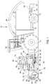
- FIG. 1 One in the Figure 1 shown self-propelled agricultural harvester 10 in style a forage harvester is built on a chassis 12 which is carried by front and rear wheels 14 and 16.
- the front wheels 14 serve as main drive wheels, while the rear wheels 16 are steerable.
- the harvesting machine 10 is operated from a driver's cab 18, from which a header 20 can be seen.
- Good picked up from the ground by means of a header 20, e.g. B. corn, sunflowers or sorghum, is fed in the harvesting operation via a feed conveyor 30 to a chopper drum (not shown) inside the harvester 10, which chops it into small pieces and gives it up to a conveyor device (also not shown).
- a shredding device (not shown) can be arranged between the chopper drum and the conveyor device.
- the invention is shown here on a forage harvester, it can also be used on combine harvesters with associated harvesting attachments, such as cutters or corn pickers.
- directional information as before, behind, to the side and above, relates to the forward direction of the harvesting machine 10 and the header 20, which are shown in FIG Figure 1 runs to the left.
- the harvesting header 20 which is fastened in the forward direction on the front of the harvesting machine 10 to the housing of the feed conveyor 30, is used to receive the harvested crop.
- the harvesting attachment 20 is a corn header known per se, which comprises a central part 38 and two side parts 40 arranged to the left and right of the central part 38 (with respect to the forward direction of the harvesting machine 10).
- the side parts 40 are pivotally attached to the middle part 38 for road transport and can be pivoted down hydraulically for harvesting by hydraulic cylinders (not shown), so that they run parallel to the middle part 38 during harvesting operation. Then they can be swung up again.
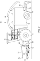
- the Figure 1 shows the side parts 40 in the pivoted-up state and the Figure 2 in the lowered state for harvesting.
- the harvesting attachment 20 is equipped in a manner known per se with straw dividers 36, the intake and mowing drums 32, divider tips 34, cover plates and conveying means in order to feed the harvested material to the chopper drum of the harvesting machine 10. During operation, the harvesting attachment 20 draws in the stalks of the crop in an upright position, cuts them off and guides them to the feed conveyor 30 and then to the chopper drum of the harvesting machine 10 to.
- the header 20 comprises a support frame which has a lower cross member 42 and an upper cross member 44.
- the lower cross member 42 extends at the bottom at the rear of the header 20 and comprises three segments, one of which is assigned to the central part 38 and each side part 40.
- Gearbox housings 46 are screwed onto the front of the lower crossmember 42 and are used to drive a feed and cutting drum 32.
- a drive shaft 48 for driving the feed and mowing drums 32 via gears arranged in the gear housings 46, which also serves to drive the further conveying means of the header 20 and is driven by an output shaft of the harvesting machine 10, extends laterally within the hollow lower crossmember 42.
- the upper cross member 44 extends laterally above the inlet of the feed conveyor 30 across its width. Hook-shaped support elements are provided on the upper side of the feed conveyor 30, which reach under the upper cross member 44 from the front and rear and serve to fasten the header 20 to the harvesting machine 10.
- the header 20 is coupled to an auxiliary undercarriage 50 for supporting the header 20 when driving on the road.
- the auxiliary undercarriage 50 comprises a frame 52 and a support wheel 54 which is mounted on a holder 58 such that it can rotate about an axis of rotation 56.
- the holder 58 is pivotably attached to a support element 62 about a horizontal pivot axis 60 oriented parallel to the axis of rotation 56, which in turn is articulated freely on the frame 52 about an approximately vertical axis.
- a hydraulic cylinder 64 Extending between the support element 62 and the holder 58 is a hydraulic cylinder 64, which is pivotably articulated at both fastening points 66 about axes extending parallel to the axis of rotation 56 and the pivot axis 60 and serves to specify the position of the support wheel 54 relative to the auxiliary chassis 50.
- the support wheel 54 could also be mounted at any other point on the auxiliary undercarriage 50, for example below the header 20.
- the frame 52 comprises a lower part 68, the rear end of which can be locked on the lower cross member 42, a vertical part 70 which extends approximately vertically upwards on the front of the lower part 68 and a front, approximately horizontal part which extends from the upper end of the vertical part 70 extends forward and to which the support element 62 is articulated.
- a strut 74 attached to the cross member 44 connects the upper end of the vertical member 70 to the upper cross member 44.
- the support wheel 54 is thus trailed by the support member 62 on the frame 52 and takes part of the load of the header 20 (or its entire load and possibly a part of the load of the harvesting machine 10).
- the header 20 and the auxiliary undercarriage 50 are shown in a road driving position.
- the auxiliary undercarriage 50 can be separated from the header by releasing the locks between the lower part 68 and the lower cross member 42 and between the strut 74 and the upper cross member 44.
- the side parts 40 of the header 20 can then be pivoted downwards. This situation is in the Figure 2 shown.
- the side parts 40 are pivoted up again and the auxiliary undercarriage 50 is locked on the cross members 42, 44.
- a detailed description of a possible embodiment of the auxiliary landing gear can be found in the DE 10 2004 059 038 A1 and DE 10 2007 035 744 A1 , the disclosures of which are incorporated by reference into this document.
- the support wheel 54 relieves the load on the front wheels 14 of the harvesting machine 10, which facilitates compliance with the legal regulations relating to the axle load of the front wheels 14.
- the rear wheels 16 are removed with the auxiliary undercarriage 50 ( Figure 2 ) is relieved of the situation when the auxiliary suspension is attached, which means that it is difficult to steer in unfavorable operating conditions (e.g. braking).
- the rear axle is to be weighed down by ballast weights attached to the rear of the harvesting machine 10 during operation. This ballast weight required during harvesting also influences the distribution of the load on support wheel 54, front wheels 14 and rear wheels 16 when driving on the road. Since the road is increasingly exhausted due to the ever wider attachments, it is often not exhausted possible to carry additional ballast so that it remains steerable even during harvesting.
- an electronic control device 76 is connected in a signal-transmitting manner to an arrangement 78 for recognizing the attachment state of the auxiliary undercarriage 50.
- This arrangement 78 is attached to the front of the strut 74 and comprises a sensor which interacts, for example mechanically, capacitively or inductively, with the adjacent part of the frame of the auxiliary undercarriage 50.
- a contact of the electrical connection can be grounded, for example, by the auxiliary undercarriage 50, so that the arrangement 78 recognizes the attached auxiliary undercarriage 50 on the basis of this connection.
- the electronic control device 76 is also connected in a signal-transmitting manner to a valve device 86, which is used to control an actuator 80, which can be designed as a hydraulic cylinder and is used to shift a ballast weight 84 that can be displaced in a bearing 84 in the forward direction of the harvesting machine 10.
- the actuator 80 shifts the ballast weight 82 forward in the direction of travel in order to relieve the rear axle of the harvesting machine 10 ( Figure 1 ) and when the auxiliary undercarriage 50 is removed, the actuator 80 shifts the ballast weight 82 backwards against the direction of travel in order to load the rear axle of the harvesting machine 10 ( Figure 2 ). In this way it is achieved with simple means that the rear wheels 16 are subjected to a suitable load in both ground engagement states of the support wheel 54 in order to enable a steering movement in the usual operating situations.
- the actuator 80 could pivot the ballast weight 82 about the transverse axis, as in FIG DE 10 2008 043 698 A1 , the disclosure of which is incorporated by reference into the present documentation.
- ballast weight 82 It would also be conceivable to refine the described position control of the ballast weight 82 on the basis of the ground engagement state of the support wheel 54 (or alternatively) using sensors to measure the support loads of the front wheels 14 and rear wheels 16 and to control the ballast shift using these measured values. It would also be conceivable to control the ballast position based on the air pressure in the tires, i.e. With the help of the tire size and / or width and the measured air pressure in the tire, the ground pressure is determined and the position of the ballast weight 82 is readjusted when the air pressure changes. Of course, it would also be possible to control the ballast position manually using an operator interface without any queries and sensors. The actuation of the actuator 80 can be carried out in all of the example cases mentioned with the aim of maintaining a predetermined or permissible ground pressure, as is currently being discussed as a possible change in the legal requirements, which currently still relate to the axle load.
- the adjustable ballast weight 82 makes it easier to comply with the legal requirements than would be possible with an unadjustable ballast weight 82.
- the load distribution to the front and rear wheels 14, 16 is positively influenced solely by its position, without significantly increasing the total weight of the harvesting machine 10.
- Control of the axle loads by sensors or similar components is switched from static load distribution to a load distribution that automatically adapts to the circumstances.
Landscapes
- Engineering & Computer Science (AREA)
- Chemical & Material Sciences (AREA)
- Combustion & Propulsion (AREA)
- Transportation (AREA)
- Mechanical Engineering (AREA)
- Life Sciences & Earth Sciences (AREA)
- Environmental Sciences (AREA)
- Harvester Elements (AREA)
- Harvesting Machines For Specific Crops (AREA)
Applications Claiming Priority (1)
| Application Number | Priority Date | Filing Date | Title |
|---|---|---|---|
| DE102018212931.2A DE102018212931A1 (de) | 2018-08-02 | 2018-08-02 | Erntemaschine mit einem Erntevorsatz und einem Stützrad |
Publications (2)
| Publication Number | Publication Date |
|---|---|
| EP3603376A1 true EP3603376A1 (fr) | 2020-02-05 |
| EP3603376B1 EP3603376B1 (fr) | 2023-09-20 |
Family
ID=67514365
Family Applications (1)
| Application Number | Title | Priority Date | Filing Date |
|---|---|---|---|
| EP19189301.5A Active EP3603376B1 (fr) | 2018-08-02 | 2019-07-31 | Machine de récolte doté d'une tête de récolte et d'une roue d'appui |
Country Status (2)
| Country | Link |
|---|---|
| EP (1) | EP3603376B1 (fr) |
| DE (1) | DE102018212931A1 (fr) |
Cited By (2)
| Publication number | Priority date | Publication date | Assignee | Title |
|---|---|---|---|---|
| CN118765726A (zh) * | 2024-07-30 | 2024-10-15 | 江苏裕灌现代农业科技有限公司 | 一种双孢菇自动采摘装置及其自缓冲行走机构 |
| CN118790360A (zh) * | 2024-09-11 | 2024-10-18 | 龙门实验室 | 智能化农业机械收割车路辅助装置 |
Citations (14)
| Publication number | Priority date | Publication date | Assignee | Title |
|---|---|---|---|---|
| GB773685A (en) * | 1954-02-05 | 1957-05-01 | Harold Cecil John Jackson | Combine harvester |
| DE19918551A1 (de) | 1999-04-23 | 2000-10-26 | Deere & Co | Erntemaschine |
| DE19928471A1 (de) | 1999-06-22 | 2001-01-04 | Deere & Co | Arbeitsffahrzeug |
| EP1488676A1 (fr) | 2003-06-18 | 2004-12-22 | Deere & Company | Moissonneuse automotrice |
| EP1493599A2 (fr) | 2003-07-02 | 2005-01-05 | CLAAS Selbstfahrende Erntemaschinen GmbH | Installation de réglage de la pression de pneus |
| DE102004059038A1 (de) | 2004-12-07 | 2006-07-06 | Maschinenfabrik Kemper Gmbh & Co. Kg | Kombination aus einer Erntemaschine, einem Erntevorsatz und einem Wagen zur Abstützung des Erntevorsatzes |
| DE102007035744A1 (de) | 2007-07-31 | 2009-02-05 | Maschinenfabrik Kemper Gmbh & Co. Kg | Kombination aus einem Erntevorsatz und einem Wagen zur Abstützung des Erntevorsatzes und Verfahren zur Ankopplung des Wagens |
| DE102008056297A1 (de) * | 2008-11-07 | 2010-05-12 | Claas Selbstfahrende Erntemaschinen Gmbh | Landwirtschaftliche Erntemaschine |
| DE102008043698A1 (de) | 2008-11-13 | 2010-05-20 | Deere & Company, Moline | Ballastiervorrichtung und landwirtschaftliches Fahrzeug mit einer solchen |
| DE102010002506A1 (de) | 2010-03-02 | 2011-09-08 | Deere & Company | Erntemaschine mit einem Erntevorsatz und einem Stützrad |
| DE102011004028A1 (de) | 2011-02-14 | 2012-08-16 | Continental Automotive Gmbh | Verfahren und Verfahren zum Ermitteln der Beladung eines Kraftfahrzeugs und Kraftfahrzeug |
| WO2013025884A1 (fr) | 2011-08-17 | 2013-02-21 | Deere & Company | Gestion des pneus à base en v au niveau d'un parc de véhicules |
| DE102014209218A1 (de) | 2014-04-09 | 2015-10-15 | Maschinenfabrik Kemper Gmbh & Co. Kg | Kombination aus einem Erntevorsatz und einer für eine Straßenfahrt temporär an dem Erntevorsatz anbringbaren Vorrichtung |
| EP3162178A1 (fr) * | 2015-10-15 | 2017-05-03 | AGCO International GmbH | Contrepoids pour vehicule |
-
2018
- 2018-08-02 DE DE102018212931.2A patent/DE102018212931A1/de not_active Withdrawn
-
2019
- 2019-07-31 EP EP19189301.5A patent/EP3603376B1/fr active Active
Patent Citations (14)
| Publication number | Priority date | Publication date | Assignee | Title |
|---|---|---|---|---|
| GB773685A (en) * | 1954-02-05 | 1957-05-01 | Harold Cecil John Jackson | Combine harvester |
| DE19918551A1 (de) | 1999-04-23 | 2000-10-26 | Deere & Co | Erntemaschine |
| DE19928471A1 (de) | 1999-06-22 | 2001-01-04 | Deere & Co | Arbeitsffahrzeug |
| EP1488676A1 (fr) | 2003-06-18 | 2004-12-22 | Deere & Company | Moissonneuse automotrice |
| EP1493599A2 (fr) | 2003-07-02 | 2005-01-05 | CLAAS Selbstfahrende Erntemaschinen GmbH | Installation de réglage de la pression de pneus |
| DE102004059038A1 (de) | 2004-12-07 | 2006-07-06 | Maschinenfabrik Kemper Gmbh & Co. Kg | Kombination aus einer Erntemaschine, einem Erntevorsatz und einem Wagen zur Abstützung des Erntevorsatzes |
| DE102007035744A1 (de) | 2007-07-31 | 2009-02-05 | Maschinenfabrik Kemper Gmbh & Co. Kg | Kombination aus einem Erntevorsatz und einem Wagen zur Abstützung des Erntevorsatzes und Verfahren zur Ankopplung des Wagens |
| DE102008056297A1 (de) * | 2008-11-07 | 2010-05-12 | Claas Selbstfahrende Erntemaschinen Gmbh | Landwirtschaftliche Erntemaschine |
| DE102008043698A1 (de) | 2008-11-13 | 2010-05-20 | Deere & Company, Moline | Ballastiervorrichtung und landwirtschaftliches Fahrzeug mit einer solchen |
| DE102010002506A1 (de) | 2010-03-02 | 2011-09-08 | Deere & Company | Erntemaschine mit einem Erntevorsatz und einem Stützrad |
| DE102011004028A1 (de) | 2011-02-14 | 2012-08-16 | Continental Automotive Gmbh | Verfahren und Verfahren zum Ermitteln der Beladung eines Kraftfahrzeugs und Kraftfahrzeug |
| WO2013025884A1 (fr) | 2011-08-17 | 2013-02-21 | Deere & Company | Gestion des pneus à base en v au niveau d'un parc de véhicules |
| DE102014209218A1 (de) | 2014-04-09 | 2015-10-15 | Maschinenfabrik Kemper Gmbh & Co. Kg | Kombination aus einem Erntevorsatz und einer für eine Straßenfahrt temporär an dem Erntevorsatz anbringbaren Vorrichtung |
| EP3162178A1 (fr) * | 2015-10-15 | 2017-05-03 | AGCO International GmbH | Contrepoids pour vehicule |
Cited By (3)
| Publication number | Priority date | Publication date | Assignee | Title |
|---|---|---|---|---|
| CN118765726A (zh) * | 2024-07-30 | 2024-10-15 | 江苏裕灌现代农业科技有限公司 | 一种双孢菇自动采摘装置及其自缓冲行走机构 |
| CN118765726B (zh) * | 2024-07-30 | 2025-02-11 | 江苏裕灌现代农业科技有限公司 | 一种双孢菇自动采摘装置及其自缓冲行走机构 |
| CN118790360A (zh) * | 2024-09-11 | 2024-10-18 | 龙门实验室 | 智能化农业机械收割车路辅助装置 |
Also Published As
| Publication number | Publication date |
|---|---|
| DE102018212931A1 (de) | 2020-02-06 |
| EP3603376B1 (fr) | 2023-09-20 |
Similar Documents
| Publication | Publication Date | Title |
|---|---|---|
| EP2067399B1 (fr) | Arrangement de réglage de la position d'un tambour ramasseur et d'un élément presseur d'une moissonneuse agricole | |
| EP1287732B1 (fr) | Tête de récolte | |
| EP3622798B1 (fr) | Dispositif de commande de la hauteur et / ou de l'inclinaison d'une tête de récolte destinée à la récolte des produits de récolte en forme de tige | |
| EP1927277B1 (fr) | Moissonneuse agricole dotée d'une goulotte de transfert | |
| EP2574229B1 (fr) | Moissonneuse agricole automobile dotée d'un accessoire de récolte articulé autour d'un axe vertical | |
| EP3391724B1 (fr) | Appareil de paillage destiné au traitement de souches debout dans un champ ayant une position et/ou force d'appui au sol réglable | |
| DE102017222587B4 (de) | Mulchgerät zur Bearbeitung von auf einem Feld stehenden Pflanzenstümpfen mit verstellbarer Position und/oder Bodenandruckkraft | |
| DE19918551A1 (de) | Erntemaschine | |
| EP2183950A1 (fr) | Moissonneuse agricole | |
| EP1488676B1 (fr) | Moissonneuse automotrice | |
| EP2363014A1 (fr) | Récolteuse dotée d'un élément de récolte et d'une roue d'appui | |
| EP3603376B1 (fr) | Machine de récolte doté d'une tête de récolte et d'une roue d'appui | |
| DE102013111426B4 (de) | Zusatzgerät für ein landwirtschaftliches Fahrzeug und landwirtschaftliches Fahrzeug | |
| EP3689119B1 (fr) | Outil de travail agricole, dispositif timon et combinaison de véhicule de traction et d'outil de travail | |
| EP3791707A1 (fr) | Dispositif de traitement au sol de matériau végétal et procédé de traitement au sol de matériau végétal | |
| BE1026594B1 (de) | Anordnung zur Einstellung der Position der Gegenschneide eines Feldhäckslers | |
| DE102014209203B4 (de) | Für eine Straßenfahrt temporär an einem Erntevorsatz anbringbare Vorrichtung zur seitlichen Abdeckung des Erntevorsatzes bei einer Straßenfahrt | |
| EP0604500B1 (fr) | Vehicule, en particulier machine agricole, au moyen d'un dispositif de pivotement | |
| DE102019005662A1 (de) | Auswurfkrümmer für einen Feldhäcksler | |
| BE1026568B1 (de) | Selbstfahrende erntemaschine mit einer überladeeinrichtung | |
| EP2653324B1 (fr) | Moissonneuse agricole | |
| EP0698338B1 (fr) | Machine de récolte munie de moyens de compensation pour le travail sur une pente | |
| DE102007035744A1 (de) | Kombination aus einem Erntevorsatz und einem Wagen zur Abstützung des Erntevorsatzes und Verfahren zur Ankopplung des Wagens | |
| EP1588601A1 (fr) | Machine de récolte avec un dispositif de décharge | |
| BE1031908B1 (de) | Erntevorsatz für eine selbstfahrende Erntemaschine |
Legal Events
| Date | Code | Title | Description |
|---|---|---|---|
| PUAI | Public reference made under article 153(3) epc to a published international application that has entered the european phase |
Free format text: ORIGINAL CODE: 0009012 |
|
| STAA | Information on the status of an ep patent application or granted ep patent |
Free format text: STATUS: THE APPLICATION HAS BEEN PUBLISHED |
|
| AK | Designated contracting states |
Kind code of ref document: A1 Designated state(s): AL AT BE BG CH CY CZ DE DK EE ES FI FR GB GR HR HU IE IS IT LI LT LU LV MC MK MT NL NO PL PT RO RS SE SI SK SM TR |
|
| AX | Request for extension of the european patent |
Extension state: BA ME |
|
| STAA | Information on the status of an ep patent application or granted ep patent |
Free format text: STATUS: REQUEST FOR EXAMINATION WAS MADE |
|
| 17P | Request for examination filed |
Effective date: 20200805 |
|
| RBV | Designated contracting states (corrected) |
Designated state(s): AL AT BE BG CH CY CZ DE DK EE ES FI FR GB GR HR HU IE IS IT LI LT LU LV MC MK MT NL NO PL PT RO RS SE SI SK SM TR |
|
| STAA | Information on the status of an ep patent application or granted ep patent |
Free format text: STATUS: EXAMINATION IS IN PROGRESS |
|
| 17Q | First examination report despatched |
Effective date: 20220218 |
|
| GRAP | Despatch of communication of intention to grant a patent |
Free format text: ORIGINAL CODE: EPIDOSNIGR1 |
|
| STAA | Information on the status of an ep patent application or granted ep patent |
Free format text: STATUS: GRANT OF PATENT IS INTENDED |
|
| RIC1 | Information provided on ipc code assigned before grant |
Ipc: B62D 49/06 20060101ALN20230414BHEP Ipc: A01B 63/11 20060101ALN20230414BHEP Ipc: B62D 37/04 20060101ALI20230414BHEP Ipc: A01D 75/00 20060101ALI20230414BHEP Ipc: A01B 73/00 20060101ALI20230414BHEP Ipc: A01D 41/14 20060101AFI20230414BHEP |
|
| INTG | Intention to grant announced |
Effective date: 20230510 |
|
| GRAS | Grant fee paid |
Free format text: ORIGINAL CODE: EPIDOSNIGR3 |
|
| GRAA | (expected) grant |
Free format text: ORIGINAL CODE: 0009210 |
|
| STAA | Information on the status of an ep patent application or granted ep patent |
Free format text: STATUS: THE PATENT HAS BEEN GRANTED |
|
| AK | Designated contracting states |
Kind code of ref document: B1 Designated state(s): AL AT BE BG CH CY CZ DE DK EE ES FI FR GB GR HR HU IE IS IT LI LT LU LV MC MK MT NL NO PL PT RO RS SE SI SK SM TR |
|
| REG | Reference to a national code |
Ref country code: GB Ref legal event code: FG4D Free format text: NOT ENGLISH |
|
| REG | Reference to a national code |
Ref country code: CH Ref legal event code: EP |
|
| REG | Reference to a national code |
Ref country code: DE Ref legal event code: R096 Ref document number: 502019009401 Country of ref document: DE |
|
| REG | Reference to a national code |
Ref country code: IE Ref legal event code: FG4D Free format text: LANGUAGE OF EP DOCUMENT: GERMAN |
|
| REG | Reference to a national code |
Ref country code: LT Ref legal event code: MG9D |
|
| PG25 | Lapsed in a contracting state [announced via postgrant information from national office to epo] |
Ref country code: GR Free format text: LAPSE BECAUSE OF FAILURE TO SUBMIT A TRANSLATION OF THE DESCRIPTION OR TO PAY THE FEE WITHIN THE PRESCRIBED TIME-LIMIT Effective date: 20231221 |
|
| REG | Reference to a national code |
Ref country code: NL Ref legal event code: MP Effective date: 20230920 |
|
| PG25 | Lapsed in a contracting state [announced via postgrant information from national office to epo] |
Ref country code: SE Free format text: LAPSE BECAUSE OF FAILURE TO SUBMIT A TRANSLATION OF THE DESCRIPTION OR TO PAY THE FEE WITHIN THE PRESCRIBED TIME-LIMIT Effective date: 20230920 Ref country code: RS Free format text: LAPSE BECAUSE OF FAILURE TO SUBMIT A TRANSLATION OF THE DESCRIPTION OR TO PAY THE FEE WITHIN THE PRESCRIBED TIME-LIMIT Effective date: 20230920 Ref country code: NO Free format text: LAPSE BECAUSE OF FAILURE TO SUBMIT A TRANSLATION OF THE DESCRIPTION OR TO PAY THE FEE WITHIN THE PRESCRIBED TIME-LIMIT Effective date: 20231220 Ref country code: LV Free format text: LAPSE BECAUSE OF FAILURE TO SUBMIT A TRANSLATION OF THE DESCRIPTION OR TO PAY THE FEE WITHIN THE PRESCRIBED TIME-LIMIT Effective date: 20230920 Ref country code: LT Free format text: LAPSE BECAUSE OF FAILURE TO SUBMIT A TRANSLATION OF THE DESCRIPTION OR TO PAY THE FEE WITHIN THE PRESCRIBED TIME-LIMIT Effective date: 20230920 Ref country code: HR Free format text: LAPSE BECAUSE OF FAILURE TO SUBMIT A TRANSLATION OF THE DESCRIPTION OR TO PAY THE FEE WITHIN THE PRESCRIBED TIME-LIMIT Effective date: 20230920 Ref country code: GR Free format text: LAPSE BECAUSE OF FAILURE TO SUBMIT A TRANSLATION OF THE DESCRIPTION OR TO PAY THE FEE WITHIN THE PRESCRIBED TIME-LIMIT Effective date: 20231221 Ref country code: FI Free format text: LAPSE BECAUSE OF FAILURE TO SUBMIT A TRANSLATION OF THE DESCRIPTION OR TO PAY THE FEE WITHIN THE PRESCRIBED TIME-LIMIT Effective date: 20230920 |
|
| PG25 | Lapsed in a contracting state [announced via postgrant information from national office to epo] |
Ref country code: NL Free format text: LAPSE BECAUSE OF FAILURE TO SUBMIT A TRANSLATION OF THE DESCRIPTION OR TO PAY THE FEE WITHIN THE PRESCRIBED TIME-LIMIT Effective date: 20230920 |
|
| PG25 | Lapsed in a contracting state [announced via postgrant information from national office to epo] |
Ref country code: IS Free format text: LAPSE BECAUSE OF FAILURE TO SUBMIT A TRANSLATION OF THE DESCRIPTION OR TO PAY THE FEE WITHIN THE PRESCRIBED TIME-LIMIT Effective date: 20240120 |
|
| PG25 | Lapsed in a contracting state [announced via postgrant information from national office to epo] |
Ref country code: ES Free format text: LAPSE BECAUSE OF FAILURE TO SUBMIT A TRANSLATION OF THE DESCRIPTION OR TO PAY THE FEE WITHIN THE PRESCRIBED TIME-LIMIT Effective date: 20230920 |
|
| PG25 | Lapsed in a contracting state [announced via postgrant information from national office to epo] |
Ref country code: SM Free format text: LAPSE BECAUSE OF FAILURE TO SUBMIT A TRANSLATION OF THE DESCRIPTION OR TO PAY THE FEE WITHIN THE PRESCRIBED TIME-LIMIT Effective date: 20230920 Ref country code: RO Free format text: LAPSE BECAUSE OF FAILURE TO SUBMIT A TRANSLATION OF THE DESCRIPTION OR TO PAY THE FEE WITHIN THE PRESCRIBED TIME-LIMIT Effective date: 20230920 Ref country code: IS Free format text: LAPSE BECAUSE OF FAILURE TO SUBMIT A TRANSLATION OF THE DESCRIPTION OR TO PAY THE FEE WITHIN THE PRESCRIBED TIME-LIMIT Effective date: 20240120 Ref country code: ES Free format text: LAPSE BECAUSE OF FAILURE TO SUBMIT A TRANSLATION OF THE DESCRIPTION OR TO PAY THE FEE WITHIN THE PRESCRIBED TIME-LIMIT Effective date: 20230920 Ref country code: EE Free format text: LAPSE BECAUSE OF FAILURE TO SUBMIT A TRANSLATION OF THE DESCRIPTION OR TO PAY THE FEE WITHIN THE PRESCRIBED TIME-LIMIT Effective date: 20230920 Ref country code: CZ Free format text: LAPSE BECAUSE OF FAILURE TO SUBMIT A TRANSLATION OF THE DESCRIPTION OR TO PAY THE FEE WITHIN THE PRESCRIBED TIME-LIMIT Effective date: 20230920 Ref country code: PT Free format text: LAPSE BECAUSE OF FAILURE TO SUBMIT A TRANSLATION OF THE DESCRIPTION OR TO PAY THE FEE WITHIN THE PRESCRIBED TIME-LIMIT Effective date: 20240122 Ref country code: SK Free format text: LAPSE BECAUSE OF FAILURE TO SUBMIT A TRANSLATION OF THE DESCRIPTION OR TO PAY THE FEE WITHIN THE PRESCRIBED TIME-LIMIT Effective date: 20230920 |
|
| PG25 | Lapsed in a contracting state [announced via postgrant information from national office to epo] |
Ref country code: PL Free format text: LAPSE BECAUSE OF FAILURE TO SUBMIT A TRANSLATION OF THE DESCRIPTION OR TO PAY THE FEE WITHIN THE PRESCRIBED TIME-LIMIT Effective date: 20230920 Ref country code: IT Free format text: LAPSE BECAUSE OF FAILURE TO SUBMIT A TRANSLATION OF THE DESCRIPTION OR TO PAY THE FEE WITHIN THE PRESCRIBED TIME-LIMIT Effective date: 20230920 |
|
| REG | Reference to a national code |
Ref country code: DE Ref legal event code: R097 Ref document number: 502019009401 Country of ref document: DE |
|
| PG25 | Lapsed in a contracting state [announced via postgrant information from national office to epo] |
Ref country code: DK Free format text: LAPSE BECAUSE OF FAILURE TO SUBMIT A TRANSLATION OF THE DESCRIPTION OR TO PAY THE FEE WITHIN THE PRESCRIBED TIME-LIMIT Effective date: 20230920 |
|
| PLBE | No opposition filed within time limit |
Free format text: ORIGINAL CODE: 0009261 |
|
| STAA | Information on the status of an ep patent application or granted ep patent |
Free format text: STATUS: NO OPPOSITION FILED WITHIN TIME LIMIT |
|
| PG25 | Lapsed in a contracting state [announced via postgrant information from national office to epo] |
Ref country code: DK Free format text: LAPSE BECAUSE OF FAILURE TO SUBMIT A TRANSLATION OF THE DESCRIPTION OR TO PAY THE FEE WITHIN THE PRESCRIBED TIME-LIMIT Effective date: 20230920 |
|
| 26N | No opposition filed |
Effective date: 20240621 |
|
| PG25 | Lapsed in a contracting state [announced via postgrant information from national office to epo] |
Ref country code: SI Free format text: LAPSE BECAUSE OF FAILURE TO SUBMIT A TRANSLATION OF THE DESCRIPTION OR TO PAY THE FEE WITHIN THE PRESCRIBED TIME-LIMIT Effective date: 20230920 |
|
| PG25 | Lapsed in a contracting state [announced via postgrant information from national office to epo] |
Ref country code: SI Free format text: LAPSE BECAUSE OF FAILURE TO SUBMIT A TRANSLATION OF THE DESCRIPTION OR TO PAY THE FEE WITHIN THE PRESCRIBED TIME-LIMIT Effective date: 20230920 |
|
| PG25 | Lapsed in a contracting state [announced via postgrant information from national office to epo] |
Ref country code: BG Free format text: LAPSE BECAUSE OF FAILURE TO SUBMIT A TRANSLATION OF THE DESCRIPTION OR TO PAY THE FEE WITHIN THE PRESCRIBED TIME-LIMIT Effective date: 20230920 |
|
| PG25 | Lapsed in a contracting state [announced via postgrant information from national office to epo] |
Ref country code: BG Free format text: LAPSE BECAUSE OF FAILURE TO SUBMIT A TRANSLATION OF THE DESCRIPTION OR TO PAY THE FEE WITHIN THE PRESCRIBED TIME-LIMIT Effective date: 20230920 |
|
| PG25 | Lapsed in a contracting state [announced via postgrant information from national office to epo] |
Ref country code: MC Free format text: LAPSE BECAUSE OF FAILURE TO SUBMIT A TRANSLATION OF THE DESCRIPTION OR TO PAY THE FEE WITHIN THE PRESCRIBED TIME-LIMIT Effective date: 20230920 |
|
| REG | Reference to a national code |
Ref country code: CH Ref legal event code: PL |
|
| PG25 | Lapsed in a contracting state [announced via postgrant information from national office to epo] |
Ref country code: LU Free format text: LAPSE BECAUSE OF NON-PAYMENT OF DUE FEES Effective date: 20240731 |
|
| GBPC | Gb: european patent ceased through non-payment of renewal fee |
Effective date: 20240731 |
|
| PG25 | Lapsed in a contracting state [announced via postgrant information from national office to epo] |
Ref country code: LU Free format text: LAPSE BECAUSE OF NON-PAYMENT OF DUE FEES Effective date: 20240731 |
|
| PG25 | Lapsed in a contracting state [announced via postgrant information from national office to epo] |
Ref country code: CH Free format text: LAPSE BECAUSE OF NON-PAYMENT OF DUE FEES Effective date: 20240731 Ref country code: BE Free format text: LAPSE BECAUSE OF NON-PAYMENT OF DUE FEES Effective date: 20240731 |
|
| PG25 | Lapsed in a contracting state [announced via postgrant information from national office to epo] |
Ref country code: FR Free format text: LAPSE BECAUSE OF NON-PAYMENT OF DUE FEES Effective date: 20240731 |
|
| PG25 | Lapsed in a contracting state [announced via postgrant information from national office to epo] |
Ref country code: GB Free format text: LAPSE BECAUSE OF NON-PAYMENT OF DUE FEES Effective date: 20240731 |
|
| REG | Reference to a national code |
Ref country code: BE Ref legal event code: MM Effective date: 20240731 |
|
| PG25 | Lapsed in a contracting state [announced via postgrant information from national office to epo] |
Ref country code: IE Free format text: LAPSE BECAUSE OF NON-PAYMENT OF DUE FEES Effective date: 20240731 |
|
| REG | Reference to a national code |
Ref country code: AT Ref legal event code: MM01 Ref document number: 1612649 Country of ref document: AT Kind code of ref document: T Effective date: 20240731 |
|
| PGFP | Annual fee paid to national office [announced via postgrant information from national office to epo] |
Ref country code: DE Payment date: 20250620 Year of fee payment: 7 |
|
| PG25 | Lapsed in a contracting state [announced via postgrant information from national office to epo] |
Ref country code: AT Free format text: LAPSE BECAUSE OF NON-PAYMENT OF DUE FEES Effective date: 20240731 |
|
| PG25 | Lapsed in a contracting state [announced via postgrant information from national office to epo] |
Ref country code: CY Free format text: LAPSE BECAUSE OF FAILURE TO SUBMIT A TRANSLATION OF THE DESCRIPTION OR TO PAY THE FEE WITHIN THE PRESCRIBED TIME-LIMIT; INVALID AB INITIO Effective date: 20190731 |
|
| PG25 | Lapsed in a contracting state [announced via postgrant information from national office to epo] |
Ref country code: HU Free format text: LAPSE BECAUSE OF FAILURE TO SUBMIT A TRANSLATION OF THE DESCRIPTION OR TO PAY THE FEE WITHIN THE PRESCRIBED TIME-LIMIT; INVALID AB INITIO Effective date: 20190731 |