EP2067399B1 - Arrangement de réglage de la position d'un tambour ramasseur et d'un élément presseur d'une moissonneuse agricole - Google Patents
Arrangement de réglage de la position d'un tambour ramasseur et d'un élément presseur d'une moissonneuse agricole Download PDFInfo
- Publication number
- EP2067399B1 EP2067399B1 EP08168934.1A EP08168934A EP2067399B1 EP 2067399 B1 EP2067399 B1 EP 2067399B1 EP 08168934 A EP08168934 A EP 08168934A EP 2067399 B1 EP2067399 B1 EP 2067399B1
- Authority
- EP
- European Patent Office
- Prior art keywords
- drum
- pick
- actuator
- pressing element
- harvesting machine
- Prior art date
- Legal status (The legal status is an assumption and is not a legal conclusion. Google has not performed a legal analysis and makes no representation as to the accuracy of the status listed.)
- Not-in-force
Links
Images




Classifications
-
- A—HUMAN NECESSITIES
- A01—AGRICULTURE; FORESTRY; ANIMAL HUSBANDRY; HUNTING; TRAPPING; FISHING
- A01D—HARVESTING; MOWING
- A01D89/00—Pick-ups for loaders, chaff-cutters, balers, field-threshers, or the like, i.e. attachments for picking-up hay or the like field crops
- A01D89/004—Mountings, e.g. height adjustment, wheels, lifting devices
-
- A—HUMAN NECESSITIES
- A01—AGRICULTURE; FORESTRY; ANIMAL HUSBANDRY; HUNTING; TRAPPING; FISHING
- A01D—HARVESTING; MOWING
- A01D89/00—Pick-ups for loaders, chaff-cutters, balers, field-threshers, or the like, i.e. attachments for picking-up hay or the like field crops
- A01D89/006—Accessories
- A01D89/008—Devices cooperating with the pick-up
-
- A—HUMAN NECESSITIES
- A01—AGRICULTURE; FORESTRY; ANIMAL HUSBANDRY; HUNTING; TRAPPING; FISHING
- A01F—PROCESSING OF HARVESTED PRODUCE; HAY OR STRAW PRESSES; DEVICES FOR STORING AGRICULTURAL OR HORTICULTURAL PRODUCE
- A01F15/00—Baling presses for straw, hay or the like
- A01F15/08—Details
- A01F15/10—Feeding devices for the crop material e.g. precompression devices
- A01F15/106—Feeding devices for the crop material e.g. precompression devices for round balers
Definitions
- the invention relates to an arrangement for adjusting the position of a pickup drum and a hold-down of an agricultural harvester, with a arranged for moving the pickup drum relative to the harvester between an operating position and an inoperative position first actuator, a height adjustment of the blank holder opposite the pickup drum second actuator and a Control device connected to the actuators.
- Gutaufston be used in agriculture to lie on a field lying good, which may have been previously dried and placed in a swath, and to feed a harvester in which it pressed into a baler (baler), filed (loader wagons), chopped (Forage harvester) or threshing (combine harvester).
- Such crop collectors usually comprise take-up drums with tines attached to (transversely to the forward direction) tine carriers.
- the tine carriers are set into motion by rotating themselves or a centric shaft in drive connection with them.
- the tine carriers can be controlled by cam or cam tracks or they are uncontrolled.
- the tines extend outwardly through spaces left between scrapers attached to the frame of the crop picker and move along these spaces.
- a so-called hold-down is arranged, which limits a movement of the conveyed from the receiving drum crop forward and upward.
- Such hold-downs have in the prior art in particular by flat sheets ( DE 39 19 889 A ) or transversely to the forward direction, freely rotating or driven arrangements with two or more rollers ( DE 39 22 695 A ), or rolling with downstream, pivotally hinged sheets or spring tines ( DE 101 20 124 A ) realized.
- the take-up drum itself is pivotally coupled to the chassis of the harvester about a horizontally and transversely to the forward axis extending axis and by means of Tasträdem or active, controlled by a ground distance sensor actuators (s. DE 4115 056 A . DE 100 57 135 A or DE 299 22 193 U ) at a constant height above the ground.
- the take-up drum is pivoted upwards by means of a hydraulic cylinder about the aforementioned axis. If the hold-down is then in a raised position, there is a risk of it colliding with components of the harvester, for example the underside of the frame of the harvester or a drawbar, by means of which it is coupled to a towing vehicle.
- the operator of the harvester must therefore ensure that he lowers the hold-down before he raises the pick-up drum to avoid damage to the blank or the harvester. This task is quite error prone especially for untrained or tired operators.
- the GB 2 245 471 A describes a cutting unit for a combine harvester with a cross auger and a reel.
- the transverse screw conveyor is adjustable in the forward direction relative to the frame of the cutting unit by hydraulic cylinders.
- the position of the reel can be adjusted in the longitudinal direction by a cylinder and in the vertical direction by a cylinder.
- the movement of the reel can be coupled to the cross auger. This is to avoid a collision between the reel and the cross auger.
- a baler is described with a pickup, which is associated with a transversely arranged hold-down.
- the hold-down device is raised by a mechanism opposite the pick-up.
- the object underlying the invention is seen to provide an arrangement for adjusting the position of a pick-up drum and a hold-down of an agricultural harvester, are avoided in the unwanted collisions of the blank holder with parts of the harvester.
- An arrangement for adjusting the position of a pick-up drum and a hold-down of an agricultural harvesting machine comprises two actuators and a control device connected thereto.
- a first actuator is used to move the takeup drum relative to the harvester between a lowered operating position and a raised inoperative position.
- a second actuator is opposite to the height adjustment of the blank holder provided the pickup drum.
- the control device automatically controls the second actuator in the sense of a downward movement of the blank holder when it causes the first actuator to spend the pick-up drum in the inoperative position.
- the invention is also advantageous when there are no components of the harvester above the hold-down, since the limitation of the height achievable by the hold-down reduces the risk that he is against other obstacles, such. B. branches of trees, bumps or injured bystanders.
- control device controls the second actuator in time before or simultaneously with the first actuator, which spans the pickup drum in the inoperative position, for downward movement of the blank holder.
- the first actuator is an electric motor or a hydraulic cylinder
- the second actuator may be designed as an electric motor or hydraulic cylinder.
- the control device can be connected to an input device connected by the operator of the harvesting machine, which allows a common or separate control of the two actuators, wherein the inventive coupling of the downward movement of the hold-down device is provided with the raising of the pick-up drum in the inoperative position.
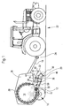
- a drawn harvester 10 in the form of a baler is provided with a chassis 12, a baling chamber 14, wheels 16, a drawbar 18 and a pickup drum 20 and is pulled by a towing vehicle 22, at the rear hitch 24, the drawbar 18 is attached.
- the harvester 10 is formed in the illustrated embodiment as a round baler with a baling chamber 14 fixed size. Instead, another type of press, for. B. a round baler with variable size bale press room, a square baler, a large baler or the like pulled device with a pickup 20 are selected.
- the chassis 12 is formed as a welded assembly and carries side walls 26, between which roller-like pressing elements 28 extend.
- the baling chamber 14 is enclosed laterally by the side walls 26 and peripherally by the pressing elements 28.
- the pressing elements 28 leave at one point from below an inlet 30, can be fed by the crop from the pickup drum 20 in the baling chamber 14.
- the wheels 16 support the chassis 12 and the entire harvester 10 on the ground.
- the drawbar 18 establishes a connection between the chassis 12 and the towing vehicle 22 and extends substantially horizontally above the pick-up drum 20.
- the pickup drum 20 is formed in the manner of a so-called pick-up, d. H. provided with a plurality of circumferential rows of resilient prongs 32 which strip over the ground, thereby lifting on him lying crop and promote back to the inlet 30.
- the tines 32 may be rigidly attached to a central rotor of the take-up drum 20, or their angle with respect to the take-up drum 20 is controlled by cam tracks or other suitable means.
- conveyor rotors 34 may be provided between the take-up drum 20 and the inlet 30.
- the pickup drum 20 is mounted in a known manner in a frame 48 which is a horizontally and transversely to the forward axis extending axis 36 is pivotally mounted to the chassis 12.
- the frame 48 of the pickup drum 20 is supported on the ground by track wheels 38 which are provided on both sides of the pickup drum and guide the pickup drum 20 in a ground-level manner at a constant height above the ground.
- a hold-down 40 is mounted, which is equipped with a front, over the width of the pickup drum 20 extending, freely rotatable about its horizontally and transversely to the forward direction longitudinal axis roller 42 and to limit the recorded by the pickup drum 20 Ernteguthnes serves forwards and upwards.
- the hold-down 40 may also have rigid or flexible or pivotable baffles (not shown) instead of or in addition to the roll 42.
- the hold-down 40 is pivotally hinged at its rear end about a horizontally and transversely to the forward axis 44 to a holder 46, which in turn is connected to the frame 48.
- a first actuator 50 in the form of a single-acting hydraulic cylinder is arranged between the chassis 12 and the frame 48 of the pickup drum 20. If its piston chamber is applied, the frame 48 with the pickup drum 20 from in the FIG. 1 shown operating position about the axis 36 upwards in a non-operating position (not shown) pivoted to move the harvester 10 on a road can.
- a second actuator 52 in the form of a double-acting hydraulic cylinder is arranged between the frame 48 and the hold-down 40. When the piston chamber of the second actuator 52 is acted upon, the hold-down 40 is raised relative to the take-up drum 20, and the hold-down 40 is lowered relative to the take-up drum 20 when the piston rod chamber of the second actuator 52 is acted upon.
- the second actuator 52 is in its lowest possible position.
- the hold-down 40 then follows the movement of the take-up drum 20 caused by the feeler wheels 38 about the axis 36 and its distance from the take-up drum 20 remains constant.
- the hold-down 40 can be raised by means of the second actuator 52 to facilitate the reversing of the take-up drum 20 and / or the rotors 34 for the purpose of eliminating the blockage.
- the hold-down 40 is slidably mounted by the second actuator 52 in the vertical direction.
- a second actuator 52 is present on both sides of the blank holder 40, as well as two first actuators 50 are provided on both sides of the frame 48. It should be noted that the sensing wheels 38 can be omitted if the first actuator 50 (or another suitable actuator) carries out an automatic height control of the pickup drum 20 by means of a suitable sensor, as in FIG DE 100 57 135 A the disclosure of which is incorporated herein by reference.
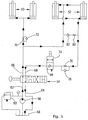
- the FIG. 2 It shows a hydraulic scheme of the control means for controlling the actuators 50, 52. It comprises a selection control valve 54 with two paths and four positions, which is on board the towing vehicle 22 and manually or by external force controlled by the operator of the towing vehicle 22 from his work station , A first input 62 of the selection control valve 54 is connected to a source 56 of pressurized hydraulic fluid, which is designed as a hydraulic pump and in turn connected to a reservoir 58. A pressure relief valve 60 limits the pressure of the source 56 to a desired value. A second input 64 of the selection control valve 54 is connected to the reservoir 58.
- a first output 66 of the selection control valve 54 is connected directly to the piston rod chamber of the second actuators 52 and to the piston chamber of the first actuators 50 via a throttle 70 and a check valve 72 which opens in parallel and opens in the direction of the outlet 66.
- a second output 68 of the selection control valve 54 is connected via a selector valve 74 with a path and two positions and a throttle connected in series 76 and a parallel to the throttle 76, in the direction of the output 68 opening check valve 78 with the piston chamber of the second actuator 52 connected.
- the piston chamber and the piston rod chamber of the second actuator 52 are interconnected by a throttle 80 and a series-connected check valve 82, which could also be omitted.
- the selector valve 74 includes a passage position and a position in which a check valve 84 opening toward the outlet 68 is effective.
- the selector valve 74 may preferably be actuated by the operator from his workstation on the towing vehicle 22, powered by the operator. It is usually on board the harvesting machine 10, while the selection control valve 54 is usually already provided as standard on board the towing vehicle 22.
- FIG. 3 is the hydraulic scheme of FIG. 2 shown in a position in which the selection control valve 54 is in a first passage position in which the pick-up drum 20 is raised while the selector valve 74 is in the blocking position. Accordingly, the piston rod chambers of the actuators 52 are acted upon, so that an optionally raised hold-down 40 lowers and moves out of the piston chambers of the actuators 50 addition hydraulic fluid through the throttle 76 and the check valve 84 to the reservoir 58 moves. Furthermore, the piston chambers of the actuators 50 pass through the throttle 70 pressurized with hydraulic fluid, so that they move the frame 48 with the pickup drum 20 upwards.
- the braked by the throttle 70 movement of the actuator 50 causes the hold-down 40 is already lowered before the pickup drum 20 reaches its inoperative position, which prevents collision of the blank holder 40 with the drawbar 18 or the chassis 12.
- Plotted positions of the valves 54, 74 are used in particular when the harvester 10 has reached a field end and the pick-up drum 20 is to raise before a turning operation is initiated, or before a road trip.
- the position of the valves 54, 74 causes an optionally raised hold-down 40 is lowered before the pickup 50 is raised. Normally, the hold-down 40 is lowered in the harvesting operation, however, so that immediately the take-up drum 20 is raised.
- FIG. 4 is the hydraulic scheme of FIG. 2 shown in a position in which the selection control valve 54 is also in the first passage position in which the pickup drum 20 is raised, while the selector valve 74 is now in the passage position. Accordingly, the piston chambers of the actuators 50 are acted upon by the throttle 70 through with hydraulic fluid, so that they move the frame 48 with the pickup drum 20 upwards. The piston rod chambers of the actuators 52 are also pressurized so that the hold down 40 lowers and the hydraulic fluid forced out of the piston chambers of the actuators 50 moves through the throttle 76 and selector valve 84 to the reservoir 58 at a similar speed as in position to FIG.
- the braked by the throttle 70 movement of the actuator 50 is also here causes the hold-down 40 is already lowered before the pickup drum 20 reaches its inoperative position, which prevents collision of the blank holder 40 with the drawbar 18 or the chassis 12.
- the position of the valves 54 and 74 according to FIG. 4 serves to lower the hold-down 40 after it has been raised to remove a blockage, when then the pick-up drum 20 is to be raised.
- FIG. 5 is the hydraulic scheme of FIG. 2 shown in a position in which the selection control valve 54 is in a second passage position in which the pick-up drum 20 is lowered while the selector valve 74 is in the passage position.
- the piston chambers of the actuators 50 are connected by the throttle 70 and the opening check valve 72 to the reservoir 58, so that the frame 48 moves with the pickup drum 20 due to its own weight down and the hydraulic fluid from the piston chamber of the first actuators 50 in the Reservoir 58 displaced.
- the piston rod chambers of the actuators 52 are now pressurized via the selector valve 74 and the throttle 76, so that the hold-down 40 lifts and the hydraulic fluid forced out of the piston rod chambers of the actuators 52 also moves to the reservoir 58.
- the pressure in the piston chamber of the actuator 50 is limited by the throttle 80 and the check valve 82.
- positions of the selector valve 74 and the selection control valve 54 are suitable for raising the blank holder 40 before a reversing process or slowly to feed clogged crop in the harvester 10, which is facilitated by the raised hold-40.
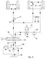
- FIG. 6 is the hydraulic scheme of FIG. 2 shown in a position in which the selection control valve 54 is in the second passage position in which the pick-up drum 20 is lowered while the selector valve 74 is in the blocking position.
- the piston chambers of the actuators 50 are connected by the throttle 70 and the opening check valve 72 to the reservoir 58, so that the frame 48 moves with the pickup drum 20 due to its own weight down and the hydraulic fluid from the piston chamber of the first actuators 50 in the reservoir 58 displaced.
- the hold-down 40 lowers, so that hydraulic fluid from the piston chamber of the second actuator 52 via the throttle 80 and the check valve 82 passes into the piston rod chamber of the second actuator 52.
- positions of the selector valve 74 and the selection control valve 54 are suitable for lowering the blank holder 40 after a reversing process or a slow feeding clogged crop with raised hold-down 40th
- FIG. 7 is the hydraulic scheme of FIG. 2 shown in a position in which the selection control valve 54 is in an open position in which all inputs 62, 64 and all outputs 66, 68 are interconnected, so that the pickup drum 20 is lowered while the selector valve 74 is in the locked position , Accordingly, the piston chambers of the actuators 50 are connected by the throttle 70 and the opening check valve 72 to the reservoir 58, so that the frame 48 moves with the pickup drum 20 due to its own weight down and the hydraulic fluid from the piston chamber of the first actuators 50 in the reservoir 58 displaced. By its own weight, the hold-down 40 lowers, so that hydraulic fluid from the piston chamber of the second actuator 52 via the throttle 80 and the check valve 82 passes into the piston rod chamber of the second actuator 52.
- positions of the selector valve 74 and the selection control valve 54 represent a lowered position for the first actuators 50 and the pickup drum 20 and for the second actuators 52 and the hold-down 40 ready, which is suitable for the normal harvesting operation.
Landscapes
- Life Sciences & Earth Sciences (AREA)
- Environmental Sciences (AREA)
- Harvesting Machines For Specific Crops (AREA)
- Harvesting Machines For Root Crops (AREA)
Claims (6)
- Agencement de réglage de la position d'un tambour ramasseur (20) et d'un élément presseur (40) d'une moissonneuse agricole (10), le tambour ramasseur (20) étant muni de plusieurs rangées périphériques de dents à ressort (32) qui sont disposées de manière à racler le sol et à ainsi soulever la récolte reposant sur le sol et à la transporter vers l'arrière, et l'élément presseur (40) servant à limiter le flux vers l'avant et vers le haut de la récolte ramassée par le tambour ramasseur (20), avec un premier actionneur (50) prévu pour déplacer le tambour ramasseur (20) par rapport à la moissonneuse (10) entre une position de fonctionnement abaissée et une position hors fonctionnement relevée, avec un deuxième actionneur (52) prévu pour le réglage en hauteur de l'élément presseur (40) par rapport au tambour ramasseur (20) et un dispositif de commande connecté aux actionneurs (50, 52), caractérisé en ce que le dispositif de commande est conçu de manière à commander le deuxième actionneur (52) dans le sens d'un déplacement vers le bas de l'élément presseur (40) lorsqu'il commande le premier actionneur (50) de manière à ce qu'il amène le tambour ramasseur (20) dans la position hors fonctionnement.
- Agencement selon la revendication 1, caractérisé en ce que le dispositif de commande est conçu de manière à commander le deuxième actionneur (52) temporellement avant ou simultanément à la commande du premier actionneur (50) de manière à ce qu'il déplace le tambour ramasseur (20) dans la position hors fonctionnement dans le sens d'un déplacement vers le bas de l'élément presseur (40).
- Agencement selon la revendication 1 ou 2, caractérisé en ce que les actionneurs (50, 52) sont des cylindres hydrauliques et en ce que le dispositif de commande comprend une soupape de commande de sélection (54) avec deux entrées (62, 64) et deux sorties (66, 68), dont la première entrée (62) est connectée à une conduite de fluide hydraulique sous pression, dont la deuxième entrée (64) est connectée à un réservoir (58), dont la première sortie est connectée par le biais d'un étranglement (70) et d'un clapet antiretour (72) monté en parallèle avec celui-ci, à une chambre du premier actionneur (50) devant être sollicitée pour relever le tambour ramasseur (20) et à une chambre du deuxième actionneur (52) devant être sollicitée pour abaisser l'élément presseur (40) et dont la deuxième sortie (68) est connectée par le biais d'une soupape de sélection (74) et d'un étranglement (76) monté en série avec celle-ci avec un clapet antiretour (78) monté en parallèle avec l'étranglement (76) à une chambre du deuxième actionneur (52) devant être sollicitée pour relever l'élément presseur (40).
- Moissonneuse (10) comprenant un agencement selon l'une quelconque des revendications 1 à 3.
- Moissonneuse (10) selon la revendication 4, caractérisée en ce que le tambour ramasseur (20) est monté de manière à pouvoir pivoter autour d'un axe (36) s'étendant horizontalement et transversalement à la direction d'avance par rapport à un châssis (12) de la moissonneuse (10) et est guidé de manière à suivre le contour du sol et en ce que l'élément presseur (40) est monté de manière déplaçable en hauteur par rapport au tambour ramasseur (20) ou de manière à pouvoir pivoter autour d'un axe (44) s'étendant horizontalement et transversalement à la direction d'avance.
- Moissonneuse (10) selon la revendication 4 ou 5, caractérisée en ce qu'il s'agit d'une presse à balles tractée, et en ce qu'un timon (18) est monté au-dessus de l'élément presseur (40).
Applications Claiming Priority (1)
| Application Number | Priority Date | Filing Date | Title |
|---|---|---|---|
| DE102007058313.5A DE102007058313B4 (de) | 2007-12-04 | 2007-12-04 | Anordnung zur Verstellung der Position einer Aufnehmertrommel und eines Niederhalters einer landwirtschaftlichen Erntemaschine |
Publications (2)
| Publication Number | Publication Date |
|---|---|
| EP2067399A1 EP2067399A1 (fr) | 2009-06-10 |
| EP2067399B1 true EP2067399B1 (fr) | 2016-04-13 |
Family
ID=40386380
Family Applications (1)
| Application Number | Title | Priority Date | Filing Date |
|---|---|---|---|
| EP08168934.1A Not-in-force EP2067399B1 (fr) | 2007-12-04 | 2008-11-12 | Arrangement de réglage de la position d'un tambour ramasseur et d'un élément presseur d'une moissonneuse agricole |
Country Status (3)
| Country | Link |
|---|---|
| US (1) | US7861506B2 (fr) |
| EP (1) | EP2067399B1 (fr) |
| DE (1) | DE102007058313B4 (fr) |
Cited By (2)
| Publication number | Priority date | Publication date | Assignee | Title |
|---|---|---|---|---|
| US11497169B2 (en) * | 2020-02-27 | 2022-11-15 | Cnh Industrial America Llc | Agricultural vehicle with adjustable pickup |
| WO2023227169A1 (fr) * | 2022-05-25 | 2023-11-30 | Carl Geringhoff Gmbh & Co. Kommanditgesellschaft | Accessoire de ramassage pour machine de récolte |
Families Citing this family (25)
| Publication number | Priority date | Publication date | Assignee | Title |
|---|---|---|---|---|
| US7805914B2 (en) * | 2008-03-10 | 2010-10-05 | Cnh America Llc | Hydraulic bale kicker with optional weighing device |
| US20110023436A1 (en) * | 2009-07-31 | 2011-02-03 | Agco Corporation | Baler Tongue for Collecting Biomass |
| US8443580B2 (en) | 2009-07-31 | 2013-05-21 | Agco Corporation | Baler pickup for collecting biomass from a combine harvester |
| US8490375B2 (en) | 2009-07-31 | 2013-07-23 | Agco Corporation | Baler collector for collecting biomass from a combine harvester |
| US8464508B2 (en) | 2009-07-31 | 2013-06-18 | Agco Corporation | Biomass baler |
| US8800255B2 (en) * | 2011-07-01 | 2014-08-12 | Cnh Industrial America Llc | Arrangement and control of precompression rolls in balers |
| BE1020227A3 (nl) * | 2011-10-10 | 2013-06-04 | Cnh Belgium Nv | Opraapeenheid met beweegbaar windscherm. |
| US8776679B1 (en) * | 2013-03-15 | 2014-07-15 | Cnh Industrial Canada, Ltd. | Semi-automatic bale ejection sequence |
| US9420744B2 (en) * | 2015-01-07 | 2016-08-23 | Cnh Industrial America Llc | Hydraulic system for collecting crop grain and crop residue in a single pass |
| DE102016110985B4 (de) * | 2016-06-15 | 2020-07-09 | Thomas Reiter | Erntegutaufnehmer umfassend einen Rotor |
| CN108725120A (zh) * | 2018-06-04 | 2018-11-02 | 湖南科洋农机制造有限公司 | 一种农业机械的底盘高度自动调节装置 |
| EP3607815B1 (fr) * | 2018-08-07 | 2023-03-22 | Kverneland Group Kerteminde AS | Appareil de traitement agricole |
| US11272659B2 (en) * | 2019-03-27 | 2022-03-15 | Deere & Company | Controlled or tuned float on an agricultural harvester to modify float response |
| US11219162B2 (en) | 2019-04-23 | 2022-01-11 | Deere & Company | Controlled header lowering on an agricultural harvester |
| US11191212B2 (en) | 2019-04-23 | 2021-12-07 | Deere & Company | Controlled float on an agricultural harvester for header leveling |
| US11224164B2 (en) | 2019-04-23 | 2022-01-18 | Deere & Company | Damped float response on an agricultural harvester |
| US12063892B2 (en) * | 2019-08-15 | 2024-08-20 | Kuhn North America, Inc. | Systems, apparatus, and related methods for use with mergers |
| EP3912456B1 (fr) | 2020-05-19 | 2024-12-25 | CNH Industrial Belgium N.V. | Véhicule agricole avec dispositif de retenue pour déblocage de coupe-vent |
| CN112772153B (zh) * | 2020-12-27 | 2022-08-26 | 安徽思嘉瑞机械设备有限公司 | 一种打捆机捡拾器用挤压装置 |
| US12396402B2 (en) * | 2022-01-31 | 2025-08-26 | Cnh Industrial America Llc | Repositionable windguard assembly for agricultural baler feeder system |
| US12396404B2 (en) | 2022-01-31 | 2025-08-26 | Cnh Industrial America Llc | Repositionable windguard assembly for agricultural baler feeder system |
| EP4285711B1 (fr) * | 2022-05-30 | 2025-05-14 | CNH Industrial Belgium N.V. | Élévateur pare-vent pour tête de ramassage d'herbe |
| CN115004953A (zh) * | 2022-05-30 | 2022-09-06 | 内蒙古工业大学 | 一种高品质苜蓿调制设备及其调制方法 |
| CN115076190A (zh) * | 2022-07-20 | 2022-09-20 | 天津轩禾农业机械制造有限公司 | 圆捆机液压系统及圆捆机 |
| US12471513B2 (en) * | 2022-09-07 | 2025-11-18 | Textron Innovations Inc. | Turf mower hydraulic lift control system and method |
Citations (1)
| Publication number | Priority date | Publication date | Assignee | Title |
|---|---|---|---|---|
| EP1046333A1 (fr) * | 1999-04-23 | 2000-10-25 | Deere & Company | Machine de récolte |
Family Cites Families (13)
| Publication number | Priority date | Publication date | Assignee | Title |
|---|---|---|---|---|
| US4516389A (en) * | 1984-09-04 | 1985-05-14 | Core Grant M | Round hay baling machine |
| DE3922695C2 (de) | 1989-06-07 | 2001-06-28 | Claas Saulgau Gmbh | Aufsammler für Erntemaschinen |
| DE3919889A1 (de) | 1989-06-19 | 1990-12-20 | Claas Saulgau Gmbh | Feldhaecksler |
| DE4021030C2 (de) * | 1990-07-03 | 1994-10-06 | Gustav Schumacher | Mähtisch für Erntemaschinen |
| DE4115056B4 (de) | 1991-05-08 | 2007-09-13 | Josef Nusser | Halmgutaufnahmevorrichtung |
| GB9903624D0 (en) * | 1999-02-18 | 1999-04-07 | Ford New Holland Nv | Movable windguard |
| DE29922193U1 (de) | 1999-12-17 | 2001-04-26 | B. Strautmann & Söhne GmbH u. Co, 49196 Bad Laer | Tastvorrichtung zur Höheneinstellung einer Aufnahmetrommel |
| DE10057135A1 (de) * | 2000-11-17 | 2002-05-23 | Deere & Co | Stelleinrichtung eines Aufnehmers für Erntegut |
| DE10120124C2 (de) | 2001-04-25 | 2003-04-30 | Krone Bernhard Gmbh Maschf | Landwirtschaftliche Erntemaschine |
| US6651416B2 (en) * | 2002-02-28 | 2003-11-25 | Deere & Company | Large rectangular baler having hydraulically powered functions, and control system therefor |
| DE10251827A1 (de) * | 2002-11-07 | 2004-06-09 | Deere & Company, Moline | Gutaufnehmer |
| US7617662B2 (en) * | 2005-06-14 | 2009-11-17 | Deere & Company | Integrated crop baffle and hold-down assembly used with baler pick-up and suspension for same |
| US7716910B2 (en) * | 2007-04-24 | 2010-05-18 | Woodford Eric T | Powered rotor for assisting crop pickup for a baler |
-
2007
- 2007-12-04 DE DE102007058313.5A patent/DE102007058313B4/de active Active
-
2008
- 2008-11-12 EP EP08168934.1A patent/EP2067399B1/fr not_active Not-in-force
- 2008-11-26 US US12/324,097 patent/US7861506B2/en active Active
Patent Citations (1)
| Publication number | Priority date | Publication date | Assignee | Title |
|---|---|---|---|---|
| EP1046333A1 (fr) * | 1999-04-23 | 2000-10-25 | Deere & Company | Machine de récolte |
Cited By (2)
| Publication number | Priority date | Publication date | Assignee | Title |
|---|---|---|---|---|
| US11497169B2 (en) * | 2020-02-27 | 2022-11-15 | Cnh Industrial America Llc | Agricultural vehicle with adjustable pickup |
| WO2023227169A1 (fr) * | 2022-05-25 | 2023-11-30 | Carl Geringhoff Gmbh & Co. Kommanditgesellschaft | Accessoire de ramassage pour machine de récolte |
Also Published As
| Publication number | Publication date |
|---|---|
| EP2067399A1 (fr) | 2009-06-10 |
| US20090139195A1 (en) | 2009-06-04 |
| US7861506B2 (en) | 2011-01-04 |
| DE102007058313B4 (de) | 2016-03-10 |
| DE102007058313A1 (de) | 2009-06-10 |
Similar Documents
| Publication | Publication Date | Title |
|---|---|---|
| DE102007058313B4 (de) | Anordnung zur Verstellung der Position einer Aufnehmertrommel und eines Niederhalters einer landwirtschaftlichen Erntemaschine | |
| EP1281312B1 (fr) | Dispositif comportant un ramasseur, un convoyeur et moyen de connexion avec un véhicule | |
| EP1790210B1 (fr) | Dispositif d'alimentation pour une faucheuse-hâcheuse | |
| DE102017222587A1 (de) | Mulchgerät zur Bearbeitung von auf einem Feld stehenden Pflanzenstümpfen mit verstellbarer Position und/oder Bodenandruckkraft | |
| DE102008001779B4 (de) | Erntevorsatz mit einem Gutaufnehmer und einer Querförderschnecke | |
| EP2113396B1 (fr) | Ensemble de roue d'appui pour un ramasseur doté d'un blocage automatique en position de transport | |
| EP3603376B1 (fr) | Machine de récolte doté d'une tête de récolte et d'une roue d'appui | |
| AT513427B1 (de) | Erntewagen zum Aufnehmen und Transport von Pflanzen oder Pflanzenteilen | |
| EP1588601B1 (fr) | Machine de récolte avec un dispositif de décharge | |
| EP1738634B1 (fr) | Dispositif de ramassage de produits de récolte ainsi que machine de récolte. | |
| EP3981245B1 (fr) | Presse agricole pour fourrage et procédé de dépôt des balles de fourrage comprimé | |
| DE102019005662A1 (de) | Auswurfkrümmer für einen Feldhäcksler | |
| EP3959961B1 (fr) | Presse pour produits de récolte à tiges pourvu de module de coupe amovible et procédé de manipulation d'un tel module de coupe amovible | |
| DE102022105847A1 (de) | Schwadaufnehmer mit drittem Stützrad | |
| EP3284335B1 (fr) | Procédé d'inversion d'un ramasseur | |
| BE1026568B1 (de) | Selbstfahrende erntemaschine mit einer überladeeinrichtung | |
| DE102021128945A1 (de) | Rundballenpresse mit einer Vorrichtung | |
| DE102007035744A1 (de) | Kombination aus einem Erntevorsatz und einem Wagen zur Abstützung des Erntevorsatzes und Verfahren zur Ankopplung des Wagens | |
| WO2016118986A1 (fr) | Dispositif pour le chargement et le transport de ballots ronds | |
| DE2553437A1 (de) | Vorrichtung zur handhabung von heu- oder futterballen | |
| EP1932415A1 (fr) | Dispositif muni d'une première et d'une seconde unité de travail | |
| DE102023111687A1 (de) | Klappbares Pick-up-Vorsatzgerät für eine Erntemaschine | |
| EP4442106A1 (fr) | Chariot de ramassage de balles destiné au transport d'une balle, train de travail comprenant une presse à balles rondes et procédé de déchargement de balles d'une telle presse à balles rondes | |
| DE102024103039A1 (de) | Maschine zum Mähen von stängelartigem Erntegut | |
| DE1482235C3 (de) | Mähwerk an landwirtschaftlichen Arbeitsmaschinen, Insbesondere Acker- |
Legal Events
| Date | Code | Title | Description |
|---|---|---|---|
| PUAI | Public reference made under article 153(3) epc to a published international application that has entered the european phase |
Free format text: ORIGINAL CODE: 0009012 |
|
| AK | Designated contracting states |
Kind code of ref document: A1 Designated state(s): AT BE BG CH CY CZ DE DK EE ES FI FR GB GR HR HU IE IS IT LI LT LU LV MC MT NL NO PL PT RO SE SI SK TR |
|
| AX | Request for extension of the european patent |
Extension state: AL BA MK RS |
|
| 17P | Request for examination filed |
Effective date: 20091210 |
|
| 17Q | First examination report despatched |
Effective date: 20100119 |
|
| AKX | Designation fees paid |
Designated state(s): AT BE BG CH CY CZ DE DK EE ES FI FR GB GR HR HU IE IS IT LI LT LU LV MC MT NL NO PL PT RO SE SI SK TR |
|
| GRAP | Despatch of communication of intention to grant a patent |
Free format text: ORIGINAL CODE: EPIDOSNIGR1 |
|
| INTG | Intention to grant announced |
Effective date: 20151112 |
|
| GRAS | Grant fee paid |
Free format text: ORIGINAL CODE: EPIDOSNIGR3 |
|
| GRAA | (expected) grant |
Free format text: ORIGINAL CODE: 0009210 |
|
| AK | Designated contracting states |
Kind code of ref document: B1 Designated state(s): AT BE BG CH CY CZ DE DK EE ES FI FR GB GR HR HU IE IS IT LI LT LU LV MC MT NL NO PL PT RO SE SI SK TR |
|
| REG | Reference to a national code |
Ref country code: GB Ref legal event code: FG4D Free format text: NOT ENGLISH |
|
| REG | Reference to a national code |
Ref country code: AT Ref legal event code: REF Ref document number: 789033 Country of ref document: AT Kind code of ref document: T Effective date: 20160415 Ref country code: CH Ref legal event code: EP |
|
| REG | Reference to a national code |
Ref country code: IE Ref legal event code: FG4D Free format text: LANGUAGE OF EP DOCUMENT: GERMAN |
|
| REG | Reference to a national code |
Ref country code: DE Ref legal event code: R096 Ref document number: 502008014075 Country of ref document: DE |
|
| REG | Reference to a national code |
Ref country code: LT Ref legal event code: MG4D |
|
| REG | Reference to a national code |
Ref country code: NL Ref legal event code: MP Effective date: 20160413 |
|
| PG25 | Lapsed in a contracting state [announced via postgrant information from national office to epo] |
Ref country code: FI Free format text: LAPSE BECAUSE OF FAILURE TO SUBMIT A TRANSLATION OF THE DESCRIPTION OR TO PAY THE FEE WITHIN THE PRESCRIBED TIME-LIMIT Effective date: 20160413 Ref country code: LT Free format text: LAPSE BECAUSE OF FAILURE TO SUBMIT A TRANSLATION OF THE DESCRIPTION OR TO PAY THE FEE WITHIN THE PRESCRIBED TIME-LIMIT Effective date: 20160413 Ref country code: NO Free format text: LAPSE BECAUSE OF FAILURE TO SUBMIT A TRANSLATION OF THE DESCRIPTION OR TO PAY THE FEE WITHIN THE PRESCRIBED TIME-LIMIT Effective date: 20160713 Ref country code: NL Free format text: LAPSE BECAUSE OF FAILURE TO SUBMIT A TRANSLATION OF THE DESCRIPTION OR TO PAY THE FEE WITHIN THE PRESCRIBED TIME-LIMIT Effective date: 20160413 Ref country code: PL Free format text: LAPSE BECAUSE OF FAILURE TO SUBMIT A TRANSLATION OF THE DESCRIPTION OR TO PAY THE FEE WITHIN THE PRESCRIBED TIME-LIMIT Effective date: 20160413 |
|
| PG25 | Lapsed in a contracting state [announced via postgrant information from national office to epo] |
Ref country code: HR Free format text: LAPSE BECAUSE OF FAILURE TO SUBMIT A TRANSLATION OF THE DESCRIPTION OR TO PAY THE FEE WITHIN THE PRESCRIBED TIME-LIMIT Effective date: 20160413 Ref country code: LV Free format text: LAPSE BECAUSE OF FAILURE TO SUBMIT A TRANSLATION OF THE DESCRIPTION OR TO PAY THE FEE WITHIN THE PRESCRIBED TIME-LIMIT Effective date: 20160413 Ref country code: PT Free format text: LAPSE BECAUSE OF FAILURE TO SUBMIT A TRANSLATION OF THE DESCRIPTION OR TO PAY THE FEE WITHIN THE PRESCRIBED TIME-LIMIT Effective date: 20160816 Ref country code: ES Free format text: LAPSE BECAUSE OF FAILURE TO SUBMIT A TRANSLATION OF THE DESCRIPTION OR TO PAY THE FEE WITHIN THE PRESCRIBED TIME-LIMIT Effective date: 20160413 Ref country code: SE Free format text: LAPSE BECAUSE OF FAILURE TO SUBMIT A TRANSLATION OF THE DESCRIPTION OR TO PAY THE FEE WITHIN THE PRESCRIBED TIME-LIMIT Effective date: 20160413 Ref country code: GR Free format text: LAPSE BECAUSE OF FAILURE TO SUBMIT A TRANSLATION OF THE DESCRIPTION OR TO PAY THE FEE WITHIN THE PRESCRIBED TIME-LIMIT Effective date: 20160714 |
|
| PG25 | Lapsed in a contracting state [announced via postgrant information from national office to epo] |
Ref country code: IT Free format text: LAPSE BECAUSE OF FAILURE TO SUBMIT A TRANSLATION OF THE DESCRIPTION OR TO PAY THE FEE WITHIN THE PRESCRIBED TIME-LIMIT Effective date: 20160413 |
|
| REG | Reference to a national code |
Ref country code: DE Ref legal event code: R097 Ref document number: 502008014075 Country of ref document: DE |
|
| PG25 | Lapsed in a contracting state [announced via postgrant information from national office to epo] |
Ref country code: DK Free format text: LAPSE BECAUSE OF FAILURE TO SUBMIT A TRANSLATION OF THE DESCRIPTION OR TO PAY THE FEE WITHIN THE PRESCRIBED TIME-LIMIT Effective date: 20160413 Ref country code: EE Free format text: LAPSE BECAUSE OF FAILURE TO SUBMIT A TRANSLATION OF THE DESCRIPTION OR TO PAY THE FEE WITHIN THE PRESCRIBED TIME-LIMIT Effective date: 20160413 Ref country code: SK Free format text: LAPSE BECAUSE OF FAILURE TO SUBMIT A TRANSLATION OF THE DESCRIPTION OR TO PAY THE FEE WITHIN THE PRESCRIBED TIME-LIMIT Effective date: 20160413 Ref country code: CZ Free format text: LAPSE BECAUSE OF FAILURE TO SUBMIT A TRANSLATION OF THE DESCRIPTION OR TO PAY THE FEE WITHIN THE PRESCRIBED TIME-LIMIT Effective date: 20160413 Ref country code: RO Free format text: LAPSE BECAUSE OF FAILURE TO SUBMIT A TRANSLATION OF THE DESCRIPTION OR TO PAY THE FEE WITHIN THE PRESCRIBED TIME-LIMIT Effective date: 20160413 |
|
| PLBE | No opposition filed within time limit |
Free format text: ORIGINAL CODE: 0009261 |
|
| STAA | Information on the status of an ep patent application or granted ep patent |
Free format text: STATUS: NO OPPOSITION FILED WITHIN TIME LIMIT |
|
| PG25 | Lapsed in a contracting state [announced via postgrant information from national office to epo] |
Ref country code: BE Free format text: LAPSE BECAUSE OF NON-PAYMENT OF DUE FEES Effective date: 20161130 |
|
| 26N | No opposition filed |
Effective date: 20170116 |
|
| PG25 | Lapsed in a contracting state [announced via postgrant information from national office to epo] |
Ref country code: SI Free format text: LAPSE BECAUSE OF FAILURE TO SUBMIT A TRANSLATION OF THE DESCRIPTION OR TO PAY THE FEE WITHIN THE PRESCRIBED TIME-LIMIT Effective date: 20160413 |
|
| REG | Reference to a national code |
Ref country code: DE Ref legal event code: R119 Ref document number: 502008014075 Country of ref document: DE |
|
| REG | Reference to a national code |
Ref country code: CH Ref legal event code: PL |
|
| GBPC | Gb: european patent ceased through non-payment of renewal fee |
Effective date: 20161112 |
|
| PG25 | Lapsed in a contracting state [announced via postgrant information from national office to epo] |
Ref country code: CH Free format text: LAPSE BECAUSE OF NON-PAYMENT OF DUE FEES Effective date: 20161130 Ref country code: LI Free format text: LAPSE BECAUSE OF NON-PAYMENT OF DUE FEES Effective date: 20161130 |
|
| REG | Reference to a national code |
Ref country code: IE Ref legal event code: MM4A |
|
| REG | Reference to a national code |
Ref country code: FR Ref legal event code: ST Effective date: 20170731 |
|
| PG25 | Lapsed in a contracting state [announced via postgrant information from national office to epo] |
Ref country code: LU Free format text: LAPSE BECAUSE OF NON-PAYMENT OF DUE FEES Effective date: 20161130 |
|
| PG25 | Lapsed in a contracting state [announced via postgrant information from national office to epo] |
Ref country code: FR Free format text: LAPSE BECAUSE OF NON-PAYMENT OF DUE FEES Effective date: 20161130 |
|
| PG25 | Lapsed in a contracting state [announced via postgrant information from national office to epo] |
Ref country code: DE Free format text: LAPSE BECAUSE OF NON-PAYMENT OF DUE FEES Effective date: 20170601 Ref country code: IE Free format text: LAPSE BECAUSE OF NON-PAYMENT OF DUE FEES Effective date: 20161112 Ref country code: GB Free format text: LAPSE BECAUSE OF NON-PAYMENT OF DUE FEES Effective date: 20161112 |
|
| REG | Reference to a national code |
Ref country code: AT Ref legal event code: MM01 Ref document number: 789033 Country of ref document: AT Kind code of ref document: T Effective date: 20161112 |
|
| PG25 | Lapsed in a contracting state [announced via postgrant information from national office to epo] |
Ref country code: AT Free format text: LAPSE BECAUSE OF NON-PAYMENT OF DUE FEES Effective date: 20161112 |
|
| REG | Reference to a national code |
Ref country code: BE Ref legal event code: MM Effective date: 20161130 |
|
| PG25 | Lapsed in a contracting state [announced via postgrant information from national office to epo] |
Ref country code: HU Free format text: LAPSE BECAUSE OF FAILURE TO SUBMIT A TRANSLATION OF THE DESCRIPTION OR TO PAY THE FEE WITHIN THE PRESCRIBED TIME-LIMIT; INVALID AB INITIO Effective date: 20081112 Ref country code: CY Free format text: LAPSE BECAUSE OF FAILURE TO SUBMIT A TRANSLATION OF THE DESCRIPTION OR TO PAY THE FEE WITHIN THE PRESCRIBED TIME-LIMIT Effective date: 20160413 |
|
| PG25 | Lapsed in a contracting state [announced via postgrant information from national office to epo] |
Ref country code: MC Free format text: LAPSE BECAUSE OF FAILURE TO SUBMIT A TRANSLATION OF THE DESCRIPTION OR TO PAY THE FEE WITHIN THE PRESCRIBED TIME-LIMIT Effective date: 20160413 Ref country code: IS Free format text: LAPSE BECAUSE OF FAILURE TO SUBMIT A TRANSLATION OF THE DESCRIPTION OR TO PAY THE FEE WITHIN THE PRESCRIBED TIME-LIMIT Effective date: 20160413 Ref country code: TR Free format text: LAPSE BECAUSE OF FAILURE TO SUBMIT A TRANSLATION OF THE DESCRIPTION OR TO PAY THE FEE WITHIN THE PRESCRIBED TIME-LIMIT Effective date: 20160413 |
|
| PG25 | Lapsed in a contracting state [announced via postgrant information from national office to epo] |
Ref country code: BG Free format text: LAPSE BECAUSE OF FAILURE TO SUBMIT A TRANSLATION OF THE DESCRIPTION OR TO PAY THE FEE WITHIN THE PRESCRIBED TIME-LIMIT Effective date: 20160413 |
|
| PG25 | Lapsed in a contracting state [announced via postgrant information from national office to epo] |
Ref country code: MT Free format text: LAPSE BECAUSE OF FAILURE TO SUBMIT A TRANSLATION OF THE DESCRIPTION OR TO PAY THE FEE WITHIN THE PRESCRIBED TIME-LIMIT Effective date: 20160413 |