EP3603598B1 - Hautverletzungsresistente insassenstützstruktur - Google Patents
Hautverletzungsresistente insassenstützstruktur Download PDFInfo
- Publication number
- EP3603598B1 EP3603598B1 EP19188937.7A EP19188937A EP3603598B1 EP 3603598 B1 EP3603598 B1 EP 3603598B1 EP 19188937 A EP19188937 A EP 19188937A EP 3603598 B1 EP3603598 B1 EP 3603598B1
- Authority
- EP
- European Patent Office
- Prior art keywords
- occupant
- bladder
- heel region
- support structure
- mattress
- Prior art date
- Legal status (The legal status is an assumption and is not a legal conclusion. Google has not performed a legal analysis and makes no representation as to the accuracy of the status listed.)
- Active
Links
Images








Classifications
-
- A—HUMAN NECESSITIES
- A61—MEDICAL OR VETERINARY SCIENCE; HYGIENE
- A61G—TRANSPORT, PERSONAL CONVEYANCES, OR ACCOMMODATION SPECIALLY ADAPTED FOR PATIENTS OR DISABLED PERSONS; OPERATING TABLES OR CHAIRS; CHAIRS FOR DENTISTRY; FUNERAL DEVICES
- A61G7/00—Beds specially adapted for nursing; Devices for lifting patients or disabled persons
- A61G7/002—Beds specially adapted for nursing; Devices for lifting patients or disabled persons having adjustable mattress frame
- A61G7/015—Beds specially adapted for nursing; Devices for lifting patients or disabled persons having adjustable mattress frame divided into different adjustable sections, e.g. for Gatch position
-
- A—HUMAN NECESSITIES
- A61—MEDICAL OR VETERINARY SCIENCE; HYGIENE
- A61G—TRANSPORT, PERSONAL CONVEYANCES, OR ACCOMMODATION SPECIALLY ADAPTED FOR PATIENTS OR DISABLED PERSONS; OPERATING TABLES OR CHAIRS; CHAIRS FOR DENTISTRY; FUNERAL DEVICES
- A61G7/00—Beds specially adapted for nursing; Devices for lifting patients or disabled persons
- A61G7/05—Parts, details or accessories of beds
- A61G7/065—Rests specially adapted therefor
- A61G7/075—Rests specially adapted therefor for the limbs
- A61G7/0755—Rests specially adapted therefor for the limbs for the legs or feet
-
- A—HUMAN NECESSITIES
- A61—MEDICAL OR VETERINARY SCIENCE; HYGIENE
- A61G—TRANSPORT, PERSONAL CONVEYANCES, OR ACCOMMODATION SPECIALLY ADAPTED FOR PATIENTS OR DISABLED PERSONS; OPERATING TABLES OR CHAIRS; CHAIRS FOR DENTISTRY; FUNERAL DEVICES
- A61G7/00—Beds specially adapted for nursing; Devices for lifting patients or disabled persons
- A61G7/002—Beds specially adapted for nursing; Devices for lifting patients or disabled persons having adjustable mattress frame
- A61G7/018—Control or drive mechanisms
-
- A—HUMAN NECESSITIES
- A61—MEDICAL OR VETERINARY SCIENCE; HYGIENE
- A61G—TRANSPORT, PERSONAL CONVEYANCES, OR ACCOMMODATION SPECIALLY ADAPTED FOR PATIENTS OR DISABLED PERSONS; OPERATING TABLES OR CHAIRS; CHAIRS FOR DENTISTRY; FUNERAL DEVICES
- A61G7/00—Beds specially adapted for nursing; Devices for lifting patients or disabled persons
- A61G7/05—Parts, details or accessories of beds
-
- A—HUMAN NECESSITIES
- A61—MEDICAL OR VETERINARY SCIENCE; HYGIENE
- A61G—TRANSPORT, PERSONAL CONVEYANCES, OR ACCOMMODATION SPECIALLY ADAPTED FOR PATIENTS OR DISABLED PERSONS; OPERATING TABLES OR CHAIRS; CHAIRS FOR DENTISTRY; FUNERAL DEVICES
- A61G7/00—Beds specially adapted for nursing; Devices for lifting patients or disabled persons
- A61G7/05—Parts, details or accessories of beds
- A61G7/057—Arrangements for preventing bed-sores or for supporting patients with burns, e.g. mattresses specially adapted therefor
-
- A—HUMAN NECESSITIES
- A61—MEDICAL OR VETERINARY SCIENCE; HYGIENE
- A61G—TRANSPORT, PERSONAL CONVEYANCES, OR ACCOMMODATION SPECIALLY ADAPTED FOR PATIENTS OR DISABLED PERSONS; OPERATING TABLES OR CHAIRS; CHAIRS FOR DENTISTRY; FUNERAL DEVICES
- A61G7/00—Beds specially adapted for nursing; Devices for lifting patients or disabled persons
- A61G7/05—Parts, details or accessories of beds
- A61G7/065—Rests specially adapted therefor
-
- A—HUMAN NECESSITIES
- A61—MEDICAL OR VETERINARY SCIENCE; HYGIENE
- A61G—TRANSPORT, PERSONAL CONVEYANCES, OR ACCOMMODATION SPECIALLY ADAPTED FOR PATIENTS OR DISABLED PERSONS; OPERATING TABLES OR CHAIRS; CHAIRS FOR DENTISTRY; FUNERAL DEVICES
- A61G7/00—Beds specially adapted for nursing; Devices for lifting patients or disabled persons
- A61G7/05—Parts, details or accessories of beds
- A61G7/065—Rests specially adapted therefor
- A61G7/07—Rests specially adapted therefor for the head or torso, e.g. special back-rests
-
- A—HUMAN NECESSITIES
- A61—MEDICAL OR VETERINARY SCIENCE; HYGIENE
- A61G—TRANSPORT, PERSONAL CONVEYANCES, OR ACCOMMODATION SPECIALLY ADAPTED FOR PATIENTS OR DISABLED PERSONS; OPERATING TABLES OR CHAIRS; CHAIRS FOR DENTISTRY; FUNERAL DEVICES
- A61G2203/00—General characteristics of devices
- A61G2203/70—General characteristics of devices with special adaptations, e.g. for safety or comfort
- A61G2203/74—General characteristics of devices with special adaptations, e.g. for safety or comfort for anti-shear when adjusting furniture
-
- A—HUMAN NECESSITIES
- A61—MEDICAL OR VETERINARY SCIENCE; HYGIENE
- A61G—TRANSPORT, PERSONAL CONVEYANCES, OR ACCOMMODATION SPECIALLY ADAPTED FOR PATIENTS OR DISABLED PERSONS; OPERATING TABLES OR CHAIRS; CHAIRS FOR DENTISTRY; FUNERAL DEVICES
- A61G7/00—Beds specially adapted for nursing; Devices for lifting patients or disabled persons
- A61G7/002—Beds specially adapted for nursing; Devices for lifting patients or disabled persons having adjustable mattress frame
- A61G7/012—Beds specially adapted for nursing; Devices for lifting patients or disabled persons having adjustable mattress frame raising or lowering of the whole mattress frame
-
- A—HUMAN NECESSITIES
- A61—MEDICAL OR VETERINARY SCIENCE; HYGIENE
- A61G—TRANSPORT, PERSONAL CONVEYANCES, OR ACCOMMODATION SPECIALLY ADAPTED FOR PATIENTS OR DISABLED PERSONS; OPERATING TABLES OR CHAIRS; CHAIRS FOR DENTISTRY; FUNERAL DEVICES
- A61G7/00—Beds specially adapted for nursing; Devices for lifting patients or disabled persons
- A61G7/05—Parts, details or accessories of beds
- A61G7/0501—Bed-clothes supports to alleviate the weight of the bed-clothes on the patient
-
- A—HUMAN NECESSITIES
- A61—MEDICAL OR VETERINARY SCIENCE; HYGIENE
- A61G—TRANSPORT, PERSONAL CONVEYANCES, OR ACCOMMODATION SPECIALLY ADAPTED FOR PATIENTS OR DISABLED PERSONS; OPERATING TABLES OR CHAIRS; CHAIRS FOR DENTISTRY; FUNERAL DEVICES
- A61G7/00—Beds specially adapted for nursing; Devices for lifting patients or disabled persons
- A61G7/05—Parts, details or accessories of beds
- A61G7/057—Arrangements for preventing bed-sores or for supporting patients with burns, e.g. mattresses specially adapted therefor
- A61G7/05715—Arrangements for preventing bed-sores or for supporting patients with burns, e.g. mattresses specially adapted therefor with modular blocks, or inserts, with layers of different material
-
- A—HUMAN NECESSITIES
- A61—MEDICAL OR VETERINARY SCIENCE; HYGIENE
- A61G—TRANSPORT, PERSONAL CONVEYANCES, OR ACCOMMODATION SPECIALLY ADAPTED FOR PATIENTS OR DISABLED PERSONS; OPERATING TABLES OR CHAIRS; CHAIRS FOR DENTISTRY; FUNERAL DEVICES
- A61G7/00—Beds specially adapted for nursing; Devices for lifting patients or disabled persons
- A61G7/05—Parts, details or accessories of beds
- A61G7/057—Arrangements for preventing bed-sores or for supporting patients with burns, e.g. mattresses specially adapted therefor
- A61G7/0573—Arrangements for preventing bed-sores or for supporting patients with burns, e.g. mattresses specially adapted therefor with mattress frames having alternately movable parts
-
- A—HUMAN NECESSITIES
- A61—MEDICAL OR VETERINARY SCIENCE; HYGIENE
- A61G—TRANSPORT, PERSONAL CONVEYANCES, OR ACCOMMODATION SPECIALLY ADAPTED FOR PATIENTS OR DISABLED PERSONS; OPERATING TABLES OR CHAIRS; CHAIRS FOR DENTISTRY; FUNERAL DEVICES
- A61G7/00—Beds specially adapted for nursing; Devices for lifting patients or disabled persons
- A61G7/05—Parts, details or accessories of beds
- A61G7/057—Arrangements for preventing bed-sores or for supporting patients with burns, e.g. mattresses specially adapted therefor
- A61G7/05769—Arrangements for preventing bed-sores or for supporting patients with burns, e.g. mattresses specially adapted therefor with inflatable chambers
-
- A—HUMAN NECESSITIES
- A61—MEDICAL OR VETERINARY SCIENCE; HYGIENE
- A61G—TRANSPORT, PERSONAL CONVEYANCES, OR ACCOMMODATION SPECIALLY ADAPTED FOR PATIENTS OR DISABLED PERSONS; OPERATING TABLES OR CHAIRS; CHAIRS FOR DENTISTRY; FUNERAL DEVICES
- A61G7/00—Beds specially adapted for nursing; Devices for lifting patients or disabled persons
- A61G7/05—Parts, details or accessories of beds
- A61G7/057—Arrangements for preventing bed-sores or for supporting patients with burns, e.g. mattresses specially adapted therefor
- A61G7/05769—Arrangements for preventing bed-sores or for supporting patients with burns, e.g. mattresses specially adapted therefor with inflatable chambers
- A61G7/05776—Arrangements for preventing bed-sores or for supporting patients with burns, e.g. mattresses specially adapted therefor with inflatable chambers with at least two groups of alternately inflated chambers
Definitions
- the subject matter described herein relates to occupant support structures having features for resisting skin injuries to an occupant of the support structure, and associated methods for resisting skin injuries.
- the frame may have a torso segment, a seat segment, a thigh segment, and a calf/foot segment corresponding approximately to the torso, buttocks, thighs, and calves/feet of a patient occupying the bed. At least some of the segments are rotatable about respective laterally extending axes so that the profile of the bed can be adjusted.
- a mattress resides on the frame. The mattress flexes in response to changes in the angular orientation of the rotatable frame segments so that the mattress profile mimics the frame profile.
- a patient who is reasonably capable of moving around in the bed may move enough that his feet temporarily break contact with the mattress, allowing the stretched skin to relax back to its unstretched, injury resistant state.
- a nurse can temporarily lift the patient's feet off the mattress so that the stretched skin can relax.
- US 6012186 discloses an apparatus is to support a mattress.
- the apparatus includes a base platform that is formed to rest on a box spring and to include slots therethrough, a plate hinged to the base platform, and a bladder fastened between the plate and the base platform.
- the present invention may comprise one or more of the following features or combinations thereof.
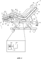
- a hospital bed 20 extends longitudinally from a head end H to a foot end F and laterally from a left side (visible in the plane of the illustration) to a right side.
- the bed includes a base frame 22 and an elevatable frame 24 supported from and connected to the base frame by, for example, rotatable links 26.
- Actuators 30 drive the links to change the elevation of the elevatable frame relative to the base frame.
- a user directs operation of actuators 30 by way of a user interface such as a keypad 32.
- the elevatable frame includes a deck comprising a torso or upper body segment 40 corresponding approximately to the torso of an occupant or patient, a seat segment 42 corresponding approximately to the occupant's buttocks, a thigh segment 44 corresponding approximately to the occupant's thighs, and a calf segment 46 corresponding approximately to the occupant's calves and feet.
- the seat, thigh and calf segments define a lower body segment 48.
- Deck segment actuators 60 are operable to rotate the torso, thigh, and calf segments segments thereby adjusting orientation angles ⁇ , ⁇ , and ⁇ of those segments.
- the thigh and calf segments are rotatably joined to each other at a joint or hinge 62 so that angles ⁇ , ⁇ , and ⁇ , are interdependent.
- the angular orientations of the torso, seat, thigh and calf deck segments define the profile of the deck. Deck segment rotations away from horizontal (and the accompanying changes of the orientation angle) are considered to be positive. Deck segment rotations toward horizontal (and the accompanying changes of the orientation angle) are considered to be negative.
- the phrase "away from horizontal” means an increase in angle ⁇ even if ⁇ is not initially zero.
- “toward horizontal” means a decrease in angle ⁇ even if ⁇ is not zero after the change is complete.
- a user directs operation of deck segment actuators 60 by way of a user interface such as keypad 32.
- the bed also includes a mattress 70 supported on the deck.
- the illustrated mattress includes a ticking 72 which encloses one or more support components.
- Typical support components include foam blocks, bladders pressurized with a gas (typically air), and combinations of foam and bladders.
- Support bladders may be factory inflated and sealed or may be actively inflatable and deflatable during use to carry out therapy, prevent detrimental changes in the patient's condition, or enhance patient comfort.
- inflatable when applied to a bladder, means inflatable and deflatable unless stated otherwise.
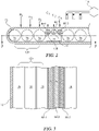
- the support component of the mattress illustrated in FIGS. 1-3 includes a set of longitudinally distributed main support bladders 76 and one or more heel relief bladders 80.
- the illustrated main bladders and heel relief bladders are all appropriately pressurized to provide sustained support to the occupant.
- Sustained support is long duration support as distinct from transient support which is provided temporarily by the heel relief bladders to counteract stretching of the occupant's skin, as described more thoroughly below.
- only the main bladders are pressurized to provide sustained support in the heel region subsection 120. (The heel region subsection is described in more depth below.)
- the heel relief bladders are unpressurized or are only slightly pressurized so that they play no meaningful role in sustained support of the occupant. Instead, the heel relief bladders are essentially collapsed between the mattress ticking and whatever component resides underneath the heel relief bladders.
- the mattress can be thought of as having torso, seat, thigh, and calf/foot sections 90, 92, 94, 96 corresponding to the torso, seat, thigh and calf/foot segments of the deck.
- the seat, thigh, and calf sections define a lower body section 98.
- the mattress is flexible enough to conform to the profile of the deck as governed by the deck segment actuators 60. That is, the mattress flexes in response to a change of orientation of one or more deck segments.
- the angles ⁇ , ⁇ , ⁇ , and ⁇ used to indicate the orientations of the deck segments are therefore also used to describe the orientations of the mattress sections.
- mattress sections 90, 92, 94, 96 are considered to be orientation adjustable even though their orientations are effected by the orientation of the deck segments rather than being governed directly by actuators.
- references to a change in the orientation of one of the mattress sections should be understood to be a change in the orientation of the mattress section as driven by the corresponding deck segment.
- the concepts described herein are applicable to beds having mattress sections that are orientation adjustable independently of orientation adjustment of a deck segment or segments.
- Such a mattress is described in US Patent 8,146,187 entitled “Mattress and Mattress Replacement System with and [sic] Intrinsic Contour Feature".
- the occupant support structure also includes a control system.
- the control system includes a processor 110, a memory 112, and a set of machine readable instructions 114 stored in the memory.
- the processor receives directives from a user, for example by way of keypad 32.
- the processor executes appropriate machine readable instructions from the instruction set and issues commands required to carry out the user's directive.
- References in this specification to the operation, functioning or actions of the processor mean the actions undertaken by the processor in response to instructions from instruction set 114 that are appropriate to the directive from the user. For example a user may press a keypad button to direct an increase in the orientation angle ⁇ of torso frame segment 40.
- the processor executes instructions from instruction set 114 which cause actuator 60-2 to operate in a way that increases torso angle ⁇ .
- the occupant support system also includes an air pump or blower 118 and associated plumbing and valves for pressurizing at least an array of heel relief bladders 80.
- the heel relief bladders can also be partially or completely depressurized by operating the pump in reverse to apply suction to the bladders or by simply venting the bladders to the atmosphere.
- Mattress lower body section 98 includes a heel region subsection 120.
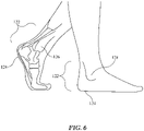
- the occupant's heel region 122 When an occupant is correctly positioned on the occupant support structure, the occupant's heel region 122 is longitudinally aligned with mattress heel region subsection 120 so that the heel region subsection supports at least part of the occupant's heel region.
- Heel region subset 120 is longitudinally long enough to accommodate a range of patients from short to tall. Referring to FIG. 6 , the occupant's heel region 122 extends from the heel 124 itself to just past the ankle or, more technically, just beyond the medial malleolus 126 on the medial side of the foot and just beyond the lateral malleolus 128 on the lateral side of the foot.
- Inclusion of the medial malleolus and the lateral malleolus in the definition of the heel region reflects the fact that both of those anatomical features are prominences which could be subject to skin stretching and shear similar to that described above for the heel. This may be particularly true if the patient is not supine or if his leg is bent at the knee when the orientation of the torso section undergoes a change.
- Mattress lower body section 98 also includes at least one heel relief bladder 80.
- the heel relief bladders provide temporary support to counteract skin stretch in the vicinity of the occupant's heels.
- the lower body section includes an array of multiple heel relief bladders 80 sufficiently pressurized to provide sustained support to the portion of the occupant's body above the heel relief bladders. These include a footwardmost bladder 80-1, a headwardmost bladder 80-3 and an intermediate bladder 80-2.
- the example of FIGS. 4-5 includes an array of multiple heel relief bladders 80 which are not sufficiently pressurized to provide sustained support to the portion of the occupant's body above the heel relief bladders.
- FIGS. 4-5 includes an array of multiple heel relief bladders 80 which are not sufficiently pressurized to provide sustained support to the portion of the occupant's body above the heel relief bladders.
- the mattress lower body section includes a single heel relief bladder 80 sufficiently pressurized to provide sustained support to the portion of the occupant's body above the heel relief bladders.
- the mattress lower body section includes a single heel relief bladder 80 not sufficiently pressurized to provide sustained support to the portion of the occupant's body above the heel relief bladders.
- the variants of FIGS. 7-8 and 10 may be thought of as the limit case in which the heel relief bladder array is a single bladder.
- the heel relief bladder array is located headwardly of heel region subsection 120, for example at a location longitudinally aligned with the location of the occupant's calves.
- the heel relief bladder or bladders rest atop a relatively stiff reaction plate 102, which itself is supported by main bladder 76.
- the control system relieves the skin stretch by virtue of being adapted to cause mattress heel region subsection 120 to temporarily substantially disengage from the heel region 122 of the occupant in response to a change of angular orientation of the torso section which begins at a time t 0 .
- the heel relief bladder array is inflatable to effect disengagement of the occupant's heel region 122 from mattress heel region subsection 120. The disengagement provides an opportunity for the occupant's stretched skin to return to its unstretched state.
- the control system is also adapted to cause the heel region subsection to subsequently re-engage with the heel region of the occupant.
- the bladder array is deflatable to effect re-engagement of the occupant's heel region with the mattress heel region subsection.
- the re-engagement occurs at a time t B which is later than t 0 .
- Reaction plate 102 helps react forces arising from use of the heel relief bladder or bladders to disengage the occupant's heel region 122 from mattress heel region subsection 120.
- the reaction plate may not be necessary if the main bladder is satisfactory for reacting the forces on its own.
- substantially disengaged includes a complete loss of contact between the occupant's heel region 122 and the heel region subsection 120 of the mattress, but also includes light contact between the occupant's heel region and the heel region subsection of the mattress.
- Light contact constitutes substantial disengagement if the force or forces tending to return the occupant's skin from its stretched state to the relaxed state are large enough to overcome the forces tending to keep the skin in its stretched state. The lighter the contact, the more quickly the skin will return to its relaxed state.
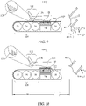
- FIGS. 9-11 are a sequence of views showing a method of resisting skin injuries, and actions carried out by the processor and machine readable instructions of FIG. 1 in order to operate the heel relief bladder or bladders of FIGS. 1-3 , 4-5 , 7-8 , and 9.
- FIG. 12 is an associated set of graphs. Referring first to FIGS. 9 and 12 , at time t 0 the mattress torso section 40 is at an orientation ⁇ 1 , but begins responding to a command to change its orientation away from horizontal. (Only the mattress ticking is shown in the torso section of FIGS. 9-11 ; the support components are omitted in the interest of clarity.) At time t 1 the orientation change is complete.
- the control system commands inflation of heel relief bladder 80.
- inflation of the heel relief bladder lifts the occupant's calves and therefore lifts his heels so that they are substantially disengaged from heel region subsection 120 of mattress lower body section 98.
- the force or forces that had been stretching the skin in the vicinity of the occupant's heels are no longer present, and the skin relaxes back to its unstretched state as indicated by the vertical hash marks on the occupant's heels.
- the support provided by the heel relief bladders when inflated to disengage the occupant's heel region from the heel region subsection of the mattress as seen in FIG. 10 , is temporary support, not the sustained support previously described.
- the heel relief bladders are not inflated to effect disengagement of the occupant's heel region from the heel region subsection of the mattress, but are inflated as in FIGS. 1-3 and 7-8, they are considered to be contributing to the sustained support provided by the mattress.
- the control system then commands deflation of the heel relief bladder 80.
- deflation of the heel relief bladder causes the occupant's calves to re-engage with the mattress lower body section and causes his heel region 122 to re-engage with mattress heel region subsection 120.
- the re-engagement occurs at a time t B , which is later than time t A and preferably later than time t 1 .
- the occupant's skin remains in the relaxed state as indicated by the vertical hash marks.
- the occupant's heel region 120 and mattress heel region subsection 122 remain engaged with each other until another torso section orientation change occurs.
- the re-engagement of the occupant's heel region with the mattress heel region subsection marks the conclusion of the actions for addressing the heel region skin stretch resulting from the orientation change of the upper body section during the time interval from t 0 to t 1 .
- the heel relief action is repeatable by the control system in the event of a subsequent additional change of torso angle ⁇ . This is seen in the sequence of events in the interval corresponding to the primed time coordinates of FIG. 12 .
- control system is adapted to cause the temporary substantial disengagement and the subsequent re-engagement of the occcupant's heel region and the mattress heel region subsection only if the angular orientation of the torso section changes in the positive direction, i.e. away from horizontal. Nevertheless, the risk of skin injury during negative changes cannot be ruled out or dismissed as trivial. Therefore in another embodiment the control system is adapted to cause the temporary substantial disengagement and the subsequent re-engagement of the occcupants's heel region and the mattress heel region subsection irrespective of the direction of torso angle change. Heel relief actions carried out in response to a negative change in torso angle is shown at the double primed time coordinates of FIG. 12 .
- step changes in the graphs of FIG. 12 are idealizations. For example there will be some time delay between the onset of inflation (or deflation) at points Q and the conclusion of inflation (or deflation) at points R.
- the action to disengage the occupant's heel region from the mattress heel region subsection begins at time t A which is no earlier than t 1 .
- t A is approximately equal to t 1 .
- t A may be prior to t 1 if disengaging the patient's heel region from the mattress heel region subsection while torso angle ⁇ is changing is not contraindicated.
- deferring the disengagement until the change of torso angle is complete may have benefits. For example if there are multiple heel relief bladders, one of those bladders will likely be the bladder best suited for disengaging the occupant's heel region from the heel region subsection of the mattress.
- Which bladder is most suitable may depend on where the patient's calves are positioned relative to the heel relief bladders.
- the extent to which the torso orientation change pushes the occupant toward the foot end of the bed affects the spatial relationship between the occupant's calves and the individual members of the array of multiple heel relief bladders. Therefore waiting until the torso orientation change is complete, and the occupant is completely migrated, helps ensure accurate identification of the preferred bladder.
- the bladder may include a transducer 140 such as pressure transducer 140P.
- the control system may be adapted to compare the actual bladder pressure P BLADDER to one or more pressure limits such as the upper and/or lower bounds P UPPER , P LOWER of FIG. 13 .
- the control system is also adapted to take corrective action if the actual pressure violates a limit.
- the corrective action may comprise termination of, and possibly reversal of, the inflation of the heel relief bladder. Referring additionally to FIG. 14 , such deviation may be the result of, for example, patient mispositioning on the bed such that the heel relief bladder is in zone X, too close to his ankle, or zone Z, too close to his knee.
- the termination or reversal of bladder inflation reflects a belief that applying a lifting force outside of zone Y may be ineffective in disengaging the occupant's heel region from the mattress heel region subsection or a belief that applying a lifting force outside of zone Y is inadvisable.
- FIGS. 9- 12 The method and actions described above are in connection with FIGS. 9- 12 and therefore are in the context of a single heel relief bladder which is not initially pressurized enough (i.e. prior to time t A ) to sufficiently support the portion of the occupant's body above the bladder.
- the same description applies to the bladder arrays of of FIGS. 1-3 , FIGS. 4-5 , and FIGS. 7-8 .
- inflation of the bladder array may involve inflation of all the bladders of the array.
- inflation of the bladder array may involve inflation of fewer than all members of the array.
- FIGS. 15-17 (and the graphs of FIG. 12 ) repeat the example of FIGS. 9-11 for an array of multiple bladders.
- the multiple bladder arrays offer additional functionality due to the option to inflate fewer than all of the bladders of the array.
- each bladder may include a transducer 140 such as a pressure transducer 140P.
- the control system is adapted to select a subset of the heel relief bladders 80 and to inflate and deflate only the subset to effect the disengagement of the occupant's heel region 122 from mattress heel region subsection 120 and subsequent re-engagement of the occupant's heel region with the mattress heel region subsection.
- the subset is a single heel relief bladder of the multi-bladder array.
- the longitudinal distribution of the bladders, and the adaptation of the control system to select only a subset of the bladders for inflation and deflation helps ensure that the bladder subset, when inflated, acts on zone Y of the occupant's calf rather than on zones X or Z.
- the occupant support structure accommodates occupants of differing heights. For example, referring to FIG. 2 , if the occupant is tall, his heel region might reside at location H 1 , and the approximate center of calf zone Y might reside at location C 1 . It would therefore be appropriate to employ heel relief bladder 80-1 to carry out the disengagement and re-engagement of the occupants' heel region 122 and mattress heel region subsection 120.
- heel relief bladder 80-2 to carry out the disengagement and re-engagement. If the occupant is short his heel region might reside at location H 3 , and the approximate center of zone Y of his calf might reside at location C 3 . It would therefore be appropriate to employ heel relief bladder 80-3 to carry out the disengagement and re-engagement.
- control system may be adapted to command a test inflation of each of the bladders and to include in the selected subset whichever bladder the test inflation reveals to be most suitable to effect the engagement and disengagement.
- the test inflation involves partial inflation of all the bladders of the heel relief bladder array, either sequentially or concurrently (block 200).
- Partial inflation means inflation or pressurization less than that necessary to substantially disengage of the occupant's heel region from the mattress heel region subsection.
- Processor 110 executes appropriate instructions of the machine readable instruction set 114 to analyze the readings from transducers 140.
- processor 110 uses the results of the analysis to select whichever bladder the test inflation reveals to be most suitable to effect the disengagement. In one embodiment suitability is judged by determining which bladder is most heavily loaded by the test inflation (i.e. which bladder exhibits the highest internal pressure).
- processor 110 includes only that bladder in the subset (block 204).
- processor 110 commands inflation and deflation of that bladder to effect the disengagement of the occupant's heel region from the mattress heel region subsection.
- the test inflation of the nonselected bladders may be reversed (i.e. the nonselected bladders may be deflated) or the nonselected bladders may be left temporarily in their partially inflated test state and deflated at a later time.
- the processor determines whether the time to depressurize the bladder subset has arrived. The determination could be in the form of a specified time delay relative to time t A . If not, pressurization is maintained (block 210). If so, the bladder subset is depressurized at block 212. If the nonselected heel relief bladders were previously left in their test state, those bladders are also deflated to their original state. As already noted, the original state may be one of sufficient inflation to provide sustained support of the portion of the occupant's body above the heel relief bladders, or may be a state in which the heel relief bladders do not provide any meaningful sustained support to the occupant.
- the control system may be adapted to inflate the selected bladders concurrently or at least partially nonconcurrently.
- nonconcurrent inflation is sequential inflation beginning with the headwardmost bladder and proceed progressively toward the footwardmost bladder (80-1, 80-2, 80-3) or vice versa.
- a nonprogressive inflation e.g. 80-2, 80-1, 80-3.
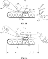
- FIGS. 40-41 , 44-45 and 46-48 of pending, commonly owned US Provisional Patent Application 62/667,769 entitled “Patient Support Surface Control, End of Life Indication, and X-Ray Cassette Sleeve” filed on May 7, 2018 show pneumatic arrangements in which an adjustment to the mattress disengages the heel region subsection of the mattress from the heel region of the occupant by elevating the occupant's calves, albeit not in response to elevation of the torso section of the disclosed occupant support structure.
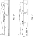
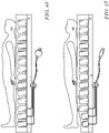
- the substantive content of FIGS. 40-41 , 44-45 and 46-48 of the '769 application are reproduced as FIGS. 19-20 , 21-22 and 23-25 of the present application for the convenience of the reader.
- FIGS. 49-50 , 51-52 , 53-54 and 55-56 of application 62/667,769 show non-pneumatic adjustments of the mattress.
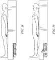
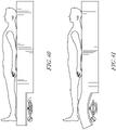
- FIGS. 34-35 , 30-37 , 38-39 , 57-58 and 59-60 of application 62/667,769 the substance of which are reproduced as FIGS. 34-35 , 36-37 , 38-39 , 40-41 and 42-43 of this application.
- the frame component of the occupant support structure includes a mechanism which is operable to cause the mattress heel region subsection to disengage from and re-engage with the heel region of the occupant.
- the control system is adapted to temporarily substantially disengage the mattress heel region subsection 120 from an anatomical region of concern, and to cause subsequent re-engagement, by controlling a mattress component which is longitudinally offset from the anatomical region of concern.
- the control system controls inflation of the heel relief bladder or bladders 80, which are longitudinally offset from the occupant's heel region 122 and from mattress heel region subsection 120.
- control system is adapted to temporarily substantially disengage the mattress heel region subsection 120 from the occupant's heel region 122, and to cause subsequent re-engagement, by controlling a component of the occupant support structure which is longitudinally aligned with mattress heel region subsection 120 and therefore longitudinally aligned with the occupant's heel region 122.
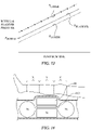
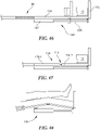
- FIGS. 42-43 application 62/667,769 One example is shown at FIGS. 42-43 application 62/667,769 , the substance of which is reproduced as FIGS. 44-45 of this application.
- deck calf segment 46 includes an extension panel 134 having a footboard 136.
- An actuator 140 illustrated as a pneumatic cylinder 142 and a piston 144, is affixed to the frame.
- the caregiver can lengthen the bed by causing the actuator to operate in a way that extends the piston, and therefore extends the extension panel as depicted by the solid lines.
- the caregiver can shorten the bed by causing the actuator to operate in a way that retracts the piston, and therefore the extension panel, as depicted in phantom.
- Footboard 136 compresses mattress 70 to accommodate the shorter length of the frame.
- FIG. 47 shows the modified version of the foot extension system.
- Extension panel 134 comprises first and second subpanels 134-1, 134-2 connected together by a hinge 148.
- the modified version of the foot extension system also includes a locking element 150.
- the illustrated locking element is a pin or a series of laterally distributed pins 150P.
- the pin is spring loaded by spring 152 into the locked position of FIG. 49 , in which position the locking element constrains the first and second subpanels to remain parallel to each other as they extend or retract, just as seen in FIG. 46 .
- the control system commands withdrawal of pin 150P from the first subpanel.
- pin 150P may be an element of a solenoid, and the instructions executed by processor 110 may cause power to be supplied to the solenoid, thereby overcoming the force exerted by spring 152 and withdrawing the pin from the first subpanel.
- control system also commands actuator 140 to operate in the retract direction. Because pin 150P no longer connects the second subpanel to the first subpanel, the subpanels can change orientation relative to each other, thereby disengaging the occupant's heel region 122 from the heel region subsection 120 of the mattress.
- the adaptations by which the control system causes mattress heel region subsection 120 and occupant heel region 122 to temporarily disengage from each other and subsequently re-engage with each other can be expressed as a method of adjusting support for a person, such as a patient, as set forth below.
- a person such as a patient
- the patient is considered to be supported in a supine lying posture throughout substantially his entire height.
- the person is considered to be lying even if one or more of the mattress sections is at a nonhorizontal orientation, such as the orientations of sections 90, 94, 96 as seen in FIG. 1 .
- the patient is considered to be supported throughout substantially his entire height even though his body shape causes certain parts of his body to not be in contact with the mattress.
- examples of such body parts include the region 160 behind the patient's achilles tendon, popliteal region 162 , arched portion 164 of his back, and arched region 166 behind his neck.
- the method includes the step of changing the angular orientation of support for the person's torso.
- the orientation change begins at a time t 0 .
- the method establishes if at least t A units of time have elapsed since t 0 . If not, the method follows "NO" path 304 from block 302 and continues to monitor the lapse of time. If so, the method follows "YES" path 306 to block 308 where the method carries out the step of withdrawing support for the person's heel region. The method then advances to block 310 where it pauses for an interval of time, for example the interval from t A to t B of FIG. 12 .
- the time interval need be no longer than the time required for the patient's stretched skin to relax to its unstretched state. Once the time interval has elapsed the method follows "YES" path 314 to block 316 . At block 316 the method re-establishes support for the patient's heel region.
- FIG. 52 is a block diagram the same as that of FIG. 51 except with a further constraint on the timing of the withdrawal of heel support at block 308.
- the additional constraint is that the withdrawal of support is deferred until at least time t 1 , the time at which the orientation change of the torso section is complete. In other words the withdrawal of support begins no sooner than the time at which the torso section orientation change is complete.
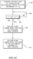
- FIG. 53 is a block diagram similar to that of FIG. 51 except that 1) block 308 spells out that the method carries out a first reconfiguration of the lower body section in order to offload the heel region of the occupant, 2) block 316 spells out that the method carries out a second reconfiguration of the lower body section 98 to reestablish loading of the heel region, and 3) pause interval block 310 of FIG. 51 is absent.
- the pause interval is inherent in FIG. 53 because the re-establishment of heel loading at block 316 cannot occur until after the offloading has occurred at block 308.
- FIG. 54 is a block diagram that bears the same relationship to FIG. 53 as FIG 52 bears to FIG. 51 . That is, the reconfiguration of the lower body section to offload the heel region is deferred until at least time t 1 , the time at which the orientation change of the torso section is complete.
- the control system includes a processor and machine readable instructions which, when executed by the processor, cause the temporary disengagement and subsequent re-engagement of the occupant's heel section and the heel region subsection of the mattress.
- the described disengagement and re-engagement are automatically triggered in response to changes in torso section orientation.
- the heel relief action can instead be carried out as an action which is not automatically triggered in response to a change in torso section orientation.
- the change in torso section orientation can be the result of a user pressing a first key on a keypad
- the heel relief action can be the result of the user pressing a second key on a keypad.
- Instructions 114 can be written to allow the orientation change and heel relief action to occur at least partly concurrently, or the heel relief action can be locked out during orientation change, even if the user presses the second button.
Landscapes
- Health & Medical Sciences (AREA)
- Nursing (AREA)
- Life Sciences & Earth Sciences (AREA)
- Animal Behavior & Ethology (AREA)
- General Health & Medical Sciences (AREA)
- Public Health (AREA)
- Veterinary Medicine (AREA)
- Invalid Beds And Related Equipment (AREA)
- Orthopedics, Nursing, And Contraception (AREA)
Claims (14)
- Eine Insassenstützstruktur zur Stützung eines Insassen, umfassend:ein ausrichtungseinstellbarer Rumpfabschnitt (90);ein Unterkörperabschnitt (96) einschließlich eines Unterabschnitts für den Fersenbereich (120), der angepasst ist, um den Fersenbereich eines Insassen der Insassenstütze zu stützen; undein Steuersystem, das angepasst ist, um:A) den Unterabschnitt für den Fersenbereich (120) zu veranlassen, sich vorübergehend im Wesentlichen vom Fersenbereich des Insassen als Reaktion auf eine Änderung der Winkelausrichtung des Rumpfabschnitts (90) zu entkoppeln, was zu einem Zeitpunkt t0 beginnt; undB) den Unterabschnitt für den Fersenbereich (120) zu veranlassen, sich im Wesentlich wieder an den Fersenbereich (120) des Insassen zu koppeln, wobei die Wiederankopplung zu einem Zeitpunkt tB stattfindet, der später ist als t0 :dadurch gekennzeichnet, dass das Steuersystem angepasst ist, um die vorübergehende wesentliche Entkopplung und die nachfolgende Wiederankopplung nur zu veranlassen, wenn sich die Winkelausrichtung des Rumpfabschnitts ändert.
- Die Insassenstützstruktur nach Anspruch 1, wobei das Steuersystem einen Prozessor (110) und maschinenlesbare Anweisungen beinhaltet, die, wenn sie vom Prozessor (110) ausgeführt werden, die vorübergehende Entkopplung und die nachfolgende Wiederankopplung veranlassen.
- Die Insassenstützstruktur nach Anspruch 1 oder Anspruch 2, wobei der Unterkörperabschnitt eine Blasenreihe kopfwärts bis zum Unterabschnitt für den Fersenbereich (120) umfasst, die aufblasbar ist, um die Entkopplung zu bewirken, und entleerbar, um die Wiederankopplung zu bewirken.
- Die Insassenstützstruktur nach Anspruch 3, wobei die Blasenreihe zwei oder mehrere in Längsrichtung verteilte Blasen (80) umfasst und das Steuersystem angepasst ist, um eine Teilmenge der Blasen (80) auszuwählen und nur die Teilmenge aufzublasen und zu entleeren, um die Entkopplung und Wiederankopplung zu bewirken.
- Die Insassenstützstruktur nach Anspruch 4, wobei die Teilmenge eine einzelne Blase ist.
- Die Insassenstützstruktur nach Anspruch 4 oder Anspruch 5, wobei das Steuersystem angepasst ist, um eine Testaufblasung der Blasen (80) zu befehlen und um in die ausgewählte Teilmenge diejenige Blase (80) einzuschließen, bei der die Testaufblasung ergibt, dass sie am geeignetsten ist, um die Kopplung zu bewirken.
- Die Insassenstützstruktur nach Anspruch 3, wobei die Blasenreihe zwei oder mehrere in Längsrichtung verteilte Blasen (80) umfasst einschließlich einer maximal kopfwärtsen Blase und einer maximal fußwärtsen Blase und das Steuersystem angepasst ist, um die Blasen nacheinander entweder beginnend mit der maximal kopfwärtsen Blase oder mit der maximal fußwärtsen Blase aufzublasen.
- Die Insassenstützstruktur nach einem der vorstehenden Ansprüche, wobei der Rumpfabschnitt (90) eine endgültige Ausrichtung zu einem Zeitpunkt t1 erreicht und die Entkopplung zu einem Zeitpunkt tA stattfindet, der nicht früher ist als der Zeitpunkt t1 .
- Die Insassenstützstruktur nach einem der vorstehenden Ansprüche, wobei der Unterkörperabschnitt (96) eine Blasenreihe in Längsrichtung zum Unterabschnitt für den Fersenbereich umfasst, die entleerbar ist, um die Entkopplung zu bewirken, und aufblasbar, um die Kopplung zu bewirken.
- Die Insassenstützstruktur nach einem der vorstehenden Ansprüche, wobei das Steuersystem angepasst ist, um die vorübergehende wesentliche Entkopplung und die nachfolgende Wiederankopplung nur zu veranlassen, wenn sich die Winkelausrichtung des Rumpfabschnitts weg von der horizontalen ändert.
- Die Insassenstützstruktur nach einem der vorstehenden Ansprüche, wobei der Unterabschnitt für den Fersenbereich (120) eine oder mehrere Blasen beinhaltet und wobei das Steuersystem angepasst ist, um:a) zu beginnen, eine der Blasen aufzublasen, um die Entkopplung zu bewirken,b) während des Aufblasens der Blase den tatsächlichen Innendruck der Blase mit mindestens einem Grenzwert zu vergleichen; undc) falls der tatsächliche Druck den Grenzwert verletzt, eine Korrekturmaßnahme zu ergreifen.
- Die Insassenstützstruktur nach einem der vorstehenden Ansprüche, wobei:A) der ausrichtungseinstellbare Rumpfabschnitt (90) und der Unterkörperabschnitt (96) Matratzenkomponenten sind; undB) die Insassenstützstruktur einen Rahmen beinhaltet, der über folgendes verfügt:1) ein ausrichtungseinstellbares Rahmenrumpfsegment (40), das die Stützung und die Ausrichtungsanpassung des ausrichtungseinstellbaren Matratzenrumpfabschnittes (90) bewirkt, und2) Ein Rahmenunterkörpersegment (46), das den Matratzenunterkörperabschnitt (96) stützt.
- Die Insassenstützstruktur nach Anspruch 12, wobei:
C) der Rahmen einen Mechanismus beinhaltet, der dazu dient, den Matratzenunterabschnitt für den Fersenbereich (120) zu veranlassen, sich vom Fersenbereich des Insassen zu entkoppeln bzw. wieder an diesen anzukoppeln. - Die Insassenstützstruktur nach Anspruch 12, wobei:
C) der Rahmen eine Verlängerungsschiene (134) beinhaltet, die dazu dient, den Matratzenunterabschnitt für den Fersenbereich (120) zu veranlassen, sich vom Fersenbereich des Insassen zu entkoppeln bzw. wieder an diesen anzukoppeln.
Applications Claiming Priority (1)
| Application Number | Priority Date | Filing Date | Title |
|---|---|---|---|
| US201862713210P | 2018-08-01 | 2018-08-01 |
Publications (2)
| Publication Number | Publication Date |
|---|---|
| EP3603598A1 EP3603598A1 (de) | 2020-02-05 |
| EP3603598B1 true EP3603598B1 (de) | 2022-09-14 |
Family
ID=67543984
Family Applications (1)
| Application Number | Title | Priority Date | Filing Date |
|---|---|---|---|
| EP19188937.7A Active EP3603598B1 (de) | 2018-08-01 | 2019-07-29 | Hautverletzungsresistente insassenstützstruktur |
Country Status (3)
| Country | Link |
|---|---|
| US (1) | US11458052B2 (de) |
| EP (1) | EP3603598B1 (de) |
| CN (1) | CN110787007B (de) |
Families Citing this family (3)
| Publication number | Priority date | Publication date | Assignee | Title |
|---|---|---|---|---|
| CN111281699B (zh) * | 2020-03-26 | 2021-06-11 | 广州恒琢科技有限公司 | 一种智能护理床 |
| US20230162587A1 (en) * | 2021-11-19 | 2023-05-25 | Hill-Rom Services, Inc. | Authorization system for integrated feature of support apparatus |
| KR20250096996A (ko) * | 2023-12-20 | 2025-06-30 | 코웨이 주식회사 | 베드 |
Family Cites Families (41)
| Publication number | Priority date | Publication date | Assignee | Title |
|---|---|---|---|---|
| US4097940A (en) | 1976-11-09 | 1978-07-04 | Hill-Rom Company, Inc. | Hospital bed having automatic contour mechanism |
| ATE81964T1 (de) * | 1985-05-10 | 1992-11-15 | Mediscus Prod Ltd | Patientenunterstuetzungsvorrichtung. |
| US4944060A (en) | 1989-03-03 | 1990-07-31 | Peery John R | Mattress assembly for the prevention and treatment of decubitus ulcers |
| US5526543A (en) | 1992-07-06 | 1996-06-18 | Nova Technologies, Inc. | Method and apparatus for treating or preventing bed sores |
| US5666681A (en) | 1995-01-03 | 1997-09-16 | Hill-Rom, Inc. | Heel pressure management apparatus and method |
| USRE43155E1 (en) * | 1995-01-03 | 2012-02-07 | Hill-Rom Services, Inc. | Hospital bed and mattress having a retractable foot section |
| AU6184398A (en) | 1997-02-24 | 1998-09-09 | Micropulse, Inc. | Mattress support system |
| US6012186A (en) | 1997-04-29 | 2000-01-11 | Hill-Rom Compnay, Inc. | Mattress articulation structure |
| EP1131035A1 (de) * | 1998-07-30 | 2001-09-12 | Medical Dynamics USA, LLC. | Vorrichtung zur fussdorsiflexion und verfahren hierzu |
| US6721980B1 (en) * | 1998-10-28 | 2004-04-20 | Hill-Fom Services, Inc. | Force optimization surface apparatus and method |
| US6370716B1 (en) | 1999-04-20 | 2002-04-16 | John W. Wilkinson | Inflatable cushioning device with tilting apparatus |
| EP1754462B1 (de) * | 1999-12-29 | 2016-07-13 | Hill-Rom Services, Inc. | Patientenliege mit Aktuatorbetätigungsglied |
| DK2140847T3 (da) | 2000-11-07 | 2012-08-27 | Tempur World Llc | Terapeutisk madrasanordning |
| US6634045B1 (en) | 2002-04-01 | 2003-10-21 | Dudonis Matt | Heel elevator support |
| NZ576473A (en) * | 2004-03-02 | 2010-07-30 | Patient Transfer Systems Inc | Patient transfer sheet with inflatable torso and head support for intubation |
| EP1847200B1 (de) * | 2004-06-04 | 2009-07-22 | Hill-Rom Services, Inc. | Matratze mit Fersendruckentlastungsteil |
| US9707141B2 (en) | 2005-07-08 | 2017-07-18 | Hill-Rom Services, Inc. | Patient support |
| US7909787B2 (en) | 2005-10-27 | 2011-03-22 | Sundaram Ravikumar | Reconfigurable heel elevator |
| EP2019911B1 (de) * | 2006-05-09 | 2015-04-01 | Hill-Rom Services, Inc. | Pulmonarmatratze |
| US20080040861A1 (en) | 2006-08-04 | 2008-02-21 | Yanin Ootayopas | Pressure sores prevention bed with adjustable head rest wherein a patient's body remains in the same position |
| US7657956B2 (en) | 2006-08-04 | 2010-02-09 | Hill-Rom Services, Inc. | Patient support |
| JP5616076B2 (ja) * | 2010-02-05 | 2014-10-29 | パラマウントベッド株式会社 | エアマットレス |
| JP5562060B2 (ja) * | 2010-02-05 | 2014-07-30 | パラマウントベッド株式会社 | エアマットレス |
| US8365330B2 (en) | 2010-02-12 | 2013-02-05 | Hill-Rom Services, Inc. | Method and apparatus for relieving shear induced by and occupant support |
| JP6192032B2 (ja) * | 2010-04-22 | 2017-09-06 | リーフ ヘルスケア インコーポレイテッド | 患者の生理学的状況をモニタリングするシステム |
| US8146187B2 (en) * | 2010-05-26 | 2012-04-03 | Hill-Rom Services, Inc. | Mattress and mattress replacement system with and intrinsic contour feature |
| US8281436B2 (en) * | 2010-07-09 | 2012-10-09 | Ehob, Inc. | Inflatable body support with dog-bone-shaped hand wells |
| US9707142B2 (en) | 2011-03-03 | 2017-07-18 | Hill-Rom Services, Inc. | Occupant support and method for positioning an occupant on the occupant support |
| US20130255699A1 (en) * | 2012-04-02 | 2013-10-03 | TurnCare, Inc. | Patient-orienting alternating pressure decubitus prevention support apparatus |
| US9358168B2 (en) | 2012-09-04 | 2016-06-07 | Hill-Rom Services, Inc. | Patient position detection for patient support surface |
| US9259098B2 (en) * | 2013-12-06 | 2016-02-16 | Hill-Rom Services, Inc. | Inflatable patient positioning unit |
| US9132051B2 (en) * | 2014-01-15 | 2015-09-15 | Hill-Rom Services, Inc. | Person support apparatuses with exercise functionalities |
| US20160016527A1 (en) * | 2014-07-21 | 2016-01-21 | Ford Global Technologies, Llc | Inflatable heel blocker |
| GB201413414D0 (en) | 2014-07-29 | 2014-09-10 | Direct Healthcare Services Ltd | Mattress |
| AU2016270661B2 (en) * | 2015-05-29 | 2021-04-22 | Hill-Rom Services, Inc. | Patient support apparatus |
| US10653247B2 (en) | 2015-11-05 | 2020-05-19 | Prs Medical Technologies, Inc. | Adjustable mattress assembly |
| EP3189823B1 (de) * | 2016-01-07 | 2020-12-16 | Hill-Rom Services, Inc. | Überwachung der lebensdauer von auflageflächen |
| WO2018035604A1 (en) | 2016-08-21 | 2018-03-01 | Mobisafe Systems Inc. | Inflatable cellular cushioning device for body support |
| CN107550655A (zh) * | 2016-11-07 | 2018-01-09 | 郑州游爱网络技术有限公司 | 一种病患独立充气锻炼康复轮椅 |
| US10363184B2 (en) * | 2017-01-03 | 2019-07-30 | Hill-Rom Services, Inc. | Patient support apparatus having urinary drainage bag lockout feature |
| JP6535356B2 (ja) * | 2017-02-06 | 2019-06-26 | パラマウントベッド株式会社 | 身体状態判定装置、身体支持装置、及び身体状態判定方法 |
-
2019
- 2019-06-27 US US16/454,445 patent/US11458052B2/en active Active
- 2019-07-12 CN CN201910631622.7A patent/CN110787007B/zh active Active
- 2019-07-29 EP EP19188937.7A patent/EP3603598B1/de active Active
Also Published As
| Publication number | Publication date |
|---|---|
| CN110787007B (zh) | 2022-09-13 |
| CN110787007A (zh) | 2020-02-14 |
| EP3603598A1 (de) | 2020-02-05 |
| US11458052B2 (en) | 2022-10-04 |
| US20200038269A1 (en) | 2020-02-06 |
Similar Documents
| Publication | Publication Date | Title |
|---|---|---|
| US10617581B2 (en) | Occupant support with longitudinally spaced turn assist members, associated graphical user interface, and methods of providing access to portions of the occupant support or to occupants thereof | |
| US6370716B1 (en) | Inflatable cushioning device with tilting apparatus | |
| EP3603598B1 (de) | Hautverletzungsresistente insassenstützstruktur | |
| JP5694802B2 (ja) | 占有者支持体により誘発される剪断を緩和する方法および装置 | |
| EP2462912B1 (de) | Matratzenblasenerhöhung während des Aufstehens aus der Sitzposition | |
| US12377004B2 (en) | Patient support systems with a chair configuration and a stowable foot section | |
| US5815862A (en) | Portable orthopedic bed | |
| US10413464B2 (en) | Multi-mode sacral unloading pressure relief in a patient support surface | |
| US20170224565A1 (en) | Method for Positioning an Occupant on the Occupant Support | |
| US20080077059A1 (en) | Massage Machine | |
| US20130000041A1 (en) | Occupant Support with a Cyclically Variable Profile | |
| EP2189140B1 (de) | Anhebungsfunktion für ein Bett | |
| JP2013528100A (ja) | 使用者の体型に合わせて回転軸が可変な床ずれ防止用電動ベッドプラットフォームおよびその姿勢変更周期の制御方法 | |
| US20150143629A1 (en) | Footboard having integrated foot cushion | |
| US20060016016A1 (en) | Modular bed system | |
| US8146187B2 (en) | Mattress and mattress replacement system with and intrinsic contour feature | |
| KR101841223B1 (ko) | 목과 척추의 스트레칭 견인을 이용한 기능성 신체 교정장치 | |
| JP4851861B2 (ja) | 施療機 | |
| AU2010251758B2 (en) | An inflatable cell system | |
| US11998497B2 (en) | Device for supporting a body part | |
| WO2026058151A1 (en) | Foldable patient support surface | |
| GB2387114A (en) | Patient support structures | |
| CA2202222A1 (en) | Portable orthopedic bed |
Legal Events
| Date | Code | Title | Description |
|---|---|---|---|
| PUAI | Public reference made under article 153(3) epc to a published international application that has entered the european phase |
Free format text: ORIGINAL CODE: 0009012 |
|
| STAA | Information on the status of an ep patent application or granted ep patent |
Free format text: STATUS: THE APPLICATION HAS BEEN PUBLISHED |
|
| AK | Designated contracting states |
Kind code of ref document: A1 Designated state(s): AL AT BE BG CH CY CZ DE DK EE ES FI FR GB GR HR HU IE IS IT LI LT LU LV MC MK MT NL NO PL PT RO RS SE SI SK SM TR |
|
| AX | Request for extension of the european patent |
Extension state: BA ME |
|
| STAA | Information on the status of an ep patent application or granted ep patent |
Free format text: STATUS: REQUEST FOR EXAMINATION WAS MADE |
|
| 17P | Request for examination filed |
Effective date: 20200803 |
|
| RBV | Designated contracting states (corrected) |
Designated state(s): AL AT BE BG CH CY CZ DE DK EE ES FI FR GB GR HR HU IE IS IT LI LT LU LV MC MK MT NL NO PL PT RO RS SE SI SK SM TR |
|
| GRAP | Despatch of communication of intention to grant a patent |
Free format text: ORIGINAL CODE: EPIDOSNIGR1 |
|
| STAA | Information on the status of an ep patent application or granted ep patent |
Free format text: STATUS: GRANT OF PATENT IS INTENDED |
|
| INTG | Intention to grant announced |
Effective date: 20220420 |
|
| GRAS | Grant fee paid |
Free format text: ORIGINAL CODE: EPIDOSNIGR3 |
|
| GRAA | (expected) grant |
Free format text: ORIGINAL CODE: 0009210 |
|
| STAA | Information on the status of an ep patent application or granted ep patent |
Free format text: STATUS: THE PATENT HAS BEEN GRANTED |
|
| AK | Designated contracting states |
Kind code of ref document: B1 Designated state(s): AL AT BE BG CH CY CZ DE DK EE ES FI FR GB GR HR HU IE IS IT LI LT LU LV MC MK MT NL NO PL PT RO RS SE SI SK SM TR |
|
| REG | Reference to a national code |
Ref country code: GB Ref legal event code: FG4D |
|
| REG | Reference to a national code |
Ref country code: CH Ref legal event code: EP |
|
| REG | Reference to a national code |
Ref country code: DE Ref legal event code: R096 Ref document number: 602019019510 Country of ref document: DE |
|
| REG | Reference to a national code |
Ref country code: IE Ref legal event code: FG4D |
|
| REG | Reference to a national code |
Ref country code: AT Ref legal event code: REF Ref document number: 1518283 Country of ref document: AT Kind code of ref document: T Effective date: 20221015 |
|
| REG | Reference to a national code |
Ref country code: LT Ref legal event code: MG9D |
|
| REG | Reference to a national code |
Ref country code: NL Ref legal event code: MP Effective date: 20220914 |
|
| PG25 | Lapsed in a contracting state [announced via postgrant information from national office to epo] |
Ref country code: SE Free format text: LAPSE BECAUSE OF FAILURE TO SUBMIT A TRANSLATION OF THE DESCRIPTION OR TO PAY THE FEE WITHIN THE PRESCRIBED TIME-LIMIT Effective date: 20220914 Ref country code: RS Free format text: LAPSE BECAUSE OF FAILURE TO SUBMIT A TRANSLATION OF THE DESCRIPTION OR TO PAY THE FEE WITHIN THE PRESCRIBED TIME-LIMIT Effective date: 20220914 Ref country code: NO Free format text: LAPSE BECAUSE OF FAILURE TO SUBMIT A TRANSLATION OF THE DESCRIPTION OR TO PAY THE FEE WITHIN THE PRESCRIBED TIME-LIMIT Effective date: 20221214 Ref country code: LV Free format text: LAPSE BECAUSE OF FAILURE TO SUBMIT A TRANSLATION OF THE DESCRIPTION OR TO PAY THE FEE WITHIN THE PRESCRIBED TIME-LIMIT Effective date: 20220914 Ref country code: LT Free format text: LAPSE BECAUSE OF FAILURE TO SUBMIT A TRANSLATION OF THE DESCRIPTION OR TO PAY THE FEE WITHIN THE PRESCRIBED TIME-LIMIT Effective date: 20220914 Ref country code: FI Free format text: LAPSE BECAUSE OF FAILURE TO SUBMIT A TRANSLATION OF THE DESCRIPTION OR TO PAY THE FEE WITHIN THE PRESCRIBED TIME-LIMIT Effective date: 20220914 |
|
| REG | Reference to a national code |
Ref country code: AT Ref legal event code: MK05 Ref document number: 1518283 Country of ref document: AT Kind code of ref document: T Effective date: 20220914 |
|
| PG25 | Lapsed in a contracting state [announced via postgrant information from national office to epo] |
Ref country code: HR Free format text: LAPSE BECAUSE OF FAILURE TO SUBMIT A TRANSLATION OF THE DESCRIPTION OR TO PAY THE FEE WITHIN THE PRESCRIBED TIME-LIMIT Effective date: 20220914 Ref country code: GR Free format text: LAPSE BECAUSE OF FAILURE TO SUBMIT A TRANSLATION OF THE DESCRIPTION OR TO PAY THE FEE WITHIN THE PRESCRIBED TIME-LIMIT Effective date: 20221215 |
|
| PG25 | Lapsed in a contracting state [announced via postgrant information from national office to epo] |
Ref country code: SM Free format text: LAPSE BECAUSE OF FAILURE TO SUBMIT A TRANSLATION OF THE DESCRIPTION OR TO PAY THE FEE WITHIN THE PRESCRIBED TIME-LIMIT Effective date: 20220914 Ref country code: RO Free format text: LAPSE BECAUSE OF FAILURE TO SUBMIT A TRANSLATION OF THE DESCRIPTION OR TO PAY THE FEE WITHIN THE PRESCRIBED TIME-LIMIT Effective date: 20220914 Ref country code: PT Free format text: LAPSE BECAUSE OF FAILURE TO SUBMIT A TRANSLATION OF THE DESCRIPTION OR TO PAY THE FEE WITHIN THE PRESCRIBED TIME-LIMIT Effective date: 20230116 Ref country code: ES Free format text: LAPSE BECAUSE OF FAILURE TO SUBMIT A TRANSLATION OF THE DESCRIPTION OR TO PAY THE FEE WITHIN THE PRESCRIBED TIME-LIMIT Effective date: 20220914 Ref country code: CZ Free format text: LAPSE BECAUSE OF FAILURE TO SUBMIT A TRANSLATION OF THE DESCRIPTION OR TO PAY THE FEE WITHIN THE PRESCRIBED TIME-LIMIT Effective date: 20220914 Ref country code: AT Free format text: LAPSE BECAUSE OF FAILURE TO SUBMIT A TRANSLATION OF THE DESCRIPTION OR TO PAY THE FEE WITHIN THE PRESCRIBED TIME-LIMIT Effective date: 20220914 |
|
| PG25 | Lapsed in a contracting state [announced via postgrant information from national office to epo] |
Ref country code: SK Free format text: LAPSE BECAUSE OF FAILURE TO SUBMIT A TRANSLATION OF THE DESCRIPTION OR TO PAY THE FEE WITHIN THE PRESCRIBED TIME-LIMIT Effective date: 20220914 Ref country code: PL Free format text: LAPSE BECAUSE OF FAILURE TO SUBMIT A TRANSLATION OF THE DESCRIPTION OR TO PAY THE FEE WITHIN THE PRESCRIBED TIME-LIMIT Effective date: 20220914 Ref country code: IS Free format text: LAPSE BECAUSE OF FAILURE TO SUBMIT A TRANSLATION OF THE DESCRIPTION OR TO PAY THE FEE WITHIN THE PRESCRIBED TIME-LIMIT Effective date: 20230114 Ref country code: EE Free format text: LAPSE BECAUSE OF FAILURE TO SUBMIT A TRANSLATION OF THE DESCRIPTION OR TO PAY THE FEE WITHIN THE PRESCRIBED TIME-LIMIT Effective date: 20220914 |
|
| REG | Reference to a national code |
Ref country code: DE Ref legal event code: R097 Ref document number: 602019019510 Country of ref document: DE |
|
| PG25 | Lapsed in a contracting state [announced via postgrant information from national office to epo] |
Ref country code: NL Free format text: LAPSE BECAUSE OF FAILURE TO SUBMIT A TRANSLATION OF THE DESCRIPTION OR TO PAY THE FEE WITHIN THE PRESCRIBED TIME-LIMIT Effective date: 20220914 Ref country code: AL Free format text: LAPSE BECAUSE OF FAILURE TO SUBMIT A TRANSLATION OF THE DESCRIPTION OR TO PAY THE FEE WITHIN THE PRESCRIBED TIME-LIMIT Effective date: 20220914 |
|
| PLBE | No opposition filed within time limit |
Free format text: ORIGINAL CODE: 0009261 |
|
| STAA | Information on the status of an ep patent application or granted ep patent |
Free format text: STATUS: NO OPPOSITION FILED WITHIN TIME LIMIT |
|
| PG25 | Lapsed in a contracting state [announced via postgrant information from national office to epo] |
Ref country code: DK Free format text: LAPSE BECAUSE OF FAILURE TO SUBMIT A TRANSLATION OF THE DESCRIPTION OR TO PAY THE FEE WITHIN THE PRESCRIBED TIME-LIMIT Effective date: 20220914 |
|
| 26N | No opposition filed |
Effective date: 20230615 |
|
| PG25 | Lapsed in a contracting state [announced via postgrant information from national office to epo] |
Ref country code: SI Free format text: LAPSE BECAUSE OF FAILURE TO SUBMIT A TRANSLATION OF THE DESCRIPTION OR TO PAY THE FEE WITHIN THE PRESCRIBED TIME-LIMIT Effective date: 20220914 |
|
| PG25 | Lapsed in a contracting state [announced via postgrant information from national office to epo] |
Ref country code: MC Free format text: LAPSE BECAUSE OF FAILURE TO SUBMIT A TRANSLATION OF THE DESCRIPTION OR TO PAY THE FEE WITHIN THE PRESCRIBED TIME-LIMIT Effective date: 20220914 |
|
| PG25 | Lapsed in a contracting state [announced via postgrant information from national office to epo] |
Ref country code: MC Free format text: LAPSE BECAUSE OF FAILURE TO SUBMIT A TRANSLATION OF THE DESCRIPTION OR TO PAY THE FEE WITHIN THE PRESCRIBED TIME-LIMIT Effective date: 20220914 |
|
| REG | Reference to a national code |
Ref country code: CH Ref legal event code: PL |
|
| REG | Reference to a national code |
Ref country code: BE Ref legal event code: MM Effective date: 20230731 |
|
| PG25 | Lapsed in a contracting state [announced via postgrant information from national office to epo] |
Ref country code: LU Free format text: LAPSE BECAUSE OF NON-PAYMENT OF DUE FEES Effective date: 20230729 |
|
| PG25 | Lapsed in a contracting state [announced via postgrant information from national office to epo] |
Ref country code: LU Free format text: LAPSE BECAUSE OF NON-PAYMENT OF DUE FEES Effective date: 20230729 |
|
| REG | Reference to a national code |
Ref country code: IE Ref legal event code: MM4A |
|
| PG25 | Lapsed in a contracting state [announced via postgrant information from national office to epo] |
Ref country code: CH Free format text: LAPSE BECAUSE OF NON-PAYMENT OF DUE FEES Effective date: 20230731 |
|
| PG25 | Lapsed in a contracting state [announced via postgrant information from national office to epo] |
Ref country code: IT Free format text: LAPSE BECAUSE OF FAILURE TO SUBMIT A TRANSLATION OF THE DESCRIPTION OR TO PAY THE FEE WITHIN THE PRESCRIBED TIME-LIMIT Effective date: 20220914 Ref country code: BE Free format text: LAPSE BECAUSE OF NON-PAYMENT OF DUE FEES Effective date: 20230731 |
|
| PG25 | Lapsed in a contracting state [announced via postgrant information from national office to epo] |
Ref country code: IE Free format text: LAPSE BECAUSE OF NON-PAYMENT OF DUE FEES Effective date: 20230729 |
|
| PG25 | Lapsed in a contracting state [announced via postgrant information from national office to epo] |
Ref country code: IE Free format text: LAPSE BECAUSE OF NON-PAYMENT OF DUE FEES Effective date: 20230729 |
|
| PG25 | Lapsed in a contracting state [announced via postgrant information from national office to epo] |
Ref country code: BG Free format text: LAPSE BECAUSE OF FAILURE TO SUBMIT A TRANSLATION OF THE DESCRIPTION OR TO PAY THE FEE WITHIN THE PRESCRIBED TIME-LIMIT Effective date: 20220914 |
|
| PG25 | Lapsed in a contracting state [announced via postgrant information from national office to epo] |
Ref country code: BG Free format text: LAPSE BECAUSE OF FAILURE TO SUBMIT A TRANSLATION OF THE DESCRIPTION OR TO PAY THE FEE WITHIN THE PRESCRIBED TIME-LIMIT Effective date: 20220914 |
|
| PGFP | Annual fee paid to national office [announced via postgrant information from national office to epo] |
Ref country code: GB Payment date: 20250619 Year of fee payment: 7 |
|
| PGFP | Annual fee paid to national office [announced via postgrant information from national office to epo] |
Ref country code: FR Payment date: 20250619 Year of fee payment: 7 |
|
| PG25 | Lapsed in a contracting state [announced via postgrant information from national office to epo] |
Ref country code: CY Free format text: LAPSE BECAUSE OF FAILURE TO SUBMIT A TRANSLATION OF THE DESCRIPTION OR TO PAY THE FEE WITHIN THE PRESCRIBED TIME-LIMIT; INVALID AB INITIO Effective date: 20190729 |
|
| PG25 | Lapsed in a contracting state [announced via postgrant information from national office to epo] |
Ref country code: HU Free format text: LAPSE BECAUSE OF FAILURE TO SUBMIT A TRANSLATION OF THE DESCRIPTION OR TO PAY THE FEE WITHIN THE PRESCRIBED TIME-LIMIT; INVALID AB INITIO Effective date: 20190729 |
|
| PGFP | Annual fee paid to national office [announced via postgrant information from national office to epo] |
Ref country code: DE Payment date: 20250620 Year of fee payment: 7 |
|
| PG25 | Lapsed in a contracting state [announced via postgrant information from national office to epo] |
Ref country code: TR Free format text: LAPSE BECAUSE OF FAILURE TO SUBMIT A TRANSLATION OF THE DESCRIPTION OR TO PAY THE FEE WITHIN THE PRESCRIBED TIME-LIMIT Effective date: 20220914 |