EP3604020A1 - Kombinierte steuerung von zwei spannungsquellen - Google Patents
Kombinierte steuerung von zwei spannungsquellen Download PDFInfo
- Publication number
- EP3604020A1 EP3604020A1 EP19197685.1A EP19197685A EP3604020A1 EP 3604020 A1 EP3604020 A1 EP 3604020A1 EP 19197685 A EP19197685 A EP 19197685A EP 3604020 A1 EP3604020 A1 EP 3604020A1
- Authority
- EP
- European Patent Office
- Prior art keywords
- voltage source
- voltage
- management system
- battery
- load
- Prior art date
- Legal status (The legal status is an assumption and is not a legal conclusion. Google has not performed a legal analysis and makes no representation as to the accuracy of the status listed.)
- Granted
Links
Images







Classifications
-
- H—ELECTRICITY
- H02—GENERATION; CONVERSION OR DISTRIBUTION OF ELECTRIC POWER
- H02J—ELECTRIC POWER NETWORKS; CIRCUIT ARRANGEMENTS OR SYSTEMS FOR SUPPLYING OR DISTRIBUTING ELECTRIC POWER; SYSTEMS FOR STORING ELECTRIC ENERGY
- H02J1/00—Circuit arrangements for DC mains or DC distribution networks
- H02J1/06—Two-wire DC power distribution systems
-
- B—PERFORMING OPERATIONS; TRANSPORTING
- B60—VEHICLES IN GENERAL
- B60L—PROPULSION OF ELECTRICALLY-PROPELLED VEHICLES; SUPPLYING ELECTRIC POWER FOR AUXILIARY EQUIPMENT OF ELECTRICALLY-PROPELLED VEHICLES; ELECTRODYNAMIC BRAKE SYSTEMS FOR VEHICLES IN GENERAL; MAGNETIC SUSPENSION OR LEVITATION FOR VEHICLES; MONITORING OPERATING VARIABLES OF ELECTRICALLY-PROPELLED VEHICLES; ELECTRIC SAFETY DEVICES FOR ELECTRICALLY-PROPELLED VEHICLES
- B60L3/00—Electric devices on electrically-propelled vehicles for safety purposes; Monitoring operating variables, e.g. speed, deceleration or energy consumption
- B60L3/0023—Detecting, eliminating, remedying or compensating for drive train abnormalities, e.g. failures within the drive train
- B60L3/0046—Detecting, eliminating, remedying or compensating for drive train abnormalities, e.g. failures within the drive train relating to electric energy storage systems, e.g. batteries or capacitors
-
- B—PERFORMING OPERATIONS; TRANSPORTING
- B60—VEHICLES IN GENERAL
- B60L—PROPULSION OF ELECTRICALLY-PROPELLED VEHICLES; SUPPLYING ELECTRIC POWER FOR AUXILIARY EQUIPMENT OF ELECTRICALLY-PROPELLED VEHICLES; ELECTRODYNAMIC BRAKE SYSTEMS FOR VEHICLES IN GENERAL; MAGNETIC SUSPENSION OR LEVITATION FOR VEHICLES; MONITORING OPERATING VARIABLES OF ELECTRICALLY-PROPELLED VEHICLES; ELECTRIC SAFETY DEVICES FOR ELECTRICALLY-PROPELLED VEHICLES
- B60L50/00—Electric propulsion with power supplied within the vehicle
- B60L50/50—Electric propulsion with power supplied within the vehicle using propulsion power supplied by batteries or fuel cells
- B60L50/51—Electric propulsion with power supplied within the vehicle using propulsion power supplied by batteries or fuel cells characterised by AC-motors
-
- B—PERFORMING OPERATIONS; TRANSPORTING
- B60—VEHICLES IN GENERAL
- B60L—PROPULSION OF ELECTRICALLY-PROPELLED VEHICLES; SUPPLYING ELECTRIC POWER FOR AUXILIARY EQUIPMENT OF ELECTRICALLY-PROPELLED VEHICLES; ELECTRODYNAMIC BRAKE SYSTEMS FOR VEHICLES IN GENERAL; MAGNETIC SUSPENSION OR LEVITATION FOR VEHICLES; MONITORING OPERATING VARIABLES OF ELECTRICALLY-PROPELLED VEHICLES; ELECTRIC SAFETY DEVICES FOR ELECTRICALLY-PROPELLED VEHICLES
- B60L50/00—Electric propulsion with power supplied within the vehicle
- B60L50/50—Electric propulsion with power supplied within the vehicle using propulsion power supplied by batteries or fuel cells
- B60L50/60—Electric propulsion with power supplied within the vehicle using propulsion power supplied by batteries or fuel cells using power supplied by batteries
- B60L50/61—Electric propulsion with power supplied within the vehicle using propulsion power supplied by batteries or fuel cells using power supplied by batteries by batteries charged by engine-driven generators, e.g. series hybrid electric vehicles
- B60L50/62—Electric propulsion with power supplied within the vehicle using propulsion power supplied by batteries or fuel cells using power supplied by batteries by batteries charged by engine-driven generators, e.g. series hybrid electric vehicles charged by low-power generators primarily intended to support the batteries, e.g. range extenders
-
- B—PERFORMING OPERATIONS; TRANSPORTING
- B60—VEHICLES IN GENERAL
- B60L—PROPULSION OF ELECTRICALLY-PROPELLED VEHICLES; SUPPLYING ELECTRIC POWER FOR AUXILIARY EQUIPMENT OF ELECTRICALLY-PROPELLED VEHICLES; ELECTRODYNAMIC BRAKE SYSTEMS FOR VEHICLES IN GENERAL; MAGNETIC SUSPENSION OR LEVITATION FOR VEHICLES; MONITORING OPERATING VARIABLES OF ELECTRICALLY-PROPELLED VEHICLES; ELECTRIC SAFETY DEVICES FOR ELECTRICALLY-PROPELLED VEHICLES
- B60L58/00—Methods or circuit arrangements for monitoring or controlling batteries or fuel cells, specially adapted for electric vehicles
- B60L58/10—Methods or circuit arrangements for monitoring or controlling batteries or fuel cells, specially adapted for electric vehicles for monitoring or controlling batteries
-
- B—PERFORMING OPERATIONS; TRANSPORTING
- B60—VEHICLES IN GENERAL
- B60L—PROPULSION OF ELECTRICALLY-PROPELLED VEHICLES; SUPPLYING ELECTRIC POWER FOR AUXILIARY EQUIPMENT OF ELECTRICALLY-PROPELLED VEHICLES; ELECTRODYNAMIC BRAKE SYSTEMS FOR VEHICLES IN GENERAL; MAGNETIC SUSPENSION OR LEVITATION FOR VEHICLES; MONITORING OPERATING VARIABLES OF ELECTRICALLY-PROPELLED VEHICLES; ELECTRIC SAFETY DEVICES FOR ELECTRICALLY-PROPELLED VEHICLES
- B60L58/00—Methods or circuit arrangements for monitoring or controlling batteries or fuel cells, specially adapted for electric vehicles
- B60L58/10—Methods or circuit arrangements for monitoring or controlling batteries or fuel cells, specially adapted for electric vehicles for monitoring or controlling batteries
- B60L58/18—Methods or circuit arrangements for monitoring or controlling batteries or fuel cells, specially adapted for electric vehicles for monitoring or controlling batteries of two or more battery modules
- B60L58/20—Methods or circuit arrangements for monitoring or controlling batteries or fuel cells, specially adapted for electric vehicles for monitoring or controlling batteries of two or more battery modules having different nominal voltages
-
- B—PERFORMING OPERATIONS; TRANSPORTING
- B60—VEHICLES IN GENERAL
- B60L—PROPULSION OF ELECTRICALLY-PROPELLED VEHICLES; SUPPLYING ELECTRIC POWER FOR AUXILIARY EQUIPMENT OF ELECTRICALLY-PROPELLED VEHICLES; ELECTRODYNAMIC BRAKE SYSTEMS FOR VEHICLES IN GENERAL; MAGNETIC SUSPENSION OR LEVITATION FOR VEHICLES; MONITORING OPERATING VARIABLES OF ELECTRICALLY-PROPELLED VEHICLES; ELECTRIC SAFETY DEVICES FOR ELECTRICALLY-PROPELLED VEHICLES
- B60L58/00—Methods or circuit arrangements for monitoring or controlling batteries or fuel cells, specially adapted for electric vehicles
- B60L58/10—Methods or circuit arrangements for monitoring or controlling batteries or fuel cells, specially adapted for electric vehicles for monitoring or controlling batteries
- B60L58/18—Methods or circuit arrangements for monitoring or controlling batteries or fuel cells, specially adapted for electric vehicles for monitoring or controlling batteries of two or more battery modules
- B60L58/22—Balancing the charge of battery modules
-
- B—PERFORMING OPERATIONS; TRANSPORTING
- B60—VEHICLES IN GENERAL
- B60L—PROPULSION OF ELECTRICALLY-PROPELLED VEHICLES; SUPPLYING ELECTRIC POWER FOR AUXILIARY EQUIPMENT OF ELECTRICALLY-PROPELLED VEHICLES; ELECTRODYNAMIC BRAKE SYSTEMS FOR VEHICLES IN GENERAL; MAGNETIC SUSPENSION OR LEVITATION FOR VEHICLES; MONITORING OPERATING VARIABLES OF ELECTRICALLY-PROPELLED VEHICLES; ELECTRIC SAFETY DEVICES FOR ELECTRICALLY-PROPELLED VEHICLES
- B60L58/00—Methods or circuit arrangements for monitoring or controlling batteries or fuel cells, specially adapted for electric vehicles
- B60L58/40—Methods or circuit arrangements for monitoring or controlling batteries or fuel cells, specially adapted for electric vehicles for controlling a combination of batteries and fuel cells
-
- H—ELECTRICITY
- H02—GENERATION; CONVERSION OR DISTRIBUTION OF ELECTRIC POWER
- H02J—ELECTRIC POWER NETWORKS; CIRCUIT ARRANGEMENTS OR SYSTEMS FOR SUPPLYING OR DISTRIBUTING ELECTRIC POWER; SYSTEMS FOR STORING ELECTRIC ENERGY
- H02J7/00—Circuit arrangements for charging or discharging batteries or for supplying loads from batteries
- H02J7/14—Circuit arrangements for charging or discharging batteries or for supplying loads from batteries for charging batteries from dynamo-electric generators driven at varying speed, e.g. on vehicle
- H02J7/1423—Circuit arrangements for charging or discharging batteries or for supplying loads from batteries for charging batteries from dynamo-electric generators driven at varying speed, e.g. on vehicle with multiple batteries
-
- H—ELECTRICITY
- H02—GENERATION; CONVERSION OR DISTRIBUTION OF ELECTRIC POWER
- H02J—ELECTRIC POWER NETWORKS; CIRCUIT ARRANGEMENTS OR SYSTEMS FOR SUPPLYING OR DISTRIBUTING ELECTRIC POWER; SYSTEMS FOR STORING ELECTRIC ENERGY
- H02J7/00—Circuit arrangements for charging or discharging batteries or for supplying loads from batteries
- H02J7/34—Parallel operation in networks using both storage and other DC sources, e.g. providing buffering
- H02J7/342—The other DC source being a battery actively interacting with the first one, i.e. battery to battery charging
-
- H—ELECTRICITY
- H02—GENERATION; CONVERSION OR DISTRIBUTION OF ELECTRIC POWER
- H02J—ELECTRIC POWER NETWORKS; CIRCUIT ARRANGEMENTS OR SYSTEMS FOR SUPPLYING OR DISTRIBUTING ELECTRIC POWER; SYSTEMS FOR STORING ELECTRIC ENERGY
- H02J7/00—Circuit arrangements for charging or discharging batteries or for supplying loads from batteries
- H02J7/865—Battery or charger load switching, e.g. concurrent charging and load supply
-
- B—PERFORMING OPERATIONS; TRANSPORTING
- B60—VEHICLES IN GENERAL
- B60L—PROPULSION OF ELECTRICALLY-PROPELLED VEHICLES; SUPPLYING ELECTRIC POWER FOR AUXILIARY EQUIPMENT OF ELECTRICALLY-PROPELLED VEHICLES; ELECTRODYNAMIC BRAKE SYSTEMS FOR VEHICLES IN GENERAL; MAGNETIC SUSPENSION OR LEVITATION FOR VEHICLES; MONITORING OPERATING VARIABLES OF ELECTRICALLY-PROPELLED VEHICLES; ELECTRIC SAFETY DEVICES FOR ELECTRICALLY-PROPELLED VEHICLES
- B60L2210/00—Converter types
- B60L2210/10—DC to DC converters
-
- B—PERFORMING OPERATIONS; TRANSPORTING
- B60—VEHICLES IN GENERAL
- B60L—PROPULSION OF ELECTRICALLY-PROPELLED VEHICLES; SUPPLYING ELECTRIC POWER FOR AUXILIARY EQUIPMENT OF ELECTRICALLY-PROPELLED VEHICLES; ELECTRODYNAMIC BRAKE SYSTEMS FOR VEHICLES IN GENERAL; MAGNETIC SUSPENSION OR LEVITATION FOR VEHICLES; MONITORING OPERATING VARIABLES OF ELECTRICALLY-PROPELLED VEHICLES; ELECTRIC SAFETY DEVICES FOR ELECTRICALLY-PROPELLED VEHICLES
- B60L2240/00—Control parameters of input or output; Target parameters
- B60L2240/40—Drive Train control parameters
- B60L2240/54—Drive Train control parameters related to batteries
- B60L2240/545—Temperature
-
- H—ELECTRICITY
- H02—GENERATION; CONVERSION OR DISTRIBUTION OF ELECTRIC POWER
- H02J—ELECTRIC POWER NETWORKS; CIRCUIT ARRANGEMENTS OR SYSTEMS FOR SUPPLYING OR DISTRIBUTING ELECTRIC POWER; SYSTEMS FOR STORING ELECTRIC ENERGY
- H02J1/00—Circuit arrangements for DC mains or DC distribution networks
- H02J1/08—Three-wire DC power distribution systems; Systems having more than three wires
- H02J1/082—DC supplies with two or more different DC voltage levels
-
- Y—GENERAL TAGGING OF NEW TECHNOLOGICAL DEVELOPMENTS; GENERAL TAGGING OF CROSS-SECTIONAL TECHNOLOGIES SPANNING OVER SEVERAL SECTIONS OF THE IPC; TECHNICAL SUBJECTS COVERED BY FORMER USPC CROSS-REFERENCE ART COLLECTIONS [XRACs] AND DIGESTS
- Y02—TECHNOLOGIES OR APPLICATIONS FOR MITIGATION OR ADAPTATION AGAINST CLIMATE CHANGE
- Y02T—CLIMATE CHANGE MITIGATION TECHNOLOGIES RELATED TO TRANSPORTATION
- Y02T10/00—Road transport of goods or passengers
- Y02T10/60—Other road transportation technologies with climate change mitigation effect
- Y02T10/62—Hybrid vehicles
-
- Y—GENERAL TAGGING OF NEW TECHNOLOGICAL DEVELOPMENTS; GENERAL TAGGING OF CROSS-SECTIONAL TECHNOLOGIES SPANNING OVER SEVERAL SECTIONS OF THE IPC; TECHNICAL SUBJECTS COVERED BY FORMER USPC CROSS-REFERENCE ART COLLECTIONS [XRACs] AND DIGESTS
- Y02—TECHNOLOGIES OR APPLICATIONS FOR MITIGATION OR ADAPTATION AGAINST CLIMATE CHANGE
- Y02T—CLIMATE CHANGE MITIGATION TECHNOLOGIES RELATED TO TRANSPORTATION
- Y02T10/00—Road transport of goods or passengers
- Y02T10/60—Other road transportation technologies with climate change mitigation effect
- Y02T10/70—Energy storage systems for electromobility, e.g. batteries
-
- Y—GENERAL TAGGING OF NEW TECHNOLOGICAL DEVELOPMENTS; GENERAL TAGGING OF CROSS-SECTIONAL TECHNOLOGIES SPANNING OVER SEVERAL SECTIONS OF THE IPC; TECHNICAL SUBJECTS COVERED BY FORMER USPC CROSS-REFERENCE ART COLLECTIONS [XRACs] AND DIGESTS
- Y02—TECHNOLOGIES OR APPLICATIONS FOR MITIGATION OR ADAPTATION AGAINST CLIMATE CHANGE
- Y02T—CLIMATE CHANGE MITIGATION TECHNOLOGIES RELATED TO TRANSPORTATION
- Y02T10/00—Road transport of goods or passengers
- Y02T10/60—Other road transportation technologies with climate change mitigation effect
- Y02T10/7072—Electromobility specific charging systems or methods for batteries, ultracapacitors, supercapacitors or double-layer capacitors
-
- Y—GENERAL TAGGING OF NEW TECHNOLOGICAL DEVELOPMENTS; GENERAL TAGGING OF CROSS-SECTIONAL TECHNOLOGIES SPANNING OVER SEVERAL SECTIONS OF THE IPC; TECHNICAL SUBJECTS COVERED BY FORMER USPC CROSS-REFERENCE ART COLLECTIONS [XRACs] AND DIGESTS
- Y02—TECHNOLOGIES OR APPLICATIONS FOR MITIGATION OR ADAPTATION AGAINST CLIMATE CHANGE
- Y02T—CLIMATE CHANGE MITIGATION TECHNOLOGIES RELATED TO TRANSPORTATION
- Y02T10/00—Road transport of goods or passengers
- Y02T10/60—Other road transportation technologies with climate change mitigation effect
- Y02T10/72—Electric energy management in electromobility
-
- Y—GENERAL TAGGING OF NEW TECHNOLOGICAL DEVELOPMENTS; GENERAL TAGGING OF CROSS-SECTIONAL TECHNOLOGIES SPANNING OVER SEVERAL SECTIONS OF THE IPC; TECHNICAL SUBJECTS COVERED BY FORMER USPC CROSS-REFERENCE ART COLLECTIONS [XRACs] AND DIGESTS
- Y02—TECHNOLOGIES OR APPLICATIONS FOR MITIGATION OR ADAPTATION AGAINST CLIMATE CHANGE
- Y02T—CLIMATE CHANGE MITIGATION TECHNOLOGIES RELATED TO TRANSPORTATION
- Y02T90/00—Enabling technologies or technologies with a potential or indirect contribution to GHG emissions mitigation
- Y02T90/10—Technologies relating to charging of electric vehicles
- Y02T90/12—Electric charging stations
-
- Y—GENERAL TAGGING OF NEW TECHNOLOGICAL DEVELOPMENTS; GENERAL TAGGING OF CROSS-SECTIONAL TECHNOLOGIES SPANNING OVER SEVERAL SECTIONS OF THE IPC; TECHNICAL SUBJECTS COVERED BY FORMER USPC CROSS-REFERENCE ART COLLECTIONS [XRACs] AND DIGESTS
- Y02—TECHNOLOGIES OR APPLICATIONS FOR MITIGATION OR ADAPTATION AGAINST CLIMATE CHANGE
- Y02T—CLIMATE CHANGE MITIGATION TECHNOLOGIES RELATED TO TRANSPORTATION
- Y02T90/00—Enabling technologies or technologies with a potential or indirect contribution to GHG emissions mitigation
- Y02T90/10—Technologies relating to charging of electric vehicles
- Y02T90/14—Plug-in electric vehicles
-
- Y—GENERAL TAGGING OF NEW TECHNOLOGICAL DEVELOPMENTS; GENERAL TAGGING OF CROSS-SECTIONAL TECHNOLOGIES SPANNING OVER SEVERAL SECTIONS OF THE IPC; TECHNICAL SUBJECTS COVERED BY FORMER USPC CROSS-REFERENCE ART COLLECTIONS [XRACs] AND DIGESTS
- Y02—TECHNOLOGIES OR APPLICATIONS FOR MITIGATION OR ADAPTATION AGAINST CLIMATE CHANGE
- Y02T—CLIMATE CHANGE MITIGATION TECHNOLOGIES RELATED TO TRANSPORTATION
- Y02T90/00—Enabling technologies or technologies with a potential or indirect contribution to GHG emissions mitigation
- Y02T90/40—Application of hydrogen technology to transportation, e.g. using fuel cells
Definitions
- the invention relates to an electrical management system comprising two voltage sources of different voltage levels, low and high, particularly suitable for a motor vehicle. It also relates to a system such as a motor vehicle as such comprising such an electrical management system. Finally, it also relates to a method for managing such an electrical system.
- a motor vehicle with electric drive, fully electric or hybrid has a power battery which operates with a first high voltage level, which can for example reach 300 V, in order to be able to electrically supply the drive motor of the motor vehicle .
- a motor vehicle is moreover conventionally equipped with an on-board battery, which operates with a second voltage level lower than the first, of low voltage, which can for example be of the order of 12 V.
- This battery The on-board function is to supply the electrical power to all the other low-consumption electrical components of the vehicle.
- Such a motor vehicle must manage its two different batteries, manage their charge and discharge phase and guarantee that they deliver the power required by the motor vehicle at all times.
- the figure 1 represents a first solution of the state of the art, in which an electric motor vehicle comprises a drive battery 1 provided for supplying a drive motor 2 with direct current via a DC converter / DC 3.
- the drive motor 2 can raise certain information representing its state by a communication link 6 to allow intelligent food management.
- the on-board battery 4 of the motor vehicle is also connected to the drive battery 1 of the motor vehicle, which fulfills a second function of charging the on-board battery 4, via a second converter DC / DC 5, which fulfills a function of on-board battery charger 4.
- This second DC / DC converter 5 has a first effect of adjusting the voltage and / or current transmitted to the on-board battery 4 to allow its charge in optimal conditions, and has the second effect of ensuring galvanic isolation between the drive battery 1 and the on-board battery 4.
- the latter transmits information on its state by a communication link 7 to implement a intelligent management of its operation, including recharging.
- the system comprises a third DC / DC converter 8 connected to the drive motor 2.
- the figure 2 represents a second solution of the prior art, which differs from the previous solution in that the drive motor 12 of the motor vehicle is a three-phase, asynchronous motor, or for example of the synchronous permanent magnet or synchronous excitation type. wound, which is connected to the drive battery 1 via an inverter 13.
- the rest of the system remains similar to the first solution described above.
- the invention is based on an electrical management system comprising a first voltage source connected to a load by a link circuit and a second lower voltage source, characterized in that the second voltage source ( and / or an associated charger) can be arranged in series with the first voltage source and the load so that its serial link generates a voltage drop on the link circuit connecting the first voltage source to the load.
- the link circuit may include a first link connecting a first terminal of the first voltage source to a first terminal of the load, and a second link connecting a second terminal of the first source to a second terminal of the load, the second source. voltage being arranged in series on one of the first or second links.
- the electrical management system may include an inverter and / or a DC / DC converter, electrically linked to the first voltage source upstream of the second voltage source or electrically linked to the load downstream of the second voltage source.
- the second voltage source can be an on-board battery and the system can include a charger arranged in series on the link circuit connecting the first voltage source and the load capable of allowing the on-board battery to be charged, its bypass , and / or its insulation.
- the invention also relates to an electric or hybrid motor vehicle characterized in that it comprises an electrical management system as described above, the first voltage source being the vehicle's drive battery, the load being its drive motor. drive, and its second voltage source its on-board battery.
- the invention also relates to a photovoltaic device, characterized in that it comprises an electrical management system as described above, the first voltage source being an electrical generation device comprising photovoltaic cells, the load being an electrical network, and its second voltage source being a battery or a photovoltaic device which supplies a low voltage to a device for managing the electrical generation device.
- the invention also relates to a method for managing an electrical management system as described above comprising two voltage sources, characterized in that it comprises a step of connecting the second low voltage source on a link circuit connecting the first voltage source and the load so that this serial link of the second voltage source generates a voltage drop on the link circuit connecting the first voltage source to the load.
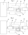
- the figure 3 thus schematically represents an embodiment of the invention, in which the motor vehicle battery management system is based on the series arrangement on a connection circuit connecting the drive battery 21 of the motor vehicle and its drive motor 22 of a device comprising the on-board battery 24 of the vehicle, which participates in the management of the charge of this on-board battery; for this reason, we will simply call charger 30 this device placed in series.
- a DC / DC converter 23 is also connected to the drive battery. Similar to the solution described with reference to the figure 1 , another DC / DC converter 28 can connect the drive battery 21 to the drive motor 22 for supplying the possible excitation in the case of a wound excitation motor.
- communication links 26, 27 allow the transmission of data representing respectively the state of the drive motor 22 and the on-board battery 24 to the DC / DC converter 23, which comprises hardware (hardware) and / or software components (software), in order to implement intelligent management of the entire management system, including in particular the control of the drive motor and the charge of the on-board battery via the charger 30, as will be explained later.
- the DC / DC converter 23 comprises hardware (hardware) and / or software components (software), in order to implement intelligent management of the entire management system, including in particular the control of the drive motor and the charge of the on-board battery via the charger 30, as will be explained later.
- the figure 4 represents the variant of the previous embodiment in the case of a three-phase motor.
- the motor is a three-phase motor 32, and the DC / DC converter 23 is replaced by an inverter 33.
- the on-board battery 24 of the motor vehicle can be recharged as soon as a current flows to or from the drive motor 22, 32.
- a bypass (not shown), managed by the charger 30, allows or not aware of passing through the onboard battery 24 of the vehicle, depending on its state of charge.
- This system is simplified compared to the solutions of the state of the art represented by the Figures 1 and 2 , in particular in that it comprises a DC / DC converter less, since it does not provide such an independent converter for charging the on-board battery 24 of the motor vehicle.
- the proposed system makes it possible to place the on-board battery charging system in series with the motor supply circuit, so as to use the inverter or the DC / DC converter supplying the drive motor as a means of '' adapt the voltage or current to the needs of the on-board battery to be charged.
- the inverter 33 or the DC / DC converter 23 drives the drive motor 32, 22 of the motor vehicle, by means of the current which is transmitted to it. For this, it automatically adjusts its output voltage to reach the setpoint current of the drive motor, and adapts at the same time automatically to the presence or not of the on-board network battery placed or not in series with the motor. drive, via the charger 30. This operation is carried out within the limit of a saturation of the output voltage of the inverter 33 or of the DC / DC converter 23. If we approach this saturation or if the on-board network battery is sufficiently charged, this battery can be isolated from the rest of the system, bypassed.
- the inverter 33 or the DC / DC converter 23 is informed of the serialization or not of the on-board battery 24 in order to take it into account and compensate for its output the voltage drop associated with placing the on-board battery in series.
- the figure 5 represents an alternative embodiment of the embodiment of the figure 4 , in which the inverter 33 is arranged between the charger 30 connected to the on-board battery 24 and the drive motor 32.
- This variant has in particular the advantage of integrating the charger 30 of the on-board battery 24 on a path two-wire power only (current reversal only when braking), and not on the three-phase system which can have more reactive power and make the management of battery recharging more complex (transient current reversal possible during each electrical period ).
- the charger 30 of the on-board battery 24 can be placed upstream or downstream of the DC / DC converter or of the inverter used for the supply of the motor or its excitation, on the embodiments of the figures 3 and 4 .
- the figure 6 represents in more detail a possible link between the charger 30 and the on-board battery 24 in the embodiment of the figure 3 .
- This charger 30 comprises a diode 36 and a switch 35 on a bypass path 37 of the on-board battery 24.
- the diode 36 is in series with the on-board battery 24 and makes it possible to guarantee the passage of a current Im positive for the charging of the on-board battery 24.
- This diode can alternatively be replaced by a controlled switch which is closed, and therefore conducting, only when the current Im is positive.
- the switch 35 is closed, the on-board battery 24 is by-passed from the management system, is no longer connected to the drive battery 21 of the vehicle and the charger 30 no longer implements its charge. .
- an equivalent alternative embodiment can be implemented in the case of a three-phase motor, according to the representation of the figure 4 , by placing the similar charger 30 in series on one of the phases of the motor or upstream of the converter and / or of the inverter, or by placing it on the supply line of the motor excitation.
- the charger 30 therefore makes it possible to arrange (or isolate) the on-board battery 24 in series with the drive battery 21 and the engine 22.
- the figure 7 shows in a simplified manner the electrical diagram of the previous embodiments, in which the inverter 33 or the DC / DC converter 23 can be considered as belonging to a first voltage source (comprising the drive battery 21) if they are arranged upstream of the onboard battery 24, as in the embodiments represented by figures 3, 4 , 6 , or belonging to load 22 if they are arranged downstream of the battery edge 24, as in the embodiment shown in figure 5 .
- the first voltage source supplies the load via the connection of its terminals P1, P2 and possibly P3 in the case of the three-phase.
- the terminals P1, P2, P3 are at different potentials and in the case shown in figure 1 the supply voltage between terminals P1 and P2 is called V1.
- the load is supplied by its input terminals P1 ', P2' and possibly P3 'brought to different potentials (potential difference V2 between terminals P1' and P2 ').
- This connection between the first voltage source and the load is obtained by a first link 25 connecting the first terminals P1, P1 'respectively of the first voltage source and the load, by a second link 29 connecting their second terminals P2, P2' and possibly a third link (not shown) between terminals P3 and P3 '.
- a link circuit is thus formed by the first, second and possibly third links 25, 29 between the first voltage source and the load, by which the first voltage source supplies the load.
- the onboard battery 24 is disposed on one of the links of this power path, in particular the first link 25 on the figure 7 , or alternatively not shown on the second or third link 29.
- the on-board battery 24 is therefore mounted in series on the link circuit (on a power path) arranged between the first voltage source and the load .
- this on-board battery 24 is crossed by a current Im, which is also the load supply current. It causes a voltage drop Vbat between the terminals P1 and P2.
- the figures 8 to 11 represent alternative embodiments of the charger 30 for the on-board battery 24 of the motor vehicle. These variant embodiments allow in particular the recharging of the on-board battery 24 whatever the direction of the current Im on the connection circuit connecting the drive battery 21 to the motor 22.
- FIGS 9 to 11 illustrate different variants which make it possible to reduce the number of switches for carrying out the figure 8 , while obtaining a substantially equivalent operation.
- These embodiments are based on a diode bridge 361 to 364, which allows the charge of the on-board battery 24 whatever the sign of the current Im, and on at least one switch 351 to allow the by-pass of the on-board battery 24.
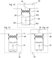
- the figures 12 to 15 represent alternative embodiments of the charger 30 for the on-board battery 24 of the motor vehicle. These variant embodiments allow recharging of the on-board battery 24, in the presence of a current Im of any direction on the connection circuit between the drive battery and the motor, as in the previous embodiments, while ensuring isolation galvanic of the on-board battery 24 relative to the drive battery 21 of the motor vehicle, which is very advantageous for a safety reason in certain implementations such as within a motor vehicle, a power tool, a bicycle, a bus or electric boat, an energy storage station serving as an energy buffer for the electricity grid, a solar installation (the solar cells replacing the drive battery 1 and the charger 30 being placed upstream or downstream of the inverter which returns energy to the sector) ...
- the variants of the charger 30, illustrated by the figures 12 to 15 comprise a current transformer 38, the primary circuit of which is disposed directly on the connection circuit connecting the drive battery to the motor.
- the on-board battery 24 of the vehicle is disposed on the secondary circuit of the transformer 38, by means of components similar to the embodiments of the figures 8 to 11 , i.e. a diode bridge and / or switches, to allow the on-board battery to be charged whatever the current Im flowing between the drive battery and the motor, and therefore whatever the direction of the current induced on the secondary circuit of the transformer 38.
- the switch 35 disposed at the circuit primary, either to close switches 352 and 353, or switches 351 and 354 of the secondary circuit.
- the use of the switch 35 of the primary circuit has the advantage of shunting the current transformer 38, which may have a certain resistive voltage drop, at the same time as the on-board battery 24.
- the by-pass of the current in the secondary circuit has the advantage in some cases of taking advantage of the slightly inductive behavior of the transformer 38, which can then improve the smoothing of the current on the power path between the drive battery and the motor.
- the transformer 38 fulfills a function of galvanic isolation of the secondary circuit, and therefore of the on-board battery 24 of the vehicle.
- the size of the transformer is defined in particular as a function of the frequency of the current applied: the higher the frequency of this current Im, the more this size can be reduced because the less the transformer will risk saturating.
- the transformation ratio is itself dimensioned so that the average current at the secondary relative to the average current of the power path is satisfactory to maintain a sufficient charge of the on-board battery.
- the charger 30 remains arranged in series with the drive battery and the engine, and allows the connection or isolation of the on-board battery of the vehicle with the link circuit connecting the drive battery to the engine.
- the variant of the figure 15 comprises a device arranged on the primary circuit intended to reverse the current of the primary circuit, which comprises four switches 355 to 358 in a similar manner to the solution described with reference to the figure 8 .
- This primary circuit allows the implementation of a reversal of the current Im flowing between the drive battery and the motor and entering the charger 30. This chopping / reversal of current can be done at a relatively high frequency compared to the natural frequency of the primary circuit current (e.g. 10 kHz), which reduces the size of the transformer.
- the use of this primary inverter is particularly important when the current Im is continuous or quasi-continuous, or at low frequency (for example less than 50 Hz), to allow the transformer 38 to induce a current in the secondary circuit.
- the primary current thus transmitted to the transformer 38 is equal to the current Im entering the charger 30 when the switches 355 and 357 are closed, the other two being open, and at the inverted value -Im when the switches 356 and 358 are closed, the two others being open.
- this By alternating the closings of the pairs of switches 355, 357 and 356,358 mentioned above, at a high frequency for example greater than 10 KHz, this generates an alternating current at the primary circuit which allows the transformer 38 to operate in a manner optimal.
- the on-board battery 24 can be disconnected from the system for example by closing the switches 355 and 358, and / or 356 and 357 of the device. arranged at the primary circuit of transformer 38 of charger 30.
- the switches mentioned can be of any kind, for example relays, or MOS, bipolar, thyristors, MOSFET, FET, etc., or diode type transistors, based on silicon technologies, Silicon carbide, Gallium arsenide, SOI or others ...
- the electrical management system comprises a control unit, not directly shown in the preceding figures, which can correspond to any hardware (hardware) and / or software (software) means of an intelligent management unit, comprising at least one computer, for example one or more microprocessors, to implement a control method.
- This management unit (or control unit) can be arranged or integrated within a DC / DC converter or an inverter, as mentioned above, or be any independent unit connected to the electrical management system by a communication device. .
- This management unit thus controls whether or not the on-board battery is linked with the link circuit connecting the drive battery and the motor, in series configuration on this link circuit or indirectly through galvanic isolation, in order to reach or not an on-board battery charging configuration.
- This method of managing the electrical system is first based on a regulation of electrical and / or mechanical parameters of the drive motor, such as for example a torque, a speed, an acceleration or a combination of these parameters, on the basis of an instruction supplied by a user of the system.
- This setpoint induces a minimum value of the input voltage of the DC / DC converter or of the inverter of the systems described above.
- the management unit authorizes or not the serialization of the on-board battery as a function of this minimum voltage, to avoid that the voltage drop which would be generated decreases the voltage available for the drive motor below the calculated minimum value.
- the state of the on-board battery is also taken into account, since it is not required to set up the charge configuration if its charge is not required.
- the electrical management system which compensates it immediately to comply with the instructions provided.
- the on-board battery can, in a preferred manner, be connected in series when this return current appears in order to absorb part of the associated energy.
- the management method comprises a step of detecting a return current, and takes such detection into account to promote the series connection of the on-board battery. This makes it possible to limit the microcycles that the drive battery can undergo if reactive power is present on the power path upstream of the converter 23, or 33, (that is to say comprising a positive current on part of the electric period then negative on a second part, as can happen for example when feeding a single-phase asynchronous motor).
- the on-board battery charger likewise comprises an intelligence, by means of a computer and hardware (hardware) and / or software (software) means, which implements a charging process for the vehicle's on-board battery, in particular by defining an optimal (medium) current setpoint for recharging the on-board battery.
- This current setpoint may depend on the state of charge and / or health and / or the temperature of the on-board battery.
- the on-board battery charging method calculates a charge configuration setting rate (for example its setting in series or the setting in series of the charger) of the on-board battery with the on-board battery. drive and motor, taking into account the defined setpoint and the average current Im flowing.
- the on-board battery is alternately connected and disconnected from the linkage circuit of the electrical management system according to an average duty cycle which makes it possible to reach an optimal compromise in order to reach the charge of the on-board battery while minimizing the operation. of the drive motor. Feedback of the average on-board battery serialization rate is implemented, in order to effectively reach the desired rate.
- the method of charging the on-board battery favors placing in series and therefore charging this battery when the current Im of the system is low, to avoid high current peaks.
- the method comprises a step of comparing the current Im with a chosen maximum value, and does not connect the on-board battery to the management system unless the current is lower than this chosen maximum value.
- this maximum current value is chosen to be compatible with obtaining the average battery recharge current corresponding to the desired charge current setpoint.
- the figure 16 represents curves of evolution as a function of time of electrical parameters in a scenario chosen by way of example, to illustrate the operation of the method for managing an electrical system with two batteries as described above.
- Curve 100 represents the voltage at the terminals of the drive battery as a function of time t
- curve 101 this voltage decreased in the event of charging of the on-board battery due to the loss of voltage generated
- curve 102 the minimum voltage required at the input of the DC / DC converter or of the inverter as a function of the need for the motor, as explained above.
- Curves 103 and 104 respectively illustrate the current Im flowing between the drive battery and the motor, and a maximum current defined as explained above.
- the drive battery consists of modules 112 or stages, arranged in series.
- each stage is arranged between two high and low potential levels, represented by two high 118 and low 117.
- Each module 112 comprises several cells 111, arranged in parallel on separate branches extending between the two levels. high and low potential of the module.
- Each cell 111 is associated with a switch 113 which is specific to it, arranged in series with its cell (on the branch between the two high and low potential levels of the module), which makes it possible to disconnect the cell from the rest of the battery. drive through its opening: for this we will call it "cell switch 113" later.
- each module 112 also includes a switch 114 in parallel with all the cells 111 of the module 112, thus making it possible to short-circuit the entire module: for this, we will call it “module switch 114” below. .
- the various switches 113, 114 are produced using power transistors, preferably NMOS type transistors, which provide a gain in conductivity in their on state compared to PMOS transistors which could alternatively be used.
- power transistors preferably NMOS type transistors
- other types of transistors such as bipolar, FET, JFET, IGBT, etc.
- silicon technology silicon carbide, or Gallium arsenide ...
- a control circuit 127 is electrically supplied by links 128 allowing it to recover a voltage difference corresponding substantially to the voltage of the most charged cell of the stage , slightly reduced by a voltage drop (for example close to 0.6 V) at the diodes 140 disposed on the links 128.
- This control circuit 127 has the function of generating control signals 141 to the various transistors forming the switches explained above to activate them, thus fulfilling a switch control function.
- all the electronic components of the module can be supplied according to the same solution, such as a computer making it possible to estimate the state of the switches, a possible communication system, etc.
- This local supply by at least one cell 111 of a module 112 ultimately relates to all the components requiring a supply.
- the control circuit 127 supplied by its associated module 112 or even by a neighboring module 112, is then electrically isolated from the other modules and / or electrical potentials external to the module.
- Such an embodiment has the advantage of eliminating the risk of driving a certain transistor with a potential very different from that of the stage, which could lead to its destruction or to its short-circuiting.
- this solution brings the additional advantage of allowing the reduction of connections between the components of the control circuit and the power source, since it is possible to group them at a short distance from each other and from the source. voltage, in particular by positioning the transistors as close as possible to the cells to be connected.
- the use of very short connections also greatly reduces any risk of short circuit, for example between two modules.
- each cell 111 further comprises at least one measurement sensor, not shown, of a quantity characteristic of the state of the cell.
- This measurement sensor can for example measure the voltage and / or the intensity and / or the temperature at the level of the cell concerned.
- Each measurement sensor is also connected by a communication device to an intelligent device, local and / or remote, such as a microcontroller type computer, which receives the measured values and implements a battery management method to determine a mode. optimized operation of the drive battery, taking into account the measurements made.
- This optimized operation consists in fact in determining the switches 113, 114 which must be open and closed.
- This configuration of the various battery switches can be modified in real time.
- This solution thus makes it possible for example to remove defective or overheated cells, to switch the current within each module, to balance each of the cells of the battery in real time.
- the average current requested by the motor supplied by the drive battery is generally much lower than the peak current requested at peak consumption, which allows the battery to operate with satisfaction most of the time with a number relatively large of disconnected cells, that is to say of which the associated cell switch 113 is open, or even of disconnected modules, that is to say of which the associated module switch 114 is closed, if the an entire module is considered to be defective or overheated, for example.
- the implementation of such a structure can be done using one or more electronic cards, physically integrated (s) at the level of cells 111 of energy storage, to position the electronic components described above as close as possible to the cells and form a perfectly integrated and compact unit.
- an electronic card in the form of a printed circuit can be positioned on the lower or upper face of each module and the drive battery can then include an electronic card between each module.
- the same electronic card can bring together the electronic components associated with several different modules, the cells of which are arranged with optimal bulk around this electronic card.
- the battery management method is implemented by the cooperation of a local control circuit 127, disposed at each module 112, connected to a central computer 122 by a bus communication 121 and via an interface 137 forming a galvanic isolation.
- a local processing circuit which can be a microcontroller with a sufficient number of input / output to interrogate all the sensors, can participate in the intelligent management of the drive battery and its switches, with or without assistance from a central computer 122.
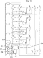
- the figure 17 illustrates an implementation of such a drive battery architecture, comprising by way of example four modules of two cells 111.
- all the modules of the drive battery have the structure described above, and are connected in series, the lower terminal 117 of an upper module representing the upper terminal 118 of a lower module.
- each module may naturally include a different number of cells and the drive battery may include more modules.
- the drive battery further includes four switches 186, 187, 188, 189, which are transistors according to this embodiment, controlled respectively by the battery control circuits, by control links 190. These switches form an H-shaped bridge making it possible to reverse the output of the drive battery.
- the on-board battery 24 of the vehicle is likewise arranged in series with the various modules of the drive battery and integrated into the structure described above, at the lower end of the stack of modules. It also has its serial switch 53 and its parallel switch 54, controlled by a specific control circuit 57, also connected to the same central computer 122 by the same communication bus 121, via an interface forming an isolation galvanic.
- the on-board battery can advantageously be associated with electronic components comparable to those associated with the storage cells of a module and described above.
- sensors for measuring current, and / or voltage, and / or temperature, not shown can be positioned at the on-board battery 24 and connected by means of communication to the control circuit 57 and / or to the computer 122.
- the on-board battery is thus physically connected and integrated into the drive battery, to form a global dual-function battery, integrating the engine drive battery and the on-board battery.
- the figure 18 describes an architecture very close to that of the figure 17 , which differs in that a multi-switch device, similar to that of the figure 8 , is installed at the on-board battery 24. Naturally, all the variants shown on the Figures 9 to 11 could also be implemented in such an architecture.
- the figures 19 and 20 similarly describe variants of architecture close to that of the figure 17 , in which a galvanic isolation by a transformer 38 is implemented at the on-board battery 24 of the vehicle, respectively implementing the solutions described with reference to the figures 12 and 15 .
- the switches of the secondary circuit of the transformer 38 are supplied by a control circuit 57 supplied by the on-board battery, while the switches positioned at the level of the primary circuit of the transformer 38 are supplied by a control circuit 127 of a neighboring module of the drive battery.
- the figure 21 illustrates an alternative embodiment of the figure 20 , in which the drive battery supplies a three-phase voltage, by means of a control of three branches of a three-phase inverter and a periodic chopping by switches 123 controlled by control circuits supplied by stages of the drive battery.
- the drive battery can include any architecture other than that described with reference to the Figures 17 to 21 .
- the different stages may include a different assembly of storage cells and switches than those shown.
- the concept described above can be extended to any system which combines two voltage sources of different levels, and more precisely to an electrical management system comprising a first voltage source and a second lower voltage source.
- the previously mentioned drive battery could be any other source of voltage, such as a simple electrical network, a photovoltaic device, a fuel cell, an electric energy generator, such as a dynamo or a turbine, etc.
- the motor could be any load to be supplied.
- the on-board battery can be replaced by any device with a lower voltage, any second source of lower voltage than a drive battery or a first source of voltage.
- the photovoltaic cells for producing electrical energy could correspond to the drive battery, to produce high-voltage energy supplying for example an electrical network, and a network with lower voltage, also from a limited number of photovoltaic cells or any battery, used to power an electronic device for managing the photovoltaic device could correspond to the on-board battery mentioned in the previous examples.
- the battery storage cells shown on the Figures 17 to 21 may alternatively be replaced by photovoltaic cells, possibly associated with capacities, or by any other element for producing and / or storing energy.
- a system comprising a low-voltage power supply system for supplying or recharging ancillary devices such as a television, a computer, a mobile telephone, etc., can use a solution as described in detail above.
Landscapes
- Engineering & Computer Science (AREA)
- Power Engineering (AREA)
- Life Sciences & Earth Sciences (AREA)
- Sustainable Development (AREA)
- Sustainable Energy (AREA)
- Transportation (AREA)
- Mechanical Engineering (AREA)
- Charge And Discharge Circuits For Batteries Or The Like (AREA)
- Electric Propulsion And Braking For Vehicles (AREA)
- Dc-Dc Converters (AREA)
Applications Claiming Priority (3)
| Application Number | Priority Date | Filing Date | Title |
|---|---|---|---|
| FR1250626A FR2986120B1 (fr) | 2012-01-23 | 2012-01-23 | Gestion combinee de deux sources de tension |
| PCT/EP2013/051226 WO2013110649A2 (fr) | 2012-01-23 | 2013-01-23 | Gestion combinee de deux sources de tension |
| EP13701081.5A EP2819873B1 (de) | 2012-01-23 | 2013-01-23 | Kombinierte steuerung von zwei spannungsquellen |
Related Parent Applications (2)
| Application Number | Title | Priority Date | Filing Date |
|---|---|---|---|
| EP13701081.5A Division EP2819873B1 (de) | 2012-01-23 | 2013-01-23 | Kombinierte steuerung von zwei spannungsquellen |
| EP13701081.5A Division-Into EP2819873B1 (de) | 2012-01-23 | 2013-01-23 | Kombinierte steuerung von zwei spannungsquellen |
Publications (2)
| Publication Number | Publication Date |
|---|---|
| EP3604020A1 true EP3604020A1 (de) | 2020-02-05 |
| EP3604020B1 EP3604020B1 (de) | 2024-01-03 |
Family
ID=47603726
Family Applications (2)
| Application Number | Title | Priority Date | Filing Date |
|---|---|---|---|
| EP13701081.5A Active EP2819873B1 (de) | 2012-01-23 | 2013-01-23 | Kombinierte steuerung von zwei spannungsquellen |
| EP19197685.1A Active EP3604020B1 (de) | 2012-01-23 | 2013-01-23 | Kombinierte steuerung von zwei spannungsquellen |
Family Applications Before (1)
| Application Number | Title | Priority Date | Filing Date |
|---|---|---|---|
| EP13701081.5A Active EP2819873B1 (de) | 2012-01-23 | 2013-01-23 | Kombinierte steuerung von zwei spannungsquellen |
Country Status (4)
| Country | Link |
|---|---|
| US (1) | US9948095B2 (de) |
| EP (2) | EP2819873B1 (de) |
| FR (1) | FR2986120B1 (de) |
| WO (1) | WO2013110649A2 (de) |
Families Citing this family (6)
| Publication number | Priority date | Publication date | Assignee | Title |
|---|---|---|---|---|
| US10033212B2 (en) | 2013-08-06 | 2018-07-24 | Analog Devices, Inc. | Battery cell with discretion to drive loads within battery stack |
| CN108832695B (zh) * | 2018-07-25 | 2020-11-17 | 珠海格力电器股份有限公司 | 直流微网系统、充电回路电路及其控制方法 |
| JP2022548710A (ja) | 2019-09-18 | 2022-11-21 | シェフラー テクノロジーズ アー・ゲー ウント コー. カー・ゲー | 駆動システムのエネルギー蓄積器を放電させるための回路 |
| CN113734076B (zh) * | 2020-05-29 | 2023-06-09 | 未势能源科技有限公司 | 供电系统和具有它的车辆 |
| US20220029431A1 (en) * | 2020-07-23 | 2022-01-27 | Aurora Flight Sciences Corporation, a subsidiary of The Boeing Company | Switchable Battery Management System |
| FR3143227A1 (fr) | 2022-12-09 | 2024-06-14 | Commissariat à l'énergie atomique et aux énergies alternatives | Système d’alimentation électrique alimentant une charge électrique via une tension polyphasée et en outre un réseau auxiliaire via une composante homopolaire de ladite tension, installation électrique associée |
Citations (10)
| Publication number | Priority date | Publication date | Assignee | Title |
|---|---|---|---|---|
| US20060232238A1 (en) * | 2005-03-29 | 2006-10-19 | Yusuke Horii | Battery charging system for hybrid electric vehicles |
| WO2009021909A1 (de) * | 2007-08-16 | 2009-02-19 | Zf Friedrichshafen Ag | Verfahren zum betrieb eines gleichstrom-spannungswandlers in einem hybridfahrzeug |
| WO2011016135A1 (ja) * | 2009-08-07 | 2011-02-10 | トヨタ自動車株式会社 | 電動車両の電源システム |
| US20110048825A1 (en) * | 2009-08-28 | 2011-03-03 | Gary Starr | Air conditioner for electric car |
| DE102009028965A1 (de) * | 2009-08-28 | 2011-03-03 | Robert Bosch Gmbh | Schaltung zum Betreiben eines Hilfsaggregat für den Start von Verbrennungsmaschinen |
| TW201116442A (en) * | 2009-09-15 | 2011-05-16 | Honda Motor Co Ltd | Wiring structure in electric two/three-wheeled vehicle |
| WO2011102543A1 (ja) * | 2010-02-19 | 2011-08-25 | Jfeエンジニアリング株式会社 | 急速充電装置及び移動式充電装置 |
| WO2011121035A1 (de) * | 2010-03-30 | 2011-10-06 | Continental Automotive Gmbh | Bordnetz für ein fahrzeug sowie steuervorrichtung für ein bordnetz |
| EP2374651A2 (de) * | 2010-04-07 | 2011-10-12 | FERRARI S.p.A. | Elektrisches System eines Fahrzeugs mit elektrischem Antrieb und Steuerverfahren dafür |
| EP2388902A1 (de) * | 2010-05-21 | 2011-11-23 | C.R.F. Società Consortile per Azioni | System und Verfahren zur digitalen Steuerung einer Gleichstromwandlervorrichtung, insbesondere für Automobilanwendungen |
Family Cites Families (16)
| Publication number | Priority date | Publication date | Assignee | Title |
|---|---|---|---|---|
| CN1049391C (zh) * | 1995-09-18 | 2000-02-16 | 精工爱普生株式会社 | 电动车辆的安全机构 |
| EP1458083B1 (de) * | 1999-06-09 | 2012-04-04 | Lear Corporation Holding Spain S.L. | Elektrisches verteilungssystem mit doppelspannung |
| US6452815B1 (en) * | 2001-02-22 | 2002-09-17 | Lizhi Zhu | Accelerated commutation for passive clamp isolated boost converters |
| US7378818B2 (en) * | 2002-11-25 | 2008-05-27 | Tiax Llc | Bidirectional power converter for balancing state of charge among series connected electrical energy storage units |
| WO2008007540A1 (en) * | 2006-07-10 | 2008-01-17 | Panasonic Corporation | Power supply device |
| DE102007004279A1 (de) * | 2007-01-23 | 2008-07-24 | Bayerische Motoren Werke Aktiengesellschaft | Mehrspannungsbordnetz für ein Kraftfahrzeug |
| US8482945B2 (en) * | 2008-09-26 | 2013-07-09 | Merstech, Inc. | Power converter with magnetic recovery switch |
| JP4478900B1 (ja) * | 2008-12-03 | 2010-06-09 | 本田技研工業株式会社 | 蓄電器加温装置 |
| JP5537913B2 (ja) * | 2009-11-30 | 2014-07-02 | 三洋電機株式会社 | 均等化装置、それを備えたバッテリシステムおよび電動車両 |
| US8384237B2 (en) * | 2010-07-27 | 2013-02-26 | Ford Global Technologies, Llc | Low voltage bus stability |
| US8901934B2 (en) * | 2010-10-29 | 2014-12-02 | GM Global Technology Operations LLC | Diagnosis of HEV/EV battery disconnect system |
| US9300139B2 (en) * | 2010-12-16 | 2016-03-29 | Ashot Nazarian | Method and apparatus for integrated electric power generation, storage and supply distributed and networked at the same time |
| US8765297B2 (en) * | 2011-01-04 | 2014-07-01 | Exide Technologies | Advanced graphite additive for enhanced cycle-life of lead-acid batteries |
| US8659184B2 (en) * | 2011-03-04 | 2014-02-25 | G.B.D. Corp. | Method and apparatus for powering an appliance |
| US9184605B2 (en) * | 2011-03-28 | 2015-11-10 | Changs Ascending Enterprise Co., Ltd. | High voltage battery system for vehicle applications |
| JP2012253942A (ja) * | 2011-06-03 | 2012-12-20 | Denso Corp | Dc−dcコンバータ装置 |
-
2012
- 2012-01-23 FR FR1250626A patent/FR2986120B1/fr active Active
-
2013
- 2013-01-23 EP EP13701081.5A patent/EP2819873B1/de active Active
- 2013-01-23 EP EP19197685.1A patent/EP3604020B1/de active Active
- 2013-01-23 WO PCT/EP2013/051226 patent/WO2013110649A2/fr not_active Ceased
- 2013-01-23 US US14/373,239 patent/US9948095B2/en active Active
Patent Citations (13)
| Publication number | Priority date | Publication date | Assignee | Title |
|---|---|---|---|---|
| US20060232238A1 (en) * | 2005-03-29 | 2006-10-19 | Yusuke Horii | Battery charging system for hybrid electric vehicles |
| WO2009021909A1 (de) * | 2007-08-16 | 2009-02-19 | Zf Friedrichshafen Ag | Verfahren zum betrieb eines gleichstrom-spannungswandlers in einem hybridfahrzeug |
| WO2011016135A1 (ja) * | 2009-08-07 | 2011-02-10 | トヨタ自動車株式会社 | 電動車両の電源システム |
| US20120187759A1 (en) * | 2009-08-07 | 2012-07-26 | Toyota Jidosha Kabushiki Kaisha | Power source system for electric powered vehicle |
| US20110048825A1 (en) * | 2009-08-28 | 2011-03-03 | Gary Starr | Air conditioner for electric car |
| DE102009028965A1 (de) * | 2009-08-28 | 2011-03-03 | Robert Bosch Gmbh | Schaltung zum Betreiben eines Hilfsaggregat für den Start von Verbrennungsmaschinen |
| EP2479091A1 (de) * | 2009-09-15 | 2012-07-25 | Honda Motor Co., Ltd. | Verkabelungsstruktur für ein elektrisch betriebenes zwei- oder dreirädriges fahrzeug |
| TW201116442A (en) * | 2009-09-15 | 2011-05-16 | Honda Motor Co Ltd | Wiring structure in electric two/three-wheeled vehicle |
| WO2011102543A1 (ja) * | 2010-02-19 | 2011-08-25 | Jfeエンジニアリング株式会社 | 急速充電装置及び移動式充電装置 |
| US20130049676A1 (en) * | 2010-02-19 | 2013-02-28 | Jfe Engineering Corporation | Quick charging device and mobile charging apparatus |
| WO2011121035A1 (de) * | 2010-03-30 | 2011-10-06 | Continental Automotive Gmbh | Bordnetz für ein fahrzeug sowie steuervorrichtung für ein bordnetz |
| EP2374651A2 (de) * | 2010-04-07 | 2011-10-12 | FERRARI S.p.A. | Elektrisches System eines Fahrzeugs mit elektrischem Antrieb und Steuerverfahren dafür |
| EP2388902A1 (de) * | 2010-05-21 | 2011-11-23 | C.R.F. Società Consortile per Azioni | System und Verfahren zur digitalen Steuerung einer Gleichstromwandlervorrichtung, insbesondere für Automobilanwendungen |
Also Published As
| Publication number | Publication date |
|---|---|
| EP3604020B1 (de) | 2024-01-03 |
| US20140361626A1 (en) | 2014-12-11 |
| FR2986120A1 (fr) | 2013-07-26 |
| WO2013110649A2 (fr) | 2013-08-01 |
| US9948095B2 (en) | 2018-04-17 |
| EP2819873B1 (de) | 2019-10-30 |
| FR2986120B1 (fr) | 2015-08-21 |
| WO2013110649A3 (fr) | 2014-12-04 |
| EP2819873A2 (de) | 2015-01-07 |
Similar Documents
| Publication | Publication Date | Title |
|---|---|---|
| EP2819873B1 (de) | Kombinierte steuerung von zwei spannungsquellen | |
| EP2718976B1 (de) | Photovoltaische ziegel mit serieller oder paralleler architektur | |
| EP2599206B1 (de) | Quadratischer doppelboost-gleichspannungswandler mit bidirektionalem strom | |
| EP3227137B1 (de) | Verbesserter gleichstromwandler und stromversorgungsvorrichtung | |
| EP2882069B1 (de) | System zur Energieumwandlung, Einheit zum Wiederaufladen durch Induktion, und entsprechende Verfahren zum Senden und Empfangen von Daten | |
| EP2020726A2 (de) | Verfahren zur Einspeisung von Notfall-Hilfsladungen, Hilfswandler und Schienenfahrzeug für dieses Verfahren | |
| FR2987509A1 (fr) | Circuit de charge d'une installation de stockage d'energie et son procede de charge | |
| EP3412500B1 (de) | Austauschverfahren von elektrischer energie zwischen einem elektrischen netz, in dem grosse mengen an gleich- oder wechselstrom fliessen, und einem speicher für elektrische energie für hybrid- oder elektrofahrzeug | |
| FR2981521A1 (fr) | Dispositif reversible de charge de batteries de vehicules electriques ou hybrides | |
| EP3389175B1 (de) | Umwandlungsvorrichtung, entsprechendes steuerverfahren und entsprechendes fahrzeug | |
| EP3183795B1 (de) | Batterieladegerät für hochintegriertes elektrisches oder hybrides kraftfahrzeug | |
| FR2980318A1 (fr) | Procede de reduction du courant de mode commun | |
| EP2801150A1 (de) | System zur bereitstellung einer wechselstromlast aus mehreren gleichspannungsquellen | |
| FR3005378A1 (fr) | Systeme et procede de charge de la batterie d'un vehicule electrique ou hybride | |
| FR2987511A1 (fr) | Dispositif de prise de tension continue pour une installation de stockage d'energie et procede pour generer une tension continue a partir d'une installation de stockage d'energie | |
| FR2978308A1 (fr) | Chargeur de batterie embarque dans un vehicule automobile, a alimentation electrique continue | |
| FR2996383A1 (fr) | Convertisseur de tension continu/continu reversible de type " flyback " | |
| FR3152758A1 (fr) | Procede d’equilibrage entre des lignes de courant d’une batterie d’un systeme electrique pendant une charge | |
| EP4099532A1 (de) | Stromversorgungssystem für mindestens eine elektrische antriebsmaschine eines kraftfahrzeugs, die durch mindestens zwei leistungsquellen gespeist wird | |
| FR3162947A1 (fr) | système d'alimentation électrique | |
| WO2024115185A1 (fr) | Systeme electrique d'alimentation pour vehicule | |
| WO2016193080A1 (fr) | Dispositif d'alimentation d'un recepteur electrique avec commutation entre deux sources de tension continue, et procede d'alimentation mettant en oeuvre un tel dispositif | |
| FR2983365A1 (fr) | Systeme de transfert d'energie electrique |
Legal Events
| Date | Code | Title | Description |
|---|---|---|---|
| PUAI | Public reference made under article 153(3) epc to a published international application that has entered the european phase |
Free format text: ORIGINAL CODE: 0009012 |
|
| STAA | Information on the status of an ep patent application or granted ep patent |
Free format text: STATUS: THE APPLICATION HAS BEEN PUBLISHED |
|
| AC | Divisional application: reference to earlier application |
Ref document number: 2819873 Country of ref document: EP Kind code of ref document: P |
|
| AK | Designated contracting states |
Kind code of ref document: A1 Designated state(s): AL AT BE BG CH CY CZ DE DK EE ES FI FR GB GR HR HU IE IS IT LI LT LU LV MC MK MT NL NO PL PT RO RS SE SI SK SM TR |
|
| STAA | Information on the status of an ep patent application or granted ep patent |
Free format text: STATUS: REQUEST FOR EXAMINATION WAS MADE |
|
| 17P | Request for examination filed |
Effective date: 20200803 |
|
| RBV | Designated contracting states (corrected) |
Designated state(s): AL AT BE BG CH CY CZ DE DK EE ES FI FR GB GR HR HU IE IS IT LI LT LU LV MC MK MT NL NO PL PT RO RS SE SI SK SM TR |
|
| STAA | Information on the status of an ep patent application or granted ep patent |
Free format text: STATUS: EXAMINATION IS IN PROGRESS |
|
| 17Q | First examination report despatched |
Effective date: 20211005 |
|
| GRAP | Despatch of communication of intention to grant a patent |
Free format text: ORIGINAL CODE: EPIDOSNIGR1 |
|
| RIC1 | Information provided on ipc code assigned before grant |
Ipc: H02J 7/34 20060101ALI20230626BHEP Ipc: B60L 58/10 20190101ALI20230626BHEP Ipc: H02J 1/06 20060101ALI20230626BHEP Ipc: H02J 7/00 20060101ALI20230626BHEP Ipc: H02J 7/14 20060101ALI20230626BHEP Ipc: B60L 50/51 20190101ALI20230626BHEP Ipc: B60L 50/62 20190101ALI20230626BHEP Ipc: B60L 53/14 20190101ALI20230626BHEP Ipc: B60L 58/20 20190101ALI20230626BHEP Ipc: B60L 58/22 20190101ALI20230626BHEP Ipc: B60L 58/40 20190101ALI20230626BHEP Ipc: B60L 3/00 20190101AFI20230626BHEP |
|
| STAA | Information on the status of an ep patent application or granted ep patent |
Free format text: STATUS: GRANT OF PATENT IS INTENDED |
|
| INTG | Intention to grant announced |
Effective date: 20230803 |
|
| GRAS | Grant fee paid |
Free format text: ORIGINAL CODE: EPIDOSNIGR3 |
|
| GRAA | (expected) grant |
Free format text: ORIGINAL CODE: 0009210 |
|
| STAA | Information on the status of an ep patent application or granted ep patent |
Free format text: STATUS: THE PATENT HAS BEEN GRANTED |
|
| AC | Divisional application: reference to earlier application |
Ref document number: 2819873 Country of ref document: EP Kind code of ref document: P |
|
| AK | Designated contracting states |
Kind code of ref document: B1 Designated state(s): AL AT BE BG CH CY CZ DE DK EE ES FI FR GB GR HR HU IE IS IT LI LT LU LV MC MK MT NL NO PL PT RO RS SE SI SK SM TR |
|
| REG | Reference to a national code |
Ref country code: GB Ref legal event code: FG4D Free format text: NOT ENGLISH |
|
| REG | Reference to a national code |
Ref country code: CH Ref legal event code: EP |
|
| REG | Reference to a national code |
Ref country code: DE Ref legal event code: R096 Ref document number: 602013085172 Country of ref document: DE |
|
| REG | Reference to a national code |
Ref country code: IE Ref legal event code: FG4D Free format text: LANGUAGE OF EP DOCUMENT: FRENCH |
|
| P01 | Opt-out of the competence of the unified patent court (upc) registered |
Effective date: 20240119 |
|
| REG | Reference to a national code |
Ref country code: LT Ref legal event code: MG9D |
|
| PG25 | Lapsed in a contracting state [announced via postgrant information from national office to epo] |
Ref country code: ES Free format text: LAPSE BECAUSE OF FAILURE TO SUBMIT A TRANSLATION OF THE DESCRIPTION OR TO PAY THE FEE WITHIN THE PRESCRIBED TIME-LIMIT Effective date: 20240103 |
|
| PG25 | Lapsed in a contracting state [announced via postgrant information from national office to epo] |
Ref country code: ES Free format text: LAPSE BECAUSE OF FAILURE TO SUBMIT A TRANSLATION OF THE DESCRIPTION OR TO PAY THE FEE WITHIN THE PRESCRIBED TIME-LIMIT Effective date: 20240103 |
|
| REG | Reference to a national code |
Ref country code: NL Ref legal event code: MP Effective date: 20240103 |
|
| REG | Reference to a national code |
Ref country code: AT Ref legal event code: MK05 Ref document number: 1646472 Country of ref document: AT Kind code of ref document: T Effective date: 20240103 |
|
| PG25 | Lapsed in a contracting state [announced via postgrant information from national office to epo] |
Ref country code: NL Free format text: LAPSE BECAUSE OF FAILURE TO SUBMIT A TRANSLATION OF THE DESCRIPTION OR TO PAY THE FEE WITHIN THE PRESCRIBED TIME-LIMIT Effective date: 20240103 |
|
| PG25 | Lapsed in a contracting state [announced via postgrant information from national office to epo] |
Ref country code: NL Free format text: LAPSE BECAUSE OF FAILURE TO SUBMIT A TRANSLATION OF THE DESCRIPTION OR TO PAY THE FEE WITHIN THE PRESCRIBED TIME-LIMIT Effective date: 20240103 |
|
| PG25 | Lapsed in a contracting state [announced via postgrant information from national office to epo] |
Ref country code: IS Free format text: LAPSE BECAUSE OF FAILURE TO SUBMIT A TRANSLATION OF THE DESCRIPTION OR TO PAY THE FEE WITHIN THE PRESCRIBED TIME-LIMIT Effective date: 20240503 |
|
| PG25 | Lapsed in a contracting state [announced via postgrant information from national office to epo] |
Ref country code: LT Free format text: LAPSE BECAUSE OF FAILURE TO SUBMIT A TRANSLATION OF THE DESCRIPTION OR TO PAY THE FEE WITHIN THE PRESCRIBED TIME-LIMIT Effective date: 20240103 |
|
| PG25 | Lapsed in a contracting state [announced via postgrant information from national office to epo] |
Ref country code: GR Free format text: LAPSE BECAUSE OF FAILURE TO SUBMIT A TRANSLATION OF THE DESCRIPTION OR TO PAY THE FEE WITHIN THE PRESCRIBED TIME-LIMIT Effective date: 20240404 |
|
| PG25 | Lapsed in a contracting state [announced via postgrant information from national office to epo] |
Ref country code: HR Free format text: LAPSE BECAUSE OF FAILURE TO SUBMIT A TRANSLATION OF THE DESCRIPTION OR TO PAY THE FEE WITHIN THE PRESCRIBED TIME-LIMIT Effective date: 20240103 Ref country code: RS Free format text: LAPSE BECAUSE OF FAILURE TO SUBMIT A TRANSLATION OF THE DESCRIPTION OR TO PAY THE FEE WITHIN THE PRESCRIBED TIME-LIMIT Effective date: 20240403 |
|
| PG25 | Lapsed in a contracting state [announced via postgrant information from national office to epo] |
Ref country code: AT Free format text: LAPSE BECAUSE OF FAILURE TO SUBMIT A TRANSLATION OF THE DESCRIPTION OR TO PAY THE FEE WITHIN THE PRESCRIBED TIME-LIMIT Effective date: 20240103 Ref country code: CZ Free format text: LAPSE BECAUSE OF FAILURE TO SUBMIT A TRANSLATION OF THE DESCRIPTION OR TO PAY THE FEE WITHIN THE PRESCRIBED TIME-LIMIT Effective date: 20240103 |
|
| PG25 | Lapsed in a contracting state [announced via postgrant information from national office to epo] |
Ref country code: RS Free format text: LAPSE BECAUSE OF FAILURE TO SUBMIT A TRANSLATION OF THE DESCRIPTION OR TO PAY THE FEE WITHIN THE PRESCRIBED TIME-LIMIT Effective date: 20240403 Ref country code: NO Free format text: LAPSE BECAUSE OF FAILURE TO SUBMIT A TRANSLATION OF THE DESCRIPTION OR TO PAY THE FEE WITHIN THE PRESCRIBED TIME-LIMIT Effective date: 20240403 Ref country code: LT Free format text: LAPSE BECAUSE OF FAILURE TO SUBMIT A TRANSLATION OF THE DESCRIPTION OR TO PAY THE FEE WITHIN THE PRESCRIBED TIME-LIMIT Effective date: 20240103 Ref country code: IS Free format text: LAPSE BECAUSE OF FAILURE TO SUBMIT A TRANSLATION OF THE DESCRIPTION OR TO PAY THE FEE WITHIN THE PRESCRIBED TIME-LIMIT Effective date: 20240503 Ref country code: HR Free format text: LAPSE BECAUSE OF FAILURE TO SUBMIT A TRANSLATION OF THE DESCRIPTION OR TO PAY THE FEE WITHIN THE PRESCRIBED TIME-LIMIT Effective date: 20240103 Ref country code: GR Free format text: LAPSE BECAUSE OF FAILURE TO SUBMIT A TRANSLATION OF THE DESCRIPTION OR TO PAY THE FEE WITHIN THE PRESCRIBED TIME-LIMIT Effective date: 20240404 Ref country code: CZ Free format text: LAPSE BECAUSE OF FAILURE TO SUBMIT A TRANSLATION OF THE DESCRIPTION OR TO PAY THE FEE WITHIN THE PRESCRIBED TIME-LIMIT Effective date: 20240103 Ref country code: BG Free format text: LAPSE BECAUSE OF FAILURE TO SUBMIT A TRANSLATION OF THE DESCRIPTION OR TO PAY THE FEE WITHIN THE PRESCRIBED TIME-LIMIT Effective date: 20240103 Ref country code: AT Free format text: LAPSE BECAUSE OF FAILURE TO SUBMIT A TRANSLATION OF THE DESCRIPTION OR TO PAY THE FEE WITHIN THE PRESCRIBED TIME-LIMIT Effective date: 20240103 |
|
| PG25 | Lapsed in a contracting state [announced via postgrant information from national office to epo] |
Ref country code: PL Free format text: LAPSE BECAUSE OF FAILURE TO SUBMIT A TRANSLATION OF THE DESCRIPTION OR TO PAY THE FEE WITHIN THE PRESCRIBED TIME-LIMIT Effective date: 20240103 Ref country code: PT Free format text: LAPSE BECAUSE OF FAILURE TO SUBMIT A TRANSLATION OF THE DESCRIPTION OR TO PAY THE FEE WITHIN THE PRESCRIBED TIME-LIMIT Effective date: 20240503 |
|
| REG | Reference to a national code |
Ref country code: DE Ref legal event code: R119 Ref document number: 602013085172 Country of ref document: DE Ref country code: DE Ref legal event code: R409 Ref document number: 602013085172 Country of ref document: DE |
|
| PG25 | Lapsed in a contracting state [announced via postgrant information from national office to epo] |
Ref country code: SE Free format text: LAPSE BECAUSE OF FAILURE TO SUBMIT A TRANSLATION OF THE DESCRIPTION OR TO PAY THE FEE WITHIN THE PRESCRIBED TIME-LIMIT Effective date: 20240103 Ref country code: PT Free format text: LAPSE BECAUSE OF FAILURE TO SUBMIT A TRANSLATION OF THE DESCRIPTION OR TO PAY THE FEE WITHIN THE PRESCRIBED TIME-LIMIT Effective date: 20240503 Ref country code: PL Free format text: LAPSE BECAUSE OF FAILURE TO SUBMIT A TRANSLATION OF THE DESCRIPTION OR TO PAY THE FEE WITHIN THE PRESCRIBED TIME-LIMIT Effective date: 20240103 Ref country code: LV Free format text: LAPSE BECAUSE OF FAILURE TO SUBMIT A TRANSLATION OF THE DESCRIPTION OR TO PAY THE FEE WITHIN THE PRESCRIBED TIME-LIMIT Effective date: 20240103 |
|
| REG | Reference to a national code |
Ref country code: CH Ref legal event code: PL |
|
| PG25 | Lapsed in a contracting state [announced via postgrant information from national office to epo] |
Ref country code: LU Free format text: LAPSE BECAUSE OF NON-PAYMENT OF DUE FEES Effective date: 20240123 |
|
| PG25 | Lapsed in a contracting state [announced via postgrant information from national office to epo] |
Ref country code: LU Free format text: LAPSE BECAUSE OF NON-PAYMENT OF DUE FEES Effective date: 20240123 |
|
| REG | Reference to a national code |
Ref country code: DE Ref legal event code: R097 Ref document number: 602013085172 Country of ref document: DE |
|
| PG25 | Lapsed in a contracting state [announced via postgrant information from national office to epo] |
Ref country code: DE Free format text: LAPSE BECAUSE OF NON-PAYMENT OF DUE FEES Effective date: 20240801 |
|
| PG25 | Lapsed in a contracting state [announced via postgrant information from national office to epo] |
Ref country code: DK Free format text: LAPSE BECAUSE OF FAILURE TO SUBMIT A TRANSLATION OF THE DESCRIPTION OR TO PAY THE FEE WITHIN THE PRESCRIBED TIME-LIMIT Effective date: 20240103 |
|
| PG25 | Lapsed in a contracting state [announced via postgrant information from national office to epo] |
Ref country code: SM Free format text: LAPSE BECAUSE OF FAILURE TO SUBMIT A TRANSLATION OF THE DESCRIPTION OR TO PAY THE FEE WITHIN THE PRESCRIBED TIME-LIMIT Effective date: 20240103 |
|
| PG25 | Lapsed in a contracting state [announced via postgrant information from national office to epo] |
Ref country code: CH Free format text: LAPSE BECAUSE OF NON-PAYMENT OF DUE FEES Effective date: 20240131 |
|
| PG25 | Lapsed in a contracting state [announced via postgrant information from national office to epo] |
Ref country code: EE Free format text: LAPSE BECAUSE OF FAILURE TO SUBMIT A TRANSLATION OF THE DESCRIPTION OR TO PAY THE FEE WITHIN THE PRESCRIBED TIME-LIMIT Effective date: 20240103 |
|
| PG25 | Lapsed in a contracting state [announced via postgrant information from national office to epo] |
Ref country code: SK Free format text: LAPSE BECAUSE OF FAILURE TO SUBMIT A TRANSLATION OF THE DESCRIPTION OR TO PAY THE FEE WITHIN THE PRESCRIBED TIME-LIMIT Effective date: 20240103 |
|
| RAP4 | Party data changed (patent owner data changed or rights of a patent transferred) |
Owner name: COMMISSARIAT A L'ENERGIE ATOMIQUE ET AUX ENERGIESALTERNATIVES |
|
| PG25 | Lapsed in a contracting state [announced via postgrant information from national office to epo] |
Ref country code: SM Free format text: LAPSE BECAUSE OF FAILURE TO SUBMIT A TRANSLATION OF THE DESCRIPTION OR TO PAY THE FEE WITHIN THE PRESCRIBED TIME-LIMIT Effective date: 20240103 Ref country code: SK Free format text: LAPSE BECAUSE OF FAILURE TO SUBMIT A TRANSLATION OF THE DESCRIPTION OR TO PAY THE FEE WITHIN THE PRESCRIBED TIME-LIMIT Effective date: 20240103 Ref country code: RO Free format text: LAPSE BECAUSE OF FAILURE TO SUBMIT A TRANSLATION OF THE DESCRIPTION OR TO PAY THE FEE WITHIN THE PRESCRIBED TIME-LIMIT Effective date: 20240103 Ref country code: EE Free format text: LAPSE BECAUSE OF FAILURE TO SUBMIT A TRANSLATION OF THE DESCRIPTION OR TO PAY THE FEE WITHIN THE PRESCRIBED TIME-LIMIT Effective date: 20240103 Ref country code: DK Free format text: LAPSE BECAUSE OF FAILURE TO SUBMIT A TRANSLATION OF THE DESCRIPTION OR TO PAY THE FEE WITHIN THE PRESCRIBED TIME-LIMIT Effective date: 20240103 Ref country code: DE Free format text: LAPSE BECAUSE OF NON-PAYMENT OF DUE FEES Effective date: 20240801 Ref country code: CH Free format text: LAPSE BECAUSE OF NON-PAYMENT OF DUE FEES Effective date: 20240131 |
|
| PLBE | No opposition filed within time limit |
Free format text: ORIGINAL CODE: 0009261 |
|
| STAA | Information on the status of an ep patent application or granted ep patent |
Free format text: STATUS: NO OPPOSITION FILED WITHIN TIME LIMIT |
|
| PG25 | Lapsed in a contracting state [announced via postgrant information from national office to epo] |
Ref country code: MC Free format text: LAPSE BECAUSE OF FAILURE TO SUBMIT A TRANSLATION OF THE DESCRIPTION OR TO PAY THE FEE WITHIN THE PRESCRIBED TIME-LIMIT Effective date: 20240103 |
|
| PG25 | Lapsed in a contracting state [announced via postgrant information from national office to epo] |
Ref country code: MC Free format text: LAPSE BECAUSE OF FAILURE TO SUBMIT A TRANSLATION OF THE DESCRIPTION OR TO PAY THE FEE WITHIN THE PRESCRIBED TIME-LIMIT Effective date: 20240103 |
|
| 26N | No opposition filed |
Effective date: 20241007 |
|
| GBPC | Gb: european patent ceased through non-payment of renewal fee |
Effective date: 20240403 |
|
| PG25 | Lapsed in a contracting state [announced via postgrant information from national office to epo] |
Ref country code: GB Free format text: LAPSE BECAUSE OF NON-PAYMENT OF DUE FEES Effective date: 20240403 |
|
| PG25 | Lapsed in a contracting state [announced via postgrant information from national office to epo] |
Ref country code: IE Free format text: LAPSE BECAUSE OF NON-PAYMENT OF DUE FEES Effective date: 20240123 |
|
| PG25 | Lapsed in a contracting state [announced via postgrant information from national office to epo] |
Ref country code: IE Free format text: LAPSE BECAUSE OF NON-PAYMENT OF DUE FEES Effective date: 20240123 Ref country code: GB Free format text: LAPSE BECAUSE OF NON-PAYMENT OF DUE FEES Effective date: 20240403 |
|
| PG25 | Lapsed in a contracting state [announced via postgrant information from national office to epo] |
Ref country code: SI Free format text: LAPSE BECAUSE OF FAILURE TO SUBMIT A TRANSLATION OF THE DESCRIPTION OR TO PAY THE FEE WITHIN THE PRESCRIBED TIME-LIMIT Effective date: 20240103 |
|
| PG25 | Lapsed in a contracting state [announced via postgrant information from national office to epo] |
Ref country code: CY Free format text: LAPSE BECAUSE OF FAILURE TO SUBMIT A TRANSLATION OF THE DESCRIPTION OR TO PAY THE FEE WITHIN THE PRESCRIBED TIME-LIMIT; INVALID AB INITIO Effective date: 20130123 |
|
| PG25 | Lapsed in a contracting state [announced via postgrant information from national office to epo] |
Ref country code: HU Free format text: LAPSE BECAUSE OF FAILURE TO SUBMIT A TRANSLATION OF THE DESCRIPTION OR TO PAY THE FEE WITHIN THE PRESCRIBED TIME-LIMIT; INVALID AB INITIO Effective date: 20130123 |
|
| PG25 | Lapsed in a contracting state [announced via postgrant information from national office to epo] |
Ref country code: FI Free format text: LAPSE BECAUSE OF FAILURE TO SUBMIT A TRANSLATION OF THE DESCRIPTION OR TO PAY THE FEE WITHIN THE PRESCRIBED TIME-LIMIT Effective date: 20240103 |
|
| PG25 | Lapsed in a contracting state [announced via postgrant information from national office to epo] |
Ref country code: TR Free format text: LAPSE BECAUSE OF FAILURE TO SUBMIT A TRANSLATION OF THE DESCRIPTION OR TO PAY THE FEE WITHIN THE PRESCRIBED TIME-LIMIT Effective date: 20240103 |
|
| PGFP | Annual fee paid to national office [announced via postgrant information from national office to epo] |
Ref country code: DE Payment date: 20260114 Year of fee payment: 14 |
|
| PGFP | Annual fee paid to national office [announced via postgrant information from national office to epo] |
Ref country code: BE Payment date: 20260119 Year of fee payment: 14 Ref country code: IT Payment date: 20260107 Year of fee payment: 14 |
|
| PGFP | Annual fee paid to national office [announced via postgrant information from national office to epo] |
Ref country code: FR Payment date: 20260128 Year of fee payment: 14 |