EP3604166A2 - Emballage pouvant être refermé et machine d'emboutissage-enveloppement sous pellicule et procédé - Google Patents
Emballage pouvant être refermé et machine d'emboutissage-enveloppement sous pellicule et procédé Download PDFInfo
- Publication number
- EP3604166A2 EP3604166A2 EP19188799.1A EP19188799A EP3604166A2 EP 3604166 A2 EP3604166 A2 EP 3604166A2 EP 19188799 A EP19188799 A EP 19188799A EP 3604166 A2 EP3604166 A2 EP 3604166A2
- Authority
- EP
- European Patent Office
- Prior art keywords
- clamping section
- packaging
- shell
- deep
- mold
- Prior art date
- Legal status (The legal status is an assumption and is not a legal conclusion. Google has not performed a legal analysis and makes no representation as to the accuracy of the status listed.)
- Withdrawn
Links
- 238000004806 packaging method and process Methods 0.000 title claims abstract description 80
- 238000000034 method Methods 0.000 title claims abstract description 9
- 238000007789 sealing Methods 0.000 claims abstract description 29
- 238000003856 thermoforming Methods 0.000 claims description 20
- 238000000465 moulding Methods 0.000 claims description 12
- 239000000853 adhesive Substances 0.000 claims description 5
- 230000001070 adhesive effect Effects 0.000 claims description 5
- 238000006073 displacement reaction Methods 0.000 claims description 5
- 238000001816 cooling Methods 0.000 claims description 3
- 230000032258 transport Effects 0.000 description 4
- 238000010276 construction Methods 0.000 description 3
- 244000208734 Pisonia aculeata Species 0.000 description 2
- 238000005452 bending Methods 0.000 description 2
- 239000011888 foil Substances 0.000 description 2
- 238000004519 manufacturing process Methods 0.000 description 2
- 238000007493 shaping process Methods 0.000 description 2
- 230000005540 biological transmission Effects 0.000 description 1
- 230000015572 biosynthetic process Effects 0.000 description 1
- 238000011161 development Methods 0.000 description 1
- 230000018109 developmental process Effects 0.000 description 1
- 230000000694 effects Effects 0.000 description 1
- 235000013305 food Nutrition 0.000 description 1
- 238000010438 heat treatment Methods 0.000 description 1
- 238000007373 indentation Methods 0.000 description 1
- 230000000977 initiatory effect Effects 0.000 description 1
- 230000009191 jumping Effects 0.000 description 1
- 230000002787 reinforcement Effects 0.000 description 1
- 230000001360 synchronised effect Effects 0.000 description 1
Images


Classifications
-
- B—PERFORMING OPERATIONS; TRANSPORTING
- B65—CONVEYING; PACKING; STORING; HANDLING THIN OR FILAMENTARY MATERIAL
- B65B—MACHINES, APPARATUS OR DEVICES FOR, OR METHODS OF, PACKAGING ARTICLES OR MATERIALS; UNPACKING
- B65B9/00—Enclosing successive articles, or quantities of material, e.g. liquids or semiliquids, in flat, folded, or tubular webs of flexible sheet material; Subdividing filled flexible tubes to form packages
- B65B9/02—Enclosing successive articles, or quantities of material between opposed webs
- B65B9/04—Enclosing successive articles, or quantities of material between opposed webs one or both webs being formed with pockets for the reception of the articles, or of the quantities of material
-
- B—PERFORMING OPERATIONS; TRANSPORTING
- B65—CONVEYING; PACKING; STORING; HANDLING THIN OR FILAMENTARY MATERIAL
- B65D—CONTAINERS FOR STORAGE OR TRANSPORT OF ARTICLES OR MATERIALS, e.g. BAGS, BARRELS, BOTTLES, BOXES, CANS, CARTONS, CRATES, DRUMS, JARS, TANKS, HOPPERS, FORWARDING CONTAINERS; ACCESSORIES, CLOSURES, OR FITTINGS THEREFOR; PACKAGING ELEMENTS; PACKAGES
- B65D77/00—Packages formed by enclosing articles or materials in preformed containers, e.g. boxes, cartons, sacks or bags
- B65D77/10—Container closures formed after filling
- B65D77/20—Container closures formed after filling by applying separate lids or covers, i.e. flexible membrane or foil-like covers
- B65D77/2024—Container closures formed after filling by applying separate lids or covers, i.e. flexible membrane or foil-like covers the cover being welded or adhered to the container
- B65D77/2068—Means for reclosing the cover after its first opening
- B65D77/2096—Adhesive means
-
- B—PERFORMING OPERATIONS; TRANSPORTING
- B29—WORKING OF PLASTICS; WORKING OF SUBSTANCES IN A PLASTIC STATE IN GENERAL
- B29C—SHAPING OR JOINING OF PLASTICS; SHAPING OF MATERIAL IN A PLASTIC STATE, NOT OTHERWISE PROVIDED FOR; AFTER-TREATMENT OF THE SHAPED PRODUCTS, e.g. REPAIRING
- B29C51/00—Shaping by thermoforming, i.e. shaping sheets or sheet like preforms after heating, e.g. shaping sheets in matched moulds or by deep-drawing; Apparatus therefor
- B29C51/18—Thermoforming apparatus
- B29C51/20—Thermoforming apparatus having movable moulds or mould parts
- B29C51/22—Thermoforming apparatus having movable moulds or mould parts rotatable about an axis
-
- B—PERFORMING OPERATIONS; TRANSPORTING
- B29—WORKING OF PLASTICS; WORKING OF SUBSTANCES IN A PLASTIC STATE IN GENERAL
- B29C—SHAPING OR JOINING OF PLASTICS; SHAPING OF MATERIAL IN A PLASTIC STATE, NOT OTHERWISE PROVIDED FOR; AFTER-TREATMENT OF THE SHAPED PRODUCTS, e.g. REPAIRING
- B29C51/00—Shaping by thermoforming, i.e. shaping sheets or sheet like preforms after heating, e.g. shaping sheets in matched moulds or by deep-drawing; Apparatus therefor
- B29C51/26—Component parts, details or accessories; Auxiliary operations
- B29C51/42—Heating or cooling
- B29C51/427—Cooling of the material with a fluid blast
-
- B—PERFORMING OPERATIONS; TRANSPORTING
- B29—WORKING OF PLASTICS; WORKING OF SUBSTANCES IN A PLASTIC STATE IN GENERAL
- B29C—SHAPING OR JOINING OF PLASTICS; SHAPING OF MATERIAL IN A PLASTIC STATE, NOT OTHERWISE PROVIDED FOR; AFTER-TREATMENT OF THE SHAPED PRODUCTS, e.g. REPAIRING
- B29C66/00—General aspects of processes or apparatus for joining preformed parts
- B29C66/80—General aspects of machine operations or constructions and parts thereof
- B29C66/84—Specific machine types or machines suitable for specific applications
- B29C66/849—Packaging machines
-
- B—PERFORMING OPERATIONS; TRANSPORTING
- B65—CONVEYING; PACKING; STORING; HANDLING THIN OR FILAMENTARY MATERIAL
- B65B—MACHINES, APPARATUS OR DEVICES FOR, OR METHODS OF, PACKAGING ARTICLES OR MATERIALS; UNPACKING
- B65B47/00—Apparatus or devices for forming pockets or receptacles in or from sheets, blanks, or webs, comprising essentially a die into which the material is pressed or a folding die through which the material is moved
- B65B47/04—Apparatus or devices for forming pockets or receptacles in or from sheets, blanks, or webs, comprising essentially a die into which the material is pressed or a folding die through which the material is moved by application of mechanical pressure
-
- B—PERFORMING OPERATIONS; TRANSPORTING
- B65—CONVEYING; PACKING; STORING; HANDLING THIN OR FILAMENTARY MATERIAL
- B65B—MACHINES, APPARATUS OR DEVICES FOR, OR METHODS OF, PACKAGING ARTICLES OR MATERIALS; UNPACKING
- B65B47/00—Apparatus or devices for forming pockets or receptacles in or from sheets, blanks, or webs, comprising essentially a die into which the material is pressed or a folding die through which the material is moved
- B65B47/08—Apparatus or devices for forming pockets or receptacles in or from sheets, blanks, or webs, comprising essentially a die into which the material is pressed or a folding die through which the material is moved by application of fluid pressure
- B65B47/10—Apparatus or devices for forming pockets or receptacles in or from sheets, blanks, or webs, comprising essentially a die into which the material is pressed or a folding die through which the material is moved by application of fluid pressure by vacuum
-
- B—PERFORMING OPERATIONS; TRANSPORTING
- B65—CONVEYING; PACKING; STORING; HANDLING THIN OR FILAMENTARY MATERIAL
- B65B—MACHINES, APPARATUS OR DEVICES FOR, OR METHODS OF, PACKAGING ARTICLES OR MATERIALS; UNPACKING
- B65B7/00—Closing containers or receptacles after filling
- B65B7/16—Closing semi-rigid or rigid containers or receptacles not deformed by, or not taking-up shape of, contents, e.g. boxes or cartons
- B65B7/28—Closing semi-rigid or rigid containers or receptacles not deformed by, or not taking-up shape of, contents, e.g. boxes or cartons by applying separate preformed closures, e.g. lids, covers
- B65B7/2842—Securing closures on containers
-
- B—PERFORMING OPERATIONS; TRANSPORTING
- B65—CONVEYING; PACKING; STORING; HANDLING THIN OR FILAMENTARY MATERIAL
- B65D—CONTAINERS FOR STORAGE OR TRANSPORT OF ARTICLES OR MATERIALS, e.g. BAGS, BARRELS, BOTTLES, BOXES, CANS, CARTONS, CRATES, DRUMS, JARS, TANKS, HOPPERS, FORWARDING CONTAINERS; ACCESSORIES, CLOSURES, OR FITTINGS THEREFOR; PACKAGING ELEMENTS; PACKAGES
- B65D1/00—Rigid or semi-rigid containers having bodies formed in one piece, e.g. by casting metallic material, by moulding plastics, by blowing vitreous material, by throwing ceramic material, by moulding pulped fibrous material or by deep-drawing operations performed on sheet material
- B65D1/34—Trays or like shallow containers
-
- B—PERFORMING OPERATIONS; TRANSPORTING
- B65—CONVEYING; PACKING; STORING; HANDLING THIN OR FILAMENTARY MATERIAL
- B65D—CONTAINERS FOR STORAGE OR TRANSPORT OF ARTICLES OR MATERIALS, e.g. BAGS, BARRELS, BOTTLES, BOXES, CANS, CARTONS, CRATES, DRUMS, JARS, TANKS, HOPPERS, FORWARDING CONTAINERS; ACCESSORIES, CLOSURES, OR FITTINGS THEREFOR; PACKAGING ELEMENTS; PACKAGES
- B65D77/00—Packages formed by enclosing articles or materials in preformed containers, e.g. boxes, cartons, sacks or bags
- B65D77/10—Container closures formed after filling
- B65D77/20—Container closures formed after filling by applying separate lids or covers, i.e. flexible membrane or foil-like covers
- B65D77/2024—Container closures formed after filling by applying separate lids or covers, i.e. flexible membrane or foil-like covers the cover being welded or adhered to the container
- B65D77/2068—Means for reclosing the cover after its first opening
- B65D77/2072—Mechanical means
- B65D77/2076—Mechanical means provided by the cover itself
- B65D77/2084—Mechanical means provided by the cover itself the cover being maintained reclosed by a part folded over the container rim
-
- B—PERFORMING OPERATIONS; TRANSPORTING
- B29—WORKING OF PLASTICS; WORKING OF SUBSTANCES IN A PLASTIC STATE IN GENERAL
- B29C—SHAPING OR JOINING OF PLASTICS; SHAPING OF MATERIAL IN A PLASTIC STATE, NOT OTHERWISE PROVIDED FOR; AFTER-TREATMENT OF THE SHAPED PRODUCTS, e.g. REPAIRING
- B29C51/00—Shaping by thermoforming, i.e. shaping sheets or sheet like preforms after heating, e.g. shaping sheets in matched moulds or by deep-drawing; Apparatus therefor
- B29C51/26—Component parts, details or accessories; Auxiliary operations
- B29C51/30—Moulds
- B29C51/34—Moulds for undercut articles
-
- B—PERFORMING OPERATIONS; TRANSPORTING
- B29—WORKING OF PLASTICS; WORKING OF SUBSTANCES IN A PLASTIC STATE IN GENERAL
- B29L—INDEXING SCHEME ASSOCIATED WITH SUBCLASS B29C, RELATING TO PARTICULAR ARTICLES
- B29L2031/00—Other particular articles
- B29L2031/712—Containers; Packaging elements or accessories, Packages
-
- B—PERFORMING OPERATIONS; TRANSPORTING
- B65—CONVEYING; PACKING; STORING; HANDLING THIN OR FILAMENTARY MATERIAL
- B65D—CONTAINERS FOR STORAGE OR TRANSPORT OF ARTICLES OR MATERIALS, e.g. BAGS, BARRELS, BOTTLES, BOXES, CANS, CARTONS, CRATES, DRUMS, JARS, TANKS, HOPPERS, FORWARDING CONTAINERS; ACCESSORIES, CLOSURES, OR FITTINGS THEREFOR; PACKAGING ELEMENTS; PACKAGES
- B65D2577/00—Packages formed by enclosing articles or materials in preformed containers, e.g. boxes, cartons, sacks, bags
- B65D2577/10—Container closures formed after filling
- B65D2577/20—Container closures formed after filling by applying separate lids or covers
- B65D2577/2025—Multi-layered container, e.g. laminated, coated
- B65D2577/2033—Multi-layered container, e.g. laminated, coated with one or more layers of container being torn off upon initial opening
-
- B—PERFORMING OPERATIONS; TRANSPORTING
- B65—CONVEYING; PACKING; STORING; HANDLING THIN OR FILAMENTARY MATERIAL
- B65D—CONTAINERS FOR STORAGE OR TRANSPORT OF ARTICLES OR MATERIALS, e.g. BAGS, BARRELS, BOTTLES, BOXES, CANS, CARTONS, CRATES, DRUMS, JARS, TANKS, HOPPERS, FORWARDING CONTAINERS; ACCESSORIES, CLOSURES, OR FITTINGS THEREFOR; PACKAGING ELEMENTS; PACKAGES
- B65D2577/00—Packages formed by enclosing articles or materials in preformed containers, e.g. boxes, cartons, sacks, bags
- B65D2577/10—Container closures formed after filling
- B65D2577/20—Container closures formed after filling by applying separate lids or covers
- B65D2577/2041—Pull tabs
- B65D2577/205—Pull tabs integral with the closure
-
- B—PERFORMING OPERATIONS; TRANSPORTING
- B65—CONVEYING; PACKING; STORING; HANDLING THIN OR FILAMENTARY MATERIAL
- B65D—CONTAINERS FOR STORAGE OR TRANSPORT OF ARTICLES OR MATERIALS, e.g. BAGS, BARRELS, BOTTLES, BOXES, CANS, CARTONS, CRATES, DRUMS, JARS, TANKS, HOPPERS, FORWARDING CONTAINERS; ACCESSORIES, CLOSURES, OR FITTINGS THEREFOR; PACKAGING ELEMENTS; PACKAGES
- B65D2577/00—Packages formed by enclosing articles or materials in preformed containers, e.g. boxes, cartons, sacks, bags
- B65D2577/10—Container closures formed after filling
- B65D2577/20—Container closures formed after filling by applying separate lids or covers
- B65D2577/2066—Means on, or attached to, container flange facilitating opening, e.g. non-bonding region, cut-out
-
- B—PERFORMING OPERATIONS; TRANSPORTING
- B65—CONVEYING; PACKING; STORING; HANDLING THIN OR FILAMENTARY MATERIAL
- B65D—CONTAINERS FOR STORAGE OR TRANSPORT OF ARTICLES OR MATERIALS, e.g. BAGS, BARRELS, BOTTLES, BOXES, CANS, CARTONS, CRATES, DRUMS, JARS, TANKS, HOPPERS, FORWARDING CONTAINERS; ACCESSORIES, CLOSURES, OR FITTINGS THEREFOR; PACKAGING ELEMENTS; PACKAGES
- B65D2577/00—Packages formed by enclosing articles or materials in preformed containers, e.g. boxes, cartons, sacks, bags
- B65D2577/10—Container closures formed after filling
- B65D2577/20—Container closures formed after filling by applying separate lids or covers
- B65D2577/2075—Lines of weakness or apertures
- B65D2577/2083—Lines of weakness or apertures in container flange
Definitions
- the present invention relates to a reclosable packaging and a thermoforming packaging machine for producing such packaging and a method for operating the thermoforming packaging machine.
- Packaging is increasingly being used which comprises a shell which is deep-drawn from a stable lower film or hard film and which is closed with an upper film. Particularly for food products, these packages can be resealed after the first opening, which is achieved, for example, by an adhesive seam that at least partially maintains their effect.
- Such packaging is for example from the DE 10 2015 205 221 A1 known. However, it has been found that the adhesive seam often no longer provides sufficient adhesive force, in particular after repeated opening and closing, in order to prevent the interior of the packaging from exchanging air with the surroundings.
- the deep-drawn shells of the packaging are usually designed in a rectangular cross-sectional shape, in the form of a parallelogram or in a trapezoidal shape, in which the horizontal cross-section of the shell tapers from top to bottom.
- the tray can be removed upwards or diagonally upwards from a mold cavity after the bottom film has been deep-drawn, for example in FIG US 5,014,500 shown.
- the object of the present invention is to provide a packaging with an improved reclosing mechanism and a thermoforming packaging machine for producing such a packaging.
- thermoforming packaging machine according to claim 8 and a method for operating a thermoforming packaging machine according to claim 15.
- Advantageous further developments are specified in the subclaims.
- a packaging according to the invention in particular thermoformed film packaging, comprises a tray for inserting a product with a substantially horizontal edge running around an upper side of the tray, to which a clamping section is detachably connected at least in sections by means of a dividing line.
- the dividing line can be a cutting line or perforation and can be designed to open and thus separate the clamping section from the horizontal edge when the clamping section is angled or kinked around the dividing line from the horizontal.
- the packaging further comprises an upper film which extends at least in sections over the shell, the edge and the clamping section and is detachably connected to the edge with a circumferential first sealing seam and thus closes the shell in a gas-tight manner.
- the top film is connected to the clamping section with a second sealing seam.
- a rear pull which has a projection, the projection being suitable for locking the clamping section when the clamping section is detached from the edge at the dividing line and at least in sections between the projection of the rear pull and the side surface the shell is located.
- the packaging can be opened by pulling the top film off the tray.
- the clamping section which was separated from the horizontal edge of the shell by a bending movement, remains connected to the upper film.
- a section of the upper film expediently on a side of the shell opposite the clamping section, remains connected to the latter by not completely pulling off the upper film.
- the packaging can now be closed again by placing the top film back on the tray and pivoting the clamping section still connected to the top film down and between the side surface adjacent to the clamping section and the projection of the rear pull formed on this side surface is clamped.
- the top film tightens and lies essentially flat on the upper horizontal edge of the shell and closes it with it.
- the packaging can furthermore be opened and closed several times, the product remaining in the packaging being stored essentially airtight.
- the distance between a vertex of the projection and the dividing line is expediently less than a width of the clamping section. This ensures that the clamping section cannot release itself from the locking mechanism.
- sections of the packaging tray are elastically bent with a certain amount of force, for example the upper edge of the tray adjacent to the clamping section or the side surface on which the rear pull is formed.
- the clamping section has a contour designed in this way in order to ensure sufficient strength of the clamping section so that it remains locked when a tensile force is exerted on the upper film.
- the contour which can be, for example, a notch formed in sections or continuously over the length of the clamping section, can already be formed during deep drawing.
- structured surfaces have a higher flexural and torsional strength than completely flat surfaces. Accordingly, an unwanted bending of the clamping section and a release from the locking is prevented.
- the clamping section has a third sealing seam.
- the clamping section is thus connected to a total of two sealing seams and is therefore particularly stably connected to the upper film.
- the contour can be arranged in the center and the top film can be connected to the clamping section on both sides of the contour.
- the rear profile viewed in the lateral profile, essentially corresponds to a quarter of an oval.
- the backing therefore has no hard corners or edges, particularly on its outer shape, which improves the feel and appearance of the packaging, especially since it does not cause such corners and edges to be pressed in or deformed, and also when locking the Forces occurring in the clamping section can advantageously be derived into the side surface of the shell.
- the second and / or third sealing seam is preferably non-detachable.
- the sealing seams that connect the top film to the clamping section cannot be accidentally pulled open by the consumer.
- the first sealing seam is preferably designed as a reclosable adhesive connection.
- the top film can also be pressed on again to seal the packaging particularly airtight. Together with the holding down of the film by clamping the clamping section behind the projection of the pull-back, a particularly reliable airtight closure of the packaging is achieved.
- a deep-drawing packaging machine for producing a packaging, in particular a packaging according to the preceding description, comprises a molding station for deep-drawing a bottom film, the molding station in turn comprising a lower mold part with a mold cavity and the mold cavity having a wall segment which is designed with a side surface of the package to form a deceit.
- the wall segment comprises an upper part and a lower part and is displaceably mounted from a first position, in which the mold cavity is in a deep-drawing configuration, to a second position, in which the mold cavity is in a removal configuration.
- the deep-drawing configuration is suitable for deep-drawing the bottom film
- the removal configuration is suitable for lowering the lower part of the mold and thus for removing the packaging, in particular without collisions.
- the upper part is articulated on the lower part in order to be displaced therewith and thereby execute a rotary movement relative to the lower part.
- the wall segment including the upper and lower part, is arranged so that the molding station can be closed by bringing an upper mold part into contact with the lower mold part.
- the bottom film introduced into the molding station can then be deep-drawn into the mold cavity by forming a pressure difference between its top and bottom and, if necessary, by heating. it adapts to the surfaces and contours of the mold cavity, creating a suitably shaped shell.
- the molding station is opened and, for example, the lower part of the mold is moved downwards in order to release the shell for lateral removal.
- the shell and the mold trough are not readily possible, since the rear recess formed on one side surface would collide with the wall segment. This is remedied by moving the wall segment to the side away from the mold cavity. Since a package of the type described at the outset has a rear section with a projection arranged on it at the top, a mere lateral displacement is also not possible, since the projection would collide with the wall segment.
- a cutting tool can also be integrated in the forming station in order to cut the dividing line between the clamping section and the upper edge of the shell as a cut line or perforation.
- a cutting tool can also be provided separately and expediently as the next station of the thermoforming packaging machine downstream. This is usually followed by a station for inserting the products into the tray, a sealing station for closing the tray with an upper film, and a cutting station for cutting and separating the sealed packages.
- the top part is hinged to the bottom part such that the top part, when performing the rotational movement while moving the wall segment, always remains below its uppermost vertical extension, which it has in the position when the mold cavity is in the deep-drawing configuration.
- the movements of the wall segment are hindered by other sections of the mold trough or the deep-drawn bottom film and, for example, a wall segment is only moved with simultaneous vertical movement of the deep-drawn shell or can be rotated.
- the upper part does not abut an upper edge of the shell when the rotary movement is carried out. It can therefore also serve itself as a contact surface for shaping the upper edge of the shell.
- moving the wall segment and releasing the packaging tray can be planned as a process in the manufacturing process that is independent of the actual removal of the packaging trays.
- the upper part is articulated on an axis of rotation arranged on the lower part.
- This is a particularly simple and expedient construction, since the upper part does not require any further guides or connections on or with the lower part of the mold. Accordingly, the power transmission for initiating the rotary movement takes place only via the lower part of the displaceable wall segment.
- the upper part usually lies in a form-fitting manner on the lower part in the deep-drawing configuration of the mold cavity.
- the upper part can rest against the lower part in such a way that a molding pressure occurring during deep drawing is diverted into the lower part and thus an unwanted one Rotation around the axis of rotation is prevented.
- a contact surface of the upper part is formed at an end remote from the axis of rotation.
- the upper part is articulated on the lower part with a resetting mechanism, in particular a spring, in order to automatically return to an end position when the wall segment is moved.
- a resetting mechanism in particular a spring
- the mold lower part preferably has nozzle bores in order to blow air onto the wall segment for cooling purposes, the nozzle bores being closed when the mold cavity is in the deep-drawing configuration and are active when the mold cavity is in the removal configuration.
- the opening and closing of the nozzle bores can be carried out by an independent mechanism that is synchronized with the movement of the wall segment.
- a section of the wall segment itself can cover or uncover the nozzle bores in an airtight manner.
- cooling of the wall segment can take place in the open state if the air can flow out.
- thermoforming packaging machine has a linear drive which engages with a slide in order to move it, and the slide has a curved control groove.
- the displaceable wall segment comprises a pin which engages with the control groove, so that the wall segment is displaced linearly when the drive is actuated.
- this is a particularly space-saving arrangement which translates a linear movement into a linear movement perpendicular thereto.
- the slide can be designed with a plurality of control grooves in order to move a plurality of wall segments lying next to one another at the same time.
- the slide is mounted and the control groove is shaped so that the wall segment cannot be pressed open by a molding pressure, since only a lateral movement of the slide, parallel to the mold cavity, can cause the wall segment to shift.
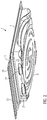
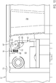
- Figure 1 shows a deep-drawn packaging 1, comprising a shell 3 and an upper film, which is not shown here for the sake of clarity.
- a circumferential, horizontal edge 7 is formed on an upper side 5 of the shell 3, on which a first sealing seam 9 forms the shell 3 the top film connects.
- a clamping section 13 is arranged on the edge 7 via a dividing line 11, which can be a pre-cut or a perforation.
- the one-piece top film is connected to the clamping section 13 via a second and third sealing seam 15, 17.
- the clamping section 13 has a centrally arranged contour 19.
- the sealed packaging 1 is separated and cut after the sealing process, so that the top film with the shell 3, in particular with the edge 7 and the clamping section 13, is congruent in its horizontal shape.
- Two rear extensions 23 are formed on a side surface 21.
- the shell 3 has further structures 25 in order to improve the stability and handling of the packaging 1.
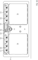
- Figure 2 shows the package 1 in an oblique view from below.
- the two rear extensions 23 can be seen, which essentially correspond to a quarter of an oval in cross section.
- the hind legs 23 each have a projection 27, behind which the clamping section 13 is clamped when the package 1 is closed again.
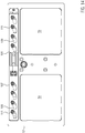
- Figure 3 shows the packaging 1 Figure 1 and 2 , in which the clamping section 13 was folded down on the dividing line 11 and pushed behind the projections 27.
- the clamping section 13 is expediently grasped and the upper film connected to it is at least partially removed from the shell 3, the first sealing seam 9 being released, but at least on the side of the edge 7 opposite the clamping section 13, the upper film and the shell 3 remains connected over part of the sealing seam 9.
- the clamping section 13 can be clamped behind the projections 27 and locked by the latter, the upper film stretching and exerting an outward pull on the clamping section 13.
- the clamping section 13 is clamped behind the projections 27 and the removal takes place with an elastic bend or twisting of the clamping section 13 and / or the rear sections 23 or other parts of the shell 3, with sufficient stability being present in the locked position shown to enable an independent movement To prevent the clamping section 13 from jumping out.
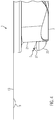
- Figure 4 shows a side sectional view of a package 1 with rear pull 23 and clamping section 13.
- the profile of the rear pull 23 and the projection 27 can be seen, the highest point of which is the apex S. From the apex S to the side surface 21, the profile of the Projection 27 here in a straight line, but it can also be concave, for example.
- the clamping section 13 has the contour 19 in the form of a downward bulge.
- Figure 5 shows the side sectional view of a package 1 according to Figure 4 , wherein the clamping portion 13 is pivoted down on the dividing line 11 and locked behind the projection 27.
- a width B of the clamping section 13 is larger than the direct distance A of the vertex S from the dividing line 11.
- the different sections are for clamping the clamping section 13 behind the projection 27 and for releasing the shell 3 is suitable to be elastically deformed to a small extent.
- the clamping section 13 can be bent slightly, an upward force can be exerted on the upper horizontal edge 7 and finally the side surface 21 can also twist to a limited extent.
- FIG. 6 shows a schematic view of a thermoformed packaging machine 41 with a forming station 43, a sealing station 45 and a cutting device 47.
- a lower film 49 is first rolled off a roll and, for example, clamped on both sides in transport chains, is fed to the forming station 43, where a tray 3 with a pull-back 23 is deep-drawn type described above.
- a cutting tool can be provided in the forming station 43 or separately.
- the dividing line 11 is expediently cut or perforated after the deep-drawing of the shell 3, since it should only be present in the lower foil 49, but not in the upper foil 53 spanning it.
- a product 51 is inserted into the shell 3 and the shell 3 sealed in the sealing station 45 with the top film 53.
- the deep drawing, filling and sealing can be carried out for each work step for one or also for several trays 3 which are arranged next to one another and / or one behind the other.
- the packaging 1 is then cut and separated by means of the cutting device 47, for example with round corner cuts of the upper edge 7 and the clamping section 13.
- a removal unit 55 transports the packaging 1 out of the thermoforming packaging machine 41.
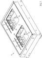
- Figure 7 shows a perspective view of a lower mold part 57 with two mold cavities 59 in a deep-drawing configuration.
- Each mold cavity 59 has two displaceable wall segments 61, which comprise an upper part 63 and a lower part 65.
- the wall segments 61 are arranged in a form-fitting and flush manner with the adjacent inner side surfaces 67 of the mold depression 59 and have a recess 69 for forming the rear pull-out 23.
- An upper support surface 71 is used to form the upper horizontal edge 7 and Clamping section 13, wherein the edge 7 is later cut to the desired dimensions by means of the cutting device 47.
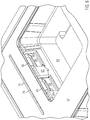
- Figure 8 shows an enlarged perspective view of a mold trough 59 in the removal configuration.
- the wall segments 61 are displaced outward, as a result of which the rear sections 23 of a deep-drawn shell 3 are released for vertical movement. Since a projection 27 is formed on the upper side of the rear extensions 23, the upper parts 63 of the wall segments 61 are rotated about the projections 27 in addition to their horizontal movement, for example by an angle of approximately 30 °.
- Figure 9 shows a side sectional view of a mold cavity 59 or the mold lower part 57 in a deep-drawing configuration accordingly Figure 7 ,
- the wall segment 61 and thus its upper part 63 and lower part 65 are flush with the other side surfaces 67 of the mold cavity 59 and form the desired profile for forming the rear section 23 and the projection 27 of the shell 3.
- one or more air channels 81 can be provided in the upper part 63 to form a negative pressure.
- the air duct 81 is expediently arranged at a most withdrawn position of the recesses 69, 79.
- the upper part 63 not only closes positively with the adjacent side surfaces 67 of the mold depression 59, but also abuts the lower part 65 of the wall segment 61 with a lateral section 83. As a result, a molding pressure can be derived from the stably mounted lower part 65.
- Figure 10 shows a side sectional view of a mold cavity 59 or the mold lower part 57 in the removal configuration accordingly Figure 8 .
- the wall segment 61 is displaced outwards, to the left in this illustration, in order to release the shell 3 for vertical removal.
- the wall segment 61 is therefore moved into a position in which the rear pull 23 does not collide with the wall segment 61, in particular the upper part 63, when the lower part 57 of the mold is lowered.
- the upper part 63 is rotatably supported about an axis of rotation 85 and is rotated when the wall segment 61 is moved upward around the projection 27 into the position shown.
- the axis of rotation 85 is mounted on the lower part 65. Due to the shape of an upper edge 87 of the upper part 63, this always remains below its uppermost vertical extent, which the upper part 63 also assumes during the deep-drawing configuration, during the rotation through the relevant angular range.
- the upper edge 87 is designed in the form of a circular arc concentric about the axis of rotation 85, this shape also being suitable for shaping the shell 3 at the same time.
- a reset mechanism 89 here in the form of a spiral spring, is connected to the upper part 63 via a lever section 91 and is mounted on the lower part 65, and can cause the upper part 63 to rotate into a corresponding end position by means of a tensile or compressive force.
- a nozzle bore 93 is formed in the lower mold part 57, which is closed, for example in the deep-drawing configuration of the lower mold part 57, by the wall segment 61 and is released in the removal configuration as shown in order to allow an air flow on and along the wall segment 61 and to cool it.
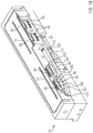
- Figure 11 shows a perspective view of four wall segments 61 with drive components in the positions for the deep-drawing configuration.
- the representation is comparable to an exploded drawing, the relative arrangement of the components being indicated by dashed lines.
- a linear drive 101 for example an electric motor or a pneumatic cylinder, comprises a rod, at the end of which a plate 103 is arranged, the drive 101 being configured to move the plate 103 back and forth along the direction of movement Z.
- the plate 103 engages with a clamp 105 of a slide 107 and causes the slide 107 to move accordingly.
- the slide 107 has one or more curved control grooves 109, in each of which a pin 111 of the wall segment 61 is slidably mounted.
- the wall segment 61 is mounted in guides of the lower mold part 57 such that the movement of the slide 107 along the direction of movement Z causes the wall segment 61 to move perpendicularly thereto.
- Wall segments 61 each with two pins 111 are shown here. However, it is also conceivable to provide only one pin 111, for example arranged in the center, per wall segment 61.
- Figure 12 shows a perspective view of four wall segments 61 with drive components in removal configuration. Compared to Figure 11 is the plate 103, and thus the slide 107, moved to the right by means of a rod 113. Since the wall segments 61 have no degree of freedom of movement in the direction Z due to their guidance in the lower mold part 57, they only perform a movement perpendicular thereto, caused by the control groove 109. At the same time, the rotational movement of the upper parts 63 of the wall segment 61 is caused.
- Figure 13 shows a horizontal sectional view of a lower mold part 57 in a deep-drawing configuration.
- the plate 103 is in a retracted position and the slide 107 in a position on the right in this illustration.
- the control groove 109 thus move the pin 111 and thus the wall segment 61 so that a shell 3 can be deep drawn.
- Figure 14 shows a horizontal sectional view of a mold lower part 57 in the removal configuration.
- the slide 107 is shifted to the left so that the pins 111 and thus the wall segments 61 are moved away from the mold cavity 59 in order to allow the lower part of the mold 57 to be lowered and thus the further transport of the shells 3 after the deep-drawing.
- Figure 15 shows a perspective view of an angled section of the lower mold part 57 in a deep-drawing configuration corresponding to FIG Figures 11 and 13 ,
- the side surface 67 of the mold cavity 59 is shown in order to show the flush termination of the wall segments 61 with precisely this side surface 67 in the deep-drawing configuration.
- the side face 67 has been left open to show the slide 107.
- Figure 16 shows a perspective view of an angled section of the mold lower part 57 in the removal configuration corresponding to FIG Figures 12 and 14 ,
- the wall segments 61 are moved away from the mold depression 59 and outwards by means of the control groove 109 and the pins 111 arranged therein due to the rightward displacement of the slide 107.
- the upper parts 63 are rotated.
- a lower film 49 is first fed to a molding station 43, clamped in it between a lower mold part 57 and an upper mold part when the forming station 43 is closed, and then deep-drawn into a mold 3 to form a shell 3 with the formation of suitable temperatures and pressure differences. Doing so by means of a suitable recess 69, which is formed in a displaceable wall segment 61, a rear pull 23 with a projection 27 is formed on a side surface 21.
- a dividing line 11 between an upper edge 7 and a clamping section 13, which is formed as an extension of the upper edge 7, is then cut or perforated in or subsequent to the forming station 43, the dividing line 11 being designed such that the clamping section 13 is initially in Connection to the edge 7 remains, but detaches from the edge 7 at a first kink at the dividing line 11.
- the wall segment 61 is displaced outward and away from the mold cavity 59.
- An upper part 63 of the wall segment 61 additionally executes a rotary movement so that it does not collide with a projection 27 of the rear section 23 during the horizontal displacement movement of the wall segment 61.
- the shell 3 is filled with a product 51 and sealed in a gas-tight manner in a sealing station 45 with an upper film 53.
- the upper film 53 extends both over the edge 7 of the shell 3 and over the clamping section 13 and there is a first sealing seam 9 on the edge 7 and a second sealing seam 15 on the clamping section 13 and optionally a third sealing seam 17 with the upper film 53 trained.
- the contour of the upper edge 7 and of the clamping section 13 is then cut in a cutting device 47, the corners preferably being given a round cut. If several trays 3 are formed and sealed next to or in succession per work step in the thermoforming packaging machine 41, the packages 1 are also separated by means of the cutting device 47. The individual packages 1 are removed by means of a removal unit 55.
- the mold trough 59 can also have a round or oval shape on the side in order to produce corresponding packagings 1, the wall segments 61 also being adapted accordingly.
- the displaceable wall segments 61 can also have knobs, pins or the like in order to form contours protruding into the pack.
Landscapes
- Engineering & Computer Science (AREA)
- Mechanical Engineering (AREA)
- Ceramic Engineering (AREA)
- Physics & Mathematics (AREA)
- Fluid Mechanics (AREA)
- Moulds For Moulding Plastics Or The Like (AREA)
- Vacuum Packaging (AREA)
- Closing Of Containers (AREA)
Applications Claiming Priority (1)
| Application Number | Priority Date | Filing Date | Title |
|---|---|---|---|
| DE102018212836.7A DE102018212836A1 (de) | 2018-08-01 | 2018-08-01 | Wiederverschließbare Verpackung sowie Tiefziehverpackungsmaschine und Verfahren |
Publications (2)
| Publication Number | Publication Date |
|---|---|
| EP3604166A2 true EP3604166A2 (fr) | 2020-02-05 |
| EP3604166A3 EP3604166A3 (fr) | 2020-05-20 |
Family
ID=67514315
Family Applications (1)
| Application Number | Title | Priority Date | Filing Date |
|---|---|---|---|
| EP19188799.1A Withdrawn EP3604166A3 (fr) | 2018-08-01 | 2019-07-29 | Emballage pouvant être refermé et machine d'emboutissage-enveloppement sous pellicule et procédé |
Country Status (3)
| Country | Link |
|---|---|
| US (1) | US11485561B2 (fr) |
| EP (1) | EP3604166A3 (fr) |
| DE (1) | DE102018212836A1 (fr) |
Families Citing this family (2)
| Publication number | Priority date | Publication date | Assignee | Title |
|---|---|---|---|---|
| USD871208S1 (en) * | 2017-11-20 | 2019-12-31 | Frank Brunckhorst Co., L.L.C. | Container |
| US11077603B1 (en) * | 2020-03-23 | 2021-08-03 | Jay Baker | Method of producing a packaging container with a closure and release mechanism and retention elements |
Citations (3)
| Publication number | Priority date | Publication date | Assignee | Title |
|---|---|---|---|---|
| US5014500A (en) | 1989-06-16 | 1991-05-14 | Mecaplastic | Device and installation for forming and closing trays |
| EP2570351A1 (fr) | 2011-09-16 | 2013-03-20 | Multivac Sepp Haggenmüller GmbH & Co. KG | Machine d'emballage par emboutissage pour la fabrication d'emballages verticaux ayant une coupe arrière moulée |
| DE102015205221A1 (de) | 2015-03-23 | 2016-09-29 | Multivac Sepp Haggenmüller Se & Co. Kg | Tiefziehverpackungsmaschine, Verfahren und Verpackung |
Family Cites Families (15)
| Publication number | Priority date | Publication date | Assignee | Title |
|---|---|---|---|---|
| US3371848A (en) * | 1966-10-24 | 1968-03-05 | Anderson Bros Mfg Co | Reclosable package |
| US3398876A (en) * | 1967-02-06 | 1968-08-27 | Anderson Bros Mfg Co | Reclosable package |
| US3398877A (en) * | 1967-04-10 | 1968-08-27 | Anderson Bros Mfg Co | Reclosable package |
| US3495759A (en) * | 1968-04-24 | 1970-02-17 | Anderson Bros Mfg Co | Reclosable package |
| DE2323425B2 (de) * | 1973-05-09 | 1975-12-11 | Multivac Sepp Haggenmueller Kg, 8941 Wolfertschwenden | Formwerkzeug mit einem Element zum Formen eines Vorsprungs zum Verformen von Kunststoff-Folien |
| FR2318790A1 (fr) * | 1975-07-24 | 1977-02-18 | Bourbon Claude | Coquille a contre-depouille pour emballer un produit rigide par encliquetage, et dispositif pour sa fabrication |
| US4495135A (en) * | 1982-08-09 | 1985-01-22 | Baxter Travenol Laboratories, Inc. | Method for forming container having re-entrant flange |
| CH677473A5 (en) * | 1988-12-02 | 1991-05-31 | Alusuisse | Container with resealable cover - has edge with weakened zones forming cone parting surface widening towards top |
| FR2880834B1 (fr) * | 2005-01-19 | 2009-03-27 | Erca Formseal Sa | "dispositif et procede de thermoformage d'objets ayant une collerette de base, et objets ainsi obtenus |
| DE202006000955U1 (de) * | 2006-01-23 | 2006-05-18 | Striebel, Christhard | Kindersichere Folienverpackung für Medikamente in Tablettenform |
| US8127573B2 (en) * | 2006-04-04 | 2012-03-06 | Emhart Glass S.A. | Mold cooling system for I.S. machine |
| FR3002922B1 (fr) * | 2013-03-06 | 2015-10-30 | Cgl Pack Service | Barquette a opercule refermable |
| WO2016057046A1 (fr) * | 2014-10-10 | 2016-04-14 | Bemis Company, Inc. | Emballage pelable refermable avec fermeture par clip |
| JP6528987B2 (ja) * | 2015-03-23 | 2019-06-12 | 大日本印刷株式会社 | 蓋付容器 |
| DE102015217886A1 (de) * | 2015-09-17 | 2017-03-23 | Thyssenkrupp Ag | Verschiebeelement zum Verschieben eines Nockensegmentes |
-
2018
- 2018-08-01 DE DE102018212836.7A patent/DE102018212836A1/de not_active Withdrawn
-
2019
- 2019-07-29 EP EP19188799.1A patent/EP3604166A3/fr not_active Withdrawn
- 2019-08-01 US US16/529,212 patent/US11485561B2/en active Active
Patent Citations (4)
| Publication number | Priority date | Publication date | Assignee | Title |
|---|---|---|---|---|
| US5014500A (en) | 1989-06-16 | 1991-05-14 | Mecaplastic | Device and installation for forming and closing trays |
| EP2570351A1 (fr) | 2011-09-16 | 2013-03-20 | Multivac Sepp Haggenmüller GmbH & Co. KG | Machine d'emballage par emboutissage pour la fabrication d'emballages verticaux ayant une coupe arrière moulée |
| EP2570351B1 (fr) * | 2011-09-16 | 2015-03-25 | Multivac Sepp Haggenmüller GmbH & Co. KG | Machine d'emballage par emboutissage pour la fabrication d'emballages verticaux ayant une coupe arrière moulée |
| DE102015205221A1 (de) | 2015-03-23 | 2016-09-29 | Multivac Sepp Haggenmüller Se & Co. Kg | Tiefziehverpackungsmaschine, Verfahren und Verpackung |
Also Published As
| Publication number | Publication date |
|---|---|
| US20200039716A1 (en) | 2020-02-06 |
| DE102018212836A1 (de) | 2020-02-06 |
| EP3604166A3 (fr) | 2020-05-20 |
| US11485561B2 (en) | 2022-11-01 |
Similar Documents
| Publication | Publication Date | Title |
|---|---|---|
| DE60005611T2 (de) | Verfahren zur Befestigung eines Schiebers an einer wiederverschliessbaren Verpackung aus flexiblem Material | |
| EP2029446B1 (fr) | Paquet de cigarettes à couvercle rabattable | |
| AT398744B (de) | Vorrichtung zum herstellen eines behälters, vorzugsweise eines gefüllten behälters, aus einem flachen zuschnitt | |
| DE2026964A1 (de) | Verschlußbehälter sowie Verfahren und Vorrichtung zur Herstellung desselben | |
| EP0808676A1 (fr) | Procédé de fabrication d'un couvercle de boîte à ouverture facile et couvercle de boîte à ouverture facile | |
| DE102008051026A1 (de) | Transportmittel und Verpackungsmaschine für Folienbreitenanpassung | |
| DE1461996A1 (de) | Verpackungsmaschine | |
| DE10105699A1 (de) | Verfahren und Vorrichtung zum Herstellen eines diffusionsdichten Kunststoffbehälters | |
| EP3604166A2 (fr) | Emballage pouvant être refermé et machine d'emboutissage-enveloppement sous pellicule et procédé | |
| DE4122692B4 (de) | Vorrichtung zum Umhüllen quaderförmiger Gegenstände | |
| EP2804706B1 (fr) | Procédé de fabrication d'une boîte métallique à opercule déchirable et boîte à opercule déchirable | |
| EP0708025B1 (fr) | Machine vertical à former, remplir et fermer des sachets | |
| EP4161767A1 (fr) | Dispositif et procédé pour fabriquer des contenants pourvus d'un bord fonctionnel à partir de découpes planes | |
| DE4432296A1 (de) | Kunststoffverpackung mit über eine Faltkante angelenkter Oberwand, Verfahren zur Herstellung derselben und Vorrichtung zur Durchführung des Verfahrens | |
| EP0453715A2 (fr) | Dispositif pour l'emboutissage d'une coquille ouverte | |
| EP2284082B1 (fr) | Procédé d'emballage de produits | |
| DE102016119818B3 (de) | Mehrteilige Verpackung | |
| DE102015016079B4 (de) | Verfahren und Vorrichtung zum Falten eines Zuschnittes aus Hüllmaterial für die Herstellung eines Einsatzes für eine steife Rauchwarenverpackung | |
| DE102011004297B3 (de) | Mehrteilige Formschulter | |
| EP4259531A1 (fr) | Procédé et dispositif de fabrication de flans pour des rebords de paquets pour cigarettes | |
| DE102005029492B4 (de) | Vorrichtung zur Herstellung einer Schlauchbeutelverpackung | |
| DE1461996C (de) | Verpackungsmaschine zum Vakuumverpak ken | |
| DE19506953C2 (de) | Verschlußdeckel für Behältnisse und Verfahren zur Herstellung derartiger Verschlußdeckel | |
| DE102004026207B4 (de) | Formvorrichtung und Verfahren zum Ausformen eines Behältnisses aus einer thermoplastischen Bahn und zur In-Mould-Etikettierung des Behältnisses | |
| DE1586460C (de) | Verpackung sowie Verfahren und Vornch tung zu deren Herstellung |
Legal Events
| Date | Code | Title | Description |
|---|---|---|---|
| PUAI | Public reference made under article 153(3) epc to a published international application that has entered the european phase |
Free format text: ORIGINAL CODE: 0009012 |
|
| STAA | Information on the status of an ep patent application or granted ep patent |
Free format text: STATUS: THE APPLICATION HAS BEEN PUBLISHED |
|
| AK | Designated contracting states |
Kind code of ref document: A2 Designated state(s): AL AT BE BG CH CY CZ DE DK EE ES FI FR GB GR HR HU IE IS IT LI LT LU LV MC MK MT NL NO PL PT RO RS SE SI SK SM TR |
|
| AX | Request for extension of the european patent |
Extension state: BA ME |
|
| PUAL | Search report despatched |
Free format text: ORIGINAL CODE: 0009013 |
|
| AK | Designated contracting states |
Kind code of ref document: A3 Designated state(s): AL AT BE BG CH CY CZ DE DK EE ES FI FR GB GR HR HU IE IS IT LI LT LU LV MC MK MT NL NO PL PT RO RS SE SI SK SM TR |
|
| AX | Request for extension of the european patent |
Extension state: BA ME |
|
| RIC1 | Information provided on ipc code assigned before grant |
Ipc: B29C 51/34 20060101ALI20200415BHEP Ipc: B65D 77/20 20060101AFI20200415BHEP Ipc: B29L 31/00 20060101ALI20200415BHEP Ipc: B65B 47/10 20060101ALN20200415BHEP |
|
| STAA | Information on the status of an ep patent application or granted ep patent |
Free format text: STATUS: REQUEST FOR EXAMINATION WAS MADE |
|
| 17P | Request for examination filed |
Effective date: 20201117 |
|
| RBV | Designated contracting states (corrected) |
Designated state(s): AL AT BE BG CH CY CZ DE DK EE ES FI FR GB GR HR HU IE IS IT LI LT LU LV MC MK MT NL NO PL PT RO RS SE SI SK SM TR |
|
| STAA | Information on the status of an ep patent application or granted ep patent |
Free format text: STATUS: EXAMINATION IS IN PROGRESS |
|
| 17Q | First examination report despatched |
Effective date: 20220621 |
|
| GRAP | Despatch of communication of intention to grant a patent |
Free format text: ORIGINAL CODE: EPIDOSNIGR1 |
|
| STAA | Information on the status of an ep patent application or granted ep patent |
Free format text: STATUS: GRANT OF PATENT IS INTENDED |
|
| RIC1 | Information provided on ipc code assigned before grant |
Ipc: B65B 47/10 20060101ALN20230424BHEP Ipc: B65B 9/04 20060101ALI20230424BHEP Ipc: B29L 31/00 20060101ALI20230424BHEP Ipc: B29C 51/34 20060101ALI20230424BHEP Ipc: B65D 77/20 20060101AFI20230424BHEP |
|
| INTG | Intention to grant announced |
Effective date: 20230524 |
|
| P01 | Opt-out of the competence of the unified patent court (upc) registered |
Effective date: 20230801 |
|
| STAA | Information on the status of an ep patent application or granted ep patent |
Free format text: STATUS: THE APPLICATION IS DEEMED TO BE WITHDRAWN |
|
| 18D | Application deemed to be withdrawn |
Effective date: 20231005 |