EP3604699A1 - Assemblage connectant pour des installations hydrauliques-sanitaires - Google Patents
Assemblage connectant pour des installations hydrauliques-sanitaires Download PDFInfo
- Publication number
- EP3604699A1 EP3604699A1 EP19187999.8A EP19187999A EP3604699A1 EP 3604699 A1 EP3604699 A1 EP 3604699A1 EP 19187999 A EP19187999 A EP 19187999A EP 3604699 A1 EP3604699 A1 EP 3604699A1
- Authority
- EP
- European Patent Office
- Prior art keywords
- connecting assembly
- hydraulic
- chamber
- sanitary
- cold water
- Prior art date
- Legal status (The legal status is an assumption and is not a legal conclusion. Google has not performed a legal analysis and makes no representation as to the accuracy of the status listed.)
- Withdrawn
Links
- XLYOFNOQVPJJNP-UHFFFAOYSA-N water Substances O XLYOFNOQVPJJNP-UHFFFAOYSA-N 0.000 claims abstract description 50
- 230000008878 coupling Effects 0.000 claims description 7
- 238000010168 coupling process Methods 0.000 claims description 7
- 238000005859 coupling reaction Methods 0.000 claims description 7
- 238000002955 isolation Methods 0.000 claims description 4
- 238000003466 welding Methods 0.000 claims description 3
- 238000010146 3D printing Methods 0.000 claims description 2
- 238000000465 moulding Methods 0.000 claims description 2
- 239000000463 material Substances 0.000 claims 1
- 238000000034 method Methods 0.000 claims 1
- 238000009434 installation Methods 0.000 description 3
- 238000005516 engineering process Methods 0.000 description 2
- 230000001681 protective effect Effects 0.000 description 2
- 230000001419 dependent effect Effects 0.000 description 1
- 238000004519 manufacturing process Methods 0.000 description 1
- 238000005259 measurement Methods 0.000 description 1
- 239000007769 metal material Substances 0.000 description 1
- 238000012986 modification Methods 0.000 description 1
- 230000004048 modification Effects 0.000 description 1
Images


Classifications
-
- E—FIXED CONSTRUCTIONS
- E03—WATER SUPPLY; SEWERAGE
- E03C—DOMESTIC PLUMBING INSTALLATIONS FOR FRESH WATER OR WASTE WATER; SINKS
- E03C1/00—Domestic plumbing installations for fresh water or waste water; Sinks
- E03C1/02—Plumbing installations for fresh water
- E03C1/021—Devices for positioning or connecting of water supply lines
-
- F—MECHANICAL ENGINEERING; LIGHTING; HEATING; WEAPONS; BLASTING
- F16—ENGINEERING ELEMENTS AND UNITS; GENERAL MEASURES FOR PRODUCING AND MAINTAINING EFFECTIVE FUNCTIONING OF MACHINES OR INSTALLATIONS; THERMAL INSULATION IN GENERAL
- F16L—PIPES; JOINTS OR FITTINGS FOR PIPES; SUPPORTS FOR PIPES, CABLES OR PROTECTIVE TUBING; MEANS FOR THERMAL INSULATION IN GENERAL
- F16L41/00—Branching pipes; Joining pipes to walls
- F16L41/02—Branch units, e.g. made in one piece, welded, riveted
- F16L41/03—Branch units, e.g. made in one piece, welded, riveted comprising junction pieces for four or more pipe members
-
- F—MECHANICAL ENGINEERING; LIGHTING; HEATING; WEAPONS; BLASTING
- F16—ENGINEERING ELEMENTS AND UNITS; GENERAL MEASURES FOR PRODUCING AND MAINTAINING EFFECTIVE FUNCTIONING OF MACHINES OR INSTALLATIONS; THERMAL INSULATION IN GENERAL
- F16L—PIPES; JOINTS OR FITTINGS FOR PIPES; SUPPORTS FOR PIPES, CABLES OR PROTECTIVE TUBING; MEANS FOR THERMAL INSULATION IN GENERAL
- F16L37/00—Couplings of the quick-acting type
- F16L37/08—Couplings of the quick-acting type in which the connection between abutting or axially overlapping ends is maintained by locking members
-
- F—MECHANICAL ENGINEERING; LIGHTING; HEATING; WEAPONS; BLASTING
- F24—HEATING; RANGES; VENTILATING
- F24D—DOMESTIC- OR SPACE-HEATING SYSTEMS, e.g. CENTRAL HEATING SYSTEMS; DOMESTIC HOT-WATER SUPPLY SYSTEMS; ELEMENTS OR COMPONENTS THEREFOR
- F24D3/00—Hot-water central heating systems
- F24D3/10—Feed-line arrangements, e.g. providing for heat-accumulator tanks, expansion tanks ; Hydraulic components of a central heating system
- F24D3/1058—Feed-line arrangements, e.g. providing for heat-accumulator tanks, expansion tanks ; Hydraulic components of a central heating system disposition of pipes and pipe connections
- F24D3/1066—Distributors for heating liquids
Definitions
- the present invention relates to a connecting assembly for hydraulic-sanitary utilities with pipes for hot and cold water, respectively arranged so as to form a closed loop for the hot water and a closed loop for the cold water.
- the invention relates to a connecting assembly of the said type, which allows easier use and installation, as well as easier positioning, a reduction in the number of pieces, and the option of having reduced overall dimensions, consequently reducing stagnation.
- the technologies used in the '80s and '90s were characterized by lengthy execution times, by the need to have to act heavily on the wall structures and, in time, the creation of cracks at the wall interventions carried out. They are essentially loop circuits for hot water and for cold water, from which, for each utility to be served, a pipe for the cold water and a pipe for the hot water branches off.
- the solution according to IT'251 comprises prefabricated modules, substantially made of metal material, inside which the hydraulic supply and discharge pipes are arranged, with the relative connections for the relative hydraulic-sanitary apparatus.
- a connecting assembly for hydraulic-sanitary utilities as presented in claim 1 forms the specific subject of the present invention.
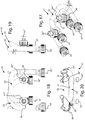
- the connecting assembly 1 is a single block realized with any technology available, for example by 3D printing, traditional molding of any type, etc.
- a chamber 2 is provided for hot water and a chamber 3 is provided for cold water.
- the hot water chamber 2 comprises an inlet 4' and an outlet 4" (which can be inverted with respect to the order shown in the figure, depending on the needs), provided with coupling systems, which do not constitute part of the present invention, and a single top fitting 4"' for the connection with a hydraulic connection (not shown) of the hot water of the specific hydraulic-sanitary element (also not shown).
- the chamber 2 through the inlet 4' and the outlet 4", is connected, in series, to the pipes of the loop circuit for hot water.
- the inlet 4' and the outlet 4" are mutually arranged side by side along the same side as the connecting assembly 1, i.e. with the axis parallel to each other, and all lying in a single plane of connection to the loop circuit.
- the top fitting 4"' has an axis orthogonal to the plane of connection to the loop circuit.
- the cold water chamber 3 comprises an inlet 5' and an outlet 5" (which can be inverted with respect to the order shown in the figure, depending on the needs), provided with coupling systems, which do not constitute part of the present invention, and a single top fitting 5"' for the connection to a hydraulic connection (not shown) of the cold water of the specific hydraulic-sanitary element (also not shown).
- the chamber 3, through the inlet 5' and the outlet 5", is connected, in series, to the pipes of the loop circuit for the cold water.
- the inlet 5' and the outlet 5" are mutually arranged side by side along the same side as the connecting assembly 1, i.e. with the axis parallel to each other, and all lying in a single plane of connection to the loop circuit.
- the top fitting 5"' has an axis orthogonal to the plane of connection to the loop circuit.
- all of the inlets 4', 5' and all of the outlets 4", 5" are mutually arranged side by side along the same side as the connecting assembly 1, i.e. with the axis parallel to each other, and all lying in a single plane of connection to the loop circuit.
- the fittings 4"' and 5"' for supplying hot and cold water to the hydraulic-sanitary element are preferably placed on the same face as the connecting assembly 1.
- a thread 6 is further provided on connecting assembly 1 to attach the collar supporting the discharge fitting.
- isolation chamber realized between the hot water chamber 2 and the cold water chamber 3, is indicated with numerical reference 7.
- the substantial difference with respect to the embodiment of figures 1 - 5 lies in the dimensions of the wheelbase (150 mm in the first embodiment and 80 mm in the second embodiment) (but, as said, the dimensions do not constitute a limitation of the protective scope of the invention in any way), and in that in this case the thread 6 is not present.
- the two chambers 2, 3 are, indeed, present as chambers 22 for hot water and 23 for cold water, but they are configured, again in the connecting assembly 21, as pipes 22, 23 respectively, separated from each other in the central section by an isolation space 27.
- the two chambers 2, 3 are, indeed, present as chambers 32 for hot water and 33 for cold water, but they are configured, again in the connecting assembly 31, as pipes 32, 33 respectively.
- the two chambers 32, 33 are joined by at least one fastening element 36, in the embodiment shown two fastening elements, which are stably constrained to the two pipes 32, 33 close to the ends.
- the substantial difference with respect to the embodiment of figures 11 - 16 lies in the fact that despite being set mutually side by side on the connection plane with the axis parallel to each other, the inlets 34', 35' and the outlets 34", 35" are offset in pairs and arranged alternately between the hot water chamber 32 and the cold water chamber 33.
- the hot water inlet 34' is flanked by the cold water inlet 35', flanked, in turn, by the hot water outlet 34", which is finally flanked, at the opposite end, by the cold water outlet 35".
- the hot water inlet 34' and the cold water outlet 35", set at the opposite ends of the connecting assembly 31, are placed in a more advanced position on the connection plane with respect to the hot water inlet 35' and to the cold water outlet 34", positioned between them.
- connection plane of the terminal ends of the two chambers 32, 33 allows a reduction in the wheelbase, making the connecting assembly significantly more compact.
- the chambers are partially mutually overlapping on the plane orthogonal to the connection plane, while maintaining an isolation space 37.
- connections of the various embodiments of the connecting assembly 1, 11, 21, 31 according to the invention can be formed by any type of coupling, for example, of the threaded, crimped, quick coupling type, by welding, etc.
Landscapes
- Engineering & Computer Science (AREA)
- General Engineering & Computer Science (AREA)
- Mechanical Engineering (AREA)
- Physics & Mathematics (AREA)
- Thermal Sciences (AREA)
- Chemical & Material Sciences (AREA)
- Combustion & Propulsion (AREA)
- Health & Medical Sciences (AREA)
- Life Sciences & Earth Sciences (AREA)
- Hydrology & Water Resources (AREA)
- Public Health (AREA)
- Water Supply & Treatment (AREA)
- Domestic Plumbing Installations (AREA)
- Lubricants (AREA)
Applications Claiming Priority (1)
| Application Number | Priority Date | Filing Date | Title |
|---|---|---|---|
| IT102018000007822A IT201800007822A1 (it) | 2018-08-03 | 2018-08-03 | Blocco per utenze idraulico-sanitarie |
Publications (1)
| Publication Number | Publication Date |
|---|---|
| EP3604699A1 true EP3604699A1 (fr) | 2020-02-05 |
Family
ID=64049559
Family Applications (1)
| Application Number | Title | Priority Date | Filing Date |
|---|---|---|---|
| EP19187999.8A Withdrawn EP3604699A1 (fr) | 2018-08-03 | 2019-07-24 | Assemblage connectant pour des installations hydrauliques-sanitaires |
Country Status (3)
| Country | Link |
|---|---|
| US (1) | US20200041059A1 (fr) |
| EP (1) | EP3604699A1 (fr) |
| IT (1) | IT201800007822A1 (fr) |
Families Citing this family (3)
| Publication number | Priority date | Publication date | Assignee | Title |
|---|---|---|---|---|
| US12553560B2 (en) * | 2021-06-30 | 2026-02-17 | Tim O'Connor | Mixing valve adapter |
| CN218562497U (zh) * | 2022-09-15 | 2023-03-03 | 上海科勒电子科技有限公司 | 一种座便器中的水路安装结构 |
| CN115493012B (zh) * | 2022-09-29 | 2026-03-03 | 浙江吉利控股集团有限公司 | 车用管路安装头、管路结构及车辆 |
Citations (5)
| Publication number | Priority date | Publication date | Assignee | Title |
|---|---|---|---|---|
| DE2812698B1 (de) * | 1978-03-23 | 1979-08-30 | Ludger Borgmann | Rohrverteiler fuer Zentralheizungsanlagen |
| EP0071870A2 (fr) * | 1981-08-12 | 1983-02-16 | Maile + Grammer GmbH | Distributeur de fluide pour chauffage urbain |
| IT1290251B1 (it) | 1997-02-04 | 1998-10-22 | Roberto Libani | Modulo edilizio prefabbricato per l'installazione di componenti idraulici-sanitari |
| EP1099896A2 (fr) * | 1999-11-10 | 2001-05-16 | Georg Fischer Haustechnik AG | Dispositif de connexion pour des conduits de fluide |
| DE202016107042U1 (de) * | 2016-12-16 | 2018-03-19 | Rehau Ag + Co | Fluidverteiler-Montageanordnung |
-
2018
- 2018-08-03 IT IT102018000007822A patent/IT201800007822A1/it unknown
-
2019
- 2019-07-24 EP EP19187999.8A patent/EP3604699A1/fr not_active Withdrawn
- 2019-07-30 US US16/526,148 patent/US20200041059A1/en not_active Abandoned
Patent Citations (5)
| Publication number | Priority date | Publication date | Assignee | Title |
|---|---|---|---|---|
| DE2812698B1 (de) * | 1978-03-23 | 1979-08-30 | Ludger Borgmann | Rohrverteiler fuer Zentralheizungsanlagen |
| EP0071870A2 (fr) * | 1981-08-12 | 1983-02-16 | Maile + Grammer GmbH | Distributeur de fluide pour chauffage urbain |
| IT1290251B1 (it) | 1997-02-04 | 1998-10-22 | Roberto Libani | Modulo edilizio prefabbricato per l'installazione di componenti idraulici-sanitari |
| EP1099896A2 (fr) * | 1999-11-10 | 2001-05-16 | Georg Fischer Haustechnik AG | Dispositif de connexion pour des conduits de fluide |
| DE202016107042U1 (de) * | 2016-12-16 | 2018-03-19 | Rehau Ag + Co | Fluidverteiler-Montageanordnung |
Also Published As
| Publication number | Publication date |
|---|---|
| US20200041059A1 (en) | 2020-02-06 |
| IT201800007822A1 (it) | 2020-02-03 |
Similar Documents
| Publication | Publication Date | Title |
|---|---|---|
| US20200041059A1 (en) | Connecting assembly for hydraulic-sanitary utilities | |
| ATE117415T1 (de) | Erweiterbarer verteiler für ein wasserversorgungssystem. | |
| US9574792B2 (en) | Modular manifold for a tankless water heater | |
| EP3181978B1 (fr) | Collecteur de couplage multiples pour raccords rapides | |
| CN110234924B (zh) | 接头及流体控制装置 | |
| MX2014008439A (es) | Medidor que tiene una chaqueta bandeada. | |
| ITMI20111020A1 (it) | Connettore multiplo e sistema per la miscelazione-erogazione di acqua sanitaria e depurata comprendente tale connettore multiplo | |
| CN102247761B (zh) | 用于具有一组至少一个过滤器盒的过滤装置的歧管 | |
| US20220397288A1 (en) | Manifold for the distribution of a fluid in a plumbing and heating system and relative distribution kit | |
| KR20160075046A (ko) | 정수기 | |
| US5567875A (en) | Modular gas meter assembly and associated manifold | |
| CN107673427A (zh) | 集成水路板及水处理设备 | |
| HUT74794A (en) | Panel heating radiator | |
| EP1972857A2 (fr) | Collecteur modulaire et coplanaire | |
| JP6518501B2 (ja) | 流体制御装置用継手、流体制御装置用開閉弁および流体制御装置 | |
| EP1405955A3 (fr) | Dispositif de distribution d'eau dans des systèmes sanitaires | |
| CN103255806A (zh) | 车间集中循环供水系统 | |
| NL2013156B1 (en) | A multi-part concentric manifold and method of making the manifold. | |
| CN108474499B (zh) | 通用液压连接系统 | |
| EP1938019A1 (fr) | Systeme de tubes capillaires | |
| PL219590B1 (pl) | Zespół rur i kształtek instalacji ciepłej i zimnej wody oraz instalacji centralnego ogrzewania | |
| US20090025921A1 (en) | Capillary Tube System | |
| IT202100021539A1 (it) | Impianto idraulico per la diffusione di acqua in una o più utenze | |
| ITPD20060123U1 (it) | Dispositivo perfezionato per il trattamento e la filtrazione dell'acqua | |
| CN110906592B (zh) | 电子膨胀阀 |
Legal Events
| Date | Code | Title | Description |
|---|---|---|---|
| PUAI | Public reference made under article 153(3) epc to a published international application that has entered the european phase |
Free format text: ORIGINAL CODE: 0009012 |
|
| STAA | Information on the status of an ep patent application or granted ep patent |
Free format text: STATUS: THE APPLICATION HAS BEEN PUBLISHED |
|
| AK | Designated contracting states |
Kind code of ref document: A1 Designated state(s): AL AT BE BG CH CY CZ DE DK EE ES FI FR GB GR HR HU IE IS IT LI LT LU LV MC MK MT NL NO PL PT RO RS SE SI SK SM TR |
|
| AX | Request for extension of the european patent |
Extension state: BA ME |
|
| STAA | Information on the status of an ep patent application or granted ep patent |
Free format text: STATUS: THE APPLICATION IS DEEMED TO BE WITHDRAWN |
|
| 18D | Application deemed to be withdrawn |
Effective date: 20200806 |