EP0071870A2 - Distributeur de fluide pour chauffage urbain - Google Patents
Distributeur de fluide pour chauffage urbain Download PDFInfo
- Publication number
- EP0071870A2 EP0071870A2 EP82106764A EP82106764A EP0071870A2 EP 0071870 A2 EP0071870 A2 EP 0071870A2 EP 82106764 A EP82106764 A EP 82106764A EP 82106764 A EP82106764 A EP 82106764A EP 0071870 A2 EP0071870 A2 EP 0071870A2
- Authority
- EP
- European Patent Office
- Prior art keywords
- chamber
- pipe distributor
- distributor according
- flow chamber
- return
- Prior art date
- Legal status (The legal status is an assumption and is not a legal conclusion. Google has not performed a legal analysis and makes no representation as to the accuracy of the status listed.)
- Withdrawn
Links
Images
Classifications
-
- F—MECHANICAL ENGINEERING; LIGHTING; HEATING; WEAPONS; BLASTING
- F24—HEATING; RANGES; VENTILATING
- F24D—DOMESTIC- OR SPACE-HEATING SYSTEMS, e.g. CENTRAL HEATING SYSTEMS; DOMESTIC HOT-WATER SUPPLY SYSTEMS; ELEMENTS OR COMPONENTS THEREFOR
- F24D3/00—Hot-water central heating systems
- F24D3/10—Feed-line arrangements, e.g. providing for heat-accumulator tanks, expansion tanks ; Hydraulic components of a central heating system
- F24D3/1058—Feed-line arrangements, e.g. providing for heat-accumulator tanks, expansion tanks ; Hydraulic components of a central heating system disposition of pipes and pipe connections
- F24D3/1066—Distributors for heating liquids
Definitions
- the invention relates to a pipe distributor with a flow chamber and a return chamber, which are arranged one above the other and are rectangular in cross section, in particular for district heating.
- Pipe distributors are used for heating systems and other piping systems. In heating systems, they are used to connect the supply lines and the return lines. They are also often used as heating circuit distributors for underfloor heating.
- a pipe distributor which consists of a flow chamber and a return chamber, to which several connecting pieces are connected.
- This known pipe distributor has a common horizontal partition that divides the pipe distributor into a flow chamber and a return chamber.
- the heat exchange that occurs in this pipe distributor between the flow chamber and the return chamber heats the heat transfer medium in the return chamber.
- heat transfer from the feed chamber to the return chamber should be largely avoided. This could be achieved in a simple manner in that these two chambers are arranged next to one another in a completely separate manner, as was previously customary in heating systems. At a Such an arrangement inevitably results in cumbersome, long cable runs which, on the one hand, entail energy losses and also represent a high cost of materials.
- the invention has for its object to provide a pipe distributor in which heat exchange between the flow chamber and the return chamber is largely avoided.
- the pipe distributor designed according to the invention takes up little space and prevents the heat transfer medium from heating up in the return chamber. Since flow temperatures of approx. 130 ° C occur in district heating systems and at the same time return temperatures of max. 50 ° C are to be maintained, the pipe distributor according to the invention is particularly suitable for use in district heating systems.
- the insulating layer consists of a rigid foam that mechanically connects the flow chamber and the return chamber.
- additional connecting means between the flow chamber and the return chamber can be dispensed with in most cases.
- additional connecting elements can be provided.
- the R ear manifold can be designed to achieve a higher mechanical stability so that one or more spacer elements are inserted into the intermediate space between the flow chamber and return chamber, via which the two chambers are mechanically interconnected.
- a particularly preferred embodiment provides that the pipe distributor has connecting pieces, of which at least one connecting piece (7) is passed through one of the chambers. This measure results in particularly favorable conditions for the connection of the return lines and supply lines. The result is a clear arrangement for the valves placed on the pipe distributor and long, lossy pipe branches are avoided.
- the pipe distributor according to the invention can furthermore be designed such that bushings are provided in one of the chambers, the inside diameter of which is larger than the outside diameter of the connecting pieces passed through it. In this way, heat exchange between the connecting pieces carried out and the chamber through which these connecting pieces are passed is avoided.
- the pipe distributor can be designed so that between there is a free space between the bushings and the connecting pieces.
- a further development provides that an insulating material is introduced into the intermediate space.
- This insulating material may contribute to an even firmer mechanical connection between the two chambers there is, must be used as without ß additional fasteners. Such a better mechanical connection results if the intermediate space is foamed with hard foam, for example.
- the pipe distributor can also be designed such that one or more centering elements are inserted between the bushing and the associated connecting pieces. These can be designed as rings which are placed on the connecting piece.
- a further development provides that ribs or other elevations are formed as centering elements on the connecting piece.
- centering elements are only necessary if, due to the design of the pipe distributor, centering without centering elements is not possible. This may be the case if there is only a very small space between the bushing and the connecting piece.
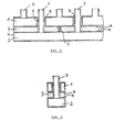
- the pipe distributor according to the invention shown in Fig. 1 consists essentially of a flow chamber 1, a return chamber 2 and an intermediate insulating layer 3.
- the two chambers 1, 2 are not only connected to each other by the insulating layer 3, but it is also an End plate 4 provided. Such an end plate can also be attached to the end, not shown in the drawing.
- spacer elements 5 can also be used, which are inserted at certain intervals between the two chambers 1 and 2.
- Such a spacer 5 is shown in the drawing, which can be welded or soldered to the flow chamber 1 and the return chamber 2.
- the insulating layer 3 can be glued to the opposite surfaces a and b.
- the space between the flow chamber 1 and the return chamber 2 is foamed by means of a rigid foam, which creates a sufficiently stable connection between the above-mentioned chambers 1 and 2 during hardening.
- connection pieces 6, 7 of the pipe distributor shown are attached so that they protrude on one side of the pipe distributor.
- connection piece 7, which lead to the return chamber 2, through the flow chamber 1 carried out.
- feedthroughs 8 are formed in the flow chamber 1, which have a larger inner diameter than the outer diameter of the connecting pieces 7 passed through them. A space thus arises between the connecting piece 7 and the leadthrough 8 This space can be free, so that there is no connection between the flow chamber 1 and the connecting piece 7.
- the intermediate space can also be filled with foam, as shown in FIG. 2.
- insulating layer 3 and the insulating material introduced between connecting piece 7 and flow chamber 1 can consist of hard foam, which is introduced in one operation by foaming.
- spacer elements 9 can be placed on the connecting piece 7.
- the spacer 9 consists of a ring placed on a connecting piece 7. This ring is preferably made of heat-insulating material.
- spacer elements are not shown in the drawing.
- Such spacer elements can also be ribs or other elevations formed on the connecting piece 7. It should only be ensured that these molded spacers rest on the inner wall of the bushing 8 with the smallest possible area in order to largely prevent heat transfer between the flow chamber 1 and the connecting piece 7.
Landscapes
- Engineering & Computer Science (AREA)
- Physics & Mathematics (AREA)
- Thermal Sciences (AREA)
- Chemical & Material Sciences (AREA)
- Combustion & Propulsion (AREA)
- Mechanical Engineering (AREA)
- General Engineering & Computer Science (AREA)
- Thermal Insulation (AREA)
- Steam Or Hot-Water Central Heating Systems (AREA)
Applications Claiming Priority (2)
| Application Number | Priority Date | Filing Date | Title |
|---|---|---|---|
| DE3131864 | 1981-08-12 | ||
| DE19813131864 DE3131864C1 (de) | 1981-08-12 | 1981-08-12 | Rohrverteiler fuer Fernheizungen |
Publications (2)
| Publication Number | Publication Date |
|---|---|
| EP0071870A2 true EP0071870A2 (fr) | 1983-02-16 |
| EP0071870A3 EP0071870A3 (fr) | 1983-07-06 |
Family
ID=6139167
Family Applications (1)
| Application Number | Title | Priority Date | Filing Date |
|---|---|---|---|
| EP82106764A Withdrawn EP0071870A3 (fr) | 1981-08-12 | 1982-07-27 | Distributeur de fluide pour chauffage urbain |
Country Status (2)
| Country | Link |
|---|---|
| EP (1) | EP0071870A3 (fr) |
| DE (1) | DE3131864C1 (fr) |
Cited By (3)
| Publication number | Priority date | Publication date | Assignee | Title |
|---|---|---|---|---|
| EP0898122A2 (fr) | 1997-08-20 | 1999-02-24 | Herbert Holzinger | Distributeur de circuit de chauffage |
| FR2855250A1 (fr) * | 2003-05-24 | 2004-11-26 | Danfoss As | Unite de vanne de chauffage |
| IT201800007822A1 (it) * | 2018-08-03 | 2020-02-03 | Nupi Ind Italiane Spa | Blocco per utenze idraulico-sanitarie |
Families Citing this family (1)
| Publication number | Priority date | Publication date | Assignee | Title |
|---|---|---|---|---|
| DE3514991A1 (de) * | 1985-04-25 | 1986-10-30 | Hans Dipl.-Ing.(FH) 7345 Deggingen Straub | Heizkreisverteiler mit zwei vollstaendig voneinander getrennten kammern |
Family Cites Families (7)
| Publication number | Priority date | Publication date | Assignee | Title |
|---|---|---|---|---|
| CH319341A (de) * | 1954-04-22 | 1957-02-15 | Sulzer Ag | In einem Futterrohr geführte, isolierte Leitung |
| GB1199493A (en) * | 1967-07-18 | 1970-07-22 | Heating And Ventilating Res As | Fluid Distributing Devices. |
| DE2116982C3 (de) * | 1971-04-07 | 1974-08-29 | Meinrad 7241 Ergenzingen Grammer | RohrleitungsVerteileranlage für Vor- und Rücklaufleitungen, insbesondere für Warmwasser-Heizungsanlagen |
| BE799809A (fr) * | 1972-06-02 | 1973-09-17 | Ctc Gmbh | Appareil repartiteur de fluide d'arrivee et collecteur de fluide de retour d'installations hydrauliques, |
| US4033381A (en) * | 1975-06-27 | 1977-07-05 | General Connectors Corporation | Hot air duct |
| DE2718932A1 (de) * | 1977-04-28 | 1978-11-02 | Hans Warzecha | Verteiler-sammler-vorrichtung |
| DE2812698C2 (de) * | 1978-03-23 | 1980-05-08 | Ludger 4400 Muenster Borgmann | Rohrverteiler für Zentralheizungsanlagen |
-
1981
- 1981-08-12 DE DE19813131864 patent/DE3131864C1/de not_active Expired
-
1982
- 1982-07-27 EP EP82106764A patent/EP0071870A3/fr not_active Withdrawn
Cited By (5)
| Publication number | Priority date | Publication date | Assignee | Title |
|---|---|---|---|---|
| EP0898122A2 (fr) | 1997-08-20 | 1999-02-24 | Herbert Holzinger | Distributeur de circuit de chauffage |
| FR2855250A1 (fr) * | 2003-05-24 | 2004-11-26 | Danfoss As | Unite de vanne de chauffage |
| CN100374783C (zh) * | 2003-05-24 | 2008-03-12 | 丹福斯有限公司 | 暖气阀单元 |
| IT201800007822A1 (it) * | 2018-08-03 | 2020-02-03 | Nupi Ind Italiane Spa | Blocco per utenze idraulico-sanitarie |
| EP3604699A1 (fr) * | 2018-08-03 | 2020-02-05 | NUPI INDUSTRIALE ITALIANE S.p.A. | Assemblage connectant pour des installations hydrauliques-sanitaires |
Also Published As
| Publication number | Publication date |
|---|---|
| EP0071870A3 (fr) | 1983-07-06 |
| DE3131864C1 (de) | 1983-02-24 |
Similar Documents
| Publication | Publication Date | Title |
|---|---|---|
| DE1911889C2 (de) | Plattenwärmetauscher | |
| EP0180086B1 (fr) | Refroidisseur d'huile | |
| DD150246A5 (de) | Waermetauschender bauteil fuer installationszwecke | |
| DE2722288A1 (de) | Plattenfoermiger verdampfer | |
| DE2404630C2 (de) | Wärmeaustauscher | |
| EP0071870A2 (fr) | Distributeur de fluide pour chauffage urbain | |
| EP0149090A1 (fr) | Isolation thermique | |
| DE1501235A1 (de) | Verfahren und Einrichtung zum Kuehlen einer Kammer | |
| DE19908683C2 (de) | Radiatorstruktur eines Satelliten | |
| DE10023949C1 (de) | Wärmetauscher, insbesondere Mikrostruktur-Wärmetauscher | |
| AT527068B1 (de) | Temperiervorrichtung für ein Batteriesystem mit einem Grundkörper und mehreren, in einem Strömungskanal angeordneten Lagerhülsen | |
| DE3109558A1 (de) | Waermetauscher zur kuehlung eines stroemungsmittels mit hoher temperatur | |
| DE2812698C2 (de) | Rohrverteiler für Zentralheizungsanlagen | |
| DE2513094A1 (de) | Elektrischer isolierstoffgehaeuse- heizkoerper | |
| WO2007042331A1 (fr) | Plaque d'echangeur thermique | |
| EP0139147A2 (fr) | Plancher double pour chauffage ou refroidissement | |
| CH675019A5 (fr) | ||
| DE29521278U1 (de) | Sonnenkollektor | |
| EP4198431A1 (fr) | Réservoir de liquide stationnaire | |
| DE830058C (de) | Vom Kuehlmittel durchflossener Bauteil fuer Gefrieranlagen | |
| DE8323129U1 (de) | Keramischer Wärmetauscher | |
| DE2512226A1 (de) | Sonnenkollektor | |
| EP0043960A2 (fr) | Radiateur à basse température | |
| DE2924305B1 (de) | Hohlplattenfoermiges Waermeaustauschelement | |
| DE1501235C (de) | Einrichtung zum Kühlen einer Kammer |
Legal Events
| Date | Code | Title | Description |
|---|---|---|---|
| PUAI | Public reference made under article 153(3) epc to a published international application that has entered the european phase |
Free format text: ORIGINAL CODE: 0009012 |
|
| AK | Designated contracting states |
Designated state(s): AT BE CH DE FR GB IT LI LU NL SE |
|
| PUAL | Search report despatched |
Free format text: ORIGINAL CODE: 0009013 |
|
| AK | Designated contracting states |
Designated state(s): AT BE CH DE FR GB IT LI LU NL SE |
|
| 17P | Request for examination filed |
Effective date: 19830803 |
|
| STAA | Information on the status of an ep patent application or granted ep patent |
Free format text: STATUS: THE APPLICATION HAS BEEN WITHDRAWN |
|
| 18W | Application withdrawn |
Withdrawal date: 19850524 |
|
| RIN1 | Information on inventor provided before grant (corrected) |
Inventor name: GRAMMER, MEINRAD |