EP3604720B1 - Système et procédé de fermeture motorisée - Google Patents
Système et procédé de fermeture motorisée Download PDFInfo
- Publication number
- EP3604720B1 EP3604720B1 EP18778239.6A EP18778239A EP3604720B1 EP 3604720 B1 EP3604720 B1 EP 3604720B1 EP 18778239 A EP18778239 A EP 18778239A EP 3604720 B1 EP3604720 B1 EP 3604720B1
- Authority
- EP
- European Patent Office
- Prior art keywords
- control module
- module
- sends
- enclosure
- signal
- Prior art date
- Legal status (The legal status is an assumption and is not a legal conclusion. Google has not performed a legal analysis and makes no representation as to the accuracy of the status listed.)
- Active
Links
Images


Classifications
-
- E—FIXED CONSTRUCTIONS
- E05—LOCKS; KEYS; WINDOW OR DOOR FITTINGS; SAFES
- E05D—HINGES OR SUSPENSION DEVICES FOR DOORS, WINDOWS OR WINGS
- E05D15/00—Suspension arrangements for wings
- E05D15/48—Suspension arrangements for wings allowing alternative movements
- E05D15/52—Suspension arrangements for wings allowing alternative movements for opening about a vertical as well as a horizontal axis
-
- E—FIXED CONSTRUCTIONS
- E05—LOCKS; KEYS; WINDOW OR DOOR FITTINGS; SAFES
- E05B—LOCKS; ACCESSORIES THEREFOR; HANDCUFFS
- E05B17/00—Accessories in connection with locks
- E05B17/0025—Devices for forcing the wing firmly against its seat or to initiate the opening of the wing
- E05B17/0029—Devices for forcing the wing firmly against its seat or to initiate the opening of the wing motor-operated
-
- E—FIXED CONSTRUCTIONS
- E05—LOCKS; KEYS; WINDOW OR DOOR FITTINGS; SAFES
- E05B—LOCKS; ACCESSORIES THEREFOR; HANDCUFFS
- E05B47/00—Operating or controlling locks or other fastening devices by electric or magnetic means
- E05B47/0001—Operating or controlling locks or other fastening devices by electric or magnetic means with electric actuators; Constructional features thereof
- E05B47/0012—Operating or controlling locks or other fastening devices by electric or magnetic means with electric actuators; Constructional features thereof with rotary electromotors
-
- E—FIXED CONSTRUCTIONS
- E05—LOCKS; KEYS; WINDOW OR DOOR FITTINGS; SAFES
- E05C—BOLTS OR FASTENING DEVICES FOR WINGS, SPECIALLY FOR DOORS OR WINDOWS
- E05C9/00—Arrangements of simultaneously actuated bolts or other securing devices at well-separated positions on the same wing
- E05C9/06—Arrangements of simultaneously actuated bolts or other securing devices at well-separated positions on the same wing with three or more sliding bars
- E05C9/063—Arrangements of simultaneously actuated bolts or other securing devices at well-separated positions on the same wing with three or more sliding bars extending along three or more sides of the wing or frame
- E05C9/066—Locks for windows or doors specially adapted for tilt and turn
-
- E—FIXED CONSTRUCTIONS
- E05—LOCKS; KEYS; WINDOW OR DOOR FITTINGS; SAFES
- E05D—HINGES OR SUSPENSION DEVICES FOR DOORS, WINDOWS OR WINGS
- E05D15/00—Suspension arrangements for wings
- E05D15/48—Suspension arrangements for wings allowing alternative movements
- E05D15/52—Suspension arrangements for wings allowing alternative movements for opening about a vertical as well as a horizontal axis
- E05D15/522—Suspension arrangements for wings allowing alternative movements for opening about a vertical as well as a horizontal axis with disconnecting means for the appropriate pivoting parts
- E05D15/523—Suspension arrangements for wings allowing alternative movements for opening about a vertical as well as a horizontal axis with disconnecting means for the appropriate pivoting parts using movable rods
- E05D15/524—Actuating mechanisms
-
- E—FIXED CONSTRUCTIONS
- E05—LOCKS; KEYS; WINDOW OR DOOR FITTINGS; SAFES
- E05F—DEVICES FOR MOVING WINGS INTO OPEN OR CLOSED POSITION; CHECKS FOR WINGS; WING FITTINGS NOT OTHERWISE PROVIDED FOR, CONCERNED WITH THE FUNCTIONING OF THE WING
- E05F15/00—Power-operated mechanisms for wings
- E05F15/60—Power-operated mechanisms for wings using electrical actuators
-
- E—FIXED CONSTRUCTIONS
- E05—LOCKS; KEYS; WINDOW OR DOOR FITTINGS; SAFES
- E05B—LOCKS; ACCESSORIES THEREFOR; HANDCUFFS
- E05B47/00—Operating or controlling locks or other fastening devices by electric or magnetic means
- E05B2047/0048—Circuits, feeding, monitoring
- E05B2047/0057—Feeding
- E05B2047/0058—Feeding by batteries
-
- E—FIXED CONSTRUCTIONS
- E05—LOCKS; KEYS; WINDOW OR DOOR FITTINGS; SAFES
- E05B—LOCKS; ACCESSORIES THEREFOR; HANDCUFFS
- E05B47/00—Operating or controlling locks or other fastening devices by electric or magnetic means
- E05B2047/0048—Circuits, feeding, monitoring
- E05B2047/0067—Monitoring
- E05B2047/0068—Door closed
-
- E—FIXED CONSTRUCTIONS
- E05—LOCKS; KEYS; WINDOW OR DOOR FITTINGS; SAFES
- E05F—DEVICES FOR MOVING WINGS INTO OPEN OR CLOSED POSITION; CHECKS FOR WINGS; WING FITTINGS NOT OTHERWISE PROVIDED FOR, CONCERNED WITH THE FUNCTIONING OF THE WING
- E05F15/00—Power-operated mechanisms for wings
- E05F15/70—Power-operated mechanisms for wings with automatic actuation
- E05F15/73—Power-operated mechanisms for wings with automatic actuation responsive to movement or presence of persons or objects
- E05F2015/765—Power-operated mechanisms for wings with automatic actuation responsive to movement or presence of persons or objects using optical sensors
-
- E—FIXED CONSTRUCTIONS
- E05—LOCKS; KEYS; WINDOW OR DOOR FITTINGS; SAFES
- E05Y—INDEXING SCHEME ASSOCIATED WITH SUBCLASSES E05D AND E05F, RELATING TO CONSTRUCTION ELEMENTS, ELECTRIC CONTROL, POWER SUPPLY, POWER SIGNAL OR TRANSMISSION, USER INTERFACES, MOUNTING OR COUPLING, DETAILS, ACCESSORIES, AUXILIARY OPERATIONS NOT OTHERWISE PROVIDED FOR, APPLICATION THEREOF
- E05Y2400/00—Electronic control; Electrical power; Power supply; Power or signal transmission; User interfaces
- E05Y2400/10—Electronic control
- E05Y2400/32—Position control, detection or monitoring
-
- E—FIXED CONSTRUCTIONS
- E05—LOCKS; KEYS; WINDOW OR DOOR FITTINGS; SAFES
- E05Y—INDEXING SCHEME ASSOCIATED WITH SUBCLASSES E05D AND E05F, RELATING TO CONSTRUCTION ELEMENTS, ELECTRIC CONTROL, POWER SUPPLY, POWER SIGNAL OR TRANSMISSION, USER INTERFACES, MOUNTING OR COUPLING, DETAILS, ACCESSORIES, AUXILIARY OPERATIONS NOT OTHERWISE PROVIDED FOR, APPLICATION THEREOF
- E05Y2600/00—Mounting or coupling arrangements for elements provided for in this subclass
- E05Y2600/40—Mounting location; Visibility of the elements
- E05Y2600/46—Mounting location; Visibility of the elements in or on the wing
Definitions
- This invention relates to a motorised closure system, specifically intended for enclosures formed by glazed surfaces, practicable opening, tilt-and-turn and sliding, in which the whole of the enclosure is constituted by continuous, flat surfaces without handles or protrusions with the carpentry seen or hidden, the entire system being managed by a control module in connection with a series of sensors, allowing the opening mode desired by the user, and also managing to respect the water-tightness of the enclosure.
- this invention defines an opening and closure method based on a system whose characteristics are like those of the previous motorised closure system.
- the field of application of this invention is the industrial sector related to the production, distribution and marketing of enclosure systems, mainly the sector related to windows, and more specifically with tilt-and-turn and sliding windows.
- Enclosure systems are known, not only in the industrial sector of manufacturers, distributors and traders of this type of enclosures, but also to the general public.
- conventional enclosures are constituted by a side frame that has a system that allows an axis of rotation alternative to the conventional swing, so the closure and opening system consists of a crank with which you can choose to open the window around a horizontal or vertical axis, or in any case by a sliding or slide movement.
- DE102010056352 the communication between the evaluation unit and the closure is done internally by the door body, and there is no means of controlling whether the door is open or closed, which does not solve the problem of security, since although it analyses if there is permission, it does not guarantee closure after opening, it does not have any sensor that ensures the closure, nor does it solve the problems in the comfort and water-tightness of the room where the door is placed.
- the means of this invention differ from those of DE102010058352 and the application of said means is incompatible between both enclosures.
- Document EP 0 537 805 A2 discloses a further example of a motorized closure system for a tilt-and-turn window.
- cranks and actuation elements can be dispensed with and the technical problem related to the breakages of manual elements such as conventional handles or cranks for this type of enclosures, whether doors or windows, resolves the security problem derived from said breaks and presents the improvements that an autonomous detection system has, and allows the detection of the opening or closure situation of said enclosure which solves problems both security problems, comfort or water-tightness of the room where the enclosure is located.
- the document FR3013378A1 discloses a carpentry comprising a frame intended to be fixed on a masonry element and at least one leaf. It further comprises an intermediate frame on which each leaf is movably mounted, the intermediate frame being movably mounted on the frame.
- the joinery includes motorization means for acting on command on the position of the intermediate frame relative to the sleeping frame between a closed position, in which the intermediate frame is pressed against the frame, and an open position, in which the intermediate frame is spaced from the frame to allow air to pass between them, and locking means to hold the frame intermediate in the closed position.
- the joinery further comprises control means for controlling the motorization means and the locking means.
- the document EP1323885A2 discloses a method and apparatus for driving windows, doors or similar with at least a pivoting and tilting wing wherein when the hinge system is in the tilt-release position and an instruction is given to close the leaf (i.e. the door or window), closure is registered reliably in the following manner, before locking.
- the first actuator drive is operated by the control unit for a sufficient duration, until it transmits a signal indicating arrival at its second end position.
- the detector indicates that the leaf is closed. Only when the second actuator drive signals that it has reached its end position, is locking completed.
- An Independent claim is included for the corresponding motor-driven closure and locking equipment.
- the invention relates to a motorised closure system according to the features of claim 1.
- the motorised closure system is intended for enclosures, both doors and windows, in which the conventional fitting of a conventional window is transformed by an electronic system completed by an electro-mechanical system capable of transmitting he desire and will of the user to open or close the enclosure element, without physical contact with the enclosure and without the need for the system to require handles or cranks.
- an enclosure formed by continuous, flat surfaces with no protrusions, no entrances, or protrusions is obtained, leaving the actuation mechanisms like the rest of the transformed or hidden structural elements.
- the enclosure system in this invention comprises the conventional elements for this type of enclosures, such as perimeter and interior carpentry, made up of visible profiles that are fixed to the enclosure gap; these profiles may be of different materials such as PVC or aluminium; or systems of profiles or hidden carpentry, in which it is the leaf itself that hides the enclosure profiles or glass; the leaf itself or glass of the enclosure; the upper and lower brackets or compasses that allow movement with respect to the leaves and their profiles; and the plurality of bolted blocking or closure fittings, both in the form of a flat plate and in the form of a square; the characteristic elements of this new invention being:
- This sensor is connected to the control module and sends the appropriate signals when it detects the user;
- the invention can incorporate a displacement module for certain types of enclosures, connected to the control module and composed of a controller unit that receives the instructions from the control module, and has a reduction gear and a system actuation motor that can move a skate with which the leaf is displaced.
- the system operates as follows.
- the user activates the system by means of the passage of the hand, or another object, that allows the detection of the optical sensor of the window, thus generating the actuation order.
- Said detection derives in a signal or order that is transmitted to the control module.
- the control module receives the order and transmits to the motorised module the commissioning order, in such a way that it pushes the drive piece that uses the profile itself as a guide and that moves the logical manoeuvring fitting, which is connected to the rest of bolted closure elements linked along the perimeter of the enclosure profile.
- the control module sends to the motorised module an opening signal in swing mode, an opening of oscillating mode or an opening in slide/sliding mode. It should also be reemphasised that the magnetic sensor detects if the enclosure is in an open or closed position, so it also sends said signal to the control module, which once interpreted in the control module sends the corresponding instruction to the motorised module.
- the logical manoeuvring fitting is moved to a first enclave, so that the bulls of the closure elements are released, and at that time there is a pressure on the rubber bands located between the leaf and the frame that causes a relative displacement between the leaf and the frame enough to allow the leaf to be loose and open in rocker mode.
- the exposure time to the optical sensor is long enough for the motor to push the drive and logical manoeuvring fitting to the first enclave, and the optical sensor continues to send the signal of exposure to the control module which interprets that the desired opening mode is the oscillating mode, therefore it sends the order to the motorised module to continue working until the logical manoeuvring fitting is positioned in the second enclave.
- the control module interprets that the desired opening mode is the sliding mode, according to the structure of the enclosure itself, it sends the order to the displacement module and it moves the fitting or skate, in this case horizontally guided to a section of toothed belt located in the tread of each frame, said rail being anchored at its ends as a zipper, although this zipper can be replaced by a threaded rod that acts as an auger or spindle.
- the one that dispenses with the displacement module, the regulation of the opening of the enclosure, either in the tilt opening mode, in the swing opening mode, and even for the coupling for enclosures with sliding type displacement is through the manual action of the user.
- the enclosure for example, a window
- the necessary actuation for the closure it is such that the user You must proceed to move the leaf, closing the window, until it is housed in the frame.
- the magnetic sensor considers that the leaf is closed, and the start order of the manoeuvre motor is originated, in the reverse direction of the opening, and whose final effects are the movement of the bolts of the leaf in their places of accommodation in the frame, giving rise, derived from the geometry of them, a pressure of the sealing rubber of the enclosure.
- the magnetic sensor does not send a signal to the stopping motor, so the user can detect if there has been a fault in the closure of the enclosure, for example, a window.
- sequence of the different openings is programmed on the programmable motherboard and in conjunction with or through the optical sensor.
- the location of certain elements of the system may vary in their location, as well as the electrical connection.
- the stages follow with which the control module sends the instruction to the displacement module; the magnetic sensor checks that the enclosure is open and sends a signal to the control module; and the control module sends the stop instruction to the displacement module.
- the optical sensor does not detect the user; the magnetic sensor detects whether the enclosure is open or not; if the magnetic sensor detects that the enclosure is open, it sends a signal to the control module; the control module sends a stop instruction to the motor module; and therefore the enclosure is open in a swing or sliding mode depending on the configuration of the fitting and the carpentry of said enclosure.
- the optical sensor detects the user, the optical sensor sends a signal to the control module, the control module gives an order to the motorised module to proceed with the opening, the logical fitting arrives at the second enclave; the magnetic sensor sends a signal of whether the enclosure is open or not; the enclosure is open, the magnetic sensor sends a signal to the control module; the control module sends a stop instruction to the motor module; and the enclosure is open in oscillating mode.
- the procedure is just the reverse, and is based on positioning the leaf in the frame so that the magnetic sensor detects said opening position, and the control module send the instructions to the motorised module in the opposite direction to that of the opening.
- FIG. 1 is the representation of the preferred embodiment of the motorised closure system object of this invention.
- the tilt-and-turn window enclosure system is formed by the following elements:
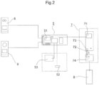
- FIG. 2 is a schematic representation of the interconnection between the different elements that make up the motorised system.
- the control module (5) is in connection with the optical sensor (6) and the magnetic sensor (9), so that it receives the signals from both sensors, interprets them thanks to the board programmable base (51) for the support of the system management electronics, which has a power supply (52) directly connected to the conventional power grid, and which has a secondary power supply (53); and how the instructions from the interpretation of the data made by the motherboard (51) are sent to the blocking module (7), where the control unit (71) that receives said instructions and interprets them to operate the multiplier (72) and the motor (73) of the system, which displaces the drive piece (74) and modifies the position of the logical manoeuvring hardware (8) to the corresponding enclave, depending on whether the movement of the final window is oscillating, swing or sliding.
- the sequence of the different openings is programmed on the programmable motherboard (51) and in conjunction with the optical sensor
- Figure 3 is a representation of another embodiment of the invention, in which a window that is also oscillating-swing has its elements configured in a different position, such as that the control module (5) is located in the lower horizontal profile of the perimeter carpentry (1), or that the blocking module (7) is in the upper horizontal profile of the internal carpentry (2) of the window alongside the logical manoeuvring fitting (8), but which in this case incorporates a displacement module (75), connected to a guide skate (78) which allows the motorised displacement of said leaf.
- a window that is also oscillating-swing has its elements configured in a different position, such as that the control module (5) is located in the lower horizontal profile of the perimeter carpentry (1), or that the blocking module (7) is in the upper horizontal profile of the internal carpentry (2) of the window alongside the logical manoeuvring fitting (8), but which in this case incorporates a displacement module (75), connected to a guide skate (78) which allows the motorised displacement of said leaf.
- Figure 4 is a representation of another embodiment of the invention, in this case a sliding or slide enclosure, which also has its elements configured in a different position from the previous embodiments, such as that the control module (5) is located in the upper horizontal profile of the perimeter carpentry (1), or that the blocking module (7) is in a lateral profile of the internal carpentry (2) of the window, while in this case it also incorporates a displacement module (75), connected which allows the motorised movement of the guided leaf along rails as a guide skate (78).
- the slide enclosure allows the movement of both leaves, therefore, this invention allows the system to be implemented in each leaf and therefore these previously highlighted elements are found in both sliding leaves.
- Figure 5 is a schematic representation of the interconnection between the different elements that form the motorised closure system for its second embodiment, which incorporates a displacement module (75), connected with the control module (5), and composed of a controller unit (751) that receives the instructions from the control module (5), and has a reduction gear (752) and a motor (753) connected to a guide skate (78) or guiding element with which it moves or move the leaf.
- a displacement module 75
- controller unit (751) that receives the instructions from the control module (5)
- a reduction gear 752
- a motor 753
- guide skate 78
Landscapes
- Engineering & Computer Science (AREA)
- Mechanical Engineering (AREA)
- Power-Operated Mechanisms For Wings (AREA)
- Operating, Guiding And Securing Of Roll- Type Closing Members (AREA)
- Casings For Electric Apparatus (AREA)
Claims (7)
- Système de fermeture motorisée destiné à des enceintes vitrées avec profils visibles ou invisibles, dont l'intégralité de l'enceinte est composée de surfaces planes et continues sans poignées, dotée de plusieurs fixations à boulons sous la forme d'une plaque plate vissée (41') et/ou d'un carré vissé (41) disposé le long de tout le périmètre de la charpenterie ou des profils de l'enceinte ; le système de fermeture motorisée étant composé des éléments suivants :un module de commande (5) composé d'une carte mère programmable (51) pour le soutien électronique de la gestion du système, alimenté électriquement et intégré à la charpenterie de l'enceinte ;au moins un capteur optique (6) permettant la réflexion de la lumière d'une diode d'émission à une diode de réception, connecté au module de commande (5) ;un module de blocage (7) connecté au module de commande (5), et composé d'une unité de commande (71) recevant les instructions du module de commande (5), d'un engrenage de réduction (72) et d'un moteur d'activation du système (73) ;une pièce d'entraînement (74) connectée au module de blocage (7), dont le déplacement est déterminé par le moteur d'activation du système (73) du module de blocage (7) ; laquelle pièce d'entraînement (74) étant connectée à une pièce de manoeuvre logique (8) et conçue pour modifier la position de la pièce de manoeuvre logique (8) vers une enclave correspondante en fonction du mouvement de la fenêtre (oscillation, balancement ou glissement) ;une pièce de manoeuvre logique (8) composée des éléments suivants :(a) une enclave destinée à l'action d'ouverture en mode de balancement, et une autre enclave destinée à l'action d'ouverture en mode d'oscillation ; ou(b) une enclave pour l'action de déplacement conformément aux directives en cas de glissement ou de mode de glissement ;laquelle pièce de manoeuvre logique (8) étant connectée à plusieurs fixations à boulons (41, 41'), de telle sorte que le mouvement de ladite pièce de manoeuvre logique (8) permette de déterminer l'état de fermeture ou de libération des fermetures ou des boulons ;au moins un capteur magnétique (9) configuré pour l'interprétation et la détection de l'état de fermeture de la fenêtre, lequel capteur magnétique (9) étant connecté au module de commande (5), lui-même connecté au module de blocage (7) de telle sorte que le module de commande (5) soit configuré pour interpréter le signal reçu par le capteur magnétique (9) et pour envoyer un ordre d'ouverture ou de fermeture au module de blocage (7) ;une connexion électrique-électronique (54) permettant une intercommunication des éléments précités et qui, grâce à sa centralisation dans le module de commande (5), est agencée en interne le long de la charpenterie et des profils de fermeture ; etoù, en fonction du délai d'exposition de l'utilisateur au capteur optique (6), le module de commande (5) envoie au module motorisé :un signal d'ouverture en mode de balancement, où la pièce de manoeuvre logique (8) se déplace vers la première enclave, de façon à libérer les boulons des éléments de fixation, et à appliquer en même temps une pression sur les joints toriques situés entre la feuille et le cadre, causant ainsi un déplacement relatif entre une feuille et un cadre, suffisant pour provoquer la libération de la feuille et l'ouverture en mode de balancement ; ouun signal d'ouverture en mode d'oscillation, où le délai d'exposition du capteur optique (6) est suffisant pour que le moteur (73) pousse la pièce d'entraînement (74) et la pièce de manoeuvre logique (8) vers la première enclave, et le capteur optique (6) continue d'envoyer le signal d'exposition au module de commande (5), tout en envoyant au module de blocage (7) l'ordre de continuer à fonctionner jusqu'à ce que la pièce de manoeuvre logique (8) soit positionnée dans la deuxième enclave ; ouun signal d'ouverture en mode de glissement, où un module de déplacement (75) est agencé pour permettre le mouvement motorisé d'une feuille guidée par des rails faisant office de patin de guidage (78) ; et où le module de déplacement (75) est connecté au module de commande (5) afin de recevoir des instructions, un tel module étant composé d'une unité de commande (751), d'un engrenage de réduction (752) et d'un moteur (753), le tout connecté au patin de guidage (78).
- Système de fermeture motorisé, selon les caractéristiques de la revendication 1, dont le module de commande (5) est connecté électriquement à une source d'alimentation électrique (52) directement branchée au réseau électrique conventionnel.
- Système de fermeture motorisé, selon les caractéristiques des revendications 1 et 3, dont le module de commande (5) est connecté électriquement à une source d'alimentation secondaire (53).
- Système de fermeture motorisé, selon les caractéristiques de la revendication 4, dont la source d'alimentation secondaire (53) est un accumulateur.
- Système de fermeture motorisé, selon les caractéristiques de la revendication 1, dont la séquence des différentes ouvertures de l'enceinte est programmée dans la carte mère programmable (51).
- Une méthode de fonctionnement d'un système de fermeture motorisé selon l'une des revendications 1 à 5, comprenant les étapes suivantes :le capteur optique (6) détecte l'utilisateur ;le capteur optique (6) envoie un signal de détection au module de commande (5), qui valide l'autorisation ;le module de commande (5) envoie un ordre d'ouverture au module de blocage (7) ;le module de blocage (7) déplace la pièce d'entraînement (74) ;la pièce d'entraînement (74) modifie la position de la pièce de manoeuvre logique (8) jusqu'à ce qu'elle atteigne la première enclave, modifiant ainsi l'emplacement des fixations à boulons (41, 41') de la charpenterie de l'enceinte ;le capteur optique (6) envoie un signal au module de commande (5) lui indiquant s'il a détecté ou non l'utilisateur, et envoie un signal au module de commande (5) ;le capteur magnétique (9) détecte la position de la fenêtre et envoie un signal au module de commande (5) ;le module de commande (5) analyse les signaux susmentionnés et envoie des instructions au module de blocage (7) ;la pièce d'entraînement (74) modifie la position de la pièce de manoeuvre logique (8) en fonction des indications du module de blocage (7), modifiant ainsi l'emplacement des fixations à boulons (41, 41') de la charpenterie de l'enceinte ;le capteur magnétique (9) détecte que la fenêtre est ouverte et envoie un signal au module de commande (5) ; etle module de commande (5) envoie un ordre d'arrêt au module de blocage (7) ;oùlorsque le capteur optique (6) ne détecte pas l'utilisateur ; le capteur magnétique (9) détecte si l'enceinte est ouverte ou non ; si le capteur magnétique (9) détecte que l'enceinte est ouverte, il envoie un signal au module de commande (5) ; le module de commande (5) envoie un ordre d'arrêt au module de blocage (7) ; et l'enceinte est donc ouverte en mode de balancement ou de glissement, selon la configuration de la pièce (8) et de la charpenterie de ladite enceinte ; etsi le capteur optique (6) détecte l'utilisateur, le capteur optique (6) envoie un signal au module de commande (5), le module de commande (5) donne un ordre d'ouverture au module de blocage (7), la pièce logique (8) arrive dans la seconde enclave ; le capteur magnétique (9) envoie un signal indiquant si l'enceinte est ouverte ou non ; l'enceinte est ouverte, le capteur magnétique (9) envoie un signal au module de commande (5) ; le module de commande (5) envoie un ordre d'arrêt au module de blocage (7) ; et l'enceinte est ouverte en mode d'oscillation ; etoù les étapes d'envoi de l'ordre d'arrêt au module de blocage (7) par le module de commande (5) sont déclenchées par l'envoi d'un ordre d'activation au module de déplacement (75) en mode de glissement, dans lequel le capteur magnétique (9) vérifie que l'enceinte est ouverte et envoie un message au module de commande (5), et le module de commande (5) envoie l'ordre d'arrêt au module de déplacement (75).
- La méthode de la revendication 6 où, pour la fermeture et le blocage du système, les étapes susmentionnées sont inversées.
Applications Claiming Priority (2)
| Application Number | Priority Date | Filing Date | Title |
|---|---|---|---|
| ES201700348A ES2694598B1 (es) | 2017-03-31 | 2017-03-31 | Sistema y método de cierre motorizado |
| PCT/ES2018/000041 WO2018178425A2 (fr) | 2017-03-31 | 2018-04-02 | Système et procédé de fermeture motorisée |
Publications (4)
| Publication Number | Publication Date |
|---|---|
| EP3604720A2 EP3604720A2 (fr) | 2020-02-05 |
| EP3604720A4 EP3604720A4 (fr) | 2020-04-01 |
| EP3604720C0 EP3604720C0 (fr) | 2024-07-17 |
| EP3604720B1 true EP3604720B1 (fr) | 2024-07-17 |
Family
ID=63674313
Family Applications (1)
| Application Number | Title | Priority Date | Filing Date |
|---|---|---|---|
| EP18778239.6A Active EP3604720B1 (fr) | 2017-03-31 | 2018-04-02 | Système et procédé de fermeture motorisée |
Country Status (3)
| Country | Link |
|---|---|
| EP (1) | EP3604720B1 (fr) |
| ES (2) | ES2694598B1 (fr) |
| WO (1) | WO2018178425A2 (fr) |
Families Citing this family (2)
| Publication number | Priority date | Publication date | Assignee | Title |
|---|---|---|---|---|
| WO2020216620A1 (fr) | 2019-04-24 | 2020-10-29 | Agc Glass Europe | Fenêtre et ensemble comprenant un châssis sans cadre exempt de poignée |
| CN116665359B (zh) * | 2023-07-31 | 2023-09-22 | 安徽云路交通信息技术有限公司 | 一种扩容性强的智能门禁装置及其门禁系统 |
Citations (1)
| Publication number | Priority date | Publication date | Assignee | Title |
|---|---|---|---|---|
| EP0537805A2 (fr) * | 1989-05-12 | 1993-04-21 | Aug. Winkhaus GmbH & Co. KG | Système de fenêtre pour un bâtiment |
Family Cites Families (18)
| Publication number | Priority date | Publication date | Assignee | Title |
|---|---|---|---|---|
| DE3844101A1 (de) * | 1988-12-28 | 1990-07-05 | Ludwig Kessler | Elektromechanische vorrichtung zum schliessen und oeffnen von fenstern |
| FR2740165A1 (fr) * | 1995-10-18 | 1997-04-25 | Blanchard Christian | Dispositif de verrouillage motorise pour portes |
| GB2310888A (en) * | 1996-03-09 | 1997-09-10 | Carr John Group Plc | Canopy window:remote operation |
| EP0822310B1 (fr) | 1996-08-01 | 2003-06-04 | GEZE GmbH | Porte glissante |
| JPH10136819A (ja) | 1996-11-08 | 1998-05-26 | Yoshihiro Kobayashi | Ledを利用した特定のペットだけが進入可能なドア |
| DE10105845A1 (de) * | 2001-02-07 | 2002-08-22 | Metall U Kunststoff Verarbeitu | Verschlusssystem und -vorrichtung |
| US20060005485A1 (en) * | 2001-05-22 | 2006-01-12 | Epps Jim C | Remotely controlled service window |
| DE10162972A1 (de) * | 2001-12-20 | 2003-07-10 | Esco Metallbaubeschlag Handel Gmbh | Motorische Stellvorrichtung für Fenster, Türen oder dergleichen mit zumindest einem Dreh/Kipp-Flügel |
| DE102004015147A1 (de) * | 2004-03-27 | 2005-10-13 | Aug. Winkhaus Gmbh & Co. Kg | Antriebseinrichtung |
| DE102004018066A1 (de) * | 2004-04-08 | 2005-10-27 | SCHÜCO International KG | Drehkippfenster |
| DE102005006313A1 (de) * | 2005-01-15 | 2006-07-27 | SCHÜCO International KG | Dreh-/Kippfenster mit elektromotorischem Antrieb mit Schubkette |
| KR100725959B1 (ko) | 2006-07-21 | 2007-06-11 | 삼성전자주식회사 | 하드디스크 드라이브 |
| BE1017949A5 (nl) | 2008-01-17 | 2010-01-12 | Parys Remi E Van | Beslag van een raam en onderdelen daarvoor. |
| DE102010056352B4 (de) | 2010-12-29 | 2025-04-30 | Carl Fuhr Gmbh & Co. Kg | Schließanlage für eine Tür eines Gebäudes |
| JP5912591B2 (ja) | 2012-02-01 | 2016-04-27 | 東京パーツ工業株式会社 | 物体検知装置及び車両用開閉体制御装置 |
| FR3013378B1 (fr) * | 2013-11-20 | 2015-12-04 | Univ Lorraine | Menuiserie telle qu'une fenetre ou une porte |
| EP3073034B1 (fr) * | 2015-03-23 | 2019-03-13 | VKR Holding A/S | Toit ouvrant manuellement et électriquement avec un élément de verrouillage actionnable manuellement et électriquement |
| ES2589835B1 (es) * | 2015-05-15 | 2017-09-07 | Cabañero, S.L. | Cerramiento practicable inteligente |
-
2017
- 2017-03-31 ES ES201700348A patent/ES2694598B1/es active Active
-
2018
- 2018-04-02 WO PCT/ES2018/000041 patent/WO2018178425A2/fr not_active Ceased
- 2018-04-02 EP EP18778239.6A patent/EP3604720B1/fr active Active
- 2018-04-02 ES ES18778239T patent/ES2986824T3/es active Active
Patent Citations (1)
| Publication number | Priority date | Publication date | Assignee | Title |
|---|---|---|---|---|
| EP0537805A2 (fr) * | 1989-05-12 | 1993-04-21 | Aug. Winkhaus GmbH & Co. KG | Système de fenêtre pour un bâtiment |
Also Published As
| Publication number | Publication date |
|---|---|
| ES2694598A1 (es) | 2018-12-21 |
| WO2018178425A3 (fr) | 2018-12-06 |
| WO2018178425A2 (fr) | 2018-10-04 |
| EP3604720A4 (fr) | 2020-04-01 |
| EP3604720C0 (fr) | 2024-07-17 |
| EP3604720A2 (fr) | 2020-02-05 |
| ES2694598B1 (es) | 2019-07-09 |
| ES2986824T3 (es) | 2024-11-12 |
Similar Documents
| Publication | Publication Date | Title |
|---|---|---|
| EP2545238B1 (fr) | Porte coulissante à grande ouverture | |
| US8627604B2 (en) | Bypass door | |
| US8844200B2 (en) | Electrical door operator | |
| EP2663722B1 (fr) | Système d'entraînement pour une porte coulissante automatique | |
| EP3144460B1 (fr) | Actionneur motorisé | |
| US8752870B2 (en) | Remote-controlled security bar | |
| US20090025296A1 (en) | Sliding door and window operating system | |
| US9062479B2 (en) | Remote-controlled security apparatus including a security bar | |
| US11225816B2 (en) | Sliding security door with passive deadlock prevention | |
| EP3604720B1 (fr) | Système et procédé de fermeture motorisée | |
| KR20190061623A (ko) | 자동 잠금 기능을 구비하는 창호 | |
| US10344523B2 (en) | Opposing door opener | |
| US20210222477A1 (en) | Parallel operation of door operators | |
| KR101918809B1 (ko) | 전자잠금장치와 개방유지장치를 구비한 반자동문 시스템 및 그 제어방법 | |
| EP2302151B1 (fr) | Système de porte coulissante et pivotante avec dispositif d'ouverture de secours | |
| KR20090098240A (ko) | 창문 개폐장치 | |
| JP2006125149A (ja) | 引き違いサッシ | |
| US20230295976A1 (en) | Lift gates and related control systems and methods | |
| EP2412902B1 (fr) | Porte sectionnelle avec porte d'entrée dotée d'un système de fermeture | |
| GB2486971A (en) | A floor mounted door actuator unit for swing door | |
| EP1722059B1 (fr) | Porte sectionnelle | |
| EP3623560B1 (fr) | Système de déplacement comprenant un système de verrouillage | |
| CH711553A1 (fr) | Dispositif d'ouverture et de fermeture de vantail, et porte ou fenêtre comportant un tel dispositif. | |
| JP2001280045A (ja) | 建築用電動シャッターにおける障害物検知装置 | |
| WO2000023682A1 (fr) | Mecanisme de manipulation d'une fenetre |
Legal Events
| Date | Code | Title | Description |
|---|---|---|---|
| STAA | Information on the status of an ep patent application or granted ep patent |
Free format text: STATUS: THE INTERNATIONAL PUBLICATION HAS BEEN MADE |
|
| PUAI | Public reference made under article 153(3) epc to a published international application that has entered the european phase |
Free format text: ORIGINAL CODE: 0009012 |
|
| STAA | Information on the status of an ep patent application or granted ep patent |
Free format text: STATUS: REQUEST FOR EXAMINATION WAS MADE |
|
| 17P | Request for examination filed |
Effective date: 20191001 |
|
| AK | Designated contracting states |
Kind code of ref document: A2 Designated state(s): AL AT BE BG CH CY CZ DE DK EE ES FI FR GB GR HR HU IE IS IT LI LT LU LV MC MK MT NL NO PL PT RO RS SE SI SK SM TR |
|
| AX | Request for extension of the european patent |
Extension state: BA ME |
|
| STAA | Information on the status of an ep patent application or granted ep patent |
Free format text: STATUS: EXAMINATION IS IN PROGRESS |
|
| A4 | Supplementary search report drawn up and despatched |
Effective date: 20200304 |
|
| RIC1 | Information provided on ipc code assigned before grant |
Ipc: E05D 15/06 20060101ALI20200227BHEP Ipc: E05F 15/60 20150101ALI20200227BHEP Ipc: E05B 47/00 20060101AFI20200227BHEP Ipc: E05D 15/524 20060101ALI20200227BHEP Ipc: E05C 9/06 20060101ALI20200227BHEP Ipc: E05B 17/00 20060101ALI20200227BHEP Ipc: E05D 15/52 20060101ALI20200227BHEP |
|
| 17Q | First examination report despatched |
Effective date: 20200401 |
|
| DAV | Request for validation of the european patent (deleted) | ||
| DAX | Request for extension of the european patent (deleted) | ||
| GRAP | Despatch of communication of intention to grant a patent |
Free format text: ORIGINAL CODE: EPIDOSNIGR1 |
|
| STAA | Information on the status of an ep patent application or granted ep patent |
Free format text: STATUS: GRANT OF PATENT IS INTENDED |
|
| INTG | Intention to grant announced |
Effective date: 20240410 |
|
| GRAS | Grant fee paid |
Free format text: ORIGINAL CODE: EPIDOSNIGR3 |
|
| GRAA | (expected) grant |
Free format text: ORIGINAL CODE: 0009210 |
|
| STAA | Information on the status of an ep patent application or granted ep patent |
Free format text: STATUS: THE PATENT HAS BEEN GRANTED |
|
| AK | Designated contracting states |
Kind code of ref document: B1 Designated state(s): AL AT BE BG CH CY CZ DE DK EE ES FI FR GB GR HR HU IE IS IT LI LT LU LV MC MK MT NL NO PL PT RO RS SE SI SK SM TR |
|
| REG | Reference to a national code |
Ref country code: CH Ref legal event code: EP |
|
| REG | Reference to a national code |
Ref country code: DE Ref legal event code: R096 Ref document number: 602018071890 Country of ref document: DE |
|
| REG | Reference to a national code |
Ref country code: IE Ref legal event code: FG4D |
|
| U01 | Request for unitary effect filed |
Effective date: 20240719 |
|
| U07 | Unitary effect registered |
Designated state(s): AT BE BG DE DK EE FI FR IT LT LU LV MT NL PT SE SI Effective date: 20240801 |
|
| REG | Reference to a national code |
Ref country code: ES Ref legal event code: FG2A Ref document number: 2986824 Country of ref document: ES Kind code of ref document: T3 Effective date: 20241112 |
|
| PG25 | Lapsed in a contracting state [announced via postgrant information from national office to epo] |
Ref country code: NO Free format text: LAPSE BECAUSE OF FAILURE TO SUBMIT A TRANSLATION OF THE DESCRIPTION OR TO PAY THE FEE WITHIN THE PRESCRIBED TIME-LIMIT Effective date: 20241017 |
|
| PG25 | Lapsed in a contracting state [announced via postgrant information from national office to epo] |
Ref country code: GR Free format text: LAPSE BECAUSE OF FAILURE TO SUBMIT A TRANSLATION OF THE DESCRIPTION OR TO PAY THE FEE WITHIN THE PRESCRIBED TIME-LIMIT Effective date: 20241018 Ref country code: PL Free format text: LAPSE BECAUSE OF FAILURE TO SUBMIT A TRANSLATION OF THE DESCRIPTION OR TO PAY THE FEE WITHIN THE PRESCRIBED TIME-LIMIT Effective date: 20240717 |
|
| PG25 | Lapsed in a contracting state [announced via postgrant information from national office to epo] |
Ref country code: IS Free format text: LAPSE BECAUSE OF FAILURE TO SUBMIT A TRANSLATION OF THE DESCRIPTION OR TO PAY THE FEE WITHIN THE PRESCRIBED TIME-LIMIT Effective date: 20241117 |
|
| PG25 | Lapsed in a contracting state [announced via postgrant information from national office to epo] |
Ref country code: HR Free format text: LAPSE BECAUSE OF FAILURE TO SUBMIT A TRANSLATION OF THE DESCRIPTION OR TO PAY THE FEE WITHIN THE PRESCRIBED TIME-LIMIT Effective date: 20240717 |
|
| PG25 | Lapsed in a contracting state [announced via postgrant information from national office to epo] |
Ref country code: RS Free format text: LAPSE BECAUSE OF FAILURE TO SUBMIT A TRANSLATION OF THE DESCRIPTION OR TO PAY THE FEE WITHIN THE PRESCRIBED TIME-LIMIT Effective date: 20241017 |
|
| PG25 | Lapsed in a contracting state [announced via postgrant information from national office to epo] |
Ref country code: RS Free format text: LAPSE BECAUSE OF FAILURE TO SUBMIT A TRANSLATION OF THE DESCRIPTION OR TO PAY THE FEE WITHIN THE PRESCRIBED TIME-LIMIT Effective date: 20241017 Ref country code: PL Free format text: LAPSE BECAUSE OF FAILURE TO SUBMIT A TRANSLATION OF THE DESCRIPTION OR TO PAY THE FEE WITHIN THE PRESCRIBED TIME-LIMIT Effective date: 20240717 Ref country code: NO Free format text: LAPSE BECAUSE OF FAILURE TO SUBMIT A TRANSLATION OF THE DESCRIPTION OR TO PAY THE FEE WITHIN THE PRESCRIBED TIME-LIMIT Effective date: 20241017 Ref country code: IS Free format text: LAPSE BECAUSE OF FAILURE TO SUBMIT A TRANSLATION OF THE DESCRIPTION OR TO PAY THE FEE WITHIN THE PRESCRIBED TIME-LIMIT Effective date: 20241117 Ref country code: HR Free format text: LAPSE BECAUSE OF FAILURE TO SUBMIT A TRANSLATION OF THE DESCRIPTION OR TO PAY THE FEE WITHIN THE PRESCRIBED TIME-LIMIT Effective date: 20240717 Ref country code: GR Free format text: LAPSE BECAUSE OF FAILURE TO SUBMIT A TRANSLATION OF THE DESCRIPTION OR TO PAY THE FEE WITHIN THE PRESCRIBED TIME-LIMIT Effective date: 20241018 |
|
| PG25 | Lapsed in a contracting state [announced via postgrant information from national office to epo] |
Ref country code: SM Free format text: LAPSE BECAUSE OF FAILURE TO SUBMIT A TRANSLATION OF THE DESCRIPTION OR TO PAY THE FEE WITHIN THE PRESCRIBED TIME-LIMIT Effective date: 20240717 |
|
| PG25 | Lapsed in a contracting state [announced via postgrant information from national office to epo] |
Ref country code: CZ Free format text: LAPSE BECAUSE OF FAILURE TO SUBMIT A TRANSLATION OF THE DESCRIPTION OR TO PAY THE FEE WITHIN THE PRESCRIBED TIME-LIMIT Effective date: 20240717 |
|
| PG25 | Lapsed in a contracting state [announced via postgrant information from national office to epo] |
Ref country code: SK Free format text: LAPSE BECAUSE OF FAILURE TO SUBMIT A TRANSLATION OF THE DESCRIPTION OR TO PAY THE FEE WITHIN THE PRESCRIBED TIME-LIMIT Effective date: 20240717 |
|
| U20 | Renewal fee for the european patent with unitary effect paid |
Year of fee payment: 8 Effective date: 20250326 |
|
| PLBE | No opposition filed within time limit |
Free format text: ORIGINAL CODE: 0009261 |
|
| STAA | Information on the status of an ep patent application or granted ep patent |
Free format text: STATUS: NO OPPOSITION FILED WITHIN TIME LIMIT |
|
| 26N | No opposition filed |
Effective date: 20250422 |
|
| PGFP | Annual fee paid to national office [announced via postgrant information from national office to epo] |
Ref country code: ES Payment date: 20250502 Year of fee payment: 8 |
|
| REG | Reference to a national code |
Ref country code: CH Ref legal event code: H13 Free format text: ST27 STATUS EVENT CODE: U-0-0-H10-H13 (AS PROVIDED BY THE NATIONAL OFFICE) Effective date: 20251125 |
|
| PG25 | Lapsed in a contracting state [announced via postgrant information from national office to epo] |
Ref country code: MC Free format text: LAPSE BECAUSE OF FAILURE TO SUBMIT A TRANSLATION OF THE DESCRIPTION OR TO PAY THE FEE WITHIN THE PRESCRIBED TIME-LIMIT Effective date: 20240717 |
|
| GBPC | Gb: european patent ceased through non-payment of renewal fee |
Effective date: 20250402 |
|
| PG25 | Lapsed in a contracting state [announced via postgrant information from national office to epo] |
Ref country code: GB Free format text: LAPSE BECAUSE OF NON-PAYMENT OF DUE FEES Effective date: 20250402 |
|
| PG25 | Lapsed in a contracting state [announced via postgrant information from national office to epo] |
Ref country code: CH Free format text: LAPSE BECAUSE OF NON-PAYMENT OF DUE FEES Effective date: 20250430 |
|
| PG25 | Lapsed in a contracting state [announced via postgrant information from national office to epo] |
Ref country code: IE Free format text: LAPSE BECAUSE OF NON-PAYMENT OF DUE FEES Effective date: 20250402 |
|
| PG25 | Lapsed in a contracting state [announced via postgrant information from national office to epo] |
Ref country code: RO Free format text: LAPSE BECAUSE OF FAILURE TO SUBMIT A TRANSLATION OF THE DESCRIPTION OR TO PAY THE FEE WITHIN THE PRESCRIBED TIME-LIMIT Effective date: 20240717 |