EP3604881A1 - Schraubverbindung für stahlrohre - Google Patents
Schraubverbindung für stahlrohre Download PDFInfo
- Publication number
- EP3604881A1 EP3604881A1 EP18774281.2A EP18774281A EP3604881A1 EP 3604881 A1 EP3604881 A1 EP 3604881A1 EP 18774281 A EP18774281 A EP 18774281A EP 3604881 A1 EP3604881 A1 EP 3604881A1
- Authority
- EP
- European Patent Office
- Prior art keywords
- male thread
- thread
- stabbing flank
- pin
- female thread
- Prior art date
- Legal status (The legal status is an assumption and is not a legal conclusion. Google has not performed a legal analysis and makes no representation as to the accuracy of the status listed.)
- Granted
Links
Images







Classifications
-
- F—MECHANICAL ENGINEERING; LIGHTING; HEATING; WEAPONS; BLASTING
- F16—ENGINEERING ELEMENTS AND UNITS; GENERAL MEASURES FOR PRODUCING AND MAINTAINING EFFECTIVE FUNCTIONING OF MACHINES OR INSTALLATIONS; THERMAL INSULATION IN GENERAL
- F16L—PIPES; JOINTS OR FITTINGS FOR PIPES; SUPPORTS FOR PIPES, CABLES OR PROTECTIVE TUBING; MEANS FOR THERMAL INSULATION IN GENERAL
- F16L15/00—Screw-threaded joints; Forms of screw-threads for such joints
- F16L15/001—Screw-threaded joints; Forms of screw-threads for such joints with conical threads
- F16L15/004—Screw-threaded joints; Forms of screw-threads for such joints with conical threads with axial sealings having at least one plastically deformable sealing surface
-
- F—MECHANICAL ENGINEERING; LIGHTING; HEATING; WEAPONS; BLASTING
- F16—ENGINEERING ELEMENTS AND UNITS; GENERAL MEASURES FOR PRODUCING AND MAINTAINING EFFECTIVE FUNCTIONING OF MACHINES OR INSTALLATIONS; THERMAL INSULATION IN GENERAL
- F16L—PIPES; JOINTS OR FITTINGS FOR PIPES; SUPPORTS FOR PIPES, CABLES OR PROTECTIVE TUBING; MEANS FOR THERMAL INSULATION IN GENERAL
- F16L15/00—Screw-threaded joints; Forms of screw-threads for such joints
- F16L15/04—Screw-threaded joints; Forms of screw-threads for such joints with additional sealings
-
- F—MECHANICAL ENGINEERING; LIGHTING; HEATING; WEAPONS; BLASTING
- F16—ENGINEERING ELEMENTS AND UNITS; GENERAL MEASURES FOR PRODUCING AND MAINTAINING EFFECTIVE FUNCTIONING OF MACHINES OR INSTALLATIONS; THERMAL INSULATION IN GENERAL
- F16L—PIPES; JOINTS OR FITTINGS FOR PIPES; SUPPORTS FOR PIPES, CABLES OR PROTECTIVE TUBING; MEANS FOR THERMAL INSULATION IN GENERAL
- F16L15/00—Screw-threaded joints; Forms of screw-threads for such joints
- F16L15/06—Screw-threaded joints; Forms of screw-threads for such joints characterised by the shape of the screw-thread
-
- E—FIXED CONSTRUCTIONS
- E21—EARTH OR ROCK DRILLING; MINING
- E21B—EARTH OR ROCK DRILLING; OBTAINING OIL, GAS, WATER, SOLUBLE OR MELTABLE MATERIALS OR A SLURRY OF MINERALS FROM WELLS
- E21B17/00—Drilling rods or pipes; Flexible drill strings; Kellies; Drill collars; Sucker rods; Cables; Casings; Tubings
- E21B17/02—Couplings; joints
- E21B17/04—Couplings; joints between rod or the like and bit or between rod and rod or the like
- E21B17/042—Threaded
Definitions
- the present disclosure relates to a threaded connection for steel pipe, and more particularly, to a threaded connection for connecting two steel pipes to each other.
- a Steel pipes called oil country tubular goods are used, for example, for prospecting and producing oil or natural gas in oil wells or natural gas wells (hereinafter collectively referred to as "oil well"), developing non-conventional resources such as oil sand or shale gas, retrieving or storing carbon dioxide (Carbon dioxide Capture and Storage (CCS)), geothermal power generation, or in hot springs.
- oil well oil wells or natural gas wells
- non-conventional resources such as oil sand or shale gas
- CCS Carbon dioxide Capture and Storage
- a threaded connection is used to connect steel pipes.
- a coupling-type connection connects a pair of pipes, one of which is a steel pipe and the other one is a coupling.
- a male thread is provided on the outer periphery of each of the ends of the steel pipe, while a female thread is provided on the inner periphery of each of the ends of the coupling. Then, the male thread of the steel pipe is screwed onto the female thread of the coupling such that they are made up and connected.
- An integral-type connection connects a pair of pipes that are both steel pipes, and does not use a separate coupling.
- a male thread is provided on the outer periphery of one end of each steel pipe, while a female thread is provided on the inner periphery of the other end. Then, the male thread of one steel pipe is screwed onto the female thread of the other steel pipe such that they are made up and connected.
- a connection portion of a pipe end on which a male thread is provided includes an element to be inserted into a female thread, and thus is usually referred to as "pin”.
- a connection portion of a pipe end on which a female thread is provided includes an element for receiving a male thread, and thus is referred to as "box”.
- a pin and a box constitute ends of pipes and are thus tubular in shape.
- An oil well is drilled along while its side wall is reinforced by oil country tubular goods to prevent the side wall from collapsing during drilling, which results in multiple oil country tubular goods arranged in one another.
- both land and offshore wells have become deeper and deeper; in such environments, threaded connections in which the inner and outer diameters of the connection portions are generally the same as, or slightly larger than, the inner and outer diameters of the steel pipes are often used to connect oil country tubular goods, in order to develop oil wells efficiently.
- the use of such threaded connections minimizes the gaps between the oil country tubular goods arranged in one another, making it possible to efficiently develop a deep oil well without significantly increasing the diameter of the well.
- a threaded connection is required to have good sealing performance against a pressure fluid from the inside (hereinafter also referred to as "internal pressure") and a pressure fluid from the outside (hereinafter also referred to as “external pressure”) under the above-described restrictions on the inner and outer diameters. Further, if oil country tubular goods are used in an oil well with great depth, for example, thermal expansion thereof may apply large tensile loads or compression loads to the threaded connections. In such environments, too, a threaded connection is required to have good sealing performance.
- Known threaded connections that ensure sealing performance include those having a seal that uses a metal-to-metal contact (hereinafter referred to as "metal seal”).
- metal seal the diameter of the sealing surface of the pin is slightly larger than the diameter of the sealing surface of the box (this difference in diameter will be referred to as “amount of interference”); when the threaded connection is made up and the sealing surfaces are made to fit together, the amount of interference reduces the diameter of the sealing surface of the pin while increasing the diameter of the sealing surface of the box; these sealing surfaces try to return to their respective original diameters, providing an elastic recovery which produces contact pressures on the sealing surfaces such that their entire peripheries adhere to each other, thereby providing sealing performance.
- threaded connections that ensure sealing performance include those that, instead of or in addition to the use of a metal seal, provides sealing performance using the threaded assembly. More specifically, in a region of the made-up threaded assembly with a predetermined length or longer, the clearance between the thread surfaces of the pin and box is small and a viscous lubricant called dope is provided in this clearance, and the interference between the thread diameters of the pin and box produces contact surface pressures (this construction will be hereinafter referred to as "thread seal (construction)" on the thread surfaces. Threaded connections are also known that have such thread seals to provide sealing performance against the internal and external pressures.
- JP H08(1996)-303657 A states: "To facilitate introduction and removal of tools, it is preferable that the engaging flank or stabbing flank of a tooth of the male thread has an angle with a larger absolute value. This angle, relative to a plane perpendicular to the axis of the thread, may be about 10 ° to 45 °, for example. To help introduce the male element into the female housing without damaging a thread due to catching, it is preferable to provide an engaging flank with a certain angle in a maximum-diameter portion connected to the tip of a tooth of the male thread.
- the angle relative to a plane perpendicular to the axis of the thread is between 30 ° and 70 °.”
- JP H08(1996)-303657 A has good performance.
- the present inventors found out that further improvements would be possible in terms of the ability to prevent cross-threading and the performance exhibited when compression loads are being applied, as discussed further below.
- An object of the present disclosure is to provide a threaded connection for steel pipe that prevents cross-threading and provides good compression load resistance.
- a threaded connection for steel pipe includes a tubular pin and a tubular box.
- the pin is located on one end of the steel pipe.
- the pin is inserted into the box such that the box and pin are made up.
- the pin includes a male thread.
- the male thread is provided on an outer periphery of the pin.
- the box includes a female thread.
- the female thread corresponds to the male thread and is provided on an inner periphery of the box.
- the male thread and the female thread are trapezoidal threads and tapered threads.
- the male thread includes a male thread crest, a male thread root, a male thread stabbing flank, and a male thread load flank.
- the male thread stabbing flank is located closer to a tip of the pin.
- the male thread load flank is located farther from the tip of the pin.
- the male thread stabbing flank includes a first male thread stabbing flank portion and a second male thread stabbing flank portion.
- the first male thread stabbing flank portion is located farther from a pipe axis of the steel pipe and has a stabbing flank angle of -10 to 15 degrees.
- the second male thread stabbing flank portion is located closer to the pipe axis and has a stabbing flank angle of 20 to 60 degrees.
- the second male thread stabbing flank portion has a height of 20 to 60 % of that of the male thread.
- the female thread includes a female thread crest, a female thread root, a female thread stabbing flank, and a female thread load flank.
- the female thread crest faces the male thread root.
- the female thread root faces the male thread crest.
- the female thread stabbing flank faces the male thread stabbing flank.
- the female thread load flank faces the male thread load flank.
- the female thread stabbing flank includes a first female thread stabbing flank portion and a second female thread stabbing flank portion.
- the first female thread stabbing flank portion is located farther from the pipe axis and has a stabbing flank angle equal to the stabbing flank angle of the first male thread stabbing flank portion.
- the second female thread stabbing flank portion is located closer to the pipe axis and has a stabbing flank angle equal to the stabbing flank angle of the second male thread stabbing flank portion.
- a threaded connection for steel pipe is a threaded connection for connecting two steel pipes to each other.
- the present threaded connection includes a tubular pin and a tubular box.
- the pin is located on one end of the steel pipe.
- the pin is inserted into the box such that the box and pin are made up.
- the pin includes a male thread.
- the male thread is provided on an outer periphery of the pin.
- the box includes a female thread.
- the female thread corresponds to the male thread and is provided on an inner periphery of the box.
- the male thread and the female thread are trapezoidal threads and tapered threads.
- the male thread includes a male thread crest, a male thread root, a male thread stabbing flank, and a male thread load flank.
- the male thread stabbing flank is located closer to a tip of the pin.
- the male thread load flank is located farther from the tip of the pin.
- the male thread stabbing flank includes a first male thread stabbing flank portion and a second male thread stabbing flank portion.
- the first male thread stabbing flank portion is located farther from a pipe axis of the steel pipe and has a stabbing flank angle of -10 to 15 degrees.
- the second male thread stabbing flank portion is located closer to the pipe axis and has a stabbing flank angle of 20 to 60 degrees.
- the second male thread stabbing flank portion has a height of 20 to 60 % of that of the male thread.
- the female thread includes a female thread crest, a female thread root, a female thread stabbing flank, and a female thread load flank.
- the female thread crest faces the male thread root.
- the female thread root faces the male thread crest.
- the female thread stabbing flank faces the male thread stabbing flank.
- the female thread load flank faces the male thread load flank.
- the female thread stabbing flank includes a first female thread stabbing flank portion and a second female thread stabbing flank portion.
- the first female thread stabbing flank portion is located farther from the pipe axis and has a stabbing flank angle equal to the stabbing flank angle of the first male thread stabbing flank portion.
- the second female thread stabbing flank portion is located closer to the pipe axis and has a stabbing flank angle equal to the stabbing flank angle of the second male thread stabbing flank portion.
- the male thread stabbing flank includes a first male thread stabbing flank portion located farther from the pipe axis of the steel pipe and having a stabbing flank angle of -10 to 15 degrees and a portion located closer to the pipe axis and having a stabbing flank angle of 20 to 60 degrees
- the female thread stabbing flank includes a first female thread stabbing flank portion located farther from the pipe axis and having a stabbing flank angle equal to the stabbing flank angle of the first male thread stabbing flank portion and a second female thread stabbing flank portion located closer to the pipe axis and having a stabbing flank angle equal to the stabbing flank angle of the second male thread stabbing flank portion.
- the male thread further includes a first male thread round surface.
- the first male thread round surface is located on a corner between the male thread crest and the male thread stabbing flank.
- the female thread further includes a first female thread round surface. The first female thread round surface is located on a corner between the female thread crest and the female thread stabbing flank.
- the male thread further includes a second male thread round surface, a third male thread round surface, and a fourth male thread round surface.
- the second male thread round surface is located on a corner between the male thread crest and the male thread load flank.
- the third male thread round surface is located on a corner between the male thread root and the male thread stabbing flank.
- the forth male thread round surface is located on a corner between the male thread root and the male thread load flank.
- the female thread further includes a second female thread round surface, a third female thread round surface, and a fourth female thread round surface.
- the second female thread round surface is located on a corner between the female thread crest and the female thread load flank.
- the third female thread round surface is located on a corner between the female thread root and the female thread stabbing flank.
- the fourth female thread round surface is located on a corner between the female thread root and the female thread load flank.
- the male thread load flank has a load flank angle of -10 to 3 degrees.
- the female thread load flank has a load flank angle equal to the load flank angle of the male thread load flank.
- the male thread crest, the male thread root, the female thread crest, and the female thread root are parallel to the pipe axis.
- the male thread stabbing flank and the female thread stabbing flank have a clearance therebetween of 60 to 120 ⁇ m when the connection has been made up.
- the male thread crest and the female thread root have a clearance therebetween of 0 to 50 ⁇ m when the connection has been made up.
- the male thread root and the female thread crest have a clearance therebetween of 0 to 50 ⁇ m when the connection has been made up.
- the pin further includes a pin shoulder surface.
- the pin shoulder surface is located on the end of the pin.
- the box further includes a box shoulder surface. The box shoulder surface is in contact with the pin shoulder surface when the connection has been made up.
- the male thread includes a tapered thread having a taper ratio decreasing as it goes away from the tip of the pin.
- the pin further includes a pin sealing surface.
- the pin sealing surface is located between the tip of the pin and the male thread and on the outer periphery of the pin.
- the box further includes a box sealing surface.
- the box sealing surface faces the pin sealing surface and is located on the inner periphery of the box, and adheres to the pin sealing surface when the connection has been made up.
- the portions of the male thread and the female thread serving as the thread seal have a length as measured in a pipe-axis direction three times a wall thickness of the steel pipe or more.
- a threaded connection for steel pipe is a threaded connection for connecting two steel pipes to each other.
- the present threaded connection includes a tubular first pin, a tubular second pin and a coupling.
- the first pin is located on an end of one pipe of the steel pipes.
- the second pin is located on an end of the other pipe of the steel pipes.
- the coupling includes a tubular first box and a tubular second box. The first pin is inserted into the first box such that the first box and first pin are made up.
- the second box is located opposite to the first box, and the second pin is inserted into the second box such that the second box and second pin are made up.
- Each of the first and second pins includes a male thread.
- the male thread is provided on an outer periphery of the pin.
- Each of the first and second boxes includes a female thread.
- the female thread corresponds to the male thread and is provided on an inner periphery of the box.
- the male thread and the female thread are trapezoidal threads and tapered threads.
- the male thread includes a male thread crest, a male thread root, a male thread stabbing flank, and a male thread load flank.
- the male thread stabbing flank is located closer to a tip of the pin.
- the male thread load flank is located farther from the tip of the pin.
- the male thread stabbing flank includes a first male thread stabbing flank portion and a second male thread stabbing flank portion.
- the first male thread stabbing flank portion is located farther from a pipe axis of the steel pipe and has a stabbing flank angle of -10 to 15 degrees.
- the second male thread stabbing flank portion is located closer to the pipe axis and has a stabbing flank angle of 20 to 60 degrees.
- the second male thread stabbing flank portion has a height of 20 to 60 % of that of the male thread.
- the female thread includes a female thread crest, a female thread root, a female thread stabbing flank, and a female thread load flank.
- the female thread crest faces the male thread root.
- the female thread root faces the male thread crest.
- the female thread stabbing flank faces the male thread stabbing flank.
- the female thread load flank faces the male thread load flank.
- the female thread stabbing flank includes a first female thread stabbing flank portion and a second female thread stabbing flank portion.
- the first female thread stabbing flank portion is located farther from the pipe axis and has a stabbing flank angle equal to the stabbing flank angle of the first male thread stabbing flank portion.
- the second female thread stabbing flank portion is located closer to the pipe axis and has a stabbing flank angle equal to the stabbing flank angle of the second male thread stabbing flank portion.
- the male thread stabbing flank includes a first male thread stabbing flank portion located farther from the pipe axis of the steel pipe and having a stabbing flank angle of -10 to 15 degrees and a portion located closer to the pipe axis and having a stabbing flank angle of 20 to 60 degrees
- the female thread stabbing flank includes a first female thread stabbing flank portion located farther from the pipe axis and having a stabbing flank angle equal to the stabbing flank angle of the first male thread stabbing flank portion and a second female thread stabbing flank portion located closer to the pipe axis and having a stabbing flank angle equal to the stabbing flank angle of the second male thread stabbing flank portion.
- the first pin further includes a first pin shoulder surface.
- the first pin shoulder surface is located on the tip of the first pin.
- the second pin further includes a second pin shoulder surface.
- the second pin shoulder surface is located on the tip of the second pin and is in contact with the first pin shoulder surface when the connection has been made up.
- a threaded connection for steel pipe 10 is a threaded connection for connecting two steel pipes 20 to each other.
- the threaded connection 10 includes a tubular pin 30 and a tubular box 40.
- the pin 30 is located on one end 22 of the steel pipe 20.
- the pin 30 is inserted into the box 40 such that the box 40 and the pin 30 are made up.
- the threaded connection for steel pipe 10 according to Embodiment 1 is a coupling-type connection including two pins 20 and a coupling 50.
- One pin 30 is located on an end 22 of one steel pipe 20.
- the other pin 30 is located on an end 22 of the other steel pipe 20.
- the coupling 50 includes two boxes 40 and an annular protrusion 52.
- the one box 40 is located on one end of the coupling 50.
- the other box 40 is located on the other end of the coupling 50.
- the protrusion 52 is located in the middle of the coupling 50.
- the one pin 30 is inserted into the one box 40 such that the one box 40 and the one pin 30 are made up.
- the other box 40 is located opposite to the one box 40, and the other pin 30 is inserted into the other box 40 such that the other box 40 and the other pin 30 are made up.
- the pin 30 includes a male thread 31.
- the male thread is located on the outer periphery of the pin 30.
- the box 40 includes a female thread 41.
- the female thread 41 corresponds to the male thread 31 and is located on the inner periphery of the box 40.
- the male and female threads 31 and 41 are trapezoidal threads and tapered threads. That is, the male thread 31 is a helical thread on the outer periphery of the pin 30, and the helical diameter decreases as it goes toward the tip of the pin 30.
- the female thread 41 is a helical thread on the inner periphery of the box 40, and the helical diameter increases as it goes toward the opening end of the box 40.
- the taper ratio of the tapered threads is 6.0 to 18.0 %.
- the taper ratio is set so as to provide an appropriate thread-portion length relative to the wall thickness of the steel pipe.
- the taper ratio may be constant; preferably, however, the taper ratio of the male thread 31 decreases as it goes away from the tip of the pin 30, as described in detail further below.
- portions of the male and female threads 31 and 41 serve as a thread seal.
- the portions of the male and female threads serving as a thread seal have a length as measured in the pipe-axis direction three times the wall thickness of the steel pipe 20 or more.
- the portions of the male and female threads serving as a thread seal are perfect threads. The longer the length of the thread seal, the better the sealing performance. However, if the thread seal has an excessive length, machining requires costs and work and galling may occur during make-up.
- the length of the thread seal is five times the wall thickness or less.
- FIG. 1 shows an implementation where the threaded connection 10 has no metal seal.
- the male thread 31 includes a male thread crest 32, a male thread root 33, a male thread stabbing flank 34, and a male thread load flank 35.
- the male thread stabbing flank 34 is located closer to the tip of the pin 30.
- the male thread load flank 35 is located farther from the tip of the pin 30.
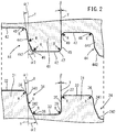
- the male thread stabbing flank 34 includes two male thread stabbing flank portions 341 and 342.
- the male thread stabbing flank portion 341 is farther from the pipe axis X of the steel pipe 20 and has a stabbing flank angle ⁇ 1.
- the male thread stabbing flank portion 342 is closer to the pipe axis X and has a stabbing flank angle ⁇ 2.
- the stabbing flank angles ⁇ 1 and ⁇ 2 are angles of inclination of the male thread stabbing flank 34 (male thread stabbing flank portions 341 and 342) relative to a plane Y perpendicular to the pipe axis X. If the stabbing flank 34 overhangs, the stabbing flank angle ⁇ 1 is negative.
- the stabbing flank angle ⁇ 2 is larger than the stabbing flank angle ⁇ 1 ( ⁇ 2> ⁇ 1).
- the stabbing flank angle ⁇ 1 is -15 to 15 degrees, and preferably 8 to 12 degrees, for example about 10 degrees.
- the stabbing flank angle ⁇ 2 is 20 to 60 degrees, and preferably 28 to 32 degrees, for example about 30 degrees.
- the male thread stabbing flank 34 is concave at about its middle.
- the height of the male thread stabbing flank portion 342 (i.e. length between the male thread root 33 and the border between the male thread stabbing flank portions 341 and 342) is 25 to 60 %, for example 35 %, of the height of the male thread.
- the female thread 41 includes a female thread crest 42, a female thread root 43, a female thread stabbing flank 44, and a female thread load flank 45.
- the female thread crest 42 faces the male thread root 33.
- the female thread root 43 faces the male thread crest 32.
- the female thread stabbing flank 44 faces the male thread stabbing flank 34.
- the female thread load flank 45 faces the male thread load flank 35.
- the female thread stabbing flank 44 includes two female thread stabbing flank portions 441 and 442.
- the female thread stabbing flank portion 441 is farther from the pipe axis X and has a stabbing flank angle ⁇ 1 equal to the stabbing flank angle ⁇ 1 of the male thread stabbing flank portion 341.
- the female thread stabbing flank portion 442 is located closer to the pipe axis X and has a stabbing flank angle ⁇ 2 equal to the stabbing flank angle ⁇ 2 of the male thread stabbing flank portion 342. As such, the female thread stabbing flank 44 is convex at about its middle.
- the stabbing flank angles ⁇ 1 and ⁇ 2 of the male thread stabbing flank portions 341 and 342 need not be exactly equal to the stabbing flank angles ⁇ 1 and ⁇ 2 of the female thread stabbing flank portions 441 and 442, and they are only required to be substantially equal. That is, the stabbing flank angles ⁇ 1 and ⁇ 2 may have errors of margin due to machining.
- the female thread stabbing flank portion 442 has a height equal to the height of the male thread stabbing flank portion 342. This prevents the clearance between the thread surfaces of the pin and box from becoming larger than necessary such that the thread seal construction will provide good sealing performance.
- the height of the male thread stabbing flank portion 342 need not be exactly equal to the height of the female thread stabbing flank portion 442, and they are only required to be substantially equal. That is, these heights may have errors of margin due to machining.
- the male thread 31 further includes male thread round surfaces 36 to 39.
- the male thread round surface 36 is located on the corner between the male thread crest 32 and male thread stabbing flank 34.
- the male thread round surface 37 is located on the corner between the male thread crest 32 and male thread load flank 35.
- the male thread round surface 38 is located on the corner between the male thread root 33 and male thread stabbing flank 34.
- the male thread round surface 39 is located on the corner between the male thread root 33 and male thread load flank 35.
- the female thread 41 includes a female thread round surfaces 46 to 49.
- the female thread round surface 46 is located on the corner between the female thread crest 42 and female thread stabbing flank 44.
- the female thread round surface 47 is located on the corner between the female thread crest 42 and female thread load surface 45.
- the female thread round surface 48 is located on the corner between the female thread root 43 and female thread stabbing flank 44.
- the female thread round surface 49 is located on the corner between the female thread root 43 and female thread load flank 45.
- the round surfaces 36 to 39 and 46 to 49 are so-called R surfaces (i.e. round chamfered surfaces) and have a predetermined radius of curvature.
- the radius of curvature is 0.1 to 1.2 mm, and preferably 0.3 to 0.8 mm.
- the male thread load flank 35 has a load flank angle ⁇ .
- the load flank angle ⁇ is an angle of inclination of the male thread load flank 35 relative to a plane Y perpendicular to the pipe axis X. If the load flank 35 overhangs, the load flank angle ⁇ is negative.
- the load flank angle ⁇ is -10 to 3 degrees, and preferably -5 to -1, and for example about -3 degrees.
- the female thread load flank 45 has a load flank angle ⁇ equal to the load flank angle ⁇ of the male thread load flank 35.
- the load flank angle ⁇ of the male thread load flank 35 need not be exactly equal to the load flank angle ⁇ of the female thread load flank 45, and they are only required to be substantially equal. That is, the load flank angle ⁇ may have an error of margin due to machining.
- the male thread crest 32, male thread root 33, female thread crest 42 and female thread root 43 are parallel to the pipe axis X. More specifically, the lines of the planes 32, 33, 42 and 43 appearing in a longitudinal cross section containing the pipe axis X are parallel to the pipe axis X.
- the male thread stabbing flank 34 and female thread stabbing flank 44 have a clearance therebetween of 60 to 120 ⁇ m when the connection has been made up.
- the male thread crest 32 and female thread root 43 have a clearance therebetween of 0 to 50 ⁇ m when the connection has been made up.
- the male thread root 33 and female thread crest 42 also have a clearance therebetween of 0 to 50 ⁇ m when the connection has been made up.
- the pin 30 further includes a pin shoulder surface 24 provided on the tip of the pin 30.
- the box 40 further includes a box shoulder surface 54 that is to be in contact with the pin shoulder surface 24 when the connection has been made up.
- the male thread 31 includes a tapered thread having a taper ratio decreasing as it goes away from the tip of the pin 30, as represented by TR1 to TR4.
- TR1 12.5 %
- TR2 12.0 %
- TR3 11.5 %
- TR4 11.0 %.
- the threaded connection 10 may include a metal seal.
- the pin 30 further includes a pin sealing surface 26 provided between the tip of the pin 30 and the male thread 31 and on the outer periphery of the pin 30.
- the box 50 further includes a box sealing surface 56 provided to face the pin sealing surface 26 and on the inner periphery of the box 50 to adhere to the pin sealing surface 26 when the connection has been made up.
- the pin sealing surface 26 and box sealing surfaces 56 form a metal seal.
- the box 50 may not include the protrusion 52.
- the pin shoulder surface 24 of the one pin 30 and the pin shoulder surface 24 of the other pin are in contact with each other when the connection has been made up.
- Embodiment 3 has a so-called pin-to-pin construction.
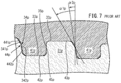
- the male thread 31p of the pin includes a male thread crest 32p, a male thread root 33p, a male thread stabbing flank 34p, and a male thread load flank 35p.
- the male thread stabbing flank 34p includes two male thread stabbing flank portions 341p and 342p.
- the stabbing flank angle ⁇ 2p of the stabbing flank portion 342p is smaller than the stabbing flank angle alp of the stabbing flank portion 341p ( ⁇ 2p ⁇ 1p).
- the male thread stabbing flank 34p is convex at about its middle.
- the female thread 41p of the box includes a female thread crest 42p, a female thread root 43p, a female thread stabbing flank 44p and a female thread load flank 45p.
- the female thread stabbing flank 44p includes two female thread stabbing flank portions 441p and 442p.
- the stabbing flank angle alp of the female thread stabbing flank portion 441p is equal to the stabbing flank angle alp of the male thread stabbing flank portion 341p.
- the stabbing flank angle ⁇ 2p of the female thread stabbing flank portion 442p is equal to the stabbing flank angle ⁇ 2p of the male thread stabbing flank portion 342p.
- the female thread stabbing flank 44p is concave at about its middle.
- stabbing position At the ideal stabbing position, at which the steel pipe 20 is aligned with the pipe axis of the coupling 50, the entire male thread crest is in contact with the entire female thread crest.
- the steel pipe 20, which is being hung swings due to effects of waves and winds, and thus a swing angle of about 1 degree is usually present.
- the lower limit of the pitch displacement angle at which cross-threading occurs depends on thread pitch and the outer diameter of the steel pipe. If the thread pitch is larger than 3 threads/inch, thread design is difficult. In a steel pipe with an outer diameter above 16 inches, the pitch displacement angle at which cross-threading occurs with 3 threads/inch is close to one degree. That is, a construction that prevents cross-threading, particularly in a large-diameter steel pipe with an outer diameter above 16 inches, is desired. Of course, a construction that prevents cross-threading in a steel pipe with an outer diameter of 16 inches or less is also suitable.
- An object of the present embodiment is to prevent cross-threading by having two-portion stabbing flanks without decreasing compression load resistance and galling resistance, i.e. to maintain them.
- each stabbing flank has two portions and the clearance between the threads is small, the sealing performance provided by the thread surfaces can be maintained.
- the stabbing flank angle of one of the two stabbing flank portions may be increased. Increasing the stabbing flank angle facilitates resolving a lock and prevents cross-threading.
- the embodiment shown in FIG. 12 has a small stabbing flank angle of the stabbing flank portion 441 closer to the box body, which has high stiffness, such that the stabbing flank portion 441 is susceptible to compression loads.
- the engagement of the threads can be maintained until the limit compression load is reached.
- a sealing performance can be maintained without a gap along a radial direction of the thread being present.
- the female thread restricts the male thread until the limit is reached at which jump-in occurs due to a limit compression load, thereby preventing the threads from being disengaged.
- the male thread of the pin provides perfect threads toward the front end and imperfect threads toward the rear end.
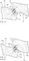
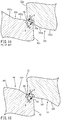
- a burr BR is created by the tool at an edge of an imperfect thread crest 32p or 32.
- This burr BR may lock a thread surface of the box, causing cross-threading.
- the surface facing the burr BR when the locks are resolved one after another to remove the relative inclination of the male thread relative to the female thread is flat and the stabbing flank angle is large.
- the burr BR on an imperfect thread does not slide in contact with the female thread round surface 46p located between the female thread crest 42p and stabbing flank 44p of the box. As such, in the implementation shown in FIG. 14 , a lock cannot easily be resolved and cross-threading tends to occur.
- a lock can be easily resolved and cross-threading is less likely to occur. Moreover, compression load resistance and galling resistance will not decrease, i.e. be maintained.
- Each of the threaded connections according to the Examples included two-portion stabbing flanks as described above.
- the stabbing flank angle ⁇ 1 was 10 degrees and the stabbing flank angle ⁇ 2 was 30 degrees.
- Both Comparative Examples 1 and 2 had usual one-portion stabbing flanks.
- the stabbing flank angle of Comparative Example 1 was 10 degree and the stabbing flank angle of Comparative Example 2 was 30 degrees.
- a make/break performance test a steel pipe was tightened until the amount of interference in radial directions of the threaded connection reached a predetermined level and then loosened (make/break test), and the make/break performance was evaluated based on whether galling occurred.
- a sealing performance test a threaded connection was filled with a liquid and was made up, and then a compression load substantially equal to the nominal yield strength of the steel pipe (100 %) was applied thereto, and the sealing performance was evaluated based on whether the liquid leaked.
- the stabbing performance test was conducted five times and cross-threading did not occur in any of the five rounds. Further, for each of the Examples, the make/break performance test was conducted three times and galling did not occur in any of the three rounds. In contrast, for Comparative Example 1, the stabbing performance test was conducted five times and cross-threading occurred in four of the five rounds. Although the make/break performance test was not conducted for Comparative Example 1, it is assumed that galling would not have occurred if stabbing had been successful without cross-threading. For Comparative Example 2, the stabbing performance test was conducted three times, and cross-threading did not occur in any of the three rounds. For Comparative Example 2, the make/break performance test was conducted three times and galling occurred in the third round.
- the male and female threads of the threaded connection according to Example 3 included two-portion stabbing flanks.
- the threaded connection according to Comparative Example 3 was the threaded connection according to prior art discussed above.
- the stabbing flank angle ⁇ 1 of Comparative Example 3 was 30 degrees and the stabbing flank angle ⁇ 2 was 10 degrees.
- FIGS. 16 and 17 Examples of calculation results from simulations of simple compression loads on the threaded connections according to the Examples and Comparative Example 3 are shown in FIGS. 16 and 17 .
- Each of these drawings shows that the pin 30 in each of the Examples and Comparative Example 3 was subjected to excessive compression loads and buckled. However, the amount of deformation due to buckling was smaller in the Examples shown in FIG. 16 than in Comparative Example 3 shown in FIG. 17 . This reveals that the Examples are less likely to buckle than Comparative Example 3, that is, have better compression load resistance.
- FIG. 18 shows an example of a contact stress distribution for one of the Examples.
- FIG. 17 shows an example of a contact stress distribution for Comparative Example 3.
- contact stresses on the stabbing flank during application of compression loads were higher at that one of the two stabbing flank portions which had a smaller stabbing flank angle. That is, it is estimated that, in the Example of FIG. 18 , a surface closer to the box body, which has a larger stiffness, supports the high contact stresses, thereby providing a better compression load resistance.
Landscapes
- Engineering & Computer Science (AREA)
- General Engineering & Computer Science (AREA)
- Mechanical Engineering (AREA)
- Mining & Mineral Resources (AREA)
- Life Sciences & Earth Sciences (AREA)
- Geology (AREA)
- Fluid Mechanics (AREA)
- Environmental & Geological Engineering (AREA)
- Physics & Mathematics (AREA)
- General Life Sciences & Earth Sciences (AREA)
- Geochemistry & Mineralogy (AREA)
- Non-Disconnectible Joints And Screw-Threaded Joints (AREA)
- Earth Drilling (AREA)
- Mutual Connection Of Rods And Tubes (AREA)
Applications Claiming Priority (2)
| Application Number | Priority Date | Filing Date | Title |
|---|---|---|---|
| JP2017070649 | 2017-03-31 | ||
| PCT/JP2018/008155 WO2018180218A1 (ja) | 2017-03-31 | 2018-03-02 | 鋼管用ねじ継手 |
Publications (3)
| Publication Number | Publication Date |
|---|---|
| EP3604881A1 true EP3604881A1 (de) | 2020-02-05 |
| EP3604881A4 EP3604881A4 (de) | 2020-04-15 |
| EP3604881B1 EP3604881B1 (de) | 2022-05-04 |
Family
ID=63677200
Family Applications (1)
| Application Number | Title | Priority Date | Filing Date |
|---|---|---|---|
| EP18774281.2A Active EP3604881B1 (de) | 2017-03-31 | 2018-03-02 | Schraubverbindung für stahlrohre |
Country Status (14)
| Country | Link |
|---|---|
| US (1) | US11067205B2 (de) |
| EP (1) | EP3604881B1 (de) |
| JP (1) | JP6795084B2 (de) |
| CN (1) | CN110476000B (de) |
| AR (1) | AR111444A1 (de) |
| AU (1) | AU2018246094B2 (de) |
| BR (1) | BR112019017165B1 (de) |
| CA (1) | CA3055505C (de) |
| EA (1) | EA038092B1 (de) |
| MX (1) | MX2019010415A (de) |
| MY (1) | MY201522A (de) |
| PL (1) | PL3604881T3 (de) |
| UA (1) | UA124780C2 (de) |
| WO (1) | WO2018180218A1 (de) |
Cited By (1)
| Publication number | Priority date | Publication date | Assignee | Title |
|---|---|---|---|---|
| CN111306376A (zh) * | 2020-03-06 | 2020-06-19 | 温州盛淼工业设计有限公司 | 一种管件连接器 |
Families Citing this family (12)
| Publication number | Priority date | Publication date | Assignee | Title |
|---|---|---|---|---|
| AU2018205080B2 (en) * | 2017-07-20 | 2024-08-08 | Illinois Tool Works Inc. | Coupler for threaded reinforcing bar |
| US11454268B2 (en) * | 2017-07-20 | 2022-09-27 | Illinois Tool Works Inc. | Coupler for threaded reinforcing bar |
| UA128488C2 (uk) | 2019-03-27 | 2024-07-24 | Ніппон Стіл Корпорейшн | Нарізне з'єднання для сталевої труби |
| WO2020247923A1 (en) * | 2019-06-06 | 2020-12-10 | Fermata Technologies, Llc | Arcuate thread form fit |
| JP6930683B1 (ja) * | 2020-01-06 | 2021-09-01 | 日本製鉄株式会社 | 鋼管ねじ継手構造 |
| AU2020423747B2 (en) * | 2020-01-17 | 2023-09-07 | Nippon Steel Corporation | Threaded connection for pipe |
| US11614186B1 (en) | 2020-03-25 | 2023-03-28 | PTC Liberty Tubulars LLC | Box connection for a pin with relieved thread region |
| CN112761539B (zh) * | 2021-01-05 | 2023-01-10 | 中国石油天然气集团有限公司 | 一种抗剪切气密封的螺纹接头 |
| AU2021221436A1 (en) | 2021-05-04 | 2022-11-24 | Illinois Tool Works Inc. | Coupler for threaded reinforcing bar |
| AU2021221844A1 (en) * | 2021-08-25 | 2023-03-16 | Illinois Tool Works Inc. | Connection system |
| EP4215716B1 (de) * | 2022-01-19 | 2024-07-31 | Tenaris Connections B.V. | Rohrschraubverbindung |
| WO2025234241A1 (ja) * | 2024-05-09 | 2025-11-13 | 日本製鉄株式会社 | ねじ継手及びねじ継手の製造方法 |
Family Cites Families (41)
| Publication number | Priority date | Publication date | Assignee | Title |
|---|---|---|---|---|
| JPS56143889A (en) * | 1980-04-12 | 1981-11-09 | Nippon Steel Corp | Screw joint for high airtightness oil pipe |
| US4549754A (en) * | 1983-06-20 | 1985-10-29 | Reed Tubular Products Company | Tool joint |
| JPS6026878A (ja) * | 1983-07-23 | 1985-02-09 | 新日本製鐵株式会社 | 油井用鋼管継手 |
| US4600224A (en) * | 1983-12-23 | 1986-07-15 | Interlock Technologies Corporation | Tubular connection having a chevron wedge thread |
| US4865364A (en) * | 1988-07-05 | 1989-09-12 | Vetco Gray Inc. | Conical thread form |
| JP2705505B2 (ja) * | 1993-03-24 | 1998-01-28 | 住友金属工業株式会社 | 油井管用ねじ継手 |
| FR2733570B1 (fr) * | 1995-04-28 | 1997-06-20 | Vallourec Oil & Gas | Assemblage filete pour tubes |
| US5931511A (en) * | 1997-05-02 | 1999-08-03 | Grant Prideco, Inc. | Threaded connection for enhanced fatigue resistance |
| WO1999008034A1 (en) * | 1997-08-11 | 1999-02-18 | Marubeni Tubulars, Inc. | Tubular connection |
| JPH11132370A (ja) * | 1997-10-29 | 1999-05-21 | Nippon Steel Corp | 鋼管用ねじ継手 |
| US6254146B1 (en) * | 1999-04-23 | 2001-07-03 | John Gandy Corporation | Thread form with multifacited flanks |
| US20020117856A1 (en) * | 1999-10-20 | 2002-08-29 | Beverly Watts Ramos | Wedgethread pipe connection |
| FR2800150B1 (fr) | 1999-10-21 | 2001-12-07 | Vallourec Mannesmann Oil & Gas | Joint tubulaire filette etanche a la pression exterieure |
| FR2807138B1 (fr) * | 2000-03-31 | 2002-05-17 | Vallourec Mannesmann Oil & Gas | Element filete tubulaire pour joint filete tubulaire resistant a la fatigue et joint filete tubulaire resultant |
| WO2001094831A1 (en) * | 2000-06-07 | 2001-12-13 | Sumitomo Metal Industries, Ltd. | Taper threaded joint |
| JP3744385B2 (ja) * | 2000-06-09 | 2006-02-08 | 住友金属工業株式会社 | 管継手 |
| FR2813375B1 (fr) * | 2000-08-31 | 2003-06-20 | Vallourec Mannesmann Oil & Gas | Element filete pour joint filete tubulaire resistant au grippage |
| FR2820806B1 (fr) * | 2001-02-09 | 2004-02-20 | Vallourec Mannesmann Oil & Gas | Joint filete tubulaire avec face de filet bombee convexe |
| JP2002349775A (ja) * | 2001-05-24 | 2002-12-04 | Sumitomo Metal Ind Ltd | テーパねじ継手 |
| ITRM20020234A1 (it) * | 2002-04-30 | 2003-10-30 | Tenaris Connections Bv | Giunzione filettata per tubi. |
| US6848724B2 (en) * | 2002-08-12 | 2005-02-01 | Grant Prideco, Inc. | Thread design for uniform distribution of makeup forces |
| WO2004070097A2 (en) * | 2003-01-29 | 2004-08-19 | Grant Prideco, L.P. | Fast make-up fatigue resistant rotary shouldered connection |
| FR2863681B1 (fr) * | 2003-12-11 | 2006-02-24 | Vallourec Mannesmann Oil & Gas | Joint tubulaire a filetages coniques resistant a la fatigue |
| EP2002165B1 (de) * | 2006-03-31 | 2017-09-06 | Nippon Steel & Sumitomo Metal Corporation | Rohrförmige gewindeverbindung |
| JP4941058B2 (ja) * | 2007-04-02 | 2012-05-30 | 住友金属工業株式会社 | 鋼管用ねじ継手 |
| CN201184462Y (zh) * | 2008-04-22 | 2009-01-21 | 西南石油大学 | 高膨胀率补贴管接头螺纹 |
| US8267436B2 (en) * | 2009-07-08 | 2012-09-18 | Gandy Technologies Corporation | Arrow-shaped thread form for tubular connections |
| US8535762B2 (en) | 2009-10-09 | 2013-09-17 | Tenaris Connections Limited | Tubular joint having wedge threads with surface coating |
| US20110101684A1 (en) * | 2009-11-04 | 2011-05-05 | Gandy Technologies Corporation | Threaded Pipe Connection with a Pressure Energized Flex Seal |
| FR2953272B1 (fr) * | 2009-11-30 | 2011-12-16 | Vallourec Mannesmann Oil & Gas | Joint filete |
| EP2420646A1 (de) * | 2010-08-16 | 2012-02-22 | TPS-Technitube Röhrenwerke GmbH | Rohrverbindung |
| CN202055773U (zh) * | 2011-05-23 | 2011-11-30 | 无锡西姆莱斯石油专用管制造有限公司 | 防粘扣螺纹接头 |
| US20120298249A1 (en) * | 2011-05-24 | 2012-11-29 | Banker Edward O | Tubular connection and associated thread form |
| US9869414B2 (en) * | 2011-05-24 | 2018-01-16 | Ultra Premium Oilfield Services, Ltd. | Tubular connection and associated threadform |
| US8668232B2 (en) * | 2011-12-09 | 2014-03-11 | Tenaris Connections Limited | Threaded connection with improved root thread profile |
| EP2899440B1 (de) * | 2012-09-21 | 2021-07-21 | Nippon Steel Corporation | Schraubverbindung für stahlrohre |
| MX2016007276A (es) * | 2013-12-05 | 2016-08-11 | Nippon Steel & Sumitomo Metal Corp | Union roscada para tuberias de acero. |
| FR3014534B1 (fr) * | 2013-12-10 | 2015-12-04 | Vallourec Oil & Gas France | Ensemble pour la realisation d'un joint filete pour le forage et l'exploitation des puits d'hydrocarbures et joint filete resultant |
| AR100804A1 (es) * | 2014-06-23 | 2016-11-02 | Nippon Steel & Sumitomo Metal Corp | Conexión roscada para tuberías de la industria del petróleo y composición para recubrimiento fotocurable |
| US9874058B2 (en) * | 2014-07-31 | 2018-01-23 | Baker Hughes, A Ge Company, Llc | Fatigue resistant thread profile with combined curve rounding |
| CN107110407B (zh) | 2014-10-06 | 2020-04-17 | 日本制铁株式会社 | 钢管用螺纹接头 |
-
2018
- 2018-03-02 BR BR112019017165-7A patent/BR112019017165B1/pt active IP Right Grant
- 2018-03-02 PL PL18774281.2T patent/PL3604881T3/pl unknown
- 2018-03-02 CN CN201880022821.1A patent/CN110476000B/zh active Active
- 2018-03-02 MX MX2019010415A patent/MX2019010415A/es unknown
- 2018-03-02 EP EP18774281.2A patent/EP3604881B1/de active Active
- 2018-03-02 MY MYPI2019005065A patent/MY201522A/en unknown
- 2018-03-02 EA EA201992035A patent/EA038092B1/ru unknown
- 2018-03-02 JP JP2019509070A patent/JP6795084B2/ja active Active
- 2018-03-02 US US16/495,420 patent/US11067205B2/en active Active
- 2018-03-02 CA CA3055505A patent/CA3055505C/en active Active
- 2018-03-02 WO PCT/JP2018/008155 patent/WO2018180218A1/ja not_active Ceased
- 2018-03-02 UA UAA201910009A patent/UA124780C2/uk unknown
- 2018-03-02 AU AU2018246094A patent/AU2018246094B2/en active Active
- 2018-03-27 AR ARP180100725A patent/AR111444A1/es active IP Right Grant
Cited By (2)
| Publication number | Priority date | Publication date | Assignee | Title |
|---|---|---|---|---|
| CN111306376A (zh) * | 2020-03-06 | 2020-06-19 | 温州盛淼工业设计有限公司 | 一种管件连接器 |
| CN111306376B (zh) * | 2020-03-06 | 2021-03-26 | 温州盛淼工业设计有限公司 | 一种管件连接器 |
Also Published As
| Publication number | Publication date |
|---|---|
| CN110476000B (zh) | 2021-08-24 |
| EA201992035A1 (ru) | 2020-02-28 |
| MY201522A (en) | 2024-02-27 |
| CN110476000A (zh) | 2019-11-19 |
| BR112019017165B1 (pt) | 2023-01-24 |
| AR111444A1 (es) | 2019-07-17 |
| JP6795084B2 (ja) | 2020-12-02 |
| UA124780C2 (uk) | 2021-11-17 |
| CA3055505C (en) | 2021-12-14 |
| AU2018246094B2 (en) | 2021-02-04 |
| EA038092B1 (ru) | 2021-07-05 |
| EP3604881A4 (de) | 2020-04-15 |
| MX2019010415A (es) | 2019-10-15 |
| AU2018246094A1 (en) | 2019-09-12 |
| EP3604881B1 (de) | 2022-05-04 |
| BR112019017165A2 (pt) | 2020-04-14 |
| PL3604881T3 (pl) | 2022-08-22 |
| WO2018180218A1 (ja) | 2018-10-04 |
| JPWO2018180218A1 (ja) | 2019-06-27 |
| CA3055505A1 (en) | 2018-10-04 |
| US20200025315A1 (en) | 2020-01-23 |
| US11067205B2 (en) | 2021-07-20 |
Similar Documents
| Publication | Publication Date | Title |
|---|---|---|
| EP3604881B1 (de) | Schraubverbindung für stahlrohre | |
| CN101438089B (zh) | 管螺纹接头 | |
| EP3366968B1 (de) | Gewindeanschluss für stahlrohre | |
| EP3702656B1 (de) | Schraubverbindung für stahlrohr | |
| EP4036449B1 (de) | Schraubverbindung | |
| US11391399B2 (en) | Threaded connection for steel pipes | |
| AU2023200342B2 (en) | Threaded connection for steel pipe | |
| JPWO2020183860A1 (ja) | ねじ継手 | |
| OA19802A (en) | Threaded joint for steel pipe. | |
| OA21091A (en) | Screw-threaded joint | |
| OA20843A (en) | Threaded Coupling For Steel Pipe |
Legal Events
| Date | Code | Title | Description |
|---|---|---|---|
| STAA | Information on the status of an ep patent application or granted ep patent |
Free format text: STATUS: THE INTERNATIONAL PUBLICATION HAS BEEN MADE |
|
| PUAI | Public reference made under article 153(3) epc to a published international application that has entered the european phase |
Free format text: ORIGINAL CODE: 0009012 |
|
| STAA | Information on the status of an ep patent application or granted ep patent |
Free format text: STATUS: REQUEST FOR EXAMINATION WAS MADE |
|
| 17P | Request for examination filed |
Effective date: 20190829 |
|
| AK | Designated contracting states |
Kind code of ref document: A1 Designated state(s): AL AT BE BG CH CY CZ DE DK EE ES FI FR GB GR HR HU IE IS IT LI LT LU LV MC MK MT NL NO PL PT RO RS SE SI SK SM TR |
|
| AX | Request for extension of the european patent |
Extension state: BA ME |
|
| A4 | Supplementary search report drawn up and despatched |
Effective date: 20200313 |
|
| RIC1 | Information provided on ipc code assigned before grant |
Ipc: F16L 15/06 20060101ALI20200309BHEP Ipc: E21B 17/042 20060101ALI20200309BHEP Ipc: F16L 15/04 20060101AFI20200309BHEP Ipc: F16L 15/00 20060101ALI20200309BHEP |
|
| DAV | Request for validation of the european patent (deleted) | ||
| DAX | Request for extension of the european patent (deleted) | ||
| GRAP | Despatch of communication of intention to grant a patent |
Free format text: ORIGINAL CODE: EPIDOSNIGR1 |
|
| STAA | Information on the status of an ep patent application or granted ep patent |
Free format text: STATUS: GRANT OF PATENT IS INTENDED |
|
| INTG | Intention to grant announced |
Effective date: 20211216 |
|
| GRAS | Grant fee paid |
Free format text: ORIGINAL CODE: EPIDOSNIGR3 |
|
| GRAA | (expected) grant |
Free format text: ORIGINAL CODE: 0009210 |
|
| STAA | Information on the status of an ep patent application or granted ep patent |
Free format text: STATUS: THE PATENT HAS BEEN GRANTED |
|
| AK | Designated contracting states |
Kind code of ref document: B1 Designated state(s): AL AT BE BG CH CY CZ DE DK EE ES FI FR GB GR HR HU IE IS IT LI LT LU LV MC MK MT NL NO PL PT RO RS SE SI SK SM TR |
|
| REG | Reference to a national code |
Ref country code: GB Ref legal event code: FG4D |
|
| REG | Reference to a national code |
Ref country code: RO Ref legal event code: EPE |
|
| REG | Reference to a national code |
Ref country code: CH Ref legal event code: EP |
|
| REG | Reference to a national code |
Ref country code: AT Ref legal event code: REF Ref document number: 1489383 Country of ref document: AT Kind code of ref document: T Effective date: 20220515 |
|
| REG | Reference to a national code |
Ref country code: IE Ref legal event code: FG4D Ref country code: DE Ref legal event code: R096 Ref document number: 602018035024 Country of ref document: DE |
|
| REG | Reference to a national code |
Ref country code: NL Ref legal event code: FP |
|
| REG | Reference to a national code |
Ref country code: NO Ref legal event code: T2 Effective date: 20220504 |
|
| REG | Reference to a national code |
Ref country code: LT Ref legal event code: MG9D |
|
| PG25 | Lapsed in a contracting state [announced via postgrant information from national office to epo] |
Ref country code: SE Free format text: LAPSE BECAUSE OF FAILURE TO SUBMIT A TRANSLATION OF THE DESCRIPTION OR TO PAY THE FEE WITHIN THE PRESCRIBED TIME-LIMIT Effective date: 20220504 Ref country code: PT Free format text: LAPSE BECAUSE OF FAILURE TO SUBMIT A TRANSLATION OF THE DESCRIPTION OR TO PAY THE FEE WITHIN THE PRESCRIBED TIME-LIMIT Effective date: 20220905 Ref country code: LT Free format text: LAPSE BECAUSE OF FAILURE TO SUBMIT A TRANSLATION OF THE DESCRIPTION OR TO PAY THE FEE WITHIN THE PRESCRIBED TIME-LIMIT Effective date: 20220504 Ref country code: HR Free format text: LAPSE BECAUSE OF FAILURE TO SUBMIT A TRANSLATION OF THE DESCRIPTION OR TO PAY THE FEE WITHIN THE PRESCRIBED TIME-LIMIT Effective date: 20220504 Ref country code: GR Free format text: LAPSE BECAUSE OF FAILURE TO SUBMIT A TRANSLATION OF THE DESCRIPTION OR TO PAY THE FEE WITHIN THE PRESCRIBED TIME-LIMIT Effective date: 20220805 Ref country code: FI Free format text: LAPSE BECAUSE OF FAILURE TO SUBMIT A TRANSLATION OF THE DESCRIPTION OR TO PAY THE FEE WITHIN THE PRESCRIBED TIME-LIMIT Effective date: 20220504 Ref country code: ES Free format text: LAPSE BECAUSE OF FAILURE TO SUBMIT A TRANSLATION OF THE DESCRIPTION OR TO PAY THE FEE WITHIN THE PRESCRIBED TIME-LIMIT Effective date: 20220504 Ref country code: BG Free format text: LAPSE BECAUSE OF FAILURE TO SUBMIT A TRANSLATION OF THE DESCRIPTION OR TO PAY THE FEE WITHIN THE PRESCRIBED TIME-LIMIT Effective date: 20220804 |
|
| PG25 | Lapsed in a contracting state [announced via postgrant information from national office to epo] |
Ref country code: RS Free format text: LAPSE BECAUSE OF FAILURE TO SUBMIT A TRANSLATION OF THE DESCRIPTION OR TO PAY THE FEE WITHIN THE PRESCRIBED TIME-LIMIT Effective date: 20220504 Ref country code: LV Free format text: LAPSE BECAUSE OF FAILURE TO SUBMIT A TRANSLATION OF THE DESCRIPTION OR TO PAY THE FEE WITHIN THE PRESCRIBED TIME-LIMIT Effective date: 20220504 Ref country code: IS Free format text: LAPSE BECAUSE OF FAILURE TO SUBMIT A TRANSLATION OF THE DESCRIPTION OR TO PAY THE FEE WITHIN THE PRESCRIBED TIME-LIMIT Effective date: 20220904 |
|
| PG25 | Lapsed in a contracting state [announced via postgrant information from national office to epo] |
Ref country code: SM Free format text: LAPSE BECAUSE OF FAILURE TO SUBMIT A TRANSLATION OF THE DESCRIPTION OR TO PAY THE FEE WITHIN THE PRESCRIBED TIME-LIMIT Effective date: 20220504 Ref country code: SK Free format text: LAPSE BECAUSE OF FAILURE TO SUBMIT A TRANSLATION OF THE DESCRIPTION OR TO PAY THE FEE WITHIN THE PRESCRIBED TIME-LIMIT Effective date: 20220504 Ref country code: EE Free format text: LAPSE BECAUSE OF FAILURE TO SUBMIT A TRANSLATION OF THE DESCRIPTION OR TO PAY THE FEE WITHIN THE PRESCRIBED TIME-LIMIT Effective date: 20220504 Ref country code: DK Free format text: LAPSE BECAUSE OF FAILURE TO SUBMIT A TRANSLATION OF THE DESCRIPTION OR TO PAY THE FEE WITHIN THE PRESCRIBED TIME-LIMIT Effective date: 20220504 |
|
| REG | Reference to a national code |
Ref country code: DE Ref legal event code: R097 Ref document number: 602018035024 Country of ref document: DE |
|
| PLBE | No opposition filed within time limit |
Free format text: ORIGINAL CODE: 0009261 |
|
| STAA | Information on the status of an ep patent application or granted ep patent |
Free format text: STATUS: NO OPPOSITION FILED WITHIN TIME LIMIT |
|
| PG25 | Lapsed in a contracting state [announced via postgrant information from national office to epo] |
Ref country code: AL Free format text: LAPSE BECAUSE OF FAILURE TO SUBMIT A TRANSLATION OF THE DESCRIPTION OR TO PAY THE FEE WITHIN THE PRESCRIBED TIME-LIMIT Effective date: 20220504 |
|
| 26N | No opposition filed |
Effective date: 20230207 |
|
| PG25 | Lapsed in a contracting state [announced via postgrant information from national office to epo] |
Ref country code: SI Free format text: LAPSE BECAUSE OF FAILURE TO SUBMIT A TRANSLATION OF THE DESCRIPTION OR TO PAY THE FEE WITHIN THE PRESCRIBED TIME-LIMIT Effective date: 20220504 |
|
| REG | Reference to a national code |
Ref country code: AT Ref legal event code: UEP Ref document number: 1489383 Country of ref document: AT Kind code of ref document: T Effective date: 20220504 |
|
| PG25 | Lapsed in a contracting state [announced via postgrant information from national office to epo] |
Ref country code: MC Free format text: LAPSE BECAUSE OF FAILURE TO SUBMIT A TRANSLATION OF THE DESCRIPTION OR TO PAY THE FEE WITHIN THE PRESCRIBED TIME-LIMIT Effective date: 20220504 |
|
| REG | Reference to a national code |
Ref country code: CH Ref legal event code: PL |
|
| REG | Reference to a national code |
Ref country code: BE Ref legal event code: MM Effective date: 20230331 |
|
| PG25 | Lapsed in a contracting state [announced via postgrant information from national office to epo] |
Ref country code: LU Free format text: LAPSE BECAUSE OF NON-PAYMENT OF DUE FEES Effective date: 20230302 |
|
| REG | Reference to a national code |
Ref country code: IE Ref legal event code: MM4A |
|
| PG25 | Lapsed in a contracting state [announced via postgrant information from national office to epo] |
Ref country code: LI Free format text: LAPSE BECAUSE OF NON-PAYMENT OF DUE FEES Effective date: 20230331 Ref country code: IE Free format text: LAPSE BECAUSE OF NON-PAYMENT OF DUE FEES Effective date: 20230302 Ref country code: CH Free format text: LAPSE BECAUSE OF NON-PAYMENT OF DUE FEES Effective date: 20230331 |
|
| PG25 | Lapsed in a contracting state [announced via postgrant information from national office to epo] |
Ref country code: BE Free format text: LAPSE BECAUSE OF NON-PAYMENT OF DUE FEES Effective date: 20230331 |
|
| PG25 | Lapsed in a contracting state [announced via postgrant information from national office to epo] |
Ref country code: BG Free format text: LAPSE BECAUSE OF FAILURE TO SUBMIT A TRANSLATION OF THE DESCRIPTION OR TO PAY THE FEE WITHIN THE PRESCRIBED TIME-LIMIT Effective date: 20220504 |
|
| PG25 | Lapsed in a contracting state [announced via postgrant information from national office to epo] |
Ref country code: BG Free format text: LAPSE BECAUSE OF FAILURE TO SUBMIT A TRANSLATION OF THE DESCRIPTION OR TO PAY THE FEE WITHIN THE PRESCRIBED TIME-LIMIT Effective date: 20220504 |
|
| PGFP | Annual fee paid to national office [announced via postgrant information from national office to epo] |
Ref country code: PL Payment date: 20250214 Year of fee payment: 8 Ref country code: CZ Payment date: 20250218 Year of fee payment: 8 |
|
| PG25 | Lapsed in a contracting state [announced via postgrant information from national office to epo] |
Ref country code: CY Free format text: LAPSE BECAUSE OF FAILURE TO SUBMIT A TRANSLATION OF THE DESCRIPTION OR TO PAY THE FEE WITHIN THE PRESCRIBED TIME-LIMIT; INVALID AB INITIO Effective date: 20180302 |
|
| PG25 | Lapsed in a contracting state [announced via postgrant information from national office to epo] |
Ref country code: HU Free format text: LAPSE BECAUSE OF FAILURE TO SUBMIT A TRANSLATION OF THE DESCRIPTION OR TO PAY THE FEE WITHIN THE PRESCRIBED TIME-LIMIT; INVALID AB INITIO Effective date: 20180302 |
|
| PG25 | Lapsed in a contracting state [announced via postgrant information from national office to epo] |
Ref country code: TR Free format text: LAPSE BECAUSE OF FAILURE TO SUBMIT A TRANSLATION OF THE DESCRIPTION OR TO PAY THE FEE WITHIN THE PRESCRIBED TIME-LIMIT Effective date: 20220504 |
|
| PGFP | Annual fee paid to national office [announced via postgrant information from national office to epo] |
Ref country code: NL Payment date: 20260213 Year of fee payment: 9 |
|
| PGFP | Annual fee paid to national office [announced via postgrant information from national office to epo] |
Ref country code: GB Payment date: 20260202 Year of fee payment: 9 |
|
| PGFP | Annual fee paid to national office [announced via postgrant information from national office to epo] |
Ref country code: NO Payment date: 20260310 Year of fee payment: 9 Ref country code: DE Payment date: 20260128 Year of fee payment: 9 |
|
| PGFP | Annual fee paid to national office [announced via postgrant information from national office to epo] |
Ref country code: AT Payment date: 20260225 Year of fee payment: 9 |
|
| PGFP | Annual fee paid to national office [announced via postgrant information from national office to epo] |
Ref country code: RO Payment date: 20260226 Year of fee payment: 9 Ref country code: IT Payment date: 20260220 Year of fee payment: 9 |
|
| PGFP | Annual fee paid to national office [announced via postgrant information from national office to epo] |
Ref country code: FR Payment date: 20260209 Year of fee payment: 9 |