EP3605574A1 - Bauraumoptimierte abtrennvorrichtung - Google Patents
Bauraumoptimierte abtrennvorrichtung Download PDFInfo
- Publication number
- EP3605574A1 EP3605574A1 EP19188998.9A EP19188998A EP3605574A1 EP 3605574 A1 EP3605574 A1 EP 3605574A1 EP 19188998 A EP19188998 A EP 19188998A EP 3605574 A1 EP3605574 A1 EP 3605574A1
- Authority
- EP
- European Patent Office
- Prior art keywords
- electrical component
- display means
- carrier
- mechanically displaceable
- displaceable display
- Prior art date
- Legal status (The legal status is an assumption and is not a legal conclusion. Google has not performed a legal analysis and makes no representation as to the accuracy of the status listed.)
- Granted
Links
Images

Classifications
-
- H—ELECTRICITY
- H01—ELECTRIC ELEMENTS
- H01H—ELECTRIC SWITCHES; RELAYS; SELECTORS; EMERGENCY PROTECTIVE DEVICES
- H01H9/00—Details of switching devices, not covered by groups H01H1/00 - H01H7/00
- H01H9/18—Distinguishing marks on switches, e.g. for indicating switch location in the dark; Adaptation of switches to receive distinguishing marks
-
- H—ELECTRICITY
- H01—ELECTRIC ELEMENTS
- H01H—ELECTRIC SWITCHES; RELAYS; SELECTORS; EMERGENCY PROTECTIVE DEVICES
- H01H37/00—Thermally-actuated switches
- H01H37/74—Switches in which only the opening movement or only the closing movement of a contact is effected by heating or cooling
- H01H37/76—Contact member actuated by melting of fusible material, actuated due to burning of combustible material or due to explosion of explosive material
- H01H37/761—Contact member actuated by melting of fusible material, actuated due to burning of combustible material or due to explosion of explosive material with a fusible element forming part of the switched circuit
-
- H—ELECTRICITY
- H01—ELECTRIC ELEMENTS
- H01H—ELECTRIC SWITCHES; RELAYS; SELECTORS; EMERGENCY PROTECTIVE DEVICES
- H01H37/00—Thermally-actuated switches
- H01H37/74—Switches in which only the opening movement or only the closing movement of a contact is effected by heating or cooling
- H01H37/76—Contact member actuated by melting of fusible material, actuated due to burning of combustible material or due to explosion of explosive material
- H01H37/761—Contact member actuated by melting of fusible material, actuated due to burning of combustible material or due to explosion of explosive material with a fusible element forming part of the switched circuit
- H01H2037/762—Contact member actuated by melting of fusible material, actuated due to burning of combustible material or due to explosion of explosive material with a fusible element forming part of the switched circuit using a spring for opening the circuit when the fusible element melts
-
- H—ELECTRICITY
- H01—ELECTRIC ELEMENTS
- H01H—ELECTRIC SWITCHES; RELAYS; SELECTORS; EMERGENCY PROTECTIVE DEVICES
- H01H37/00—Thermally-actuated switches
- H01H37/74—Switches in which only the opening movement or only the closing movement of a contact is effected by heating or cooling
- H01H37/76—Contact member actuated by melting of fusible material, actuated due to burning of combustible material or due to explosion of explosive material
- H01H37/761—Contact member actuated by melting of fusible material, actuated due to burning of combustible material or due to explosion of explosive material with a fusible element forming part of the switched circuit
- H01H2037/762—Contact member actuated by melting of fusible material, actuated due to burning of combustible material or due to explosion of explosive material with a fusible element forming part of the switched circuit using a spring for opening the circuit when the fusible element melts
- H01H2037/763—Contact member actuated by melting of fusible material, actuated due to burning of combustible material or due to explosion of explosive material with a fusible element forming part of the switched circuit using a spring for opening the circuit when the fusible element melts the spring being a blade spring
Definitions
- the invention relates to a space-optimized separation device.
- This operation outside the nominal operating range can lead to an increased power conversion in the electrical component, which in turn leads to heating of the electrical component.
- Values can be achieved that lie outside the respective specification and can lead to self-damage to the electrical component as well as to neighboring systems.
- the heat generated in the vicinity of the electrical component can cause damage to components or a shift in characteristic curves, destruction of components or even a fire or explosion.
- the electrical component itself can also be led through the heating into a self-destructive operation, which can lead to destruction of the electrical component with a possible further impairment of neighboring systems, as stated above.
- the inadmissible heating of the electrical component is not prevented, it can lead to damage to surrounding materials, the generation of smoke gases or a fire hazard.
- thermosensitive connection is generally made using a solder connection.
- the contact element is mounted pretensioned or a force of a second pretensioned element, for example a spring, acts on the contact element. If the spring force exceeds the holding force of the thermosensitive contact point, eg the soldering point, the contact opens and the monitored component is switched off.
- Analog fuses are also used in other areas. From the DE 10 2008 057 166 A1 an electrical circuit with temperature protection is known in which a surface-mounted component is displaced by a spring element. From the DE 10 2005 040 308 A1 a thermal fuse is known in which a contact bridge can be moved. From the DE 10 2009 036 578 B3 a thermal fuse is known, in which contact bridges are also moved.
- references to standards or specifications or norms are to be understood as references to standards or specifications or norms that apply / apply at the time of registration and / or - if priority is claimed - at the time of priority registration. However, this is not to be understood as a general exclusion of the applicability to subsequent or replacing standards or specifications or norms.
- Neighboring explicitly includes a direct neighborhood relationship below, but is not limited to this. In the following one explicitly includes Location in which the intermediate part has a direct neighborhood to the surrounding parts.
- FIG. 1-4 is a first embodiment and in Figures 5-8 a second embodiment of a space-saving separation device 1 according to the invention is shown.
- a space-saving separation device 1 It is common to all embodiments of a space-saving separation device 1 according to the invention that it has a carrier P with an electrical component B.
- the electrical component B can in particular have an overvoltage protection element.
- the carrier P can e.g. be a circuit board or have a circuit board material. As a rule, the carrier will be essentially rigid.
- the purpose of the space-saving separation device 1 according to the invention is to separate the electrical component B in the event of inadmissible heating.
- the carrier P has at least two guide grooves N1, N2. These guide grooves N1, N2 can e.g. be introduced into the carrier P by means of punching, laser processing, milling, etc.
- the electrical component B is fastened on the carrier P with a thermally softenable fixation.
- the thermally softenable fixation can have a solder and / or an adhesive. If the heat-softenable fixation has a solder, then, for example, the electrical component B can have connections for surface mounting for conductor tracks of the carrier P.
- the electrical component B and with it also the solder heat to temperatures that are above the softening point of the solder but below the softening point of the adhesive. In this case, the solder still establishes the electrical connection because it remains in contact due to the surface forces.
- an energy accumulator D is arranged relative to the electrical component B, which - when the thermally softenable fixation softens - shifts the electrical component B essentially parallel to the carrier P and thereby separates the electrical component B.
- the energy store D can e.g. a spring (as shown) or a spring clip, a compressed elastomer, etc.
- the energy accumulator D exerts a continuous force after assembly, which in the event that the fixation softens leads to a movement.
- a displacement by pressure is shown in the figures, the invention is not limited to this.
- All embodiments of an installation space-optimized separation device 1 according to the invention also have in common that they have a mechanically displaceable display means S, the mechanically displaceable display means S indicating that the electrical component B to be monitored has been disconnected, the mechanically displaceable display means S together with the separating electrical component is moved.
- the mechanically displaceable display means S enclose the electrical component B laterally, ie in a plane parallel to the carrier P, or, as in Figures 7 and 8 shown, partially bordering.
- the Energy store D can be moved indirectly via the mechanically movable display means S, moves in Figures 7 and 8 the energy store D via the electrical component B the mechanically displaceable display means S.
- the mechanically displaceable display means S covers the electrical component in a hood-like manner.
- the mechanically displaceable display means S has further properties, such as, for example, extinguishing properties, for example in that it has hard gas material. Furthermore, it can also be provided that the design of the mechanical display means S, when triggered, constricts and / or extends a possible arc path. In addition, it can be provided that the mechanical display means S also functions as a heat sink for the electrical component B.
- the mechanically displaceable display means S is held and guided in the at least two guide grooves N1, N2.
- the arrangement of the first embodiment differs from the second embodiment in that the holder is achieved in that the in the embodiment of Figure 4 an inward wrap is displayed while in Figure 6 an outward wrap is indicated. It should be noted that a wrap around in the same direction is also possible.
- Such encirclements can be provided as molded parts which are guided through the guide grooves N1, N2 in a resilient and / or pressing manner during the assembly of the mechanically displaceable display means S and which expand again after the implementation. That the mechanically displaceable display means S can e.g. be snapped on. However, it is also possible to form encapsulations on the mechanically displaceable display means S by inserting them into the guide grooves N1, N2.
- a disconnecting device 1 can now be mounted on the carrier P after the electrical component B has been installed, without the risk that Elements can slip.
- the energy store D can be used.
- the electrical component B heats up, the electrical component B is released after the energy storage device D has been released, e.g. in the event of an error, moved along the surface of the carrier P.
- the travel path of the electrical component B can be used to simultaneously implement a mechanical display.
- the invention makes it possible to produce a simple and safe and inexpensive separation device which takes up little installation space and can also signal a separation.
- the mechanically displaceable display means S it is also possible for the mechanically displaceable display means S to have a device for fixing the mechanically displaceable display means S in an initial position.
- This fixation is preferably provided by the previously fixed electrical component B. That the manufacturing process can be further simplified and the security against tripping increased.
- the disconnection device 1 for a disconnected electrical component B it is also possible for the disconnection device 1 for a disconnected electrical component B to be monitored to have a device for fixing in a disconnected state.
- a hood-like mechanically displaceable display means S and the carrier P can fix the separated electrical component B.
- the arrangement described above makes it possible To implement devices with electrical components B and a separation device according to the invention, which do not have a supporting housing wall due to the design. If the mechanically displaceable display means S encompasses the separated electrical component B only laterally, a housing section parallel to the carrier P can prevent the electrical component B from becoming vaguely normal to the carrier P.
- the mechanically displaceable display means S can provide a color change and / or a change in transmission.
- an opening ANZ can be provided in a housing and / or in the carrier P, in which an color change field is shifted with / on the mechanically displaceable display means S when the electrical component B is separated. That e.g. a color change from green to red indicates that the separation has taken place.
- an embodiment is shown in which an opening ANZ in the carrier P is covered by the mechanical display means S ( Fig. 2 ) can be.
- an embodiment is shown in which an opening ANZ in the carrier P is opened by the mechanical display means S ( Fig. 8 ) can be.
- the separating device 1 it is also possible for the separating device 1 to have devices for mounting on a mounting rail.
- a separating device 1 according to the invention can also be installed in switch cabinets by means of suitable housings with the corresponding devices.
- guide grooves N1, N2 are shown in the figures, the invention is not limited to this. Rather, there are no limits for the person skilled in the art. However, essentially straight guide grooves N1, N2 allow particularly simple movement.
Landscapes
- Chemical & Material Sciences (AREA)
- Engineering & Computer Science (AREA)
- Combustion & Propulsion (AREA)
- Fuses (AREA)
- Cooling Or The Like Of Electrical Apparatus (AREA)
Abstract
Description
- Die Erfindung betrifft eine bauraumoptimierte Abtrennvorrichtung.
- Es ist bekannt, dass die Überbeanspruchung von elektrischen Bauelementen dazu führen kann, dass die elektrischen Bauelemente außerhalb ihres spezifizierten Nennbetriebsbereiches arbeiten. Auch andere Effekte, die von außen (unbeabsichtigt) eingeprägt sein können, können zu einem Betrieb außerhalb des Nennbetriebsbereiches führen.
- Dieser Betrieb außerhalb des Nennbetriebsbereiches kann zu einem erhöhten Leistungsumsatz in dem elektrischen Bauelement führen, welcher wiederum zu einer Erwärmung des elektrischen Bauelementes führt. Dabei können Werte erreicht werden, die außerhalb der jeweiligen Spezifikation liegen und zu einer Eigenschädigung des elektrischen Bauelementes als auch benachbarter Anlagen führen kann. Beispielsweise kann durch die entstandene Wärme in der Nachbarschaft des elektrischen Bauelements eine Schädigung von Bauteilen oder eine Verschiebung von Kennlinien, eine Zerstörung von Bauteilen bis hin zu Brand oder Explosion verursacht werden. Ebenso kann aber auch das elektrische Bauelement selbst durch die Erwärmung in einen selbstzerstörerischen Betrieb geführt werden, der zu einer Zerstörung des elektrischen Bauelements mit einer eventuellen weiteren Beeinträchtigung benachbarter Analgen wie zuvor ausgeführt führen kann.
- Beispielsweise kann eine reduzierte Bauteilisolationsfestigkeit, z.B. bei Schädigung, eines Ableiters, zu einem erhöhten Leistungsumsatz am geschädigten elektrischen Bauteil führen, die wiederum zu einer unzulässigen Erwärmung des elektrischen Bauelements führt.
- Wird die unzulässige Erwärmung des elektrischen Bauelements nicht verhindert, kann es z.B. zur Schädigung umgebender Materialien, Entstehung von Rauchgasen oder zu einer Brandgefahr führen.
- Daher wurde in der Vergangenheit, z.B. in
DE 90 102 46 U1 , vorgeschlagene eine Temperatursicherung einem Bauelement zuzuordnen, um eine Abschaltung bei Erwärmung zu ermöglichen. Aufgrund der begrenzten thermischen Ankopplungsmöglichkeit ist diese Anordnung für sehr schnelle Erwärmungsvorgänge jedoch nicht geeignet. - Bei Überspannungsschutzgeräten ist es üblich, die verwendeten Überspannungsschutzbauelemente, insbesondere Varistoren, mit thermisch aktivierten Abschalteinrichtungen auszustatten. In den Patenten
DE 42 41 311 C2 ,DE 699 04 274 T2 undUS 6,430,019 werden thermische Abtrennvorrichtungen für geschädigte Überspannungsschutzbauelemente beschrieben. Die in den Schriften beschriebenen Lösungen arbeiten alle nach dem gleichen Grundprinzip. Das zu überwachende Bauteil wird über ein Kontaktelement thermosensitiv angebunden. Die thermosensitive Anbindung erfolgt im Allgemeinen über eine Lötverbindung. Das Kontaktelement ist vorgespannt montiert oder auf das Kontaktelement wirkt eine Kraft eines zweiten vorgespannten Elementes z.B. einer Feder. Überschreitet die Federkraft die Haltekraft der thermosensitiven Kontaktstelle, z.B. der Lötstelle, öffnet der Kontakt und das überwachte Bauteil wird abgeschaltet. - In analoger Weise werden Thermosicherungen auch in anderen Bereichen angewandt. Aus der
DE 10 2008 057 166 A1 ist eine elektrische Schaltung mit Temperaturschutz bekannt, bei dem ein oberflächenmontiertes Bauelement durch ein Federelement verschoben wird. Aus derDE 10 2005 040 308 A1 ist eine Thermosicherung bekannt, bei der eine Kontaktbrücke verschoben werden kann. Aus derDE 10 2009 036 578 B3 ist eine Thermosicherung bekannt, bei der ebenfalls Kontaktbrücken verschoben werden. - Andere Lösungen, wie die in
DE 20 2016 102 862 U1 aufgezeigte Lösung, erfordern hohe Präzision in der Herstellung, um die Elemente, insbesondere die Schiebeelemente, sicher zu platzieren. Hier besteht die Gefahr, dass einzelne Elemente bei der Herstellung verrutschen und so im fertigen Gerät ihre Schutzfunktion / weitere Funktion nicht oder nur unzureichend ausführen können. Werden z.B. verschiebende Elemente auf einem Gleitsteg geführt, so sind die verschiebbaren Elemente so lange nicht sicher geführt, bis eine Bewegung senkrecht zur Erstreckung des Gleitsteges nicht unterbunden wird. D.h. bei der Produktion auftretenden Vibrationen oder aber der Transport von einer Bearbeitungsstation zur nächsten kann dazu führen, dass das verschiebbare Element aus dem Gleitsteg gerät. Ausgehend hiervon ist es eine Aufgabe der Erfindung eine Verbesserung für Abtrennvorrichtungen bereitzustellen, die einfach und sicher und kostengünstig herzustellen sind, wenig Bauraum beanspruchen und eine Abtrennung signalisieren können. - Die Aufgabe wird gelöst durch eine bauraumoptimierte Abtrennvorrichtung gemäß dem unabhängigen Anspruch. Weitere vorteilhafte Ausgestaltungen sind insbesondere Gegenstand der abhängigen Ansprüche.
- Nachfolgend wird die Erfindung näher unter Bezug auf die Figuren erläutert. In diesen zeigt:
- Fig. 1
- eine schematische Darstellung einer Ausführungsform einer ersten erfindungsgemäßen bauraumoptimierten Abtrennvorrichtung in einem ersten Zustand,
- Fig. 2
- eine schematische Darstellung einer Ausführungsform einer ersten erfindungsgemäßen bauraumoptimierten Abtrennvorrichtung in einem zweiten Zustand,
- Fig. 3
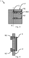
- eine schematische Darstellung einer Ausführungsform einer ersten erfindungsgemäßen bauraumoptimierten Abtrennvorrichtung in einem ersten Zustand von der Rückseite,
- Fig. 4
- eine schematische Darstellung einer Ausführungsform einer ersten erfindungsgemäßen bauraumoptimierten Abtrennvorrichtung in einem ersten Zustand entlang der Schnittlinie A in
Figur 3 , - Fig. 5
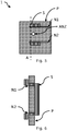
- eine schematische Darstellung einer Ausführungsform einer zweiten erfindungsgemäßen bauraumoptimierten Abtrennvorrichtung in einem ersten Zustand von der Rückseite,
- Fig. 6
- eine schematische Darstellung einer Ausführungsform einer zweiten erfindungsgemäßen bauraumoptimierten Abtrennvorrichtung in einem ersten Zustand entlang der Schnittlinie A in
Figur 5 , - Fig. 7
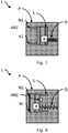
- eine schematische Darstellung einer Ausführungsform einer zweiten erfindungsgemäßen bauraumoptimierten Abtrennvorrichtung in einem ersten Zustand von der Vorderseite, und
- Fig. 8
- eine schematische Darstellung einer Ausführungsform einer ersten erfindungsgemäßen bauraumoptimierten Abtrennvorrichtung in einem zweiten Zustand von der Vorderseite.
- Nachfolgend wird die Erfindung eingehender unter Bezugnahme auf die
Figuren 1-3 dargestellt werden. Dabei ist anzumerken, dass unterschiedliche Aspekte beschrieben werden, die jeweils einzeln oder in Kombination zum Einsatz kommen können. D.h. jeglicher Aspekt kann mit unterschiedlichen Ausführungsformen der Erfindung verwendet werden, soweit nicht explizit als reine Alternative dargestellt. - Weiterhin wird nachfolgend der Einfachheit halber in aller Regel immer nur auf eine Entität Bezug genommen werden. Soweit nicht explizit vermerkt, kann die Erfindung aber auch jeweils mehrere der betroffenen Entitäten aufweisen. Insofern ist die Verwendung der Wörter "ein", "eine" und "eines" nur als Hinweis darauf zu verstehen, dass in einer einfachen Ausführungsform zumindest eine Entität verwendet wird.
- Soweit nachfolgend Verfahren beschrieben werden, sind die einzelnen Schritte eines Verfahrens in beliebiger Reihenfolge anordenbar und/oder kombinierbar, soweit sich durch den Zusammenhang nicht explizit etwas Abweichendes ergibt. Weiterhin sind die Verfahren - soweit nicht ausdrücklich anderweitig gekennzeichnet - untereinander kombinierbar.
- Angaben mit Zahlenwerten sind in aller Regel nicht als exakte Werte zu verstehen, sondern beinhalten auch eine Toleranz von +/- 1% bis zu +/- 10 %.
- Bezugnahme auf Standards oder Spezifikationen oder Normen sind als Bezugnahme auf Standards bzw. Spezifikationen bzw. Normen, die zum Zeitpunkt der Anmeldung und/oder - soweit eine Priorität beansprucht wird - zum Zeitpunkt der Prioritätsanmeldung gelten / galten zu verstehen. Hiermit ist jedoch kein genereller Ausschluss der Anwendbarkeit auf nachfolgende oder ersetzende Standards oder Spezifikationen oder Normen zu verstehen.
- Benachbart schließt im nachfolgend explizit eine unmittelbare Nachbarschaftsbeziehung ein ohne jedoch hierauf beschränkt zu sein. Zwischen schließt im nachfolgenden explizit eine Lage ein, in der das zwischenliegende Teil eine unmittelbare Nachbarschaft zu den umgebenden Teilen aufweist.
- In
Figuren 1-4 ist eine erste Ausführungsform und inFiguren 5-8 eine zweite Ausführungsform einer erfindungsgemäßen bauraumoptimierte Abtrennvorrichtung 1 gezeigt. - Allen Ausführungsformen einer erfindungsgemäßen bauraumoptimierten Abtrennvorrichtung 1 ist gemein, dass sie einen Träger P mit einem elektrischen Bauelement B aufweist.
- Das elektrische Bauelement B kann insbesondere ein Überspannungsschutzelement aufweisen. Der Träger P kann z.B. eine Platine sein bzw. ein Platinenmaterial aufweisen. In aller Regel wird der Träger im Wesentlichen starr sein.
- Zweck der erfindungsgemäßen bauraumoptimierten Abtrennvorrichtung 1 ist es das elektrische Bauteil B bei unzulässiger Erwärmung abzutrennen.
- Der Träger P weist zumindest zwei Führungsnuten N1, N2 auf. Diese Führungsnuten N1, N2 können z.B. mittels Stanzen, Laserbearbeitung, Fräsen etc. in den Träger P eingebracht sein.
- Das elektrische Bauelement B ist auf dem Träger P mit einer thermisch erweichbaren Fixierung befestigt. Beispielsweise kann die thermisch erweichbare Fixierung ein Lot und/oder einen Kleber aufweisen. Weist die thermische erweichbare Fixierung ein Lot auf, so kann z.B. das elektrische Bauelement B Anschlüsse zur Oberflächenmontage für Leiterbahnen des Trägers P aufweisen. Andererseits ist es auch möglich alternativ oder zusätzlich das elektrische Bauelement B mit einem thermisch erweichbaren Kleber auf dem Träger P zu fixieren. Wird z.B. sowohl ein thermisch erweichbares Lot zur elektrischen Verbindung von (oberflächenmontierten) Anschlüssen als auch ein thermisch erweichbarer Kleber eingesetzt, so kann durch die Wahl der Materialen der Erweichungspunkt beeinflusst werden. Werden z.B. ein niedrigschmelzendes Lot und ein bei einer höheren Temperatur erweichbarer Kleber, so kann sich das elektrische Bauelement B und mit ihm auch das Lot auf Temperaturen erwärmen, die über dem Erweichungspunkt des Lotes aber unter dem Erweichungspunkt des Klebers liegen. Das Lot stellt in diesem Fall dennoch die elektrische Verbindung weiterhin her, da es auf Grund der Oberflächenkräfte am Kontakt verbleibt.
- Wie in den
Figuren 1, 2 ,7 und 8 gezeigt, ist relativ zu dem elektrischen Bauelement B ein Kraftspeicher D angeordnet, der - wenn die thermisch erweichbare Fixierung erweicht - das elektrische Bauelement B im Wesentlichen parallel zum Träger P verschiebt und dabei das elektrische Bauelement B abtrennt. - Dieser Verschiebungsprozess ist aus
Figur 2 im Vergleich zuFigur 1 und ausFigur 8 im Vergleich zuFigur 7 ersichtlich. - Der Kraftspeicher D kann z.B. eine Feder (wie dargestellt) oder ein Federbügel, eine komprimiertes Elastomer, etc. sein. In aller Regel übt der Kraftspeicher D nach Montage eine kontinuierliche Kraft aus, die im Falle, dass die Fixierung erweicht zu einer Bewegung führt. Obwohl in den Figuren eine Verschiebung durch Druck gezeigt ist, ist die Erfindung nicht hierauf beschränkt. Gleichfalls ist es möglich, dass ein Zug ausgeübt wird, wobei dann konstruktive Maßnahmen zur mittelbaren / unmittelbaren Befestigung am elektrischen Bauelement B bzw. dem mechanisch verschiebbaren Anzeigemittel S getroffen werden sollten.
- Allen Ausführungsformen einer erfindungsgemäßen bauraumoptimierten Abtrennvorrichtung 1 ist weiterhin gemein, dass sie ein mechanisch verschiebbares Anzeigemittel S aufweisen, wobei das mechanisch verschiebbare Anzeigemittel S anzeigt, dass das zu überwachende elektrische Bauelement B abgetrennt wurde, wobei das mechanisch verschiebbare Anzeigemittel S zusammen mit dem abtrennenden elektrische Bauelement verschoben wird.
- Dazu kann das mechanisch verschiebbare Anzeigemittel S, wie in
Figur 1 und 2 gezeigt, das elektrische Bauelement B seitlich, d.h. in einer Ebene parallel zum Träger P einfassen, oder aber, wie inFigur 7 und 8 gezeigt, teilweisen einfassen. D.h. während inFigur 1 und 2 der Kraftspeicher D mittelbar über das mechanisch verschiebbare Anzeigemittel S verschoben werden kann, verschiebt inFigur 7 und 8 der Kraftspeicher D über das elektrische Bauelement B das mechanisch verschiebbare Anzeigemittel S. Ohne Beschränkung der Allgemeinheit kann natürlich auch vorgesehen sein, dass das mechanisch verschiebbare Anzeigemittel S das elektrische Bauelement haubenartig überdeckt. Weiterhin ohne Beschränkung der Allgemeinheit kann natürlich auch vorgesehen sein, dass das mechanisch verschiebbare Anzeigemittel S weitere Eigenschaften aufweist, wie z.B. Löscheigenschaften, z.B. in dem es hartgasendes Material aufweist. Weiterhin kann auch vorgesehen sein, dass die Gestaltung des mechanischen Anzeigemittels S im ausgelösten Zustand einen möglichen Lichtbogenpfad einengt und/oder verlängert. Zudem kann vorgesehen sein, dass das mechanische Anzeigemittel S auch als Kühlkörper für das elektrische Bauelement B fungiert. - Das mechanisch verschiebbare Anzeigemittel S wird in den zumindest zwei Führungsnuten N1, N2 gehalten und geführt.
- Dabei unterscheidet sich die Anordnung der ersten Ausführungsform von der zweiten Ausführungsform darin, dass die Halterung dadurch erzielt wird, dass die in der Ausführungsform der
Figur 4 eine nach innen gerichtete Umgreifung angezeigt ist, während inFigur 6 eine nach außen gerichtete Umgreifung angezeigt ist. Es sei angemerkt, dass auch eine gleichgerichtete Umgreifung möglich ist. - Solche Umgreifungen können als Formteile vorgesehen sein, die bei der Montage des mechanisch verschiebbaren Anzeigemittels S durch die Führungsnuten N1, N2 federnd und/oder pressen hindurchgeführt werden, und die nach dem Durchführen wieder expandieren. D.h. das mechanisch verschiebbare Anzeigemittels S kann z.B. aufgerastet werden. Es ist aber auch möglich durch einen Biegeprozess nach dem Einstecken in die Führungsnuten N1, N2 Umgreifungen an dem mechanisch verschiebbaren Anzeigemittel S zu formen.
- D.h. nunmehr kann eine Abtrennvorrichtung 1 nach der Montage des elektrischen Bauelementes B auf dem Träger P montiert werden, ohne dass die Gefahr besteht, dass Elemente verrutschen können. Nach und/oder während der Montage des mechanisch verschiebbaren Anzeigemittels S kann der Kraftspeicher D eingesetzt werden.
- D.h. erwärmt sich das elektrische Bauelement B, wird das elektrische Bauelement B nach Freigabe des Kraftspeichers D, z.B. im Fehlerfall, entlang der Oberfläche des Trägers P verschoben. Der Verfahrweg des elektrischen Bauelements B kann dabei genutzt werden um gleichzeitig eine mechanische Anzeige zu realisieren.
- Durch die Erfindung wird es ermöglicht eine einfach und sicher und kostengünstig Abtrennvorrichtung herzustellen, die wenig Bauraum beansprucht und zudem eine Abtrennung signalisieren können.
- In allen Ausführungsformen ist es zudem möglich, dass das mechanisch verschiebbare Anzeigemittel S eine Einrichtung zur Fixierung des mechanisch verschiebbaren Anzeigemittels S in einer Ausgangsposition aufweist.
- Diese Fixierung wird bevorzugt durch das zuvor fixierte elektrische Bauelement B zur Verfügung gestellt. D.h. der Herstellungsprozess kann weiter vereinfacht werden und die Auslösesicherheit erhöht werden.
- In allen Ausführungsformen ist es zudem möglich, dass die Abtrennvorrichtung 1 für ein abgetrenntes zu überwachendes elektrisches Bauelement B eine Einrichtung zur Fixierung in einem abgetrennten Zustand aufweist.
- Hierdurch kann verhindert werden, dass das abgetrennte elektrische Bauelement B sich lose in einem Gehäuse befindet, und dort möglicherweise mechanische Funktionen beeinträchtigen könnte oder aber elektrische Verbindungen an anderen Orten hervorrufen könnte. Beispielsweise kann ein haubenartiges mechanisch verschiebbaren Anzeigemittel S und der Träger P (und eventuell in Verbindung mit dem Kraftspeicher D) das abgetrennte elektrische Bauelement B fixieren. Durch die zuvor beschriebene Anordnung ist es möglich Geräte mit elektrischem Bauelemente B und einer erfindungsgemäßen Abtrennvorrichtung zu realisiert, die bauartbedingt keine stützende Gehäusewand besitzen. Umfasst das mechanisch verschiebbaren Anzeigemittel S das abgetrennte elektrische Bauelement B lediglich seitlich kann durch ein Gehäuseabschnitt parallel zum Träger P ein Vagabundieren des elektrische Bauelements B normal zum Träger P verhindert werden.
- In allen Ausführungsformen ist es zudem möglich, dass das mechanisch verschiebbare Anzeigemittel S einen Farbwechsel und/oder eine Transmissionsänderung zur Verfügung stellt. Beispielsweise kann hierzu in einem Gehäuse und/oder im Träger P eine Öffnung ANZ vorgesehen sein, in der ein Farbwechselfeld mit/auf dem mechanisch verschiebbaren Anzeigemittel S verschoben wird, wenn das elektrische Bauelement B abgetrennt wird. D.h. es kann z.B. ein Farbwechsel von Grün nach Rot eine erfolgte Abtrennung signalisieren.
- In den
Figuren 1-4 ist z.B. eine Ausführungsform gezeigt, bei der eine Öffnung ANZ im Träger P durch das mechanische Anzeigemittel S verdeckt (Fig. 2 ) werden kann. In denFiguren 5-8 hingegen ist eine Ausführungsform gezeigt, bei der eine Öffnung ANZ im Träger P durch das mechanische Anzeigemittel S geöffnet (Fig. 8 ) werden kann. - In allen Ausführungsformen ist es zudem möglich, dass die Abtrennvorrichtung 1 Einrichtungen zur Montage auf eine Tragschiene aufweist.
- D.h. durch geeignete Gehäuse mit den entsprechenden Einrichtungen kann eine Abtrennvorrichtung 1 gemäß der Erfindung auch in Schaltschränken verbaut sein.
- Auch wenn zuvor die Erfindung in Bezug auf allgemeine elektrische Bauelemente B beschrieben wurde, so ist sie von besonderer Bedeutung für besonders thermisch anfällige Bauelemente. Hierzu zählen Halbleiter, Transistoren, Widerstände, Varistoren, TVS-Dioden oder gasgefüllte Überspannungsableiter.
- Obwohl in den Figuren gerade Führungsnuten N1, N2 gezeigt sind, ist die Erfindung nicht hierauf beschränkt. Vielmehr sind dem Fachmann hierdurch keine Grenzen gesetzt. Jedoch erlauben im Wesentlichen gerade Führungsnuten N1, N2 eine besonders einfache Bewegung.
- Obwohl vorstehend Bezug auf ein Bauelement B genommen wurde, kann die Erfindung in gleicher Weise auf eine Vielzahl von Bauelemente angewandt werden.
-
- 1
- Bauraumoptimierte Abtrennvorrichtung
- P
- Träger
- B
- elektrisches Bauelement
- N1, N2
- Führungsnuten
- D
- Kraftspeicher
- S
- mechanisch verschiebbares Anzeigemittel
- ANZ
- Öffnung
Claims (10)
- Bauraumoptimierte Abtrennvorrichtung (1), aufweisend• einen Träger (P) mit einem elektrischen Bauelement (B), wobei das Bauteil (B) bei unzulässiger Erwärmung abzutrennen ist,• wobei der Träger (P) zumindest zwei Führungsnuten (N1, N2) aufweist,• wobei das elektrische Bauelement (B) auf einem Träger (P) mit einer thermisch erweichbaren Fixierung befestigt ist,• wobei relativ zu dem elektrischen Bauelement ein Kraftspeicher (D) angeordnet ist, der - wenn die thermisch erweichbare Fixierung erweicht - das elektrische Bauelement im Wesentlichen parallel zum Träger (P) verschiebt und dabei das elektrische Bauelement (B) abtrennt,• weiterhin ein mechanisch verschiebbares Anzeigemittel (S) aufweisend, wobei das mechanisch verschiebbare Anzeigemittel anzeigt, dass das zu überwachende elektrische Bauelement (B) abgetrennt wurde, wobei das mechanisch verschiebbare Anzeigemittel (S) zusammen mit dem abtrennenden elektrische Bauelement verschoben wird,• wobei das mechanisch verschiebbare Anzeigemittel (S) in den zumindest zwei Führungsnuten (N1, N2) gehalten und geführt wird.
- Vorrichtung nach Anspruch 1, dadurch gekennzeichnet, dass das mechanisch verschiebbare Anzeigemittel (S) eine Einrichtung zur Fixierung des mechanisch verschiebbaren Anzeigemittels (S) in einer Ausgangsposition aufweist.
- Vorrichtung nach Anspruch 1 oder 2, dadurch gekennzeichnet, dass die Abtrennvorrichtung für ein abgetrenntes zu überwachendes elektrische Bauelement eine Einrichtung zur Fixierung in einem abgetrennten Zustand aufweist.
- Vorrichtung nach einem der vorhergehenden Ansprüche, dadurch gekennzeichnet, dass der Kraftspeicher (D) eine Feder aufweist.
- Vorrichtung nach einem der vorhergehenden Ansprüche, dadurch gekennzeichnet, dass das mechanisch verschiebbare Anzeigemittel (S) einen Farbwechsel und/oder eine Transmissionsänderung zur Verfügung stellt.
- Vorrichtung nach Anspruch 5, dass das mechanische Anzeigemittel (S) im Falle einer Verschiebung eine Öffnung (ANZ) im Träger (P) verdeckt oder öffnet.
- Vorrichtung nach einem der vorhergehenden Ansprüche, dadurch gekennzeichnet, dass die bauraumoptimierte Abtrennvorrichtung Einrichtungen zur Montage auf eine Tragschiene aufweist.
- Vorrichtung nach einem der vorhergehenden Ansprüche, dadurch gekennzeichnet, dass das elektrische Bauelemente ausgewählt ist aus einer Gruppe aufweisend Halbleiter, Transistoren, Widerstände, Varistoren, TVS-Dioden oder gasgefüllte Überspannungsableiter.
- Vorrichtung nach einem der vorhergehenden Ansprüche, dadurch gekennzeichnet, dass die thermisch erweichbare Fixierung ein Lot und/oder einen Kleber aufweist.
- Vorrichtung nach einem der vorhergehenden Ansprüche, dadurch gekennzeichnet, dass der Träger (P) ein Platinenmaterial aufweist.
Priority Applications (1)
| Application Number | Priority Date | Filing Date | Title |
|---|---|---|---|
| SI201930017T SI3605574T1 (sl) | 2018-07-30 | 2019-07-30 | Ločevalna naprava z optimiziranim instalacijskim območjem |
Applications Claiming Priority (1)
| Application Number | Priority Date | Filing Date | Title |
|---|---|---|---|
| DE102018212690.9A DE102018212690A1 (de) | 2018-07-30 | 2018-07-30 | Bauraumoptimierte Abtrennvorrichtung |
Publications (2)
| Publication Number | Publication Date |
|---|---|
| EP3605574A1 true EP3605574A1 (de) | 2020-02-05 |
| EP3605574B1 EP3605574B1 (de) | 2020-11-25 |
Family
ID=67438287
Family Applications (1)
| Application Number | Title | Priority Date | Filing Date |
|---|---|---|---|
| EP19188998.9A Active EP3605574B1 (de) | 2018-07-30 | 2019-07-30 | Bauraumoptimierte abtrennvorrichtung |
Country Status (4)
| Country | Link |
|---|---|
| EP (1) | EP3605574B1 (de) |
| CN (1) | CN210156315U (de) |
| DE (1) | DE102018212690A1 (de) |
| SI (1) | SI3605574T1 (de) |
Families Citing this family (1)
| Publication number | Priority date | Publication date | Assignee | Title |
|---|---|---|---|---|
| DE102023125692B3 (de) | 2023-09-21 | 2024-12-05 | Günther Spelsberg GmbH & Co. Kommanditgesellschaft | Elektrische Verbindungsvorrichtung mit Sicherungselement |
Citations (12)
| Publication number | Priority date | Publication date | Assignee | Title |
|---|---|---|---|---|
| DE9010246U1 (de) | 1990-07-06 | 1990-10-31 | CITEL 2CP S.A., Nederweert | Überspannungsschutzvorrichtung |
| DE4241311C2 (de) | 1992-12-08 | 1995-06-08 | Phoenix Contact Gmbh & Co | Temperaturschalter mit einem Bausteingehäuse |
| US5831507A (en) * | 1996-09-09 | 1998-11-03 | Toyo System Co., Ltd. | Dual-functional fuse unit that is responsive to electric current and ambient temperature |
| US6430019B1 (en) | 1998-06-08 | 2002-08-06 | Ferraz S.A. | Circuit protection device |
| DE69904274T2 (de) | 1998-09-15 | 2003-08-28 | Soule Materiel Electrique, Bagneres-De-Bigorre | Schutzvorrichtung für elektrischen Anlagen gegen Speisungsstörungen |
| DE102005040308A1 (de) | 2005-08-24 | 2007-03-01 | Wehrle Autoelektronik Gmbh | Thermosicherung, insbesondere für ein Leistungsmodul eines Kraftfahrzeugs, sowie Leistungsmodul mit einer derartigen Thermosicherung |
| DE102006042028B3 (de) * | 2006-07-19 | 2007-09-27 | Dehn + Söhne Gmbh + Co. Kg | Abtrennvorrichtung für insbesondere steckbare Überspannungsableiter |
| DE102008057166A1 (de) | 2008-11-13 | 2010-05-20 | Behr-Hella Thermocontrol Gmbh | Elektrische Schaltung mit Übertemperaturschutz |
| DE102009036578B3 (de) | 2009-08-07 | 2010-09-09 | Magna Electronics Europe Gmbh & Co.Kg | Thermosicherung, insbesondere für ein Leistungsmodul eines Kraftfahrzeugs, sowie Leisstungsmodul mit einer derartigen Thermosicherung |
| WO2011011985A1 (zh) * | 2009-07-27 | 2011-02-03 | 佛山市浦斯电子有限公司 | 一种具有热保护装置的电涌保护器 |
| DE102015213050A1 (de) * | 2015-07-13 | 2017-01-19 | Phoenix Contact Gmbh & Co. Kg | Varistor mit einer Abtrennvorrichtung |
| DE202016102862U1 (de) | 2016-05-31 | 2017-09-03 | Phoenix Contact Gmbh & Co. Kg | Bauraumoptimierte Abtrennvorrichtung |
Family Cites Families (2)
| Publication number | Priority date | Publication date | Assignee | Title |
|---|---|---|---|---|
| US9455106B2 (en) * | 2011-02-02 | 2016-09-27 | Littelfuse, Inc. | Three-function reflowable circuit protection device |
| DE102014008366B3 (de) * | 2014-06-04 | 2015-10-22 | Dehn + Söhne Gmbh + Co. Kg | Vorrichtung zum thermischen Auslösen oder Abtrennen eines Überspannungsschutzgerätes |
-
2018
- 2018-07-30 DE DE102018212690.9A patent/DE102018212690A1/de not_active Ceased
-
2019
- 2019-07-26 CN CN201921186194.3U patent/CN210156315U/zh active Active
- 2019-07-30 SI SI201930017T patent/SI3605574T1/sl unknown
- 2019-07-30 EP EP19188998.9A patent/EP3605574B1/de active Active
Patent Citations (12)
| Publication number | Priority date | Publication date | Assignee | Title |
|---|---|---|---|---|
| DE9010246U1 (de) | 1990-07-06 | 1990-10-31 | CITEL 2CP S.A., Nederweert | Überspannungsschutzvorrichtung |
| DE4241311C2 (de) | 1992-12-08 | 1995-06-08 | Phoenix Contact Gmbh & Co | Temperaturschalter mit einem Bausteingehäuse |
| US5831507A (en) * | 1996-09-09 | 1998-11-03 | Toyo System Co., Ltd. | Dual-functional fuse unit that is responsive to electric current and ambient temperature |
| US6430019B1 (en) | 1998-06-08 | 2002-08-06 | Ferraz S.A. | Circuit protection device |
| DE69904274T2 (de) | 1998-09-15 | 2003-08-28 | Soule Materiel Electrique, Bagneres-De-Bigorre | Schutzvorrichtung für elektrischen Anlagen gegen Speisungsstörungen |
| DE102005040308A1 (de) | 2005-08-24 | 2007-03-01 | Wehrle Autoelektronik Gmbh | Thermosicherung, insbesondere für ein Leistungsmodul eines Kraftfahrzeugs, sowie Leistungsmodul mit einer derartigen Thermosicherung |
| DE102006042028B3 (de) * | 2006-07-19 | 2007-09-27 | Dehn + Söhne Gmbh + Co. Kg | Abtrennvorrichtung für insbesondere steckbare Überspannungsableiter |
| DE102008057166A1 (de) | 2008-11-13 | 2010-05-20 | Behr-Hella Thermocontrol Gmbh | Elektrische Schaltung mit Übertemperaturschutz |
| WO2011011985A1 (zh) * | 2009-07-27 | 2011-02-03 | 佛山市浦斯电子有限公司 | 一种具有热保护装置的电涌保护器 |
| DE102009036578B3 (de) | 2009-08-07 | 2010-09-09 | Magna Electronics Europe Gmbh & Co.Kg | Thermosicherung, insbesondere für ein Leistungsmodul eines Kraftfahrzeugs, sowie Leisstungsmodul mit einer derartigen Thermosicherung |
| DE102015213050A1 (de) * | 2015-07-13 | 2017-01-19 | Phoenix Contact Gmbh & Co. Kg | Varistor mit einer Abtrennvorrichtung |
| DE202016102862U1 (de) | 2016-05-31 | 2017-09-03 | Phoenix Contact Gmbh & Co. Kg | Bauraumoptimierte Abtrennvorrichtung |
Also Published As
| Publication number | Publication date |
|---|---|
| DE102018212690A1 (de) | 2020-01-30 |
| SI3605574T1 (sl) | 2021-07-30 |
| EP3605574B1 (de) | 2020-11-25 |
| CN210156315U (zh) | 2020-03-17 |
Similar Documents
| Publication | Publication Date | Title |
|---|---|---|
| DE69904274T2 (de) | Schutzvorrichtung für elektrischen Anlagen gegen Speisungsstörungen | |
| DE102014008366B3 (de) | Vorrichtung zum thermischen Auslösen oder Abtrennen eines Überspannungsschutzgerätes | |
| WO2013167253A1 (de) | Elektrische reihenklemme | |
| DE102011053414A1 (de) | Thermische Abtrennvorrichtung für Überspannungsschutzgeräte | |
| DE202014103262U1 (de) | Überspannungsschutzelement | |
| DE202010017932U1 (de) | Überspannungsschutzelement | |
| WO2002033721A1 (de) | Überlastschutz für elektrische maschinen | |
| EP3245661A1 (de) | Schmelzsicherungsbauelement | |
| DE102008029670A1 (de) | Überspannungsschutzelement | |
| EP3128624B1 (de) | Überspannungsschutzgeräteensemble | |
| DE202009013505U1 (de) | Überspannungsschutzelement | |
| EP3745432B1 (de) | Überlastschutzanordnung | |
| EP3605574B1 (de) | Bauraumoptimierte abtrennvorrichtung | |
| EP2280457A2 (de) | Überspannungsschutzelement | |
| DE202016102520U1 (de) | Kostengünstige thermische Abtrennvorrichtung für eine elektrische Komponente | |
| DE202010014430U1 (de) | Überspannungsschutzelement und elektrisches Gerät | |
| DE102017218582B4 (de) | Bauraumbegrenztes Schutzmodul mit zumindest zwei Überspannungsschutzelementen in parallelen Stromzweigen | |
| DE102015014163A1 (de) | Vorrichtung zum thermischen Auslösen, Abtrennen und/oder Signalisieren des Zustandes eines Überspannungsschutzgerätes | |
| DE102017131154B4 (de) | Überspannungsschutzanordnung | |
| DE102017113852A1 (de) | Überspannungsschutzelement | |
| DE202016102862U1 (de) | Bauraumoptimierte Abtrennvorrichtung | |
| DE102013214194B4 (de) | Bauraumbegrenzte Überspannungsschutzvorrichtung und Verfahren zu dessen Herstellung | |
| DE202019103666U1 (de) | Überspannungsschutzelement und Überspannungsschutzgerät | |
| DE102018220149B3 (de) | Baugruppe mit einem elektrotechnischen Bauelement auf einem Träger | |
| DE102018129679A1 (de) | Überspannungsschutzvorrichtung mit thermischer Überlastschutzvorrichtung |
Legal Events
| Date | Code | Title | Description |
|---|---|---|---|
| PUAI | Public reference made under article 153(3) epc to a published international application that has entered the european phase |
Free format text: ORIGINAL CODE: 0009012 |
|
| STAA | Information on the status of an ep patent application or granted ep patent |
Free format text: STATUS: REQUEST FOR EXAMINATION WAS MADE |
|
| 17P | Request for examination filed |
Effective date: 20190730 |
|
| AK | Designated contracting states |
Kind code of ref document: A1 Designated state(s): AL AT BE BG CH CY CZ DE DK EE ES FI FR GB GR HR HU IE IS IT LI LT LU LV MC MK MT NL NO PL PT RO RS SE SI SK SM TR |
|
| AX | Request for extension of the european patent |
Extension state: BA ME |
|
| RBV | Designated contracting states (corrected) |
Designated state(s): AL AT BE BG CH CY CZ DE DK EE ES FI FR GB GR HR HU IE IS IT LI LT LU LV MC MK MT NL NO PL PT RO RS SE SI SK SM TR |
|
| RIC1 | Information provided on ipc code assigned before grant |
Ipc: H01H 37/76 20060101ALI20200709BHEP Ipc: H01H 9/18 20060101AFI20200709BHEP |
|
| GRAP | Despatch of communication of intention to grant a patent |
Free format text: ORIGINAL CODE: EPIDOSNIGR1 |
|
| STAA | Information on the status of an ep patent application or granted ep patent |
Free format text: STATUS: GRANT OF PATENT IS INTENDED |
|
| INTG | Intention to grant announced |
Effective date: 20200914 |
|
| GRAS | Grant fee paid |
Free format text: ORIGINAL CODE: EPIDOSNIGR3 |
|
| GRAA | (expected) grant |
Free format text: ORIGINAL CODE: 0009210 |
|
| STAA | Information on the status of an ep patent application or granted ep patent |
Free format text: STATUS: THE PATENT HAS BEEN GRANTED |
|
| AK | Designated contracting states |
Kind code of ref document: B1 Designated state(s): AL AT BE BG CH CY CZ DE DK EE ES FI FR GB GR HR HU IE IS IT LI LT LU LV MC MK MT NL NO PL PT RO RS SE SI SK SM TR |
|
| REG | Reference to a national code |
Ref country code: GB Ref legal event code: FG4D Free format text: NOT ENGLISH |
|
| REG | Reference to a national code |
Ref country code: CH Ref legal event code: EP |
|
| REG | Reference to a national code |
Ref country code: AT Ref legal event code: REF Ref document number: 1339242 Country of ref document: AT Kind code of ref document: T Effective date: 20201215 |
|
| REG | Reference to a national code |
Ref country code: DE Ref legal event code: R096 Ref document number: 502019000451 Country of ref document: DE |
|
| REG | Reference to a national code |
Ref country code: IE Ref legal event code: FG4D Free format text: LANGUAGE OF EP DOCUMENT: GERMAN |
|
| REG | Reference to a national code |
Ref country code: NL Ref legal event code: MP Effective date: 20201125 |
|
| PG25 | Lapsed in a contracting state [announced via postgrant information from national office to epo] |
Ref country code: GR Free format text: LAPSE BECAUSE OF FAILURE TO SUBMIT A TRANSLATION OF THE DESCRIPTION OR TO PAY THE FEE WITHIN THE PRESCRIBED TIME-LIMIT Effective date: 20210226 Ref country code: NO Free format text: LAPSE BECAUSE OF FAILURE TO SUBMIT A TRANSLATION OF THE DESCRIPTION OR TO PAY THE FEE WITHIN THE PRESCRIBED TIME-LIMIT Effective date: 20210225 Ref country code: FI Free format text: LAPSE BECAUSE OF FAILURE TO SUBMIT A TRANSLATION OF THE DESCRIPTION OR TO PAY THE FEE WITHIN THE PRESCRIBED TIME-LIMIT Effective date: 20201125 Ref country code: PT Free format text: LAPSE BECAUSE OF FAILURE TO SUBMIT A TRANSLATION OF THE DESCRIPTION OR TO PAY THE FEE WITHIN THE PRESCRIBED TIME-LIMIT Effective date: 20210325 Ref country code: RS Free format text: LAPSE BECAUSE OF FAILURE TO SUBMIT A TRANSLATION OF THE DESCRIPTION OR TO PAY THE FEE WITHIN THE PRESCRIBED TIME-LIMIT Effective date: 20201125 |
|
| PG25 | Lapsed in a contracting state [announced via postgrant information from national office to epo] |
Ref country code: SE Free format text: LAPSE BECAUSE OF FAILURE TO SUBMIT A TRANSLATION OF THE DESCRIPTION OR TO PAY THE FEE WITHIN THE PRESCRIBED TIME-LIMIT Effective date: 20201125 Ref country code: LV Free format text: LAPSE BECAUSE OF FAILURE TO SUBMIT A TRANSLATION OF THE DESCRIPTION OR TO PAY THE FEE WITHIN THE PRESCRIBED TIME-LIMIT Effective date: 20201125 Ref country code: IS Free format text: LAPSE BECAUSE OF FAILURE TO SUBMIT A TRANSLATION OF THE DESCRIPTION OR TO PAY THE FEE WITHIN THE PRESCRIBED TIME-LIMIT Effective date: 20210325 Ref country code: PL Free format text: LAPSE BECAUSE OF FAILURE TO SUBMIT A TRANSLATION OF THE DESCRIPTION OR TO PAY THE FEE WITHIN THE PRESCRIBED TIME-LIMIT Effective date: 20201125 Ref country code: BG Free format text: LAPSE BECAUSE OF FAILURE TO SUBMIT A TRANSLATION OF THE DESCRIPTION OR TO PAY THE FEE WITHIN THE PRESCRIBED TIME-LIMIT Effective date: 20210225 |
|
| REG | Reference to a national code |
Ref country code: LT Ref legal event code: MG9D |
|
| PG25 | Lapsed in a contracting state [announced via postgrant information from national office to epo] |
Ref country code: HR Free format text: LAPSE BECAUSE OF FAILURE TO SUBMIT A TRANSLATION OF THE DESCRIPTION OR TO PAY THE FEE WITHIN THE PRESCRIBED TIME-LIMIT Effective date: 20201125 |
|
| PG25 | Lapsed in a contracting state [announced via postgrant information from national office to epo] |
Ref country code: RO Free format text: LAPSE BECAUSE OF FAILURE TO SUBMIT A TRANSLATION OF THE DESCRIPTION OR TO PAY THE FEE WITHIN THE PRESCRIBED TIME-LIMIT Effective date: 20201125 Ref country code: LT Free format text: LAPSE BECAUSE OF FAILURE TO SUBMIT A TRANSLATION OF THE DESCRIPTION OR TO PAY THE FEE WITHIN THE PRESCRIBED TIME-LIMIT Effective date: 20201125 Ref country code: CZ Free format text: LAPSE BECAUSE OF FAILURE TO SUBMIT A TRANSLATION OF THE DESCRIPTION OR TO PAY THE FEE WITHIN THE PRESCRIBED TIME-LIMIT Effective date: 20201125 Ref country code: EE Free format text: LAPSE BECAUSE OF FAILURE TO SUBMIT A TRANSLATION OF THE DESCRIPTION OR TO PAY THE FEE WITHIN THE PRESCRIBED TIME-LIMIT Effective date: 20201125 Ref country code: SK Free format text: LAPSE BECAUSE OF FAILURE TO SUBMIT A TRANSLATION OF THE DESCRIPTION OR TO PAY THE FEE WITHIN THE PRESCRIBED TIME-LIMIT Effective date: 20201125 Ref country code: SM Free format text: LAPSE BECAUSE OF FAILURE TO SUBMIT A TRANSLATION OF THE DESCRIPTION OR TO PAY THE FEE WITHIN THE PRESCRIBED TIME-LIMIT Effective date: 20201125 |
|
| REG | Reference to a national code |
Ref country code: DE Ref legal event code: R097 Ref document number: 502019000451 Country of ref document: DE |
|
| PG25 | Lapsed in a contracting state [announced via postgrant information from national office to epo] |
Ref country code: DK Free format text: LAPSE BECAUSE OF FAILURE TO SUBMIT A TRANSLATION OF THE DESCRIPTION OR TO PAY THE FEE WITHIN THE PRESCRIBED TIME-LIMIT Effective date: 20201125 |
|
| PLBE | No opposition filed within time limit |
Free format text: ORIGINAL CODE: 0009261 |
|
| STAA | Information on the status of an ep patent application or granted ep patent |
Free format text: STATUS: NO OPPOSITION FILED WITHIN TIME LIMIT |
|
| PG25 | Lapsed in a contracting state [announced via postgrant information from national office to epo] |
Ref country code: IT Free format text: LAPSE BECAUSE OF FAILURE TO SUBMIT A TRANSLATION OF THE DESCRIPTION OR TO PAY THE FEE WITHIN THE PRESCRIBED TIME-LIMIT Effective date: 20201125 Ref country code: NL Free format text: LAPSE BECAUSE OF FAILURE TO SUBMIT A TRANSLATION OF THE DESCRIPTION OR TO PAY THE FEE WITHIN THE PRESCRIBED TIME-LIMIT Effective date: 20201125 Ref country code: AL Free format text: LAPSE BECAUSE OF FAILURE TO SUBMIT A TRANSLATION OF THE DESCRIPTION OR TO PAY THE FEE WITHIN THE PRESCRIBED TIME-LIMIT Effective date: 20201125 |
|
| 26N | No opposition filed |
Effective date: 20210826 |
|
| PG25 | Lapsed in a contracting state [announced via postgrant information from national office to epo] |
Ref country code: ES Free format text: LAPSE BECAUSE OF FAILURE TO SUBMIT A TRANSLATION OF THE DESCRIPTION OR TO PAY THE FEE WITHIN THE PRESCRIBED TIME-LIMIT Effective date: 20201125 |
|
| PG25 | Lapsed in a contracting state [announced via postgrant information from national office to epo] |
Ref country code: MC Free format text: LAPSE BECAUSE OF FAILURE TO SUBMIT A TRANSLATION OF THE DESCRIPTION OR TO PAY THE FEE WITHIN THE PRESCRIBED TIME-LIMIT Effective date: 20201125 |
|
| REG | Reference to a national code |
Ref country code: BE Ref legal event code: MM Effective date: 20210731 |
|
| PG25 | Lapsed in a contracting state [announced via postgrant information from national office to epo] |
Ref country code: LU Free format text: LAPSE BECAUSE OF NON-PAYMENT OF DUE FEES Effective date: 20210730 |
|
| PG25 | Lapsed in a contracting state [announced via postgrant information from national office to epo] |
Ref country code: IE Free format text: LAPSE BECAUSE OF NON-PAYMENT OF DUE FEES Effective date: 20210730 Ref country code: BE Free format text: LAPSE BECAUSE OF NON-PAYMENT OF DUE FEES Effective date: 20210731 |
|
| REG | Reference to a national code |
Ref country code: CH Ref legal event code: PL |
|
| PG25 | Lapsed in a contracting state [announced via postgrant information from national office to epo] |
Ref country code: LI Free format text: LAPSE BECAUSE OF NON-PAYMENT OF DUE FEES Effective date: 20220731 Ref country code: CH Free format text: LAPSE BECAUSE OF NON-PAYMENT OF DUE FEES Effective date: 20220731 |
|
| P01 | Opt-out of the competence of the unified patent court (upc) registered |
Effective date: 20230424 |
|
| PG25 | Lapsed in a contracting state [announced via postgrant information from national office to epo] |
Ref country code: CY Free format text: LAPSE BECAUSE OF FAILURE TO SUBMIT A TRANSLATION OF THE DESCRIPTION OR TO PAY THE FEE WITHIN THE PRESCRIBED TIME-LIMIT Effective date: 20201125 |
|
| PG25 | Lapsed in a contracting state [announced via postgrant information from national office to epo] |
Ref country code: HU Free format text: LAPSE BECAUSE OF FAILURE TO SUBMIT A TRANSLATION OF THE DESCRIPTION OR TO PAY THE FEE WITHIN THE PRESCRIBED TIME-LIMIT; INVALID AB INITIO Effective date: 20190730 |
|
| GBPC | Gb: european patent ceased through non-payment of renewal fee |
Effective date: 20230730 |
|
| PG25 | Lapsed in a contracting state [announced via postgrant information from national office to epo] |
Ref country code: MK Free format text: LAPSE BECAUSE OF FAILURE TO SUBMIT A TRANSLATION OF THE DESCRIPTION OR TO PAY THE FEE WITHIN THE PRESCRIBED TIME-LIMIT Effective date: 20201125 Ref country code: GB Free format text: LAPSE BECAUSE OF NON-PAYMENT OF DUE FEES Effective date: 20230730 |
|
| PG25 | Lapsed in a contracting state [announced via postgrant information from national office to epo] |
Ref country code: TR Free format text: LAPSE BECAUSE OF FAILURE TO SUBMIT A TRANSLATION OF THE DESCRIPTION OR TO PAY THE FEE WITHIN THE PRESCRIBED TIME-LIMIT Effective date: 20201125 |
|
| PG25 | Lapsed in a contracting state [announced via postgrant information from national office to epo] |
Ref country code: MT Free format text: LAPSE BECAUSE OF FAILURE TO SUBMIT A TRANSLATION OF THE DESCRIPTION OR TO PAY THE FEE WITHIN THE PRESCRIBED TIME-LIMIT Effective date: 20201125 |
|
| PGFP | Annual fee paid to national office [announced via postgrant information from national office to epo] |
Ref country code: FR Payment date: 20240725 Year of fee payment: 6 |
|
| PGFP | Annual fee paid to national office [announced via postgrant information from national office to epo] |
Ref country code: SI Payment date: 20250716 Year of fee payment: 7 |
|
| REG | Reference to a national code |
Ref country code: AT Ref legal event code: MM01 Ref document number: 1339242 Country of ref document: AT Kind code of ref document: T Effective date: 20240730 |
|
| PGFP | Annual fee paid to national office [announced via postgrant information from national office to epo] |
Ref country code: DE Payment date: 20250926 Year of fee payment: 7 |
|
| PG25 | Lapsed in a contracting state [announced via postgrant information from national office to epo] |
Ref country code: AT Free format text: LAPSE BECAUSE OF NON-PAYMENT OF DUE FEES Effective date: 20240730 |
|
| PGFP | Annual fee paid to national office [announced via postgrant information from national office to epo] |
Ref country code: AT Payment date: 20260410 Year of fee payment: 5 |
|
| PG25 | Lapsed in a contracting state [announced via postgrant information from national office to epo] |
Ref country code: FR Free format text: LAPSE BECAUSE OF NON-PAYMENT OF DUE FEES Effective date: 20250731 |