EP3605574A1 - Dispositif de séparation à encombrement réduit - Google Patents
Dispositif de séparation à encombrement réduit Download PDFInfo
- Publication number
- EP3605574A1 EP3605574A1 EP19188998.9A EP19188998A EP3605574A1 EP 3605574 A1 EP3605574 A1 EP 3605574A1 EP 19188998 A EP19188998 A EP 19188998A EP 3605574 A1 EP3605574 A1 EP 3605574A1
- Authority
- EP
- European Patent Office
- Prior art keywords
- electrical component
- display means
- carrier
- mechanically displaceable
- displaceable display
- Prior art date
- Legal status (The legal status is an assumption and is not a legal conclusion. Google has not performed a legal analysis and makes no representation as to the accuracy of the status listed.)
- Granted
Links
Images

Classifications
-
- H—ELECTRICITY
- H01—ELECTRIC ELEMENTS
- H01H—ELECTRIC SWITCHES; RELAYS; SELECTORS; EMERGENCY PROTECTIVE DEVICES
- H01H9/00—Details of switching devices, not covered by groups H01H1/00 - H01H7/00
- H01H9/18—Distinguishing marks on switches, e.g. for indicating switch location in the dark; Adaptation of switches to receive distinguishing marks
-
- H—ELECTRICITY
- H01—ELECTRIC ELEMENTS
- H01H—ELECTRIC SWITCHES; RELAYS; SELECTORS; EMERGENCY PROTECTIVE DEVICES
- H01H37/00—Thermally-actuated switches
- H01H37/74—Switches in which only the opening movement or only the closing movement of a contact is effected by heating or cooling
- H01H37/76—Contact member actuated by melting of fusible material, actuated due to burning of combustible material or due to explosion of explosive material
- H01H37/761—Contact member actuated by melting of fusible material, actuated due to burning of combustible material or due to explosion of explosive material with a fusible element forming part of the switched circuit
-
- H—ELECTRICITY
- H01—ELECTRIC ELEMENTS
- H01H—ELECTRIC SWITCHES; RELAYS; SELECTORS; EMERGENCY PROTECTIVE DEVICES
- H01H37/00—Thermally-actuated switches
- H01H37/74—Switches in which only the opening movement or only the closing movement of a contact is effected by heating or cooling
- H01H37/76—Contact member actuated by melting of fusible material, actuated due to burning of combustible material or due to explosion of explosive material
- H01H37/761—Contact member actuated by melting of fusible material, actuated due to burning of combustible material or due to explosion of explosive material with a fusible element forming part of the switched circuit
- H01H2037/762—Contact member actuated by melting of fusible material, actuated due to burning of combustible material or due to explosion of explosive material with a fusible element forming part of the switched circuit using a spring for opening the circuit when the fusible element melts
-
- H—ELECTRICITY
- H01—ELECTRIC ELEMENTS
- H01H—ELECTRIC SWITCHES; RELAYS; SELECTORS; EMERGENCY PROTECTIVE DEVICES
- H01H37/00—Thermally-actuated switches
- H01H37/74—Switches in which only the opening movement or only the closing movement of a contact is effected by heating or cooling
- H01H37/76—Contact member actuated by melting of fusible material, actuated due to burning of combustible material or due to explosion of explosive material
- H01H37/761—Contact member actuated by melting of fusible material, actuated due to burning of combustible material or due to explosion of explosive material with a fusible element forming part of the switched circuit
- H01H2037/762—Contact member actuated by melting of fusible material, actuated due to burning of combustible material or due to explosion of explosive material with a fusible element forming part of the switched circuit using a spring for opening the circuit when the fusible element melts
- H01H2037/763—Contact member actuated by melting of fusible material, actuated due to burning of combustible material or due to explosion of explosive material with a fusible element forming part of the switched circuit using a spring for opening the circuit when the fusible element melts the spring being a blade spring
Definitions
- the invention relates to a space-optimized separation device.
- This operation outside the nominal operating range can lead to an increased power conversion in the electrical component, which in turn leads to heating of the electrical component.
- Values can be achieved that lie outside the respective specification and can lead to self-damage to the electrical component as well as to neighboring systems.
- the heat generated in the vicinity of the electrical component can cause damage to components or a shift in characteristic curves, destruction of components or even a fire or explosion.
- the electrical component itself can also be led through the heating into a self-destructive operation, which can lead to destruction of the electrical component with a possible further impairment of neighboring systems, as stated above.
- the inadmissible heating of the electrical component is not prevented, it can lead to damage to surrounding materials, the generation of smoke gases or a fire hazard.
- thermosensitive connection is generally made using a solder connection.
- the contact element is mounted pretensioned or a force of a second pretensioned element, for example a spring, acts on the contact element. If the spring force exceeds the holding force of the thermosensitive contact point, eg the soldering point, the contact opens and the monitored component is switched off.
- Analog fuses are also used in other areas. From the DE 10 2008 057 166 A1 an electrical circuit with temperature protection is known in which a surface-mounted component is displaced by a spring element. From the DE 10 2005 040 308 A1 a thermal fuse is known in which a contact bridge can be moved. From the DE 10 2009 036 578 B3 a thermal fuse is known, in which contact bridges are also moved.
- references to standards or specifications or norms are to be understood as references to standards or specifications or norms that apply / apply at the time of registration and / or - if priority is claimed - at the time of priority registration. However, this is not to be understood as a general exclusion of the applicability to subsequent or replacing standards or specifications or norms.
- Neighboring explicitly includes a direct neighborhood relationship below, but is not limited to this. In the following one explicitly includes Location in which the intermediate part has a direct neighborhood to the surrounding parts.
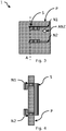
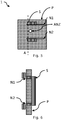
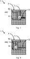
- FIG. 1-4 is a first embodiment and in Figures 5-8 a second embodiment of a space-saving separation device 1 according to the invention is shown.
- a space-saving separation device 1 It is common to all embodiments of a space-saving separation device 1 according to the invention that it has a carrier P with an electrical component B.
- the electrical component B can in particular have an overvoltage protection element.
- the carrier P can e.g. be a circuit board or have a circuit board material. As a rule, the carrier will be essentially rigid.
- the purpose of the space-saving separation device 1 according to the invention is to separate the electrical component B in the event of inadmissible heating.
- the carrier P has at least two guide grooves N1, N2. These guide grooves N1, N2 can e.g. be introduced into the carrier P by means of punching, laser processing, milling, etc.
- the electrical component B is fastened on the carrier P with a thermally softenable fixation.
- the thermally softenable fixation can have a solder and / or an adhesive. If the heat-softenable fixation has a solder, then, for example, the electrical component B can have connections for surface mounting for conductor tracks of the carrier P.
- the electrical component B and with it also the solder heat to temperatures that are above the softening point of the solder but below the softening point of the adhesive. In this case, the solder still establishes the electrical connection because it remains in contact due to the surface forces.
- an energy accumulator D is arranged relative to the electrical component B, which - when the thermally softenable fixation softens - shifts the electrical component B essentially parallel to the carrier P and thereby separates the electrical component B.
- the energy store D can e.g. a spring (as shown) or a spring clip, a compressed elastomer, etc.
- the energy accumulator D exerts a continuous force after assembly, which in the event that the fixation softens leads to a movement.
- a displacement by pressure is shown in the figures, the invention is not limited to this.
- All embodiments of an installation space-optimized separation device 1 according to the invention also have in common that they have a mechanically displaceable display means S, the mechanically displaceable display means S indicating that the electrical component B to be monitored has been disconnected, the mechanically displaceable display means S together with the separating electrical component is moved.
- the mechanically displaceable display means S enclose the electrical component B laterally, ie in a plane parallel to the carrier P, or, as in Figures 7 and 8 shown, partially bordering.
- the Energy store D can be moved indirectly via the mechanically movable display means S, moves in Figures 7 and 8 the energy store D via the electrical component B the mechanically displaceable display means S.
- the mechanically displaceable display means S covers the electrical component in a hood-like manner.
- the mechanically displaceable display means S has further properties, such as, for example, extinguishing properties, for example in that it has hard gas material. Furthermore, it can also be provided that the design of the mechanical display means S, when triggered, constricts and / or extends a possible arc path. In addition, it can be provided that the mechanical display means S also functions as a heat sink for the electrical component B.
- the mechanically displaceable display means S is held and guided in the at least two guide grooves N1, N2.
- the arrangement of the first embodiment differs from the second embodiment in that the holder is achieved in that the in the embodiment of Figure 4 an inward wrap is displayed while in Figure 6 an outward wrap is indicated. It should be noted that a wrap around in the same direction is also possible.
- Such encirclements can be provided as molded parts which are guided through the guide grooves N1, N2 in a resilient and / or pressing manner during the assembly of the mechanically displaceable display means S and which expand again after the implementation. That the mechanically displaceable display means S can e.g. be snapped on. However, it is also possible to form encapsulations on the mechanically displaceable display means S by inserting them into the guide grooves N1, N2.
- a disconnecting device 1 can now be mounted on the carrier P after the electrical component B has been installed, without the risk that Elements can slip.
- the energy store D can be used.
- the electrical component B heats up, the electrical component B is released after the energy storage device D has been released, e.g. in the event of an error, moved along the surface of the carrier P.
- the travel path of the electrical component B can be used to simultaneously implement a mechanical display.
- the invention makes it possible to produce a simple and safe and inexpensive separation device which takes up little installation space and can also signal a separation.
- the mechanically displaceable display means S it is also possible for the mechanically displaceable display means S to have a device for fixing the mechanically displaceable display means S in an initial position.
- This fixation is preferably provided by the previously fixed electrical component B. That the manufacturing process can be further simplified and the security against tripping increased.
- the disconnection device 1 for a disconnected electrical component B it is also possible for the disconnection device 1 for a disconnected electrical component B to be monitored to have a device for fixing in a disconnected state.
- a hood-like mechanically displaceable display means S and the carrier P can fix the separated electrical component B.
- the arrangement described above makes it possible To implement devices with electrical components B and a separation device according to the invention, which do not have a supporting housing wall due to the design. If the mechanically displaceable display means S encompasses the separated electrical component B only laterally, a housing section parallel to the carrier P can prevent the electrical component B from becoming vaguely normal to the carrier P.
- the mechanically displaceable display means S can provide a color change and / or a change in transmission.
- an opening ANZ can be provided in a housing and / or in the carrier P, in which an color change field is shifted with / on the mechanically displaceable display means S when the electrical component B is separated. That e.g. a color change from green to red indicates that the separation has taken place.
- an embodiment is shown in which an opening ANZ in the carrier P is covered by the mechanical display means S ( Fig. 2 ) can be.
- an embodiment is shown in which an opening ANZ in the carrier P is opened by the mechanical display means S ( Fig. 8 ) can be.
- the separating device 1 it is also possible for the separating device 1 to have devices for mounting on a mounting rail.
- a separating device 1 according to the invention can also be installed in switch cabinets by means of suitable housings with the corresponding devices.
- guide grooves N1, N2 are shown in the figures, the invention is not limited to this. Rather, there are no limits for the person skilled in the art. However, essentially straight guide grooves N1, N2 allow particularly simple movement.
Landscapes
- Chemical & Material Sciences (AREA)
- Engineering & Computer Science (AREA)
- Combustion & Propulsion (AREA)
- Fuses (AREA)
- Cooling Or The Like Of Electrical Apparatus (AREA)
Priority Applications (1)
| Application Number | Priority Date | Filing Date | Title |
|---|---|---|---|
| SI201930017T SI3605574T1 (sl) | 2018-07-30 | 2019-07-30 | Ločevalna naprava z optimiziranim instalacijskim območjem |
Applications Claiming Priority (1)
| Application Number | Priority Date | Filing Date | Title |
|---|---|---|---|
| DE102018212690.9A DE102018212690A1 (de) | 2018-07-30 | 2018-07-30 | Bauraumoptimierte Abtrennvorrichtung |
Publications (2)
| Publication Number | Publication Date |
|---|---|
| EP3605574A1 true EP3605574A1 (fr) | 2020-02-05 |
| EP3605574B1 EP3605574B1 (fr) | 2020-11-25 |
Family
ID=67438287
Family Applications (1)
| Application Number | Title | Priority Date | Filing Date |
|---|---|---|---|
| EP19188998.9A Active EP3605574B1 (fr) | 2018-07-30 | 2019-07-30 | Dispositif de séparation à encombrement réduit |
Country Status (4)
| Country | Link |
|---|---|
| EP (1) | EP3605574B1 (fr) |
| CN (1) | CN210156315U (fr) |
| DE (1) | DE102018212690A1 (fr) |
| SI (1) | SI3605574T1 (fr) |
Families Citing this family (1)
| Publication number | Priority date | Publication date | Assignee | Title |
|---|---|---|---|---|
| DE102023125692B3 (de) | 2023-09-21 | 2024-12-05 | Günther Spelsberg GmbH & Co. Kommanditgesellschaft | Elektrische Verbindungsvorrichtung mit Sicherungselement |
Citations (12)
| Publication number | Priority date | Publication date | Assignee | Title |
|---|---|---|---|---|
| DE9010246U1 (de) | 1990-07-06 | 1990-10-31 | CITEL 2CP S.A., Nederweert | Überspannungsschutzvorrichtung |
| DE4241311C2 (de) | 1992-12-08 | 1995-06-08 | Phoenix Contact Gmbh & Co | Temperaturschalter mit einem Bausteingehäuse |
| US5831507A (en) * | 1996-09-09 | 1998-11-03 | Toyo System Co., Ltd. | Dual-functional fuse unit that is responsive to electric current and ambient temperature |
| US6430019B1 (en) | 1998-06-08 | 2002-08-06 | Ferraz S.A. | Circuit protection device |
| DE69904274T2 (de) | 1998-09-15 | 2003-08-28 | Soule Materiel Electrique, Bagneres-De-Bigorre | Schutzvorrichtung für elektrischen Anlagen gegen Speisungsstörungen |
| DE102005040308A1 (de) | 2005-08-24 | 2007-03-01 | Wehrle Autoelektronik Gmbh | Thermosicherung, insbesondere für ein Leistungsmodul eines Kraftfahrzeugs, sowie Leistungsmodul mit einer derartigen Thermosicherung |
| DE102006042028B3 (de) * | 2006-07-19 | 2007-09-27 | Dehn + Söhne Gmbh + Co. Kg | Abtrennvorrichtung für insbesondere steckbare Überspannungsableiter |
| DE102008057166A1 (de) | 2008-11-13 | 2010-05-20 | Behr-Hella Thermocontrol Gmbh | Elektrische Schaltung mit Übertemperaturschutz |
| DE102009036578B3 (de) | 2009-08-07 | 2010-09-09 | Magna Electronics Europe Gmbh & Co.Kg | Thermosicherung, insbesondere für ein Leistungsmodul eines Kraftfahrzeugs, sowie Leisstungsmodul mit einer derartigen Thermosicherung |
| WO2011011985A1 (fr) * | 2009-07-27 | 2011-02-03 | 佛山市浦斯电子有限公司 | Limiteur de surtension à dispositif de protection thermique |
| DE102015213050A1 (de) * | 2015-07-13 | 2017-01-19 | Phoenix Contact Gmbh & Co. Kg | Varistor mit einer Abtrennvorrichtung |
| DE202016102862U1 (de) | 2016-05-31 | 2017-09-03 | Phoenix Contact Gmbh & Co. Kg | Bauraumoptimierte Abtrennvorrichtung |
Family Cites Families (2)
| Publication number | Priority date | Publication date | Assignee | Title |
|---|---|---|---|---|
| US9455106B2 (en) * | 2011-02-02 | 2016-09-27 | Littelfuse, Inc. | Three-function reflowable circuit protection device |
| DE102014008366B3 (de) * | 2014-06-04 | 2015-10-22 | Dehn + Söhne Gmbh + Co. Kg | Vorrichtung zum thermischen Auslösen oder Abtrennen eines Überspannungsschutzgerätes |
-
2018
- 2018-07-30 DE DE102018212690.9A patent/DE102018212690A1/de not_active Ceased
-
2019
- 2019-07-26 CN CN201921186194.3U patent/CN210156315U/zh active Active
- 2019-07-30 EP EP19188998.9A patent/EP3605574B1/fr active Active
- 2019-07-30 SI SI201930017T patent/SI3605574T1/sl unknown
Patent Citations (12)
| Publication number | Priority date | Publication date | Assignee | Title |
|---|---|---|---|---|
| DE9010246U1 (de) | 1990-07-06 | 1990-10-31 | CITEL 2CP S.A., Nederweert | Überspannungsschutzvorrichtung |
| DE4241311C2 (de) | 1992-12-08 | 1995-06-08 | Phoenix Contact Gmbh & Co | Temperaturschalter mit einem Bausteingehäuse |
| US5831507A (en) * | 1996-09-09 | 1998-11-03 | Toyo System Co., Ltd. | Dual-functional fuse unit that is responsive to electric current and ambient temperature |
| US6430019B1 (en) | 1998-06-08 | 2002-08-06 | Ferraz S.A. | Circuit protection device |
| DE69904274T2 (de) | 1998-09-15 | 2003-08-28 | Soule Materiel Electrique, Bagneres-De-Bigorre | Schutzvorrichtung für elektrischen Anlagen gegen Speisungsstörungen |
| DE102005040308A1 (de) | 2005-08-24 | 2007-03-01 | Wehrle Autoelektronik Gmbh | Thermosicherung, insbesondere für ein Leistungsmodul eines Kraftfahrzeugs, sowie Leistungsmodul mit einer derartigen Thermosicherung |
| DE102006042028B3 (de) * | 2006-07-19 | 2007-09-27 | Dehn + Söhne Gmbh + Co. Kg | Abtrennvorrichtung für insbesondere steckbare Überspannungsableiter |
| DE102008057166A1 (de) | 2008-11-13 | 2010-05-20 | Behr-Hella Thermocontrol Gmbh | Elektrische Schaltung mit Übertemperaturschutz |
| WO2011011985A1 (fr) * | 2009-07-27 | 2011-02-03 | 佛山市浦斯电子有限公司 | Limiteur de surtension à dispositif de protection thermique |
| DE102009036578B3 (de) | 2009-08-07 | 2010-09-09 | Magna Electronics Europe Gmbh & Co.Kg | Thermosicherung, insbesondere für ein Leistungsmodul eines Kraftfahrzeugs, sowie Leisstungsmodul mit einer derartigen Thermosicherung |
| DE102015213050A1 (de) * | 2015-07-13 | 2017-01-19 | Phoenix Contact Gmbh & Co. Kg | Varistor mit einer Abtrennvorrichtung |
| DE202016102862U1 (de) | 2016-05-31 | 2017-09-03 | Phoenix Contact Gmbh & Co. Kg | Bauraumoptimierte Abtrennvorrichtung |
Also Published As
| Publication number | Publication date |
|---|---|
| EP3605574B1 (fr) | 2020-11-25 |
| CN210156315U (zh) | 2020-03-17 |
| DE102018212690A1 (de) | 2020-01-30 |
| SI3605574T1 (sl) | 2021-07-30 |
Similar Documents
| Publication | Publication Date | Title |
|---|---|---|
| DE102014008366B3 (de) | Vorrichtung zum thermischen Auslösen oder Abtrennen eines Überspannungsschutzgerätes | |
| WO2013167253A1 (fr) | Borne de connexion électrique | |
| DE202010014431U1 (de) | Überspannungsschutzelement | |
| DE102011053414A1 (de) | Thermische Abtrennvorrichtung für Überspannungsschutzgeräte | |
| DE202014103262U1 (de) | Überspannungsschutzelement | |
| DE202010017932U1 (de) | Überspannungsschutzelement | |
| WO2002033721A1 (fr) | Protection contre les surcharges pour machines electriques | |
| DE102008029670A1 (de) | Überspannungsschutzelement | |
| EP3245661A1 (fr) | Composant de coupe-circuit à fusible | |
| EP3128624B1 (fr) | Systeme de parasurtenseurs | |
| EP3745432B1 (fr) | Agencement de protection contre les surcharges | |
| EP3605574B1 (fr) | Dispositif de séparation à encombrement réduit | |
| EP2280457A2 (fr) | Elément de protection contre les surtensions | |
| DE202016102520U1 (de) | Kostengünstige thermische Abtrennvorrichtung für eine elektrische Komponente | |
| DE202010014430U1 (de) | Überspannungsschutzelement und elektrisches Gerät | |
| DE102017218582B4 (de) | Bauraumbegrenztes Schutzmodul mit zumindest zwei Überspannungsschutzelementen in parallelen Stromzweigen | |
| DE102015014163A1 (de) | Vorrichtung zum thermischen Auslösen, Abtrennen und/oder Signalisieren des Zustandes eines Überspannungsschutzgerätes | |
| DE102017131154B4 (de) | Überspannungsschutzanordnung | |
| DE102007024622B4 (de) | Überspannungsschutzeinrichtung | |
| DE102017113852A1 (de) | Überspannungsschutzelement | |
| DE202016102862U1 (de) | Bauraumoptimierte Abtrennvorrichtung | |
| DE102013214194B4 (de) | Bauraumbegrenzte Überspannungsschutzvorrichtung und Verfahren zu dessen Herstellung | |
| DE202019103666U1 (de) | Überspannungsschutzelement und Überspannungsschutzgerät | |
| DE102018220149B3 (de) | Baugruppe mit einem elektrotechnischen Bauelement auf einem Träger | |
| DE102018129679A1 (de) | Überspannungsschutzvorrichtung mit thermischer Überlastschutzvorrichtung |
Legal Events
| Date | Code | Title | Description |
|---|---|---|---|
| PUAI | Public reference made under article 153(3) epc to a published international application that has entered the european phase |
Free format text: ORIGINAL CODE: 0009012 |
|
| STAA | Information on the status of an ep patent application or granted ep patent |
Free format text: STATUS: REQUEST FOR EXAMINATION WAS MADE |
|
| 17P | Request for examination filed |
Effective date: 20190730 |
|
| AK | Designated contracting states |
Kind code of ref document: A1 Designated state(s): AL AT BE BG CH CY CZ DE DK EE ES FI FR GB GR HR HU IE IS IT LI LT LU LV MC MK MT NL NO PL PT RO RS SE SI SK SM TR |
|
| AX | Request for extension of the european patent |
Extension state: BA ME |
|
| RBV | Designated contracting states (corrected) |
Designated state(s): AL AT BE BG CH CY CZ DE DK EE ES FI FR GB GR HR HU IE IS IT LI LT LU LV MC MK MT NL NO PL PT RO RS SE SI SK SM TR |
|
| RIC1 | Information provided on ipc code assigned before grant |
Ipc: H01H 37/76 20060101ALI20200709BHEP Ipc: H01H 9/18 20060101AFI20200709BHEP |
|
| GRAP | Despatch of communication of intention to grant a patent |
Free format text: ORIGINAL CODE: EPIDOSNIGR1 |
|
| STAA | Information on the status of an ep patent application or granted ep patent |
Free format text: STATUS: GRANT OF PATENT IS INTENDED |
|
| INTG | Intention to grant announced |
Effective date: 20200914 |
|
| GRAS | Grant fee paid |
Free format text: ORIGINAL CODE: EPIDOSNIGR3 |
|
| GRAA | (expected) grant |
Free format text: ORIGINAL CODE: 0009210 |
|
| STAA | Information on the status of an ep patent application or granted ep patent |
Free format text: STATUS: THE PATENT HAS BEEN GRANTED |
|
| AK | Designated contracting states |
Kind code of ref document: B1 Designated state(s): AL AT BE BG CH CY CZ DE DK EE ES FI FR GB GR HR HU IE IS IT LI LT LU LV MC MK MT NL NO PL PT RO RS SE SI SK SM TR |
|
| REG | Reference to a national code |
Ref country code: GB Ref legal event code: FG4D Free format text: NOT ENGLISH |
|
| REG | Reference to a national code |
Ref country code: CH Ref legal event code: EP |
|
| REG | Reference to a national code |
Ref country code: AT Ref legal event code: REF Ref document number: 1339242 Country of ref document: AT Kind code of ref document: T Effective date: 20201215 |
|
| REG | Reference to a national code |
Ref country code: DE Ref legal event code: R096 Ref document number: 502019000451 Country of ref document: DE |
|
| REG | Reference to a national code |
Ref country code: IE Ref legal event code: FG4D Free format text: LANGUAGE OF EP DOCUMENT: GERMAN |
|
| REG | Reference to a national code |
Ref country code: NL Ref legal event code: MP Effective date: 20201125 |
|
| PG25 | Lapsed in a contracting state [announced via postgrant information from national office to epo] |
Ref country code: GR Free format text: LAPSE BECAUSE OF FAILURE TO SUBMIT A TRANSLATION OF THE DESCRIPTION OR TO PAY THE FEE WITHIN THE PRESCRIBED TIME-LIMIT Effective date: 20210226 Ref country code: NO Free format text: LAPSE BECAUSE OF FAILURE TO SUBMIT A TRANSLATION OF THE DESCRIPTION OR TO PAY THE FEE WITHIN THE PRESCRIBED TIME-LIMIT Effective date: 20210225 Ref country code: FI Free format text: LAPSE BECAUSE OF FAILURE TO SUBMIT A TRANSLATION OF THE DESCRIPTION OR TO PAY THE FEE WITHIN THE PRESCRIBED TIME-LIMIT Effective date: 20201125 Ref country code: PT Free format text: LAPSE BECAUSE OF FAILURE TO SUBMIT A TRANSLATION OF THE DESCRIPTION OR TO PAY THE FEE WITHIN THE PRESCRIBED TIME-LIMIT Effective date: 20210325 Ref country code: RS Free format text: LAPSE BECAUSE OF FAILURE TO SUBMIT A TRANSLATION OF THE DESCRIPTION OR TO PAY THE FEE WITHIN THE PRESCRIBED TIME-LIMIT Effective date: 20201125 |
|
| PG25 | Lapsed in a contracting state [announced via postgrant information from national office to epo] |
Ref country code: SE Free format text: LAPSE BECAUSE OF FAILURE TO SUBMIT A TRANSLATION OF THE DESCRIPTION OR TO PAY THE FEE WITHIN THE PRESCRIBED TIME-LIMIT Effective date: 20201125 Ref country code: LV Free format text: LAPSE BECAUSE OF FAILURE TO SUBMIT A TRANSLATION OF THE DESCRIPTION OR TO PAY THE FEE WITHIN THE PRESCRIBED TIME-LIMIT Effective date: 20201125 Ref country code: IS Free format text: LAPSE BECAUSE OF FAILURE TO SUBMIT A TRANSLATION OF THE DESCRIPTION OR TO PAY THE FEE WITHIN THE PRESCRIBED TIME-LIMIT Effective date: 20210325 Ref country code: PL Free format text: LAPSE BECAUSE OF FAILURE TO SUBMIT A TRANSLATION OF THE DESCRIPTION OR TO PAY THE FEE WITHIN THE PRESCRIBED TIME-LIMIT Effective date: 20201125 Ref country code: BG Free format text: LAPSE BECAUSE OF FAILURE TO SUBMIT A TRANSLATION OF THE DESCRIPTION OR TO PAY THE FEE WITHIN THE PRESCRIBED TIME-LIMIT Effective date: 20210225 |
|
| REG | Reference to a national code |
Ref country code: LT Ref legal event code: MG9D |
|
| PG25 | Lapsed in a contracting state [announced via postgrant information from national office to epo] |
Ref country code: HR Free format text: LAPSE BECAUSE OF FAILURE TO SUBMIT A TRANSLATION OF THE DESCRIPTION OR TO PAY THE FEE WITHIN THE PRESCRIBED TIME-LIMIT Effective date: 20201125 |
|
| PG25 | Lapsed in a contracting state [announced via postgrant information from national office to epo] |
Ref country code: RO Free format text: LAPSE BECAUSE OF FAILURE TO SUBMIT A TRANSLATION OF THE DESCRIPTION OR TO PAY THE FEE WITHIN THE PRESCRIBED TIME-LIMIT Effective date: 20201125 Ref country code: LT Free format text: LAPSE BECAUSE OF FAILURE TO SUBMIT A TRANSLATION OF THE DESCRIPTION OR TO PAY THE FEE WITHIN THE PRESCRIBED TIME-LIMIT Effective date: 20201125 Ref country code: CZ Free format text: LAPSE BECAUSE OF FAILURE TO SUBMIT A TRANSLATION OF THE DESCRIPTION OR TO PAY THE FEE WITHIN THE PRESCRIBED TIME-LIMIT Effective date: 20201125 Ref country code: EE Free format text: LAPSE BECAUSE OF FAILURE TO SUBMIT A TRANSLATION OF THE DESCRIPTION OR TO PAY THE FEE WITHIN THE PRESCRIBED TIME-LIMIT Effective date: 20201125 Ref country code: SK Free format text: LAPSE BECAUSE OF FAILURE TO SUBMIT A TRANSLATION OF THE DESCRIPTION OR TO PAY THE FEE WITHIN THE PRESCRIBED TIME-LIMIT Effective date: 20201125 Ref country code: SM Free format text: LAPSE BECAUSE OF FAILURE TO SUBMIT A TRANSLATION OF THE DESCRIPTION OR TO PAY THE FEE WITHIN THE PRESCRIBED TIME-LIMIT Effective date: 20201125 |
|
| REG | Reference to a national code |
Ref country code: DE Ref legal event code: R097 Ref document number: 502019000451 Country of ref document: DE |
|
| PG25 | Lapsed in a contracting state [announced via postgrant information from national office to epo] |
Ref country code: DK Free format text: LAPSE BECAUSE OF FAILURE TO SUBMIT A TRANSLATION OF THE DESCRIPTION OR TO PAY THE FEE WITHIN THE PRESCRIBED TIME-LIMIT Effective date: 20201125 |
|
| PLBE | No opposition filed within time limit |
Free format text: ORIGINAL CODE: 0009261 |
|
| STAA | Information on the status of an ep patent application or granted ep patent |
Free format text: STATUS: NO OPPOSITION FILED WITHIN TIME LIMIT |
|
| PG25 | Lapsed in a contracting state [announced via postgrant information from national office to epo] |
Ref country code: IT Free format text: LAPSE BECAUSE OF FAILURE TO SUBMIT A TRANSLATION OF THE DESCRIPTION OR TO PAY THE FEE WITHIN THE PRESCRIBED TIME-LIMIT Effective date: 20201125 Ref country code: NL Free format text: LAPSE BECAUSE OF FAILURE TO SUBMIT A TRANSLATION OF THE DESCRIPTION OR TO PAY THE FEE WITHIN THE PRESCRIBED TIME-LIMIT Effective date: 20201125 Ref country code: AL Free format text: LAPSE BECAUSE OF FAILURE TO SUBMIT A TRANSLATION OF THE DESCRIPTION OR TO PAY THE FEE WITHIN THE PRESCRIBED TIME-LIMIT Effective date: 20201125 |
|
| 26N | No opposition filed |
Effective date: 20210826 |
|
| PG25 | Lapsed in a contracting state [announced via postgrant information from national office to epo] |
Ref country code: ES Free format text: LAPSE BECAUSE OF FAILURE TO SUBMIT A TRANSLATION OF THE DESCRIPTION OR TO PAY THE FEE WITHIN THE PRESCRIBED TIME-LIMIT Effective date: 20201125 |
|
| PG25 | Lapsed in a contracting state [announced via postgrant information from national office to epo] |
Ref country code: MC Free format text: LAPSE BECAUSE OF FAILURE TO SUBMIT A TRANSLATION OF THE DESCRIPTION OR TO PAY THE FEE WITHIN THE PRESCRIBED TIME-LIMIT Effective date: 20201125 |
|
| REG | Reference to a national code |
Ref country code: BE Ref legal event code: MM Effective date: 20210731 |
|
| PG25 | Lapsed in a contracting state [announced via postgrant information from national office to epo] |
Ref country code: LU Free format text: LAPSE BECAUSE OF NON-PAYMENT OF DUE FEES Effective date: 20210730 |
|
| PG25 | Lapsed in a contracting state [announced via postgrant information from national office to epo] |
Ref country code: IE Free format text: LAPSE BECAUSE OF NON-PAYMENT OF DUE FEES Effective date: 20210730 Ref country code: BE Free format text: LAPSE BECAUSE OF NON-PAYMENT OF DUE FEES Effective date: 20210731 |
|
| REG | Reference to a national code |
Ref country code: CH Ref legal event code: PL |
|
| PG25 | Lapsed in a contracting state [announced via postgrant information from national office to epo] |
Ref country code: LI Free format text: LAPSE BECAUSE OF NON-PAYMENT OF DUE FEES Effective date: 20220731 Ref country code: CH Free format text: LAPSE BECAUSE OF NON-PAYMENT OF DUE FEES Effective date: 20220731 |
|
| P01 | Opt-out of the competence of the unified patent court (upc) registered |
Effective date: 20230424 |
|
| PG25 | Lapsed in a contracting state [announced via postgrant information from national office to epo] |
Ref country code: CY Free format text: LAPSE BECAUSE OF FAILURE TO SUBMIT A TRANSLATION OF THE DESCRIPTION OR TO PAY THE FEE WITHIN THE PRESCRIBED TIME-LIMIT Effective date: 20201125 |
|
| PG25 | Lapsed in a contracting state [announced via postgrant information from national office to epo] |
Ref country code: HU Free format text: LAPSE BECAUSE OF FAILURE TO SUBMIT A TRANSLATION OF THE DESCRIPTION OR TO PAY THE FEE WITHIN THE PRESCRIBED TIME-LIMIT; INVALID AB INITIO Effective date: 20190730 |
|
| GBPC | Gb: european patent ceased through non-payment of renewal fee |
Effective date: 20230730 |
|
| PG25 | Lapsed in a contracting state [announced via postgrant information from national office to epo] |
Ref country code: MK Free format text: LAPSE BECAUSE OF FAILURE TO SUBMIT A TRANSLATION OF THE DESCRIPTION OR TO PAY THE FEE WITHIN THE PRESCRIBED TIME-LIMIT Effective date: 20201125 Ref country code: GB Free format text: LAPSE BECAUSE OF NON-PAYMENT OF DUE FEES Effective date: 20230730 |
|
| PG25 | Lapsed in a contracting state [announced via postgrant information from national office to epo] |
Ref country code: TR Free format text: LAPSE BECAUSE OF FAILURE TO SUBMIT A TRANSLATION OF THE DESCRIPTION OR TO PAY THE FEE WITHIN THE PRESCRIBED TIME-LIMIT Effective date: 20201125 |
|
| PG25 | Lapsed in a contracting state [announced via postgrant information from national office to epo] |
Ref country code: MT Free format text: LAPSE BECAUSE OF FAILURE TO SUBMIT A TRANSLATION OF THE DESCRIPTION OR TO PAY THE FEE WITHIN THE PRESCRIBED TIME-LIMIT Effective date: 20201125 |
|
| PGFP | Annual fee paid to national office [announced via postgrant information from national office to epo] |
Ref country code: FR Payment date: 20240725 Year of fee payment: 6 |
|
| PGFP | Annual fee paid to national office [announced via postgrant information from national office to epo] |
Ref country code: SI Payment date: 20250716 Year of fee payment: 7 |
|
| REG | Reference to a national code |
Ref country code: AT Ref legal event code: MM01 Ref document number: 1339242 Country of ref document: AT Kind code of ref document: T Effective date: 20240730 |
|
| PGFP | Annual fee paid to national office [announced via postgrant information from national office to epo] |
Ref country code: DE Payment date: 20250926 Year of fee payment: 7 |
|
| PG25 | Lapsed in a contracting state [announced via postgrant information from national office to epo] |
Ref country code: AT Free format text: LAPSE BECAUSE OF NON-PAYMENT OF DUE FEES Effective date: 20240730 |
|
| PGFP | Annual fee paid to national office [announced via postgrant information from national office to epo] |
Ref country code: AT Payment date: 20260410 Year of fee payment: 5 |
|
| PG25 | Lapsed in a contracting state [announced via postgrant information from national office to epo] |
Ref country code: FR Free format text: LAPSE BECAUSE OF NON-PAYMENT OF DUE FEES Effective date: 20250731 |