EP3606794B1 - Arrangement de lavage de roue et procédé de nettoyage d'une roue ainsi qu'installation de lavage pour véhicules - Google Patents
Arrangement de lavage de roue et procédé de nettoyage d'une roue ainsi qu'installation de lavage pour véhicules Download PDFInfo
- Publication number
- EP3606794B1 EP3606794B1 EP17716851.5A EP17716851A EP3606794B1 EP 3606794 B1 EP3606794 B1 EP 3606794B1 EP 17716851 A EP17716851 A EP 17716851A EP 3606794 B1 EP3606794 B1 EP 3606794B1
- Authority
- EP
- European Patent Office
- Prior art keywords
- wheel
- brush
- joint
- brush device
- trajectory
- Prior art date
- Legal status (The legal status is an assumption and is not a legal conclusion. Google has not performed a legal analysis and makes no representation as to the accuracy of the status listed.)
- Active
Links
Images


Classifications
-
- B—PERFORMING OPERATIONS; TRANSPORTING
- B60—VEHICLES IN GENERAL
- B60S—SERVICING, CLEANING, REPAIRING, SUPPORTING, LIFTING, OR MANOEUVRING OF VEHICLES, NOT OTHERWISE PROVIDED FOR
- B60S3/00—Vehicle cleaning apparatus not integral with vehicles
- B60S3/04—Vehicle cleaning apparatus not integral with vehicles for exteriors of land vehicles
- B60S3/042—Wheel cleaning devices
-
- B—PERFORMING OPERATIONS; TRANSPORTING
- B60—VEHICLES IN GENERAL
- B60S—SERVICING, CLEANING, REPAIRING, SUPPORTING, LIFTING, OR MANOEUVRING OF VEHICLES, NOT OTHERWISE PROVIDED FOR
- B60S3/00—Vehicle cleaning apparatus not integral with vehicles
- B60S3/04—Vehicle cleaning apparatus not integral with vehicles for exteriors of land vehicles
- B60S3/06—Vehicle cleaning apparatus not integral with vehicles for exteriors of land vehicles with rotary bodies contacting the vehicle
Definitions
- the invention relates to a wheel washing device for cleaning a wheel of a motor vehicle, comprising a brush device which comprises or forms at least one brush that can be placed on the wheel, a drive device for driving the at least one brush in rotation, and a feed device with which the brush device is moved from a rest position away from the wheel at least one position of use close to the wheel can be transferred, the brush device being able to be lowered by means of the feed device when moving in the direction of the wheel.
- the present invention also relates to a method for cleaning a wheel.
- the present invention further relates to a vehicle washing system, comprising at least one wheel washing device for cleaning a wheel.
- vehicle washing system can be a portal washing system that moves relative to a stationary vehicle.
- vehicle washing system can be a washing line in which the vehicle to be cleaned is moved by means of a conveyor device.
- the brush device can be moved from a rest position remote from the wheel by means of the feed device in the direction of the wheel.
- cleaning elements of the at least one brush in particular cleaning bristles, can contact the wheel.
- the wheel is cleaned, in particular in the area of the rim.
- the brush device can then be transferred again from the position of use to the rest position by means of the feed device.
- motor vehicles usually have wheels of larger diameter, the wider the motor vehicles are. Accordingly, small cars are narrow and have rather small-diameter wheels. Compact or mid-range vehicles are wider and have larger-diameter wheels than small cars. Upper-class vehicles, especially large SUVs, are even wider and include wheels with an even larger diameter. For this reason, it is known to lower the brush device by means of the feed device when moving in the direction of the wheel. For example, the brush device can be lowered further, the narrower the motor vehicle is and the smaller the diameter of its wheels. Conversely, the brush device is lowered less if it is a motor vehicle with wheels of rather larger diameter. It goes without saying that correct positioning of the motor vehicle relative to the wheel washing device is assumed in the present case, in particular if the wheels of the motor vehicle are acted on from both sides by two wheel washing devices at the same time.
- a wheel washing device for cleaning a wheel in which the brush device is lowered in the direction of the wheel on an inclined plane in relation to a horizontal installation surface for the motor vehicle DE 1 655 989 described.
- the DE 20 2008 012 139 U1 also describes a wheel washing device for cleaning a wheel, in which the brush device is moved in an inclined plane and is lowered obliquely in the direction of the wheel.
- the U.S. 3,758,906 describes a wheel washing device for cleaning a wheel with a brush device that can be lowered during the feed movement.
- the brush device performs a pendulum movement by means of a joint parallelogram, so that the brush device is lowered along a convex trajectory in the direction of the wheel.
- FIG EP 2 332 793 A1 A wheel washing device with a brush device that can be moved translationally in three spatial directions is shown in FIG EP 2 332 793 A1 described.
- a brush device with a plurality of brushes is for example in the WO 2012/110094 A1 described.
- Position and orientation information such as "above”, “below” relate in the present case to an intended use of the wheel washing device for cleaning a wheel, which is used with a motor vehicle positioned on a set-up surface.
- the installation surface is viewed as being oriented horizontally or essentially horizontally.
- the brush device is moved by means of the feed device transversely to a longitudinal direction of the motor vehicle, i.e. the motor vehicle is preferably oriented relative to the wheel washing device in such a way that the longitudinal direction of the motor vehicle is oriented transversely and in particular perpendicular to a plane in which the feed movement of the brush device takes place.
- the object of the present invention is to provide a wheel washing device, a method for cleaning a wheel of a motor vehicle and a vehicle washing system with which a better cleaning result can be achieved for the motor vehicles to be cleaned.
- a wheel washing device for cleaning a wheel of a motor vehicle, comprising a brush device which comprises or forms at least one brush that can be placed on the wheel, a drive device for driving the at least one brush in rotation and a feed device with which the brush device is driven by a
- the rest position away from the wheel can be transferred into at least one use position close to the wheel, wherein the brush device can be lowered by means of the feed device during an infeed movement in the direction of the wheel, the brush device by means of the feed device when moving from the rest position into the at least one use position along at least one
- the trajectory having the turning point is movable and this trajectory passes through during the infeed movement.
- the infeed device is designed such that the brush device runs through a trajectory during the infeed movement which has at least one turning point. At the turning point the curvature of the trajectory changes.
- the infeed movement of the brush device therefore takes place differently than in the publications mentioned at the beginning DE 1 655 989 and DE 20 2008 012 139 U1 , not along a continuously inclined, rectilinear movement of the brush device.
- the brush device changes the direction of movement at least once at at least one turning point of the trajectory, although this is different in comparison to the one mentioned at the beginning U.S. 3,758,906 changes the curvature of the trajectory at least once.
- the trajectory is initially curved in the direction of the mounting surface for the motor vehicle, and from a turning point the trajectory changes in such a way that the trajectory is curved away from the mounting surface.
- the movement of the brush device along the trajectory with at least one turning point provides the best match with the circumstances if the diameter of the wheels in relation to the width of the vehicles is considered in the vast majority of motor vehicles. This shows, for example, that the diameter does not increase proportionally to the width. It is true that the wider the motor vehicle, the larger the wheels, the ratio of the diameter to the width initially increasing. However, the ratio of the diameter to the width decreases again as the width of the motor vehicle increases.
- the brush device depending on the width of the motor vehicle to be cleaned, generally only follows a section of the trajectory is moved. Under certain circumstances, with a relatively wide vehicle, a movement starting from the rest position does not even take place up to the at least one turning point of the trajectory.
- the brush device can be moved along a trajectory that has precisely one turning point.
- the at least one turning point is arranged in the middle or essentially in the middle between the rest position and a use position of the brush direction that is maximally extended with respect to the rest position.
- the brush device can be moved into a plurality of positions of use, the respective position of use being determined by the width of the motor vehicle and the position of the wheel dependent thereon.
- the brushes with cleaning elements rest on the wheel.
- the brush device can therefore be transferred from the rest position to a position of use that is extended to the maximum with respect to this position.
- the at least one turning point and in particular exactly one turning point is advantageously in the middle or essentially in the middle between the maximally extended use position and the rest position.
- the brush device starting from the rest position, can be moved along an arcuate trajectory up to the at least one turning point.
- the brush device is advantageously moved along an arc with a concave trajectory that is curved in the direction of the installation surface.
- the brush device can be moved along an arcuate trajectory starting from at least one turning point up to a position of use of the brush device that is maximally extended with respect to the rest position.
- the brush device is advantageously moved along an arc with a convex trajectory that is curved away from the installation surface.
- the brush device can be moved along a path curve which is essentially point-symmetrical with respect to the at least one turning point.
- the brush device can be moved along an approximately cosine-shaped trajectory starting from the rest position.
- the trajectory can initially be curved in an arc in the direction of the installation surface. At the turning point, the curvature of the trajectory changes in such a way that it is curved away from the installation surface in an arc.
- the brush device can be moved parallel to or substantially parallel to a mounting surface for the motor vehicle when moving from the rest position.
- the brush device can accordingly initially be moved parallel or essentially parallel to the installation surface. This can in particular correspond to a horizontal or essentially horizontal movement.
- the brush device can be moved parallel or essentially parallel (in particular horizontally or essentially horizontally) to a standing surface for the motor vehicle when it is moved into a position of use that is maximally extended with respect to the rest position.
- the brush device is positioned perpendicularly or essentially perpendicularly to a mounting surface for the motor vehicle aligned plane is movable. This is in particular a vertical or essentially vertical plane.
- the infeed device advantageously comprises a holding device to which the brush device is fixed, and an adjusting device coupled to the holding device for transferring the brush device from the rest position to the at least one position of use.
- the adjusting device can act on the holding device in order to move and / or deform it with the brush device held thereon. As a result, the brush device can be moved in both cases.
- the adjusting device can act on the holding device with both effective ends. It is also conceivable that the adjusting device engages with a first effective end on the holding device and with a second effective end on a support device via which the wheel washing device according to the invention stands on the installation surface for the motor vehicle.
- the carrying device can be, for example, a washing portal of a vehicle washing system that includes the wheel washing device.
- the adjustment device can be designed, for example, electrically, mechanically, pneumatically and / or hydraulically.
- a control device can be provided for controlling the adjustment device.
- the adjusting device can comprise or form at least one piston-cylinder unit.
- the holding device can be moved or deformed and the brush device can thereby be advanced.
- the infeed device comprises a guide device for guiding the movement of the brush device.
- a reliable movement of the brush device can be ensured during the infeed along the intended trajectory.
- the guide device can comprise at least one guide slot in which at least one guide member of the holding device engages and the course of which defines the trajectory.
- the holding device can comprise one or more guide members which engage in the guide slot. If the holding device is moved by means of the adjusting device, the guide link serves to guide the holding device, as a result of which the brush device is moved along the trajectory.
- a plurality of guide slots can be provided, the holding device engaging with at least one guide member in a respective guide slot. Alternatively or in addition, it is conceivable that the holding device engages with two or more guide members in a guide slot.
- An advantageous embodiment of the wheel washing device according to the invention provides that two guide slots are provided which are arranged at a distance from one another and between which the holding device is arranged.
- the holding device can thus be supported on both sides in the guide slots and can thus be reliably guided. This ensures, in particular, a tilt-free movement or deformation of the holding device.
- the holding device comprises or forms the guide device.
- the guide device comprises at least one joint arrangement with joint members which can be pivoted relative to one another and to which the brush device is fixed directly or indirectly via a holding part of the holding device.
- the brush device can be fixed to the joint members directly or indirectly by means of a holding part of the holding device.
- the joint arrangement can be fixed on a side opposite the brush device directly or indirectly, for example by means of a holding part of the holding device, on a support device for the wheel washing device.
- the adjusting device can at least engage a joint member and thereby pivot the joint members relative to one another in this way in order to transfer the brush device from the rest position into the at least one position of use.
- a wheel washing device of the type mentioned at the outset which comprises a holding device and an adjusting device
- the guide device comprises at least one joint arrangement with joint members which can be pivoted relative to one another and on which the brush device is fixed directly or indirectly via a holding part of the holding device.
- Such a wheel washing device for cleaning a wheel can represent an independent invention.
- the brush device could move in a straight line, in which the brush device can be lowered in the direction of the wheel during the feed movement.
- the joint arrangement can advantageously comprise or form at least one scissors joint, the legs of which are the joint members.
- a holding device and at least one adjusting device are provided, as explained above.
- Legs of the scissor joint (s) could be hinged to holding parts of the holding device, the brush device being fixed on one holding part and the other holding part being fixed on the carrying device.
- Joint members of the joint arrangement that are pivotably connected to one another advantageously define joints with respective joint axes running parallel to one another.
- the joint axes are advantageously aligned parallel or essentially parallel to a mounting surface for the motor vehicle.
- the joint arrangement comprises or forms at least one scissors joint, the legs of which are the joint members.
- the brush device can be structurally simple and functionally reliable via the scissors joint be transferred from the retracted rest position to the at least one extended use position. In the rest position, the wheel washing device takes up relatively little space due to the scissor joint.
- the joint arrangement comprises a joint member which is connected in an articulated manner to one of the legs of the scissors joint and to the brush device or the holding part on which the brush device is fixed.
- the joint member is accordingly articulated on one of the legs and on the brush device or on the holding part.
- the joint member can ensure that the brush device is not moved in a straight line by means of the scissor joint, but in an arc shape.
- the joint arrangement comprises a joint member which is articulated to one of the legs and to a holding part of the holding device, via which holding part the holding device is fixed to a support device for setting up the wheel washing device on a set-up surface for the motor vehicle .
- the joint member is articulated on the leg of the scissors joint and on the holding part. This ensures that the brush device is not moved in a straight line when moving by means of the scissor joint, but in an arc shape.
- the support device can be, for example, a washing portal or a part thereof.
- the support device can be stationary or can be moved relative to the motor vehicle.
- two joint arrangements which are arranged at a distance from one another and between which the adjustment device and / or the drive device for the brush device is arranged.
- Two joint arrangements enable a more robust construction of the wheel washing device and a more reliable delivery of the brush device.
- the installation space between the joint arrangements is advantageously used for the adjustment device and / or the drive device in order to achieve a compact design.
- joint arrangements are advantageously designed to be functionally identical, joint members of the joint arrangements that correspond to one another being connected to one another by a connecting member.
- the hinge assemblies can thereby be given a stiff, robust construction.
- Joint members of the joint arrangements including the connecting member have, for example, a bow-shaped, U-shaped shape.
- the joint arrangement also enables a relatively light construction of the wheel washing device.
- the adjustment device is coupled directly or indirectly to at least one joint member of the at least one joint arrangement.
- the adjusting device for example the piston-cylinder unit, can act on a joint member for deforming the joint arrangement.
- the adjusting device acts directly on a joint member.
- a coupling member is provided for coupling to the joint member.
- a bow-shaped coupling member is provided which is articulated to joint members of the two joint arrangements. If, as mentioned above, there are two joint arrangements, the adjusting device advantageously acts on both joint arrangements via the bow-shaped coupling member. Separate adjustment devices can thereby be saved will. At the same time, a reliable function of the delivery device is ensured.
- the infeed device advantageously comprises at least one restoring element which is effective against the action of the adjusting device and which acts to transfer the brush device in the at least one position of use into the rest position or at least supports this transfer.
- the at least one restoring element in the form of a spring element acts on the legs of the at least one scissors joint.
- the at least one restoring element is advantageously designed as a spring element, for example as a helical spring.
- the at least one restoring element is arranged between the joint arrangements. As a result, a compact design of the wheel washing device can be achieved.
- the at least one restoring element advantageously pretensions the joint members of the at least one joint arrangement relative to one another in the direction of the rest position of the brush device.
- the adjusting device has two drive units for moving the holding device in two directions oriented at an angle to one another, the movement of the brush device along the trajectory being controllable by controlling the drive units.
- the two drive units which can be controlled by a common control device, for example, the brush device can be moved along the trajectory in a targeted manner. It is advantageously possible, if necessary, to modify the shape of the trajectory by means of appropriate control.
- the two directions are advantageously aligned perpendicular or substantially perpendicular to one another.
- the directions are aligned parallel and perpendicular to a mounting surface for the motor vehicle, in particular horizontally and vertically.
- the drive device is advantageously fixed on the holding device.
- the holding device is fixed on the aforementioned holding part of the holding device on which the brush device is fixed.
- the brush device and the drive device are preferably arranged on opposite sides of the holding part.
- the brush device can have a distribution device for a cleaning liquid.
- a distribution device for a cleaning liquid For example, at least one nozzle is provided for spraying a cleaning liquid, in particular water. The cleaning effect of the wheel washing device can thereby be increased.
- a supply line for cleaning liquid is advantageously held on the holding device.
- the supply line is connected, for example, to the brush device in order to apply the cleaning liquid to the distribution device.
- a vehicle washing system according to the invention comprises at least one wheel washing device for cleaning a wheel of the type mentioned above.
- the vehicle wash system can be a gantry wash system or a car wash.
- An inventive method for cleaning a wheel of a motor vehicle which solves the problem mentioned at the outset, is characterized in that a Brush device, which comprises or forms at least one brush that can be placed against the wheel, is transferred by means of a feed device from a rest position far away from the wheel to a position of use close to the wheel and is lowered in the process.
- the brush device is moved from the rest position into the use position in an infeed movement along a path curve having at least one turning point.
- FIG 1 shows schematically a preferred embodiment of a vehicle washing system according to the invention, assigned the reference numeral 10.
- the vehicle washing system 10 is designed as a portal washing system which can be moved relative to a motor vehicle 12 along a direction of movement that is perpendicular to the plane of the drawing.
- the motor vehicle 12 is positioned on a set-up surface 14 and its longitudinal direction is aligned along the direction of travel of the vehicle washing system 10.
- the installation surface 14 is assumed to be horizontally aligned in the present case.
- the motor vehicle 12 comprises wheels 16 for setting up on the set-up surface 14, which wheels can be cleaned by means of the wheel washing device according to the invention explained below.
- Figure 1 also shows a further motor vehicle 18, which is larger than the motor vehicle 12.
- motor vehicle 12 is a compact class car and motor vehicle 18 is an SUV.
- the motor vehicle 18 for its part comprises wheels 20 for installation on the installation surface 14, which have a larger diameter than the wheels 16 of the motor vehicle 12.
- the motor vehicle 18 is wider than the motor vehicle 12.
- the motor vehicle 12, 18 is positioned in the correct, intended manner relative to the vehicle washing system 10 and that it is located essentially centrally between the supports 22 of the washing portal.
- the carriers 22 are aligned vertically and connected to one another, for example, by means of a cross member 24.
- the carriers 22 each form a support device 26 for an advantageous embodiment of a wheel washing device according to the invention, denoted by the reference number 30.
- a wheel washing device 30 is held on each carrier 22 and is thus indirectly on the installation surface 14, relative to which the wheel washing device 30 is moved by the Washing portal can be moved.
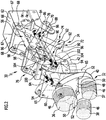
- the wheel washing devices 30 are designed to be functionally identical, so that in the following only with reference to the Figures 2 to 6 one of the wheel washers 30, which is explained in Figure 1 Wheel washing device shown on the right. For the other, in Figure 1 The wheel washing device 30 shown on the left applies accordingly.
- the wheel washing device 30 comprises a brush device 32 and a feed device 34 in order to move the brush device 32 from a rest position away from the wheel ( Figure 3 ) in at least one position of use close to the wheel ( Figure 4 ) and vice versa.
- the brush device 32 can be designed in different ways, for example at least one brush is provided for contact with the wheel 16.
- the at least one brush can have cleaning elements, in particular in the form of cleaning bristles.
- the brush device 32 comprises three brushes 36, 37, 38 which are held on a brush holder 40.
- the brush holder 40 forms a housing in which a gear (not shown) driven by a drive device 42 for the brush device 32 is received.
- the structure of the transmission and the holders of the brushes 36, 37, 38 and their design in detail can be different, for example as in the one mentioned at the beginning WO 2012/110094 A1 described.
- the brush holder 40 rotates about a central brush axis 44. In this way, the brushes 36, 37, 38 rotate about the brush axis 44, the brushes 36, 37, 38 additionally rotating about their own axis under the action of the gear carry out.
- the brushes 36, 37, 38 each have cleaning bristles 46 for contact with the wheel 16.
- the brush device 32 comprises a distribution device 48 for cleaning liquid.
- the distribution device 48 comprises, for example, at least one spray arm 50 with a nozzle 52 arranged thereon.
- Cleaning liquid, in particular water, which is applied to the distribution device 48, can be directed onto the wheel 16 via the nozzles 52 to increase the cleaning effect.
- the infeed device 34 comprises a holding device 54 and an adjusting device 56.
- the adjusting device 56 and the drive device 42 can be controlled, for example, by a control device 58 that is part of the wheel washing device 30 or preferably part of the vehicle washing system 10 for controlling its other functions and processes.
- the holding device 54 comprises a first holding part 60 and a second holding part 62 arranged at a distance therefrom.
- the holding part 60 is used to hold the brush device 32 and the drive device 42.
- the brush device 32 and the drive device 42 are on the opposite sides of the holding part 60 set.
- the brush device 32 can of course execute the rotary movement about the brush axis 44 caused by the drive device 42.
- the holding part 60 has an essentially plate-shaped central section 64 and lateral sections 65 on opposite sides of the central section 64.
- the holding part 60 is made from an edged sheet metal part.
- the holding part 60 is arranged on a first side of the holding device 54 facing the brush device 32, the holding part 62 is on an opposite side of the holding device facing away from the brush device 32 54 arranged.
- the wheel washing device 30 is fixed to the support device 26 of the washing portal via the holding part 62.
- the second holding part 62 in the present case comprises a middle section 66 and lateral sections 67 on opposite sides of the middle section 66.
- the holding part 62 is manufactured as a bent sheet metal part.
- the holding part 62 comprises two tongue-like projections 68, 70 on the respective lateral section 67 in the direction of the holding part 60.
- the lower projection 70 is longer than the upper projection 68.
- the holding part 62 could also be designed without projections 68, 70.
- the infeed device 34 comprises a guide device 72.
- the guide device 72 is formed by the holding device 54.
- the guide device 72 comprises two joint arrangements 74, 76.
- the joint arrangements 74, 76 are designed to be functionally identical. Identical reference symbols are therefore used for the components of the joint arrangements 74, 76. The following essentially deals with the joint arrangement 74, the explanations correspondingly applying to the joint arrangement 76.
- the hinge arrangement 74 comprises at least one scissor hinge and, in the present case, two scissor hinges 78, 80.
- the scissor hinges 78, 80 are arranged in series, so that the guide device 72 as a whole forms a scissor pull 82.
- the scissors joint 78 comprises joint members 84, 86 which are pivotable relative to one another and are connected crosswise to one another.
- the joint member 84 is articulated on the projection 68.
- the joint member 86 is not articulated on the projection 70.
- a further joint member 88 of the joint arrangement 74 is provided, which is articulated on the projection 70 and on the joint member 86.
- the scissors joint 80 comprises joint members 90, 92 which can be pivoted relative to one another and are cross-connected to one another.
- the joint member 90 is articulated to the joint member 86 on the side facing away from the joint member 88.
- the joint member 90 is articulated to the holding part 60 via a further joint member 94 of the joint arrangement 74.
- the joint member 94 is accordingly articulated on the holding part 60 and on the joint member 90.
- the joint member 92 is hinged to the joint member 84 on the side facing away from the projection 68. With the side facing away from this, the joint member 92 is articulated on the holding part 60.
- the corresponding joint members 84, 86, 90 and 92 of the joint arrangements 74, 76 are connected to one another via a respective connecting member 96.
- the respective combination of joint links 84, 86, 90, 92 and the corresponding connecting link 96 is bow-shaped or U-shaped ( Figure 2 ).
- the adjusting device 56 comprises a pneumatically or hydraulically actuated piston-cylinder unit 98 with a first end, which is formed by the cylinder, and a second end, which is formed by the piston.
- the first end of the piston-cylinder unit 98 is fixed to the holding part 62, in particular its middle section 66.
- the second end of the piston-cylinder unit 98 is coupled to the joint arrangements 74, 76.
- a coupling member 100 is provided for this purpose.
- the coupling member 100 is designed in the shape of a bow and is articulated to joint members of the joint arrangements 74, 76. These are the joint members 90. It would be possible for the adjusting device 56 to act on only one of the joint arrangements 74, 76. Gripping the holding part 60 is also conceivable.
- the infeed device 34 furthermore comprises at least one restoring element which acts against the piston-cylinder unit 98 of the adjusting device 56.
- several restoring elements 102 in the form of spring elements 104 are provided.
- the spring elements 104 are designed as tension-acting helical springs.
- the spring elements 104 act on two joint members of the joint arrangements 74, 76 that are movable relative to one another.
- two spring elements 104 act on the joint members 84, 90 of each joint arrangement 74, 76.
- the wheel washing device 30 has an overall compact design. The construction is relatively light and robust at the same time.
- the piston-cylinder unit 98, the drive device 42 and the spring elements 104 are arranged between the joint arrangements 74, 76, which favors the compact design.
- the brush device 32 can be an in Figure 3 Assume the rest position shown when the wheel washing device 30 is not in use.
- the piston-cylinder unit 98 assumes a shortened configuration when the piston is retracted.
- the scissor joints 78, 80 are retracted in such a way that the brush device 32 is positioned as close as possible to the holding part 62.
- the brush device 32 can thus be stored in a space-saving manner.
- the piston-cylinder unit 98 is extended.
- the holding device 54 is deformed by pivoting the joint members relative to one another.
- the scissor joints 78, 80 are extended and the brush device 32 is brought at a greater distance from the holding part 62.
- the movement of the brush device 32 does not take place in a straight line. This is based on the fact that the scissor train 82 is not only lengthened, but also its inclination changes as a function of the length of the scissor train 82. The reason for this is the articulation of the scissors joint 78 on the holding part 62 via the joint member 88 and the articulation of the scissors joint 80 on the holding part 60 via the joint member 94.
- the brush device 32 can be moved along a trajectory 106, starting from the rest position up to a maximally extended use position. In this case, the brush device 32 is lowered when it moves in the direction of the wheel 16. The movement of the brush device 32 does not take place in a straight line, but in an arcuate manner.
- the Figures 3 , 5 and 6 as well as the Figures 7 , 9 , 10 and 11 For the embodiments explained below, they also show schematically a coordinate system to clarify the course of the trajectory 106.
- the brush device 32 runs through the trajectory 106 entirely or only partially during delivery. This depends on the position of the wheel relative to the wheel washing device 30. The diameter of the wheel also determines whether the brush device 32 is aligned coaxially with the wheel when the brushes 36, 37, 38 are applied to the wheel.
- the Figures 3 to 5 show by way of example how the brush device 32 can be extended into a maximally extended position of use for cleaning the wheel 16 in order to reproduce the entire course of the trajectory 106.
- the infeed device 34 is designed such that the trajectory 106, along which the brush device 32 is moved, has at least one turning point 108 has. Exactly one turning point 108 is provided in the present case.
- the turning point 108 lies approximately in the area of the middle of the trajectory 106 between the rest position of the brush device 32 and its maximally extended position of use. Starting from the rest position, the brush device 32 can be moved in an arc-shaped manner up to the turning point 108 in the direction of the installation surface 14, the curvature of the concave trajectory 106 points in the direction of the installation surface 14 of the trajectory 106, the curvature of the convex trajectory 106 points away from the installation surface 14.
- the trajectory 106 starting from the rest position of the brush device 32, is approximately cosine-shaped.
- the brush device 32 can be moved approximately parallel to the installation surface 14 and in particular approximately horizontally.
- the movement of the brush device 32 takes place in or essentially in a plane perpendicular to the installation surface 14, in particular in a vertical plane.
- a correctly positioned delivery in which the brush axis 44 ideally with the wheel axis 110 is in the Figures 3 to 5 shown using the example of wheel 16.
- Figure 6 shows the situation with the wheel 20 which is larger in relation to the wheel 16 and which is also arranged closer to the wheel washing device 30 due to the wider motor vehicle 18.
- the brush device 32 runs through only part of the trajectory 106, for example approximately up to the turning point 108.
- a position-correct delivery takes place, in which the brush axis 44 is aligned with the wheel axis 110.
- the brush device 32 traverses an even smaller part of the trajectory 106, for example not even as far as the turning point 108.
- the infeed device 34 comprises a holding device 122, the adjusting device 56 and a guide device 124.
- the holding device 122 has a holding frame 126 with holding parts 128, 130.
- the holding part 128 corresponds to the holding part 60 and is used to fix the brush device 32.
- the holding part 130 extends from the holding part 128 in a direction facing away from the brush device.
- the drive device 42 is held on the holding part 130 and on the holding part 128.
- the guide device 124 comprises a positive guide for the holding frame 126.
- the positive guide is designed as a guide link.
- a total of four guide slots 132 are provided, with two guide slots 132, for example, being arranged on each of the two sides of the holding frame 126. Of these are in the Figures 7 and 8 two guide links 132 are shown.
- the two guide slots 132 arranged on one side are firmly connected to one another.
- a guide slot 132 is fixed on the support device 26. This is in the Figures 7 and 8 shown schematically.
- the cylinder of the piston-cylinder unit 98 also engages on the support device 26. An articulated connection is advantageously provided here.
- the opposite end of the piston-cylinder unit 98 is preferably connected in an articulated manner to the holding part 128.
- the guide slot 132 is, for example, plate-shaped and comprises a slot track 134.
- the slot track 134 defines the course of the path curve 106.
- the guide device 124 is designed in such a way that the trajectory 106 has at least one turning point 108.
- the guide device 124 is designed in such a way that the trajectory 106 has at least one turning point 108.
- the Figures 8 and 9 show the brush device 32 in a maximally extended position of use, resting on the wheel 16, the brush axis 44 being aligned with the wheel axis 110.
- Figure 10 shows one of the Figure 6 Corresponding example in which the brush device 32 is only partially extended along the trajectory 106 and makes contact with the wheel 20.
- the brush axis 44 coincides with the wheel axis 110.
- the brush device 32 traverses an even smaller part of the trajectory 106, for example not even as far as the turning point 108.
- the infeed device 34 comprises a holding device 142 and the adjusting device 56.
- the holding device 142 has a holding part 144, which corresponds in its function to the holding parts 60 and 128, respectively.
- the brush device 32 and the drive device 42 are fixed on opposite sides of the holding device 142.
- the adjustment device 56 comprises two drive units 146, 148.
- the drive unit 146 is fixed to the support device 26 of the washing portal and is coupled to the drive unit 148 via a coupling element 150.
- the drive unit 148 is coupled to the holding part 144 via a coupling element 152.
- the drive units 146, 148 can be controlled by the control device 58.
- the brush device 32 can be advanced by actuating the drive units 146, 148.
- the brush device 32 along the trajectory 106 is movable with at least one turning point 108, starting from the rest position into a maximally extended position of use.
- the trajectory 106 For a more detailed possible configuration of the trajectory 106, reference is made to the above statements on the wheel washing device 30.
- the brush device 32 is moved along two directions defined by double arrows 154 and 156, it being possible for the drive unit 146 to move in the direction 154 and the drive unit 148 to move in the direction 156.
- the directions 154, 156 are oriented at an angle to one another and preferably perpendicular to one another.
- the direction 154 can be perpendicular to the installation surface 14 and the direction 156 parallel to the installation surface 14, i.e. in particular the directions 154, 156 are oriented vertically or horizontally.
- a supply line 160 for a cleaning fluid can be provided.
- the distribution device 48 can be supplied with cleaning fluid via the supply line 160.
- the example of the wheel washing device 120 shows that the supply line 160 is advantageously held on the holding device 122. The same can be provided for the holding device 54 of the wheel washing device 30 and the holding device 142 of the wheel washing device 140.
Landscapes
- Engineering & Computer Science (AREA)
- Mechanical Engineering (AREA)
- Vehicle Cleaning, Maintenance, Repair, Refitting, And Outriggers (AREA)
- Cleaning In General (AREA)
Claims (16)
- Dispositif de lavage de roue pour nettoyer une roue d'un véhicule à moteur, comprenant un système de brosse (32), qui comprend ou forme au moins une brosse (36, 37, 38) pouvant être placée sur la roue (16, 20), un système d'entraînement (42) pour l'entraînement en rotation de l'au moins une brosse (36, 37, 38) et un système d'avance (34), avec lequel le système de brosse (32) peut être amené d'une position de repos éloignée de la roue dans au moins une position d'utilisation proche de la roue, dans lequel le système de brosse (32) peut être abaissé au moyen du système d'avance (34) lors d'un mouvement en direction de la roue (16, 20), caractérisé en ce que le système de brosse (32) est mobile au moyen du système d'avance (34) lors d'un mouvement d'avance de la position de repos dans l'au moins une position d'utilisation le long d'une trajectoire (106) présentant au moins un point d'inflexion (108) et parcourt cette trajectoire (106) lors du mouvement d'avance.
- Dispositif de lavage de roue selon la revendication 1, caractérisé en ce qu'au moins un de ce qui suit s'applique :- le système de brosse (32) est mobile le long d'une trajectoire (106) présentant précisément un point d'inflexion (108) ;- l'au moins un point d'inflexion (108) est disposé au centre ou sensiblement au centre de la trajectoire (106) entre la position de repos et une position d'utilisation du système de brosse (32) sortie au maximum par rapport à la position de repos ;- le système de brosse (32) est mobile à partir de la position de repos jusqu'à au moins un point d'inflexion (108) et/ou à partir d'au moins un point d'inflexion (108) jusqu'à une position d'utilisation du système de brosse (32) sortie au maximum par rapport à la position de repos le long d'une trajectoire (106) arquée.
- Dispositif de lavage de roue selon l'une quelconque des revendications précédentes, caractérisé en ce que le système de brosse (32) est mobile le long d'une trajectoire (106) sensiblement à symétrie ponctuelle par rapport à l'au moins un point d'inflexion (108) et/ou que le système de brosse (32) est mobile le long d'une trajectoire (106) à peu près cosinusoïdale à partir de la position de repos.
- Dispositif de lavage de roue selon l'une quelconque des revendications précédentes, caractérisé en ce que le système de brosse (32) lors du mouvement à partir de la position de repos et/ou lors de l'amenée dans une position d'utilisation sortie au maximum par rapport à la position de repos est mobile parallèlement ou sensiblement parallèlement à une surface de pose (14) pour le véhicule à moteur (12, 18) et/ou que le système de brosse (32) est mobile dans un plan orienté perpendiculairement ou sensiblement perpendiculairement à une surface de pose (14) pour le véhicule à moteur (12, 18).
- Dispositif de lavage de roue selon l'une quelconque des revendications précédentes, caractérisé en ce que le système d'avance (34) comprend un système de retenue (54 ; 122 ; 142), sur lequel le système de brosse (32) est fixé, et un système de déplacement (56) accouplé au système de retenue (54 ; 122 ; 142) pour amener le système de brosse (32) de la position de repos dans l'au moins une position d'utilisation.
- Dispositif de lavage de roue selon la revendication 5, caractérisé en ce que le système de déplacement (56) est conçu de manière électrique, mécanique, pneumatique et/ou hydraulique, en particulier que le système de déplacement (56) comprend ou réalise au moins un groupe à piston-cylindre (98), et/ou que le système d'avance (34) comprend un système de guidage (72) pour le guidage du mouvement du système de brosse (32).
- Dispositif de lavage de roue selon la revendication 6, caractérisé en ce qu'au moins un de ce qui suit s'applique :- le système de guidage (72) comprend au moins une coulisse de guidage (132), dans laquelle s'insère au moins un organe de guidage (136) du système de retenue (122) et dont le tracé définit la trajectoire (106), dans lequel de préférence deux coulisses de guidage (132) disposées à distance l'une de l'autre sont prévues, entre lesquelles le système de retenue (122) est disposé ;- le système de retenue (54) comprend le système de guidage (72) ou réalise celui-ci.
- Dispositif de lavage de roue selon l'une quelconque des revendications 5 à 7, caractérisé en ce que le système de guidage (72) comprend au moins un ensemble d'articulation (74, 76) avec des organes d'articulation (84, 86, 88, 90, 92, 94) pouvant pivoter les uns par rapport aux autres, sur lesquels le système de brosse (32) est fixé directement ou indirectement par l'intermédiaire d'une pièce de retenue (60) du système de retenue (54), de préférence que l'ensemble d'articulation (74, 76) comprend ou réalise au moins une articulation à ciseaux (78, 80), dont les branches sont les organes d'articulation (84, 86, 90, 92).
- Dispositif de lavage de roue selon la revendication 8, caractérisé en ce qu'au moins un de ce qui suit s'applique :- deux articulations à ciseaux (78, 80) ou plus disposées en série sont présentes ;- l'ensemble d'articulation (74, 76) comprend un organe d'articulation (94), qui est relié de manière articulée à l'une des branches et au système de brosse (32) ou à la pièce de retenue (60) ;- l'ensemble d'articulation (74, 76) comprend un organe d'articulation (88), qui est relié de manière articulée à l'une des branches et à une pièce de retenue (62) du système de retenue (54), par l'intermédiaire duquel le système de retenue (54) est fixé à un système de support (26) pour la pose du dispositif de lavage de roue (30) sur une surface de pose (14) pour le véhicule à moteur (12, 18).
- Dispositif de lavage de roue selon la revendication 8 ou 9, caractérisé en ce que deux ensembles d'articulation (74, 76) disposés à distance l'un de l'autre sont prévus, entre lesquels le système de déplacement (56) et/ou le système d'entraînement (42) pour le système de brosse (32) est disposé, de préférence que les ensembles d'articulation (74, 76) sont conçus avec une fonction équivalente, dans lequel des organes d'articulation (84, 86, 90, 92) correspondant les uns aux autres des ensembles d'articulation (74, 76) sont reliés les uns aux autres par un organe de liaison (96).
- Dispositif de lavage de roue selon l'une quelconque des revendications 8 à 10, caractérisé en ce que le système de déplacement (56) est accouplé directement ou indirectement à au moins un organe d'articulation (90) de l'au moins un ensemble d'articulation (74, 76), de préférence qu'un organe d'accouplement (100) en forme d'étrier est prévu, qui est fixé par articulation sur des organes d'articulation (90) des deux ensembles d'articulation (74, 76).
- Dispositif de lavage de roue selon l'une quelconque des revendications 5 à 11, caractérisé en ce qu'au moins un de ce qui suit s'applique :- le système d'avance (34) comprend au moins un élément de rappel (102) agissant à l'encontre de l'action du système de déplacement (56), qui est conçu de préférence sous la forme d'un élément ressort (104) ;- le système de déplacement (56) présente deux unités d'entraînement (146, 148) pour le mouvement du système de retenue (142) dans deux directions (154, 156) orientées à un angle l'une par rapport à l'autre, dans lequel le mouvement du système de brosse (32) le long de la trajectoire (106) peut être commandé par commande des unités d'entraînement (146, 148), dans lequel les directions (154, 156) sont orientées de préférence perpendiculairement ou sensiblement perpendiculairement l'une à l'autre et les directions (154, 156) sont orientées en particulier parallèlement et perpendiculairement à une surface de pose (14) pour le véhicule à moteur (12, 18) ;- le système d'entraînement (42) est fixé sur le système de retenue (54 ; 122 ; 142).
- Dispositif de lavage de roue selon la revendication 12, caractérisé en ce que l'au moins un élément de rappel (102) est disposé entre les ensembles d'articulation (74, 76) et/ou que l'au moins un élément de rappel (102) précontraint des organes d'articulation (84, 90) de l'au moins un ensemble d'articulation (74, 76) l'un par rapport à l'autre en direction de la position de repos du système de brosse (32).
- Dispositif de lavage de roue selon l'une quelconque des revendications précédentes, caractérisé en ce que le système de brosse (32) présente un système de répartition (48) pour un liquide de nettoyage et/ou qu'une conduite d'amenée (160) pour un liquide de nettoyage est retenue sur le système de retenue (54 ; 122 ; 142).
- Installation de lavage de véhicule, en particulier installation de lavage à portique, comprenant au moins un dispositif de lavage de roue (30 ; 120 ; 140) pour le nettoyage d'une roue (16, 20) selon l'une quelconque des revendications précédentes.
- Procédé pour nettoyer une roue d'un véhicule à moteur, selon lequel un système de brosse, qui comprend ou réalise au moins une brosse pouvant être placée sur la roue, est amené au moyen d'un système d'avance d'une position de repos éloignée de la roue dans une position d'utilisation proche de la roue et ce faisant abaissé, dans lequel le système de brosse est déplacé dans un mouvement d'avance le long d'une trajectoire présentant au moins un point d'inflexion de la position de repos dans la position d'utilisation.
Applications Claiming Priority (1)
| Application Number | Priority Date | Filing Date | Title |
|---|---|---|---|
| PCT/EP2017/058389 WO2018184691A1 (fr) | 2017-04-07 | 2017-04-07 | Arrangement de lavage de roue et procédé de nettoyage d'une roue ainsi qu'installation de lavage pour véhicules |
Publications (2)
| Publication Number | Publication Date |
|---|---|
| EP3606794A1 EP3606794A1 (fr) | 2020-02-12 |
| EP3606794B1 true EP3606794B1 (fr) | 2021-10-13 |
Family
ID=58536970
Family Applications (1)
| Application Number | Title | Priority Date | Filing Date |
|---|---|---|---|
| EP17716851.5A Active EP3606794B1 (fr) | 2017-04-07 | 2017-04-07 | Arrangement de lavage de roue et procédé de nettoyage d'une roue ainsi qu'installation de lavage pour véhicules |
Country Status (6)
| Country | Link |
|---|---|
| US (1) | US20200031320A1 (fr) |
| EP (1) | EP3606794B1 (fr) |
| CN (1) | CN110325412B (fr) |
| BR (1) | BR112019013416A2 (fr) |
| ES (1) | ES2898825T3 (fr) |
| WO (1) | WO2018184691A1 (fr) |
Families Citing this family (5)
| Publication number | Priority date | Publication date | Assignee | Title |
|---|---|---|---|---|
| DE102016122802A1 (de) * | 2016-11-25 | 2018-05-30 | Washtec Holding Gmbh | Verfahren zum Betrieb einer Fahrzeugwaschanlage und Fahrzeugwaschanlage |
| ES2819326B2 (es) | 2019-10-14 | 2021-11-23 | Istobal Sa | Dispositivo de lavado de ruedas |
| CN112158171B (zh) * | 2020-10-13 | 2022-03-29 | 山东交通学院 | 一种轮胎清理装置 |
| CN113447239A (zh) * | 2021-06-25 | 2021-09-28 | 南京交运汽车综合性能检测有限公司 | 汽车灯光检测装置及方法 |
| CN113771802B (zh) * | 2021-09-23 | 2023-06-23 | 杭州市公共交通集团有限公司 | 一种车轮钢圈就车清洗设备 |
Citations (1)
| Publication number | Priority date | Publication date | Assignee | Title |
|---|---|---|---|---|
| EP2332793A1 (fr) * | 2009-12-09 | 2011-06-15 | Carlo Sesia | Dispositif de lavage de roues |
Family Cites Families (6)
| Publication number | Priority date | Publication date | Assignee | Title |
|---|---|---|---|---|
| CN2808672Y (zh) * | 2005-07-19 | 2006-08-23 | 徐建生 | 电脑全自动洗车机的跟走轮刷装置 |
| DE202008012139U1 (de) * | 2008-09-11 | 2010-02-11 | Washtec Holding Gmbh | Vorrichtung zum Reinigen eines Rads eines Fahrzeugs in einer Fahrzeugwaschanlage |
| DE102010036190A1 (de) * | 2010-09-02 | 2012-03-08 | Wash Tec Holding Gmbh | Vorrichtung und Verfahren zum Aufbringen von Reinigungsflüssigkeit auf ein Rad eines Fahrzeugs in einer Fahrzeugwaschanlage und Fahrzeugwaschanlage |
| CN204870945U (zh) * | 2015-08-19 | 2015-12-16 | 南京海天洗车设备制造有限公司 | 可倾斜旋转高压水轮刷机构 |
| CN205417547U (zh) * | 2016-02-03 | 2016-08-03 | 特科能(株洲)科技有限公司 | 洗车机轮毂清洗装置 |
| CN205854100U (zh) * | 2016-07-27 | 2017-01-04 | 东莞市赛力自动化设备科技股份有限公司 | 一种洗车机清洗轮毂的毛刷运动装置 |
-
2017
- 2017-04-07 WO PCT/EP2017/058389 patent/WO2018184691A1/fr not_active Ceased
- 2017-04-07 BR BR112019013416-6A patent/BR112019013416A2/pt not_active Application Discontinuation
- 2017-04-07 EP EP17716851.5A patent/EP3606794B1/fr active Active
- 2017-04-07 CN CN201780086734.8A patent/CN110325412B/zh active Active
- 2017-04-07 ES ES17716851T patent/ES2898825T3/es active Active
-
2019
- 2019-10-02 US US16/590,708 patent/US20200031320A1/en not_active Abandoned
Patent Citations (1)
| Publication number | Priority date | Publication date | Assignee | Title |
|---|---|---|---|---|
| EP2332793A1 (fr) * | 2009-12-09 | 2011-06-15 | Carlo Sesia | Dispositif de lavage de roues |
Also Published As
| Publication number | Publication date |
|---|---|
| CN110325412B (zh) | 2023-04-04 |
| EP3606794A1 (fr) | 2020-02-12 |
| WO2018184691A1 (fr) | 2018-10-11 |
| CN110325412A (zh) | 2019-10-11 |
| ES2898825T3 (es) | 2022-03-09 |
| US20200031320A1 (en) | 2020-01-30 |
| BR112019013416A2 (pt) | 2020-03-03 |
Similar Documents
| Publication | Publication Date | Title |
|---|---|---|
| EP3606794B1 (fr) | Arrangement de lavage de roue et procédé de nettoyage d'une roue ainsi qu'installation de lavage pour véhicules | |
| DE19921435A1 (de) | Scherenhubtisch | |
| EP3263241B1 (fr) | Dispositif de repliage à rouleaux et procédé de repliage d'une zone de rebord d'une pièce de tôlerie | |
| DE10042991A1 (de) | Gelenkarm-Transportsystem | |
| EP2526038B1 (fr) | Système de convoyage pour le transport d'objects et installation de traitement par immersion équipée d'un système de ce type | |
| DE3041472C2 (de) | Gleisbaumaschine mit einer mechanischen Einrichtung für die Korrektur des Gleises | |
| DE1580769C3 (de) | Anordung zum Waschen von Fahrzeugen in Fahrzeugwaschanlage n | |
| EP3442724B1 (fr) | Procédé et dispositif de redressage d'une pièce | |
| EP3995366A1 (fr) | Dispositif de fixation de brosse pour une installation de lavage de véhicules et installation de lavage de véhicules | |
| DE10142131B4 (de) | Vorrichtung zum Anbringen von Dichtungsprofilen an Fahrzeugtüren | |
| EP3475129B1 (fr) | Dispositif de séchage pour véhicules à moteur et installation de lavage des véhicules pourvue d'un dispositif de séchage | |
| DE202016101927U1 (de) | Bürstenschwenkvorrichtung, Seitenwaschbürste und damit ausgestattete Fahrzeugwaschanlage | |
| AT518262B1 (de) | Abkantpresse | |
| EP0060387B1 (fr) | Dispositif de lavage, notamment pour panneaux d'autoroutes | |
| DE2633683C2 (de) | Transportfahrzeug für Fertiggaragen und dergleichen | |
| DE102019211533B4 (de) | Verteilstation sowie Verfahren zum Betrieb einer Verteilstation für eine automatisierte Herstellung eines Kabelsatzes | |
| DE102013220149B4 (de) | Bodenreinigungsmaschine mit Transportsicherung für Seitenbesen | |
| DE102017111433A1 (de) | Trocknungsvorrichtung für Fahrzeuge, Fahrzeugwaschanlage und Verfahren zum Trocknen eines Fahrzeugs | |
| WO2006027083A1 (fr) | Ensemble buses pour une installation de lavage de vehicules et procede de lavage de vehicule | |
| EP2550187B1 (fr) | Auxiliaire d'acces et installation de traitement de vehicule | |
| DE102019119709B4 (de) | Transportwagen | |
| DE3515255A1 (de) | Vorrichtung zum entnehmen und weiterleiten eines spritzgussteiles bei einer spritzgiessmaschine | |
| WO2016055327A1 (fr) | Appareil de préparation de boissons | |
| EP4003794B1 (fr) | Dispositif de portique pour une installation de manutention de véhicules et installation de manutention de véhicules | |
| EP3793870B1 (fr) | Systeme de lavage de vehicules avec un dispositif de pulverisation |
Legal Events
| Date | Code | Title | Description |
|---|---|---|---|
| STAA | Information on the status of an ep patent application or granted ep patent |
Free format text: STATUS: UNKNOWN |
|
| STAA | Information on the status of an ep patent application or granted ep patent |
Free format text: STATUS: THE INTERNATIONAL PUBLICATION HAS BEEN MADE |
|
| PUAI | Public reference made under article 153(3) epc to a published international application that has entered the european phase |
Free format text: ORIGINAL CODE: 0009012 |
|
| STAA | Information on the status of an ep patent application or granted ep patent |
Free format text: STATUS: REQUEST FOR EXAMINATION WAS MADE |
|
| 17P | Request for examination filed |
Effective date: 20190730 |
|
| AK | Designated contracting states |
Kind code of ref document: A1 Designated state(s): AL AT BE BG CH CY CZ DE DK EE ES FI FR GB GR HR HU IE IS IT LI LT LU LV MC MK MT NL NO PL PT RO RS SE SI SK SM TR |
|
| AX | Request for extension of the european patent |
Extension state: BA ME |
|
| RIN1 | Information on inventor provided before grant (corrected) |
Inventor name: DOEBELE, JOHANNES Inventor name: HEINZE, MICHAEL Inventor name: HEID, CLAUS |
|
| DAV | Request for validation of the european patent (deleted) | ||
| DAX | Request for extension of the european patent (deleted) | ||
| STAA | Information on the status of an ep patent application or granted ep patent |
Free format text: STATUS: EXAMINATION IS IN PROGRESS |
|
| 17Q | First examination report despatched |
Effective date: 20201023 |
|
| GRAP | Despatch of communication of intention to grant a patent |
Free format text: ORIGINAL CODE: EPIDOSNIGR1 |
|
| STAA | Information on the status of an ep patent application or granted ep patent |
Free format text: STATUS: GRANT OF PATENT IS INTENDED |
|
| INTG | Intention to grant announced |
Effective date: 20210527 |
|
| GRAS | Grant fee paid |
Free format text: ORIGINAL CODE: EPIDOSNIGR3 |
|
| GRAA | (expected) grant |
Free format text: ORIGINAL CODE: 0009210 |
|
| STAA | Information on the status of an ep patent application or granted ep patent |
Free format text: STATUS: THE PATENT HAS BEEN GRANTED |
|
| AK | Designated contracting states |
Kind code of ref document: B1 Designated state(s): AL AT BE BG CH CY CZ DE DK EE ES FI FR GB GR HR HU IE IS IT LI LT LU LV MC MK MT NL NO PL PT RO RS SE SI SK SM TR |
|
| REG | Reference to a national code |
Ref country code: GB Ref legal event code: FG4D Free format text: NOT ENGLISH |
|
| REG | Reference to a national code |
Ref country code: CH Ref legal event code: EP |
|
| REG | Reference to a national code |
Ref country code: DE Ref legal event code: R096 Ref document number: 502017011722 Country of ref document: DE |
|
| REG | Reference to a national code |
Ref country code: IE Ref legal event code: FG4D Free format text: LANGUAGE OF EP DOCUMENT: GERMAN |
|
| REG | Reference to a national code |
Ref country code: AT Ref legal event code: REF Ref document number: 1437979 Country of ref document: AT Kind code of ref document: T Effective date: 20211115 |
|
| REG | Reference to a national code |
Ref country code: LT Ref legal event code: MG9D |
|
| REG | Reference to a national code |
Ref country code: NL Ref legal event code: MP Effective date: 20211013 |
|
| REG | Reference to a national code |
Ref country code: DE Ref legal event code: R082 Ref document number: 502017011722 Country of ref document: DE Representative=s name: DTS PATENT- UND RECHTSANWAELTE SCHNEKENBUEHL U, DE Ref country code: DE Ref legal event code: R082 Ref document number: 502017011722 Country of ref document: DE Representative=s name: DTS PATENT- UND RECHTSANWAELTE PARTMBB, DE |
|
| REG | Reference to a national code |
Ref country code: ES Ref legal event code: FG2A Ref document number: 2898825 Country of ref document: ES Kind code of ref document: T3 Effective date: 20220309 |
|
| PG25 | Lapsed in a contracting state [announced via postgrant information from national office to epo] |
Ref country code: RS Free format text: LAPSE BECAUSE OF FAILURE TO SUBMIT A TRANSLATION OF THE DESCRIPTION OR TO PAY THE FEE WITHIN THE PRESCRIBED TIME-LIMIT Effective date: 20211013 Ref country code: LT Free format text: LAPSE BECAUSE OF FAILURE TO SUBMIT A TRANSLATION OF THE DESCRIPTION OR TO PAY THE FEE WITHIN THE PRESCRIBED TIME-LIMIT Effective date: 20211013 Ref country code: FI Free format text: LAPSE BECAUSE OF FAILURE TO SUBMIT A TRANSLATION OF THE DESCRIPTION OR TO PAY THE FEE WITHIN THE PRESCRIBED TIME-LIMIT Effective date: 20211013 Ref country code: BG Free format text: LAPSE BECAUSE OF FAILURE TO SUBMIT A TRANSLATION OF THE DESCRIPTION OR TO PAY THE FEE WITHIN THE PRESCRIBED TIME-LIMIT Effective date: 20220113 |
|
| PG25 | Lapsed in a contracting state [announced via postgrant information from national office to epo] |
Ref country code: IS Free format text: LAPSE BECAUSE OF FAILURE TO SUBMIT A TRANSLATION OF THE DESCRIPTION OR TO PAY THE FEE WITHIN THE PRESCRIBED TIME-LIMIT Effective date: 20220213 Ref country code: SE Free format text: LAPSE BECAUSE OF FAILURE TO SUBMIT A TRANSLATION OF THE DESCRIPTION OR TO PAY THE FEE WITHIN THE PRESCRIBED TIME-LIMIT Effective date: 20211013 Ref country code: PT Free format text: LAPSE BECAUSE OF FAILURE TO SUBMIT A TRANSLATION OF THE DESCRIPTION OR TO PAY THE FEE WITHIN THE PRESCRIBED TIME-LIMIT Effective date: 20220214 Ref country code: PL Free format text: LAPSE BECAUSE OF FAILURE TO SUBMIT A TRANSLATION OF THE DESCRIPTION OR TO PAY THE FEE WITHIN THE PRESCRIBED TIME-LIMIT Effective date: 20211013 Ref country code: NO Free format text: LAPSE BECAUSE OF FAILURE TO SUBMIT A TRANSLATION OF THE DESCRIPTION OR TO PAY THE FEE WITHIN THE PRESCRIBED TIME-LIMIT Effective date: 20220113 Ref country code: NL Free format text: LAPSE BECAUSE OF FAILURE TO SUBMIT A TRANSLATION OF THE DESCRIPTION OR TO PAY THE FEE WITHIN THE PRESCRIBED TIME-LIMIT Effective date: 20211013 Ref country code: LV Free format text: LAPSE BECAUSE OF FAILURE TO SUBMIT A TRANSLATION OF THE DESCRIPTION OR TO PAY THE FEE WITHIN THE PRESCRIBED TIME-LIMIT Effective date: 20211013 Ref country code: HR Free format text: LAPSE BECAUSE OF FAILURE TO SUBMIT A TRANSLATION OF THE DESCRIPTION OR TO PAY THE FEE WITHIN THE PRESCRIBED TIME-LIMIT Effective date: 20211013 Ref country code: GR Free format text: LAPSE BECAUSE OF FAILURE TO SUBMIT A TRANSLATION OF THE DESCRIPTION OR TO PAY THE FEE WITHIN THE PRESCRIBED TIME-LIMIT Effective date: 20220114 |
|
| REG | Reference to a national code |
Ref country code: DE Ref legal event code: R097 Ref document number: 502017011722 Country of ref document: DE |
|
| PG25 | Lapsed in a contracting state [announced via postgrant information from national office to epo] |
Ref country code: SM Free format text: LAPSE BECAUSE OF FAILURE TO SUBMIT A TRANSLATION OF THE DESCRIPTION OR TO PAY THE FEE WITHIN THE PRESCRIBED TIME-LIMIT Effective date: 20211013 Ref country code: SK Free format text: LAPSE BECAUSE OF FAILURE TO SUBMIT A TRANSLATION OF THE DESCRIPTION OR TO PAY THE FEE WITHIN THE PRESCRIBED TIME-LIMIT Effective date: 20211013 Ref country code: RO Free format text: LAPSE BECAUSE OF FAILURE TO SUBMIT A TRANSLATION OF THE DESCRIPTION OR TO PAY THE FEE WITHIN THE PRESCRIBED TIME-LIMIT Effective date: 20211013 Ref country code: EE Free format text: LAPSE BECAUSE OF FAILURE TO SUBMIT A TRANSLATION OF THE DESCRIPTION OR TO PAY THE FEE WITHIN THE PRESCRIBED TIME-LIMIT Effective date: 20211013 Ref country code: DK Free format text: LAPSE BECAUSE OF FAILURE TO SUBMIT A TRANSLATION OF THE DESCRIPTION OR TO PAY THE FEE WITHIN THE PRESCRIBED TIME-LIMIT Effective date: 20211013 Ref country code: CZ Free format text: LAPSE BECAUSE OF FAILURE TO SUBMIT A TRANSLATION OF THE DESCRIPTION OR TO PAY THE FEE WITHIN THE PRESCRIBED TIME-LIMIT Effective date: 20211013 |
|
| PLBE | No opposition filed within time limit |
Free format text: ORIGINAL CODE: 0009261 |
|
| STAA | Information on the status of an ep patent application or granted ep patent |
Free format text: STATUS: NO OPPOSITION FILED WITHIN TIME LIMIT |
|
| 26N | No opposition filed |
Effective date: 20220714 |
|
| PG25 | Lapsed in a contracting state [announced via postgrant information from national office to epo] |
Ref country code: AL Free format text: LAPSE BECAUSE OF FAILURE TO SUBMIT A TRANSLATION OF THE DESCRIPTION OR TO PAY THE FEE WITHIN THE PRESCRIBED TIME-LIMIT Effective date: 20211013 |
|
| PG25 | Lapsed in a contracting state [announced via postgrant information from national office to epo] |
Ref country code: SI Free format text: LAPSE BECAUSE OF FAILURE TO SUBMIT A TRANSLATION OF THE DESCRIPTION OR TO PAY THE FEE WITHIN THE PRESCRIBED TIME-LIMIT Effective date: 20211013 |
|
| GBPC | Gb: european patent ceased through non-payment of renewal fee |
Effective date: 20220407 |
|
| REG | Reference to a national code |
Ref country code: BE Ref legal event code: MM Effective date: 20220430 |
|
| PG25 | Lapsed in a contracting state [announced via postgrant information from national office to epo] |
Ref country code: MC Free format text: LAPSE BECAUSE OF FAILURE TO SUBMIT A TRANSLATION OF THE DESCRIPTION OR TO PAY THE FEE WITHIN THE PRESCRIBED TIME-LIMIT Effective date: 20211013 Ref country code: LU Free format text: LAPSE BECAUSE OF NON-PAYMENT OF DUE FEES Effective date: 20220407 Ref country code: GB Free format text: LAPSE BECAUSE OF NON-PAYMENT OF DUE FEES Effective date: 20220407 |
|
| PG25 | Lapsed in a contracting state [announced via postgrant information from national office to epo] |
Ref country code: BE Free format text: LAPSE BECAUSE OF NON-PAYMENT OF DUE FEES Effective date: 20220430 |
|
| PG25 | Lapsed in a contracting state [announced via postgrant information from national office to epo] |
Ref country code: IE Free format text: LAPSE BECAUSE OF NON-PAYMENT OF DUE FEES Effective date: 20220407 |
|
| REG | Reference to a national code |
Ref country code: AT Ref legal event code: MM01 Ref document number: 1437979 Country of ref document: AT Kind code of ref document: T Effective date: 20220407 |
|
| P01 | Opt-out of the competence of the unified patent court (upc) registered |
Effective date: 20230601 |
|
| PG25 | Lapsed in a contracting state [announced via postgrant information from national office to epo] |
Ref country code: AT Free format text: LAPSE BECAUSE OF NON-PAYMENT OF DUE FEES Effective date: 20220407 |
|
| PG25 | Lapsed in a contracting state [announced via postgrant information from national office to epo] |
Ref country code: MK Free format text: LAPSE BECAUSE OF FAILURE TO SUBMIT A TRANSLATION OF THE DESCRIPTION OR TO PAY THE FEE WITHIN THE PRESCRIBED TIME-LIMIT Effective date: 20211013 Ref country code: CY Free format text: LAPSE BECAUSE OF FAILURE TO SUBMIT A TRANSLATION OF THE DESCRIPTION OR TO PAY THE FEE WITHIN THE PRESCRIBED TIME-LIMIT Effective date: 20211013 |
|
| PG25 | Lapsed in a contracting state [announced via postgrant information from national office to epo] |
Ref country code: HU Free format text: LAPSE BECAUSE OF FAILURE TO SUBMIT A TRANSLATION OF THE DESCRIPTION OR TO PAY THE FEE WITHIN THE PRESCRIBED TIME-LIMIT; INVALID AB INITIO Effective date: 20170407 |
|
| PG25 | Lapsed in a contracting state [announced via postgrant information from national office to epo] |
Ref country code: MT Free format text: LAPSE BECAUSE OF FAILURE TO SUBMIT A TRANSLATION OF THE DESCRIPTION OR TO PAY THE FEE WITHIN THE PRESCRIBED TIME-LIMIT Effective date: 20211013 |
|
| PGFP | Annual fee paid to national office [announced via postgrant information from national office to epo] |
Ref country code: DE Payment date: 20250417 Year of fee payment: 9 |
|
| PGFP | Annual fee paid to national office [announced via postgrant information from national office to epo] |
Ref country code: ES Payment date: 20250519 Year of fee payment: 9 |
|
| PGFP | Annual fee paid to national office [announced via postgrant information from national office to epo] |
Ref country code: IT Payment date: 20250430 Year of fee payment: 9 |
|
| PGFP | Annual fee paid to national office [announced via postgrant information from national office to epo] |
Ref country code: FR Payment date: 20250422 Year of fee payment: 9 |
|
| PGFP | Annual fee paid to national office [announced via postgrant information from national office to epo] |
Ref country code: CH Payment date: 20250501 Year of fee payment: 9 |
|
| PG25 | Lapsed in a contracting state [announced via postgrant information from national office to epo] |
Ref country code: TR Free format text: LAPSE BECAUSE OF FAILURE TO SUBMIT A TRANSLATION OF THE DESCRIPTION OR TO PAY THE FEE WITHIN THE PRESCRIBED TIME-LIMIT Effective date: 20211013 |