EP3607216B1 - Magnetisches radiallager mit flussverstärkung - Google Patents
Magnetisches radiallager mit flussverstärkung Download PDFInfo
- Publication number
- EP3607216B1 EP3607216B1 EP18708800.0A EP18708800A EP3607216B1 EP 3607216 B1 EP3607216 B1 EP 3607216B1 EP 18708800 A EP18708800 A EP 18708800A EP 3607216 B1 EP3607216 B1 EP 3607216B1
- Authority
- EP
- European Patent Office
- Prior art keywords
- permanent magnets
- magnets
- windings
- laminate
- pair
- Prior art date
- Legal status (The legal status is an assumption and is not a legal conclusion. Google has not performed a legal analysis and makes no representation as to the accuracy of the status listed.)
- Active
Links
Images


Classifications
-
- F—MECHANICAL ENGINEERING; LIGHTING; HEATING; WEAPONS; BLASTING
- F16—ENGINEERING ELEMENTS AND UNITS; GENERAL MEASURES FOR PRODUCING AND MAINTAINING EFFECTIVE FUNCTIONING OF MACHINES OR INSTALLATIONS; THERMAL INSULATION IN GENERAL
- F16C—SHAFTS; FLEXIBLE SHAFTS; ELEMENTS OR CRANKSHAFT MECHANISMS; ROTARY BODIES OTHER THAN GEARING ELEMENTS; BEARINGS
- F16C32/00—Bearings not otherwise provided for
- F16C32/04—Bearings not otherwise provided for using magnetic or electric supporting means
- F16C32/0406—Magnetic bearings
- F16C32/044—Active magnetic bearings
- F16C32/0459—Details of the magnetic circuit
- F16C32/0461—Details of the magnetic circuit of stationary parts of the magnetic circuit
- F16C32/0465—Details of the magnetic circuit of stationary parts of the magnetic circuit with permanent magnets provided in the magnetic circuit of the electromagnets
-
- F—MECHANICAL ENGINEERING; LIGHTING; HEATING; WEAPONS; BLASTING
- F16—ENGINEERING ELEMENTS AND UNITS; GENERAL MEASURES FOR PRODUCING AND MAINTAINING EFFECTIVE FUNCTIONING OF MACHINES OR INSTALLATIONS; THERMAL INSULATION IN GENERAL
- F16C—SHAFTS; FLEXIBLE SHAFTS; ELEMENTS OR CRANKSHAFT MECHANISMS; ROTARY BODIES OTHER THAN GEARING ELEMENTS; BEARINGS
- F16C32/00—Bearings not otherwise provided for
- F16C32/04—Bearings not otherwise provided for using magnetic or electric supporting means
- F16C32/0406—Magnetic bearings
- F16C32/044—Active magnetic bearings
- F16C32/0444—Details of devices to control the actuation of the electromagnets
- F16C32/0451—Details of controllers, i.e. the units determining the power to be supplied, e.g. comparing elements, feedback arrangements with P.I.D. control
-
- F—MECHANICAL ENGINEERING; LIGHTING; HEATING; WEAPONS; BLASTING
- F16—ENGINEERING ELEMENTS AND UNITS; GENERAL MEASURES FOR PRODUCING AND MAINTAINING EFFECTIVE FUNCTIONING OF MACHINES OR INSTALLATIONS; THERMAL INSULATION IN GENERAL
- F16C—SHAFTS; FLEXIBLE SHAFTS; ELEMENTS OR CRANKSHAFT MECHANISMS; ROTARY BODIES OTHER THAN GEARING ELEMENTS; BEARINGS
- F16C32/00—Bearings not otherwise provided for
- F16C32/04—Bearings not otherwise provided for using magnetic or electric supporting means
- F16C32/0406—Magnetic bearings
- F16C32/044—Active magnetic bearings
- F16C32/0459—Details of the magnetic circuit
- F16C32/0468—Details of the magnetic circuit of moving parts of the magnetic circuit, e.g. of the rotor
-
- H—ELECTRICITY
- H02—GENERATION; CONVERSION OR DISTRIBUTION OF ELECTRIC POWER
- H02K—DYNAMO-ELECTRIC MACHINES
- H02K7/00—Arrangements for handling mechanical energy structurally associated with dynamo-electric machines, e.g. structural association with mechanical driving motors or auxiliary dynamo-electric machines
- H02K7/08—Structural association with bearings
- H02K7/09—Structural association with bearings with magnetic bearings
-
- F—MECHANICAL ENGINEERING; LIGHTING; HEATING; WEAPONS; BLASTING
- F16—ENGINEERING ELEMENTS AND UNITS; GENERAL MEASURES FOR PRODUCING AND MAINTAINING EFFECTIVE FUNCTIONING OF MACHINES OR INSTALLATIONS; THERMAL INSULATION IN GENERAL
- F16C—SHAFTS; FLEXIBLE SHAFTS; ELEMENTS OR CRANKSHAFT MECHANISMS; ROTARY BODIES OTHER THAN GEARING ELEMENTS; BEARINGS
- F16C2360/00—Engines or pumps
-
- H—ELECTRICITY
- H02—GENERATION; CONVERSION OR DISTRIBUTION OF ELECTRIC POWER
- H02K—DYNAMO-ELECTRIC MACHINES
- H02K5/00—Casings; Enclosures; Supports
- H02K5/04—Casings or enclosures characterised by the shape, form or construction thereof
- H02K5/16—Means for supporting bearings, e.g. insulating supports or means for fitting bearings in the bearing-shields
Definitions
- the disclosure relates to magnetic bearings. More particularly, the disclosure relates to electromagnetic bearings utilized in turbomachines.
- US Patent Application Publication 2011/0163622A1 (US '622), published July 7, 2011 , discloses an electromagnetic bearing providing radial and axial support.
- the stator has a pair of opposite axial poles joined at an outer diameter (OD) by an axial back iron.
- An axial coil circumferentially wraps inboard of the back iron and creates a flux path through the axial poles and back iron with an inboard gap between the axial poles spanned by an actuator target formed by a rotor lamination stack within the gap.
- the US '622 stator comprises a radial actuator pole assembly formed by a lamination stack.
- This lamination stack has a full annulus outer ring portion and a plurality of radially-inward projections each of which is wrapped by an associated radial control coil.
- a pair of radial flux loops are created at opposite sides proceeding radially from the US '622 actuator target through the radial pole assembly, turning axially outboard through the permanent magnet and then radially inboard through the associated axial pole, turning back axially inward to enter the end of the actuator target and then turning back radially outward.
- a pair of radial fluxes of opposite sign are encircled by the axial flux loop.
- Another four-radial-pole radial bearing configuration involves flux paths that pass radially and circumferentially rather than axially. In this configuration, switching can be between several conditions.
- One group involves flux paths with a central diametric leg through one opposed pair of poles and two circumferential legs passing circumferentially through the back iron around the respective poles of the other pair. The two pairs thus create two possible such paths with two possible directions for each path.
- Another group involves a first flux path leg passing radially through one pole, turning circumferentially to pass through the back iron to one of the two adjacent poles and then returning back radially through that adjacent pole to meet the first leg in the shaft.
- PCT/US2016/017943 filed February 15, 2016 and entitled “Magnetic Bearing” and published September 1, 2016 as WO/2017/137775 (the WO '775 publication) discloses a magnetic radial/thrust bearing utilizing permanent magnet bias and electromagnet bias.
- U.S. Patent Application No. 62/381,746, filed August 31, 2016 , and entitled "Magnetic Thrust Bearing” discloses a magnetic thrust bearing combining permanent magnet bias and electromagnet bias.
- US 2010/090556 A1 teaches a homopolar magnetic actuator configured to exert controllable radial forces on a body adapted to rotate around an axis.
- a magnetic bearing comprising: a rotor to be supported for rotation about an axis; a stator extending from a first end to a second end and comprising: one or more first permanent magnets; one or more second permanent magnets axially spaced from the one or more first permanent magnets; one or more intermediate permanent magnets axially between the one or more first permanent magnets and one or more second permanent magnets; a plurality of laminate teeth radially inward of the one or more intermediate permanent magnets; and a plurality of radial windings respectively encircling a respective associated tooth of the plurality of teeth.
- the one or more first permanent magnets and the one or more second permanent magnets are non-rare earth magnets.
- the one or more intermediate permanent magnets are non-rare earth magnets.
- the one or more second permanent magnets have a polarity substantially opposite to a polarity of the one or more first permanent magnets; and the one or more intermediate permanent magnets have a polarity substantially transverse to said polarities of the one or more first permanent magnets and the one or more second permanent magnets.
- the one or more first permanent magnets and the one or more second permanent magnets are full annulus.
- the one or more intermediate permanent magnets are full annulus.
- the magnetic bearing is a non-thrust bearing.
- the stator further comprises: a first end yoke axially abutting the one or more first permanent magnets; and a second end yoke axially abutting the one or more second permanent magnets.
- the stator further comprises: a first end laminate encircled by the first end yoke; and a second end laminate encircled by the second end yoke.
- the rotor further comprises: one or more third permanent magnets; one or more fourth permanent magnets axially spaced from the one or more third permanent magnets; and a center laminate axially between the one or more third permanent magnets and the one or more fourth permanent magnets.
- the center laminate has an inner diameter (ID) surface radially outboard of respective inner diameter (ID) surfaces of the one or more third permanent magnets and the one or more fourth permanent magnets.
- the rotor further comprises: a first end laminate axially abutting the one or more third permanent magnets; and a second end laminate axially abutting the one or more fourth permanent magnets.
- the one or more intermediate permanent magnets comprise: one or more first intermediate magnets and one or more second intermediate magnets.
- the one or more first intermediate magnets are between the one or more first permanent magnets and the one or more second intermediate magnets; the one or more first intermediate magnets have polarities directed partially radially inward relative to polarities of the one or more first permanent magnets; and the one or more second intermediate magnets have polarities directed partially radially inward relative to polarities of the one or more second permanent magnets.
- a method for using the magnetic bearing comprises running current through the plurality of radial windings so as to control radial position of the rotor.
- the plurality of radial windings comprises a diametrically opposite first pair of windings and a diametrically opposite second pair of windings orthogonal to the first pair of windings.
- the first and second pairs of windings are each powered by a respective associated H-bridge amplifier.
- a first permanent magnet flux path passes as a loop through the winding, the one or more first permanent magnets and the one or more intermediate permanent magnets; and a second permanent magnet flux path passes as a loop through the winding, the one or more second permanent magnets and the one or more intermediate permanent magnet.
- the running current comprises running current through one winding of the first pair of windings to augment the associated first and second permanent magnet flux paths while running current through the other winding of the first pair of windings to counter the associated first and second permanent magnet flux paths.
- the running current comprises: running current through one winding of the second pair of windings to augment the associated first and second permanent magnet flux paths while running current through the other winding of the second pair of windings to counter the associated first and second permanent magnet flux paths.
- a machine comprises such a bearing.
- FIG. 1 shows an axial homopolar bearing 20 having a rotor 22 and a stator 24.
- the stator has a central longitudinal axis 500.
- the rotor has a central longitudinal axis 502.
- the axes 500 and 502 are nominally normally coincident; however, the bearing may absorb slight excursions of the rotor axis relative to the stator axis.
- the magnetic bearing may be used in a turbomachine (e.g., a compressor) wherein the stator is mounted to or otherwise integrated with) a housing or case of the compressor and the rotor is mounted to (or otherwise integrated with) a shaft of the compressor.
- a stator transverse centerplane is shown as 510 and the normally coincident rotor transverse centerplane is shown as 512.
- the housing or case is shown as 26 and the shaft is shown as 28.
- Exemplary compressors are centrifugal compressors.
- the bearing extends from a first end 30 to a second end 32.
- the stator includes a number of coils (e.g., metallic wire windings).
- the exemplary bearing is a purely radial bearing and not an axial or thrust bearing. Alternative implementations may integrate with axial bearing features.
- the exemplary embodiment is mechanically symmetric end-to-end about the centerplane 510, 512. It may also be grossly electrically symmetric (e.g., the overall layout of the coils is symmetric) but the wrapping of the coils and the electrical connections may be asymmetric in order to provide the control described.
- FIG. 2 further shows a local radial gap 38 between rotor and stator. As is discussed further below, in operation magnetic flux crosses the gap 38 at various locations to exert a net force on the rotor. Energizing the X coils in one way exerts a force in the positive X direction and energizing X coils in the opposite way exerts a force in the negative X direction.
- energizing the Y coils in one way exerts a net force in the positive Y direction and energizing the Y coils in the opposite way exerts a force in the negative Y direction.
- Control may be responsive to conventional radial position sensors (not shown) integrated with or otherwise associated with the bearing.
- the exemplary coils in a given pair may be electrically connected in series or controlled separately so that currents through them create a radial control field that either opposes or assists a permanent magnet bias field (discussed below).
- the stator comprises a first permanent magnet ring 50 ( FIG. 1 ) and a second permanent magnet ring 52 coaxially axially spaced apart from each other.
- the permanent magnet rings have substantially opposite axial polarity.
- the north poles of both magnets face the inward to the transverse centerplane 510 and the axially-opposite south poles face axially outboard/outward.
- the magnet rings may be full annulus continuous rings or may be segmented (discussed below). Manufacturing tolerances will mean that exact opposite polarity may not be achieved. Typically, this will be achievable within 20° or within 10°.
- Some alternative configurations may involve intentionally shifting the polarities somewhat off axial so that they may be up to an exemplary 60° off anti-parallel.
- Each ring 50, 52 has an inner diameter (ID) face (surface), an outer diameter (OD) face (surface), and opposite axial end faces (surfaces).
- the rings 50 and 52 are mounted at opposite sides (axial ends) of a central intermediate permanent magnet ring 60.
- the exemplary central intermediate ring 60 is formed as a continuous full annulus single piece rather than segmented.
- the central intermediate ring 60 has an ID face and an OD face and opposite axial end faces. Extending radially inward from the ID face are a plurality of laminate teeth ( FIG. 2 ) 64A, 64B, 66A, 66B respectively associated with and encircled by the coils 34A, 34B, 36A, 36B.
- Exemplary laminates are axial stacks of steel plates (e.g., soft magnetic steel or silicon steel). Use of laminate reduces eddy loss relative to a single block of steel.
- the laminate within the coils functions as a core.
- the exemplary intermediate ring 60 has a substantially radial polarity transverse to the polarities of the rings 50 and 52 (e.g., subject to the same tolerance issues discussed above).
- the exemplary teeth have ID and OD faces, opposite axial end faces, and opposite circumferential end faces.
- the ID faces fall along a central portion 38-1 of the gap 38.
- the OD portions may bear attachment features for mounting to the intermediate ring 60.
- An exemplary attachment feature 100 is a dovetail projection on the OD face of the tooth mating with a dovetail groove or channel 102 in the ID surface of the intermediate ring.
- the teeth 64A, 64B, 66A, 66B may be designated as a center laminate.
- there may be a single center laminate such that, for example, an outer diameter portion is full annulus and the teeth extend radially inward therefrom.
- Such an assembly could be mounted in the central intermediate ring 60 by shrink fit (e.g., cooling the laminate, sliding the laminate in and then allowing the laminate to warm back up to ambient temperature).
- the exemplary end members each comprise an outer diameter yoke 120, 122 having an ID face, an OD face, and opposite axial end faces.
- the exemplary yokes (and other back irons or yokes discussed below) are formed of a non-laminate magnetic steel such as 1010 steel.
- An outboard axial end face falls along the adjacent first or second end of the bearing 20.
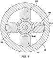
- Each end member also comprises an end laminate. As with the center laminate, the exemplary end laminates are segmented into teeth 134A, 134B, 136A, 136B ( FIG. 6 ), and 138A, 138B, 140A, 140B ( FIG. 4 ). Exemplary teeth geometry and attachments may be similar to those described above for the teeth of the center laminate.
- FIGS. 4 and 6 show respective portions 38-3 and 38-2 of the gap 38 at the end laminates.
- the exemplary rotor 22 comprises a metallic core 144 carrying a laminate 146 on its outer diameter (OD) surface.
- the exemplary laminate 146 is full-length for ease of manufacture. Portions of the laminate axially between the teeth may be essentially non-functional and could be replaced by monolithic steel or other filler material.
- FIG. 7 shows a schematic longitudinal sectional view centrally through diametrically opposed pair of the center teeth and coils of the bearing 20.
- four flux loops (paths) 550A, 550B, 552A, 552B are shown. These are shown schematically with a single line each rather than a plurality of lines each as in a contour map. Also, though one broken line path is shown through each laminate stack, it would be a distribution of flux across the laminate stack.
- the coils are not energized. Thus, fields in the upper half of the drawing are symmetric to those in the lower half.
- FIG. 7 thus shows how the radial polarity of the intermediate ring 60 augments the respective flux loops at the respective sides of the transverse centerplane.
- FIG. 8 shows the fields as modified by electromagnetic bias of the radial coils to exert an upward force on the rotor as viewed in FIG. 8 .
- the illustrated coils are energized in such a direction so that their associated magnetic flux augments the loops in the upper half of the sheet and counters the loops in the lower half.
- the exemplary magnitudes of applied currents are significant enough so that the net flux 550A', 552A' in the lower half is reversed in direction relative to that of FIG. 7 .
- the upper flux loops 550B', 552B' are schematically shown of increased flux by greater line weight than in FIG. 7 . The net effect of this is to apply a force to the rotor in the upward direction along the sheet.
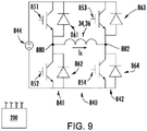
- FIG. 9 shows an H-bridge amplifier 840 used to power one or more coils. This may be controlled by or integrated with the controller 200.
- each H-bridge amplifier 840 has a single associated coil and vice-versa. This allows independent powering of the coils so that different current magnitudes may be applied to each.
- the amplifier 840 has two legs or branches 841 and 842 connected in parallel to a voltage source 844.
- the exemplary voltage source 844 is a constant DC voltage source and may be shared by the H-bridge amplifiers of the different coils.
- the terminals 880 and 882 of the coil are connected across central locations of the two legs 841 and 842. To each side (high voltage and low voltage) of each leg, the terminal 880, 882 is connected to the voltage source via the parallel combination of a respective switching device 851, 852, 853, 854 and diode 861, 862, 863, 864.
- Exemplary switching devices are gate controlled switching devices such as insulated gate bipolar transistors (IGBT) or metal oxide field effect transistors (MOSFET).
- IGBT insulated gate bipolar transistors
- MOSFET metal oxide field effect transistors
- the coils in a given pair may be in series powered by a single H-bridge amplifier so that the terminal 880 is one terminal of the first coil, the terminal 882 is one terminal of the second coil, and the other terminals of the coils are connected to each other.
- Alternative embodiments may have asymmetries between the coils of the two respective pairs or the two coils of a given pair. For example, it may be desirable to provide a baseline upward bias. Also, yet alternative embodiments may have configurations other than the two pairs (e.g., three coils and associated teeth at 120° intervals.
- FIG. 9 further shows a controller 200.
- the controller may be integrated with or provided by a controller of the turbomachine (e.g. electric compressor) as a whole or the system (e.g., refrigeration system).
- the controller may receive user inputs from an input device (e.g., switches, keyboard, or the like) and sensors (not shown, e.g., pressure sensors and temperature sensors at various system locations and, specifically for bearing control, radial position sensors (e.g., as shown in the WO '775 publication) and axial position sensors.
- the controller may be coupled to the sensors and controllable system components (e.g., valves, the bearings, the compressor motor, vane actuators, and the like) via control lines (e.g., hardwired or wireless communication paths).
- the controller may include one or more: processors; memory (e.g., for storing program information for execution by the processor to perform the operational methods and for storing data used or generated by the program(s)); and hardware interface devices (e.g., ports) for interfacing with input/output devices and controllable system components. Exemplary control is as disclosed in the WO '775 publication.
- FIG. 10 shows an alternative bearing 220 involving modifications to the stator 224.
- Rotor and control details may be the same as discussed regarding the bearing 20 of FIG. 1 .
- the one or more intermediate permanent magnets comprise a first ring 230 of one or more first intermediate magnets and a second ring 232 of one or more second intermediate magnets.
- the rings 230 and 232 have polarities (shown by arrows) substantially off-radial and off-axial to boost the respective flux loops at opposite sides of the transverse centerplane 510, 512 (e.g., between about 25° off-axial and about 65° off-axial, more narrowly, between about 35° off-axial and 55° off-axial).
- the exemplary rings 230 and 232 are shown with generally right triangular cross-section.
- the hypotenuse of the triangular section defines a frustoconical OD surface tapering in the directions shown (converging radially inward toward the transverse centerplane).
- other shapes are possible including rectangular cross-section and a convex line/surface replacing the hypotenuse of the triangle.
- the exemplary bearing also includes permanent magnet rings 240 and 242 axially outboard of the rings 50 and 52 with polarity similarly off-axial and radial to those of the rings 230 and 232 but so as to again augment the associated flux loops.
- the hypotenuse of the cross-section of each of the rings 240 and 242 forms a frustoconical surface radially diverging toward the transverse centerplane or radially converging away from the transverse centerplane.
- FIG. 10 also shows further manufacturing variation that could be used in the FIG. 1 implementation or other implementation.
- the stator includes a circumferential jacket or sleeve 250 (e.g., of steel or other metal) to facilitate mounting in the housing.
- the exemplary sleeve 250 is full annulus.
- an encapsulating material 252 e.g., a molded polymer optionally fiber-reinforced.
- the rotor 322 comprises one or more first permanent magnets 150 and one or more second permanent magnets 152, respectively, radially inboard of the stator permanent magnets 50 and 52 and of respective polarity substantially opposite thereto so as to cooperate with the respective associated stator magnets to define the permanent magnet flux loops associated with the permanent magnet bias discussed above.
- the exemplary rotor 322 comprises a metallic core 160 (e.g., of a magnetic steel) mounted to the shaft and carrying the stator permanent magnets in associated radially outwardly open channels.
- the support may be formed by turning of metallic rod stock on a lathe.
- end-to-end segments may combine to surround a full 360°.
- Such a configuration of two or more magnets allows assembly via radial inward insertion.
- the arrays may be contained by respective jackets 170, 172.
- Exemplary jackets are non-metallic composite wrapping (e.g., carbon fiber or fiberglass tape in epoxy matrix). Metallic jackets may be relevant to high speed applications.
- FIG. 11 also shows the rotor 322 as carrying a center laminate 178 and respective first and second end laminates 180 and 182. These rotor laminates are radially inboard of an axis aligned with the respective stator laminates and define the associated gap portions 38-1, 38-2, and 38-3 therewith.
- the exemplary core 160 thus has respective portions 162, 164, and 166 forming a rotor center back iron or yoke and first and second end back irons or yokes.
- the core 160 is multiple pieces. For example, one piece may form the center back iron and portions radially inboard of the rotor magnets and two respective pieces may form the rotor end yokes.
- Such a configuration may allow easy assembly of a system with full annulus rotor magnets and no separate retainers. Assembly may be via a series of shrink fits via heating and cooling.
- the inner diameter boundaries or faces of the rotor 322 laminates are radially outboard of the ID faces or boundaries of the rotor permanent magnets to ease turning of the flux fields.
- the added stator magnets provide an additional flux boost.
- this boost may allow use of non-rare earth magnets.
- Rare earth magnets are characterized by magnets with use rare earth elements such as dysprosium, terbium, europium, neodymium, samarium, and yttrium. Combined contents of those elements will typically be at least 10.0% by weight (e.g. 10.0% to 50.0%) or at least 20.0%.
- Neodymium is typically the key element in the main class of rare earth magnets (neodymium magnets), thus non-rare earth magnets may have under 10.0% by weight of this element in particular.
- samarium-cobalt magnets e.g. typically 15% to 45% samarium by weight
- samarium may also be below 15.0% or 10.0% by weight.
- Exemplary non-rare earth magnets are ferrite/ceramic magnets, alnico, manganese bismuth, iron nitride, and the like. However, other embodiments may use rare earth magnets or combinations.
- first, second, and the like in the description and following claims is for differentiation within the claim only and does not necessarily indicate relative or absolute importance or temporal order. Similarly, the identification in a claim of one element as “first” (or the like) does not preclude such "first” element from identifying an element that is referred to as “second” (or the like) in another claim or in the description.
Landscapes
- Engineering & Computer Science (AREA)
- General Engineering & Computer Science (AREA)
- Mechanical Engineering (AREA)
- Physics & Mathematics (AREA)
- Electromagnetism (AREA)
- Power Engineering (AREA)
- Magnetic Bearings And Hydrostatic Bearings (AREA)
Claims (15)
- Magnetlager (20; 220; 320), umfassend:einen Rotor (22; 322), der für Rotation um eine Achse (502) gestützt werden soll;einen Stator (24; 224), der sich von einem ersten Ende (30) zu einem zweiten Ende (32) erstreckt und Folgendes umfasst:einen oder mehrere erste Permanentmagnete (50);einen oder mehrere zweite Permanentmagnete (52), die axial von dem einen oder den mehreren ersten Permanentmagneten beabstandet sind;einen oder mehrere axial zwischen dem einen oder den mehreren ersten Permanentmagneten und dem einen oder den mehreren zweiten Permanentmagneten dazwischenliegende Permanentmagnete (60; 230, 232);eine Vielzahl von Laminatzähnen (64A, 64B, 66A, 66B) von dem einen oder den mehreren dazwischenliegenden Permanentmagneten radial nach innen; undeine Vielzahl von radialen Windungen (34A, 34B, 36A, 36B), die jeweils einen jeweiligen zugehörigen Zahn der Vielzahl von Zähnen umgeben.
- Magnetlager nach Anspruch 1, wobei der eine oder die mehreren ersten Permanentmagnete und der eine oder die mehreren zweiten Permanentmagnete Magnete nicht aus seltenen Erden sind;
wobei der eine oder die mehreren dazwischenliegenden Permanentmagnete vorzugweise Magnete nicht aus seltenen Erden sind. - Magnetlager nach Anspruch 1, wobei:der eine oder die mehreren zweiten Permanentmagnete eine Polarität aufweisen, die im Wesentlichen entgegengesetzt zu einer Polarität des einen oder der mehreren ersten Permanentmagnete ist; undder eine oder die mehreren dazwischenliegenden Permanentmagnete eine Polarität aufweisen, die im Wesentlichen quer zu den Polaritäten des einen oder der mehreren ersten Permanentmagnete und des einen oder der mehreren zweiten Permanentmagnete ist.
- Magnetlager nach Anspruch 1, wobei der eine oder die mehreren ersten Permanentmagnete und der eine oder die mehreren zweiten Permanentmagnete vollständig ringförmig sind;
wobei der eine oder die mehreren dazwischenliegenden Permanentmagnete vorzugweise vollständig ringförmig sind. - Magnetlager nach Anspruch 1, das nicht ein Drucklager ist.
- Magnetlager nach Anspruch 1, wobei der Stator weiter Folgendes umfasst:ein erstes Endjoch (120), das axial an dem einen oder den mehreren ersten Permanentmagneten anliegt; undein zweites Endjoch (122), das axial an dem einen oder den mehreren zweiten Permanentmagneten anliegt.
- Magnetlager nach Anspruch 6, wobei der Stator weiter Folgendes umfasst:ein erstes Endlaminat (134A, 134B, 136A, 136B), das von dem ersten Endjoch umgeben ist; undein zweites Endlaminat (13 8A, 138B, 140A, 140B), das von dem zweiten Endjoch umgeben ist.
- Magnetlager nach Anspruch 7, wobei der Rotor weiter Folgendes umfasst:einen oder mehrere dritte Permanentmagnete (150);einen oder mehrere vierte Permanentmagnete (152), die axial von dem einen oder den mehreren dritten Permanentmagneten beabstandet sind; undein Zentrumslaminat (178) axial zwischen dem einen oder den mehreren dritten Permanentmagneten und dem einen oder den mehreren vierten Permanentmagneten.
- Magnetlager nach Anspruch 8, wobei:das Zentrumslaminat eine Innendurchmesser-(ID)-Oberfläche radial außenbords von jeweiligen Innendurchmesser-(ID)-Oberflächen des einen oder der mehreren dritten Permanentmagnete und des einen oder der mehreren vierten Permanentmagnete aufweist; oderwobei der Rotor weiter Folgendes umfasst:ein erstes Endlaminat (180; 242), das axial an dem einen oder den mehreren dritten Permanentmagneten anliegt; undein zweites Endlaminat (182; 244), das axial an dem einen oder den mehreren vierten Permanentmagneten anliegt.
- Magnetlager nach Anspruch 1, wobei der eine oder die mehreren dazwischenliegenden Permanentmagnete Folgendes umfassen:
einen oder mehrere erste dazwischenliegende Magnete (230) und einen oder mehrere zweite dazwischenliegende Magnete (232), wobei:der eine oder die mehreren ersten dazwischenliegenden Magnete (230) zwischen dem einen oder den mehreren ersten Permanentmagneten (50) und dem einen oder den mehreren zweiten dazwischenliegenden Magneten (232) liegen;der eine oder die mehreren ersten dazwischenliegenden Magnete (230) Polaritäten aufweisen, die im Verhältnis zu den Polaritäten des einen oder der mehreren ersten Permanentmagnete (50) teilweise radial nach innen gerichtet sind; undder eine oder die mehreren zweiten dazwischenliegenden Magnete (232) Polaritäten aufweisen, die im Verhältnis zu den Polaritäten des einen oder der mehreren zweiten Permanentmagnete (52) teilweise radial nach innen gerichtet sind. - Verfahren zum Verwenden des Magnetlagers nach Anspruch 1, wobei das Verfahren umfasst, dass Strom fließt durch:
die Vielzahl von radialen Windungen, um:
radiale Position des Rotors zu steuern. - Verfahren nach Anspruch 11, wobei:
die Vielzahl von radialen Windungen ein diametral entgegengesetztes erstes Windungspaar und ein diametral entgegengesetztes zweites Windungspaar orthogonal zu dem ersten Windungspaar umfasst; wobei:
das erste und das zweite Windungspaar vorzugweise jeweils durch einen jeweiligen zugehörigen H-Brückenverstärker mit Strom gespeist werden. - Verfahren nach Anspruch 12, wobei:für jede Windung des ersten Windungspaars und des zweiten Windungspaars:ein erster Permanentmagnetflusspfad als Schleife durch die Windung, den einen oder die mehreren ersten Permanentmagnete und den einen oder die mehreren dazwischenliegenden Permanentmagnete durchgeht; undein zweiter Permanentmagnetflusspfad als Schleife durch die Windung, den einen oder die mehreren zweiten Permanentmagnete und den einen oder die mehreren dazwischenliegenden Permanentmagnete durchgeht; undder fließende Strom Folgendes umfasst:
Strom, der durch eine Windung des ersten Windungspaars fließt, um den zugehörigen ersten und zweiten Permanentmagnetflusspfad zu vergrößern, während Betriebsstrom durch die andere Windung des ersten Windungspaars fließt, um dem zugehörigen ersten und zweiten Permanentmagnetflusspfad entgegenzuwirken; wobei:der fließende Strom Folgendes umfasst:
Strom, der durch eine Windung des zweiten Windungspaars fließt, um den zugehörigen ersten und zweiten Permanentmagnetflusspfad zu vergrößern, während Strom durch die andere Windung des zweiten Windungspaars fließt, um dem zugehörigen ersten und zweiten Permanentmagnetflusspfad entgegenzuwirken. - Maschine, die ein Lager nach Anspruch 1 umfasst.
- Magnetlager nach Anspruch 8, wobei:das erste Endjoch nicht laminierter Magnetstahl ist; unddas zweite Endjoch nicht laminierter Magnetstahl ist.
Applications Claiming Priority (2)
| Application Number | Priority Date | Filing Date | Title |
|---|---|---|---|
| US201762480412P | 2017-04-01 | 2017-04-01 | |
| PCT/US2018/018624 WO2018182872A1 (en) | 2017-04-01 | 2018-02-19 | Magnetic radial bearing with flux boost |
Publications (2)
| Publication Number | Publication Date |
|---|---|
| EP3607216A1 EP3607216A1 (de) | 2020-02-12 |
| EP3607216B1 true EP3607216B1 (de) | 2022-10-26 |
Family
ID=61563480
Family Applications (1)
| Application Number | Title | Priority Date | Filing Date |
|---|---|---|---|
| EP18708800.0A Active EP3607216B1 (de) | 2017-04-01 | 2018-02-19 | Magnetisches radiallager mit flussverstärkung |
Country Status (4)
| Country | Link |
|---|---|
| US (1) | US11028877B2 (de) |
| EP (1) | EP3607216B1 (de) |
| CN (2) | CN114876953B (de) |
| WO (1) | WO2018182872A1 (de) |
Families Citing this family (8)
| Publication number | Priority date | Publication date | Assignee | Title |
|---|---|---|---|---|
| WO2018182891A1 (en) | 2017-04-01 | 2018-10-04 | Carrier Corporation | Magnetic radial bearing with flux boost |
| US11047421B2 (en) | 2017-04-01 | 2021-06-29 | Carrier Corporation | Magnetic radial bearing with flux boost |
| CN111628607B (zh) * | 2020-04-26 | 2021-12-17 | 哈尔滨工业大学 | 一种周向分块式径向混合支撑电磁轴承系统及控制方法 |
| DE102021107842A1 (de) * | 2021-03-29 | 2022-09-29 | Linz Center Of Mechatronics Gmbh | Kombiniertes axial/radial-magnetlager |
| CN113833759B (zh) * | 2021-10-14 | 2023-06-30 | 哈尔滨工业大学 | 非对称结构永磁径向磁轴承 |
| CN114198403B (zh) * | 2021-12-31 | 2023-02-07 | 淮阴工学院 | 一种五自由度混合磁轴承 |
| CN117489701B (zh) * | 2023-09-15 | 2024-06-11 | 淮阴工学院 | 一种混合励磁不对称四自由度磁轴承及其参数设计方法 |
| CN118564556B (zh) * | 2024-07-31 | 2024-10-29 | 山东天瑞重工有限公司 | 一种三自由度解耦磁轴承 |
Family Cites Families (101)
| Publication number | Priority date | Publication date | Assignee | Title |
|---|---|---|---|---|
| DE2420814C3 (de) * | 1974-04-30 | 1980-10-16 | Padana Ag, Zug (Schweiz) | Magnetlager mit einem Lagerelement zur Festlegung eines translatorischen Freiheitsgrades |
| US3958842A (en) | 1975-02-03 | 1976-05-25 | Hughes Aircraft Company | Radial magnetic bearing |
| US4196946A (en) | 1978-05-25 | 1980-04-08 | Westinghouse Electric Corp. | Temperature compensated magnetic bearing system for a watthour meter |
| US4285552A (en) | 1980-02-11 | 1981-08-25 | Sperry Corporation | Torquer apparatus for magnetically suspended members |
| DE3032938A1 (de) | 1980-09-02 | 1982-04-15 | Thyssen Edelstahlwerke AG, 4000 Düsseldorf | Dauermagnetisches radiallager |
| JPS5819844A (ja) | 1981-07-30 | 1983-02-05 | Toshiba Corp | 回転陽極x線管用磁気軸受装置 |
| JPS58184319A (ja) | 1982-04-20 | 1983-10-27 | Mitsubishi Electric Corp | 磁気軸受 |
| GB2120463B (en) | 1982-05-13 | 1985-12-11 | Racal Mesl Microwave | Improvements in and relating to rotary actuators |
| US4542311A (en) | 1983-12-27 | 1985-09-17 | North American Philips Corporation | Long linear stroke reciprocating electric machine |
| US4732353A (en) | 1985-11-07 | 1988-03-22 | The United States Of America As Represented By The Administrator Of The National Aeronautics And Space Administration | Three axis attitude control system |
| US4634191A (en) | 1985-11-21 | 1987-01-06 | The United States Of America As Represented By The Administrator Of The National Aeronautics & Space Administration | Radial and torsionally controlled magnetic bearing |
| US4891567A (en) | 1987-07-16 | 1990-01-02 | Minebea Co., Ltd. | Brushless DC motor having an outer rotor |
| US5216308A (en) | 1989-05-25 | 1993-06-01 | Avcon-Advanced Controls Technology, Inc. | Magnetic bearing structure providing radial, axial and moment load bearing support for a rotatable shaft |
| US5095237A (en) | 1990-03-20 | 1992-03-10 | Nova Corporation Of Alberta | Sectoral core for magnetic bearing |
| US5172021A (en) * | 1991-07-03 | 1992-12-15 | Fuji Xerox Co., Ltd. | Deflector motor with gas bearing and magnet thrust bearing |
| US5220232A (en) | 1991-09-03 | 1993-06-15 | Allied Signal Aerospace | Stacked magnet superconducting bearing |
| US5231336A (en) | 1992-01-03 | 1993-07-27 | Harman International Industries, Inc. | Actuator for active vibration control |
| US5179308A (en) | 1992-01-14 | 1993-01-12 | Charles Stark Draper Laboratory, Inc. | High-speed, low-loss antifriction bearing assembly |
| US5202598A (en) | 1992-03-26 | 1993-04-13 | Sundstrand Corporation | Back-up bearing for permanent magnet biased magnetic bearing |
| US5514924A (en) | 1992-04-30 | 1996-05-07 | AVCON--Advanced Control Technology, Inc. | Magnetic bearing providing radial and axial load support for a shaft |
| US5319273A (en) | 1992-10-26 | 1994-06-07 | Satcon Technology Corporation | Fixed gain electromagnetic actuator and electromagnetic bearing incorporating same |
| US5736800A (en) | 1994-10-18 | 1998-04-07 | Iannello; Victor | Light weight, high performance radial actuator for magnetic bearing systems |
| US5572079A (en) | 1994-12-21 | 1996-11-05 | Magnetic Bearing Technologies, Inc. | Magnetic bearing utilizing brushless generator |
| CA2258854C (en) | 1995-06-19 | 2007-11-20 | Robert R. Holcomb | Electromagnetic therapeutic treatment device and methods of using same |
| GB2303412B (en) | 1995-07-14 | 1999-08-11 | Glacier Metal Co Ltd | Electromagnetic bearing |
| WO1997007340A1 (de) | 1995-08-18 | 1997-02-27 | Sulzer Electronics Ag | Magnetische lagervorrichtung und verfahren zum betrieb derselben |
| US5767597A (en) | 1996-07-26 | 1998-06-16 | Satcon Technology Corp. | Electromagnetically biased homopolar magnetic bearing |
| FR2759434B1 (fr) | 1997-02-10 | 1999-05-07 | Aerospatiale | Palier magnetique rotatif a centrage actif le long de l'axe de rotation et a faible cout |
| JPH11101235A (ja) | 1997-07-30 | 1999-04-13 | Nippon Seiko Kk | 磁気軸受 |
| JPH11101233A (ja) | 1997-09-26 | 1999-04-13 | Nippon Seiko Kk | 磁気軸受装置 |
| EP0989656B1 (de) | 1998-09-24 | 2009-03-11 | Levitronix LLC | Permanentmagnetisch erregter elektrischer Drehantrieb |
| EP1063753B1 (de) | 1999-06-22 | 2009-07-22 | Levitronix LLC | Elektrischer Drehantrieb mit einem magnetisch gelagerten Rotor |
| JP2001041239A (ja) | 1999-07-28 | 2001-02-13 | Seiko Seiki Co Ltd | 磁気軸受装置 |
| JP2001224154A (ja) | 2000-02-10 | 2001-08-17 | Japan Science & Technology Corp | マルチポール磁気浮上回転方法およびその装置 |
| JP2001248639A (ja) | 2000-03-03 | 2001-09-14 | Koyo Seiko Co Ltd | 磁気軸受のステータユニット及び制御型磁気軸受 |
| US6359357B1 (en) | 2000-08-18 | 2002-03-19 | The United States Of America As Represented By The Administrator Of The National Aeronautics And Space Administration | Combination radial and thrust magnetic bearing |
| EP1325239B1 (de) | 2000-10-09 | 2004-04-14 | Siemens Aktiengesellschaft | Einrichtung mit rotor und magnetlager zur berührungslosen lagerung des rotors |
| FR2817088B1 (fr) | 2000-11-17 | 2003-02-21 | Mecanique Magnetique Sa | Machine tournante a butee axiale magnetique integrant une generatrice de courant |
| JP2002161918A (ja) | 2000-11-24 | 2002-06-07 | Nsk Ltd | 磁気軸受装置 |
| JP2002354767A (ja) | 2001-05-18 | 2002-12-06 | Sankyo Seiki Mfg Co Ltd | 磁気浮上電動機 |
| US6849960B2 (en) | 2001-08-22 | 2005-02-01 | High Tide Associates, Inc. | Mobile electrical power source |
| US6657344B2 (en) | 2001-09-05 | 2003-12-02 | The Regents Of The University Of California | Passive magnetic bearing for a horizontal shaft |
| US7078838B2 (en) | 2001-09-05 | 2006-07-18 | The Regents Of The University Of California | Passive magnetic bearing for a motor-generator |
| US6641378B2 (en) | 2001-11-13 | 2003-11-04 | William D. Davis | Pump with electrodynamically supported impeller |
| US6727617B2 (en) | 2002-02-20 | 2004-04-27 | Calnetix | Method and apparatus for providing three axis magnetic bearing having permanent magnets mounted on radial pole stack |
| US6873235B2 (en) | 2002-04-11 | 2005-03-29 | Magtube, Inc. | Shear force levitator and levitated ring energy storage device |
| US7126244B2 (en) | 2004-12-30 | 2006-10-24 | Rozlev Corp., Llc | Magnetic bearing assembly using repulsive magnetic forces |
| HUP0500973A2 (en) | 2005-10-25 | 2007-06-28 | Janos Oroszi | Magnetic bearing assembly |
| US7902706B2 (en) | 2006-08-18 | 2011-03-08 | Maglev Technologies, Llc | Rotational apparatus including a passive magnetic bearing |
| US7859144B1 (en) | 2006-08-31 | 2010-12-28 | Joseph Y Sahyoun | Low frequency electromagnetic motor to create or cancel a low frequency vibration |
| DE102006060047A1 (de) | 2006-12-19 | 2008-06-26 | Minebea Co., Ltd. | Elektrische Maschine mit Hybridlager |
| DE102006062420A1 (de) | 2006-12-27 | 2007-12-27 | Siemens Ag | Verfahren und Einrichtung zur Regelung eines Magnetlagers |
| US7598646B2 (en) | 2007-02-26 | 2009-10-06 | The Boeing Company | Electric motor with Halbach arrays |
| US7868510B2 (en) | 2007-03-30 | 2011-01-11 | Rittenhouse Norman P | High-efficiency wheel-motor utilizing molded magnetic flux channels with transverse-flux stator |
| KR100980565B1 (ko) * | 2007-10-18 | 2010-09-06 | 가부시키가이샤 이와키 | 자기부상모터 및 펌프 |
| FR2923877B1 (fr) | 2007-11-16 | 2010-04-09 | Thales Sa | Palier magnetique centreur a double etages |
| EP2234243A1 (de) | 2008-01-24 | 2010-09-29 | Tokyo University Of Science Educational Foundation Administrative Organization | Lagerungsloser motor |
| DE102008021587B3 (de) | 2008-04-30 | 2009-12-10 | Siemens Aktiengesellschaft | Magnetlager mit Permanentmagneten in Halbach-Anordnung und supraleitenden Magneten und Maschine mit derartigen Magnetlagern |
| GB0813033D0 (en) | 2008-07-16 | 2008-08-20 | Cummins Generator Technologies | Rotating electrical machine |
| EP2148104A1 (de) | 2008-07-21 | 2010-01-27 | Siemens Aktiengesellschaft | Magnetisches Radiallager sowie magnetisches Lagersystem mit Stromversorgung |
| WO2010042349A2 (en) | 2008-10-09 | 2010-04-15 | Calnetix, Inc. | High-aspect-ratio homopolar magnetic actuator |
| JP5233047B2 (ja) | 2008-11-19 | 2013-07-10 | 学校法人立命館 | 磁気軸受 |
| CN201307809Y (zh) | 2008-11-28 | 2009-09-09 | 江苏大学 | 五自由度交流磁轴承支承的高速电主轴系统 |
| JP5465249B2 (ja) | 2009-07-16 | 2014-04-09 | 国立大学法人茨城大学 | 磁気浮上制御装置およびハイブリッド型磁気軸受け |
| JP2011085223A (ja) | 2009-10-16 | 2011-04-28 | Hokkaido Univ | 3軸能動制御型磁気軸受及びこれを用いた回転機 |
| US8378543B2 (en) | 2009-11-02 | 2013-02-19 | Calnetix Technologies, L.L.C. | Generating electromagnetic forces in large air gaps |
| FR2954961B1 (fr) | 2010-01-05 | 2012-04-13 | Patricia Sardou | Paliers magnetique passif |
| US8796894B2 (en) | 2010-01-06 | 2014-08-05 | Calnetix Technologies, L.L.C. | Combination radial/axial electromagnetic actuator |
| US8847451B2 (en) | 2010-03-23 | 2014-09-30 | Calnetix Technologies, L.L.C. | Combination radial/axial electromagnetic actuator with an improved axial frequency response |
| CN201730962U (zh) | 2010-04-29 | 2011-02-02 | 苏州同心医疗器械有限公司 | 五自由度永磁偏置磁轴承 |
| CN201696492U (zh) | 2010-05-24 | 2011-01-05 | 山东科技大学 | 低功耗混合式磁轴承 |
| CA2810289A1 (en) * | 2010-09-17 | 2012-03-22 | Hoganas Ab (Publ) | Rotor for modulated pole machine |
| CN101979888B (zh) | 2010-10-06 | 2012-12-05 | 潘家烺 | 能与普通转轴轴承组合消除轴承承载力的永磁能悬浮轴承 |
| US8299669B2 (en) | 2010-10-18 | 2012-10-30 | Hamilton Sundstrand Corporation | Rim driven thruster having transverse flux motor |
| CN102042327B (zh) | 2010-12-29 | 2013-04-17 | 北京奇峰聚能科技有限公司 | 一种低功耗大承载力永磁偏置混合径向磁轴承 |
| US9667109B2 (en) | 2011-03-31 | 2017-05-30 | Abb Research Ltd. | Permanent magnet electrical machine rotors with stacked annular magnets and retainers and construction methods therefor |
| WO2012141932A2 (en) | 2011-04-13 | 2012-10-18 | Smith James S | Flux focusing arrangement for permanent magnets, methods of fabricating such arrangements, and machines including such arrangements |
| US8482174B2 (en) | 2011-05-26 | 2013-07-09 | Calnetix Technologies, Llc | Electromagnetic actuator |
| US9531236B2 (en) | 2011-06-02 | 2016-12-27 | Calnetix Technologies, Llc | Arrangement of axial and radial electromagnetic actuators |
| CN102808846B (zh) * | 2011-06-03 | 2016-02-17 | 唐建一 | 实用的磁力定位式磁悬浮轴承 |
| CN102305242B (zh) | 2011-08-15 | 2013-03-13 | 江苏大学 | 一种径向-轴向三自由度交直流混合磁轴承 |
| US9255495B2 (en) | 2011-08-24 | 2016-02-09 | Dresser-Rand Company | Magnetically-coupled damper for turbomachinery |
| EP2594477A1 (de) | 2011-11-18 | 2013-05-22 | Hamilton Sundstrand Corporation | Felgenbetriebenes Strahlruder mit Transversalflussmotoren |
| CN203962688U (zh) | 2011-12-20 | 2014-11-26 | 株式会社安川电机 | 磁力轴承 |
| JP5979747B2 (ja) | 2012-04-27 | 2016-08-31 | セイコー化工機株式会社 | 流体移送装置 |
| BE1020693A3 (nl) | 2012-05-16 | 2014-03-04 | Atlas Copco Aipower Nv | Magnetisch lager en werkwijze voor het monteren van een ferromagnetische structuur rond een kern van een magnetisch lager. |
| EP2677176B1 (de) | 2012-06-22 | 2018-12-19 | Skf Magnetic Mechatronics | Kompakter elektrischer Zentrifugalkompressor |
| WO2014007851A1 (en) | 2012-07-03 | 2014-01-09 | Abb Research Ltd. | Active magnetic bearing assembly and arrangement of magnets therefor |
| CN103671522B (zh) | 2012-09-12 | 2018-05-15 | 张玉宝 | 一种径轴向磁悬浮轴承 |
| CN103427538B (zh) | 2013-08-27 | 2015-10-21 | 三峡大学 | 飞轮电池磁悬浮支承装置 |
| CN103470630B (zh) | 2013-09-18 | 2016-06-22 | 北京航空航天大学 | 一种斥力型组合磁体径向被动磁轴承 |
| EP2886891A1 (de) | 2013-12-20 | 2015-06-24 | Universidad Carlos III de Madrid | Supraleitendes Hochleistungsmagnetlager mit Radialspalt |
| JP6327887B2 (ja) * | 2014-03-04 | 2018-05-23 | 国立大学法人東京工業大学 | 電動機および電動機システム |
| US20150330444A1 (en) | 2014-05-16 | 2015-11-19 | General Electric Company | Symmetrical electromagnetic actuator |
| CN104632890B (zh) | 2015-01-13 | 2017-04-12 | 北京航空航天大学 | 一种带阻尼线圈一体化结构的四自由度径向磁轴承 |
| US10767691B2 (en) | 2015-02-26 | 2020-09-08 | Carrier Corporation | Magnetic bearing |
| CN204572784U (zh) * | 2015-04-30 | 2015-08-19 | 南京艾凌节能技术有限公司 | 一种并联式永磁磁悬浮轴承 |
| CN204572787U (zh) * | 2015-04-30 | 2015-08-19 | 王向东 | 一种永磁磁悬浮装置 |
| EP3115103B1 (de) | 2015-07-06 | 2021-04-21 | Levitronix GmbH | Mischvorrichtung sowie einmalvorrichtung für eine mischvorrichtung |
| US11047421B2 (en) | 2017-04-01 | 2021-06-29 | Carrier Corporation | Magnetic radial bearing with flux boost |
| WO2018182891A1 (en) | 2017-04-01 | 2018-10-04 | Carrier Corporation | Magnetic radial bearing with flux boost |
-
2018
- 2018-02-19 US US16/489,843 patent/US11028877B2/en active Active
- 2018-02-19 EP EP18708800.0A patent/EP3607216B1/de active Active
- 2018-02-19 WO PCT/US2018/018624 patent/WO2018182872A1/en not_active Ceased
- 2018-02-19 CN CN202210503102.XA patent/CN114876953B/zh active Active
- 2018-02-19 CN CN201880022879.6A patent/CN110462234B/zh active Active
Also Published As
| Publication number | Publication date |
|---|---|
| CN110462234A (zh) | 2019-11-15 |
| US20200025246A1 (en) | 2020-01-23 |
| CN114876953B (zh) | 2024-05-10 |
| CN110462234B (zh) | 2022-05-31 |
| WO2018182872A1 (en) | 2018-10-04 |
| EP3607216A1 (de) | 2020-02-12 |
| US11028877B2 (en) | 2021-06-08 |
| CN114876953A (zh) | 2022-08-09 |
Similar Documents
| Publication | Publication Date | Title |
|---|---|---|
| EP3607216B1 (de) | Magnetisches radiallager mit flussverstärkung | |
| EP3607218B1 (de) | Magnetisches radiallager mit flussverstärkung | |
| EP3262310B1 (de) | Magnetlager | |
| US7830057B2 (en) | Transverse flux machine | |
| EP3607217B1 (de) | Radial magnetlager mit flussverstärker | |
| US9461511B2 (en) | Electric machine with permanently excited armature and associated permanently excited armature | |
| EP3507514B1 (de) | Magnetisches axiallager | |
| US20200067380A1 (en) | Electric machine having an axial electrodynamic bearing | |
| US10927892B2 (en) | Magnetic thrust bearing | |
| JP6933731B2 (ja) | 永久磁石オフセットシステム及び方法 | |
| US20110140559A1 (en) | Magnetic Bearing Device of a Rotor Shaft Against a Stator With Rotor Disc Elements, Which Engage Inside One Another, and Stator Disc Elements | |
| US20140009026A1 (en) | Synchronous machine with optimized excitation device fixed to the stator | |
| US20250317015A1 (en) | Electromagnetic rotating power machine | |
| CN120601651A (zh) | 磁悬浮装置和电磁旋转驱动器 | |
| CN120301113A (zh) | 具有复合屏蔽护套的定子永磁电机 |
Legal Events
| Date | Code | Title | Description |
|---|---|---|---|
| STAA | Information on the status of an ep patent application or granted ep patent |
Free format text: STATUS: UNKNOWN |
|
| STAA | Information on the status of an ep patent application or granted ep patent |
Free format text: STATUS: THE INTERNATIONAL PUBLICATION HAS BEEN MADE |
|
| PUAI | Public reference made under article 153(3) epc to a published international application that has entered the european phase |
Free format text: ORIGINAL CODE: 0009012 |
|
| STAA | Information on the status of an ep patent application or granted ep patent |
Free format text: STATUS: REQUEST FOR EXAMINATION WAS MADE |
|
| 17P | Request for examination filed |
Effective date: 20191028 |
|
| AK | Designated contracting states |
Kind code of ref document: A1 Designated state(s): AL AT BE BG CH CY CZ DE DK EE ES FI FR GB GR HR HU IE IS IT LI LT LU LV MC MK MT NL NO PL PT RO RS SE SI SK SM TR |
|
| AX | Request for extension of the european patent |
Extension state: BA ME |
|
| DAV | Request for validation of the european patent (deleted) | ||
| DAX | Request for extension of the european patent (deleted) | ||
| GRAP | Despatch of communication of intention to grant a patent |
Free format text: ORIGINAL CODE: EPIDOSNIGR1 |
|
| STAA | Information on the status of an ep patent application or granted ep patent |
Free format text: STATUS: GRANT OF PATENT IS INTENDED |
|
| INTG | Intention to grant announced |
Effective date: 20211220 |
|
| GRAJ | Information related to disapproval of communication of intention to grant by the applicant or resumption of examination proceedings by the epo deleted |
Free format text: ORIGINAL CODE: EPIDOSDIGR1 |
|
| STAA | Information on the status of an ep patent application or granted ep patent |
Free format text: STATUS: REQUEST FOR EXAMINATION WAS MADE |
|
| INTC | Intention to grant announced (deleted) | ||
| GRAP | Despatch of communication of intention to grant a patent |
Free format text: ORIGINAL CODE: EPIDOSNIGR1 |
|
| STAA | Information on the status of an ep patent application or granted ep patent |
Free format text: STATUS: GRANT OF PATENT IS INTENDED |
|
| INTG | Intention to grant announced |
Effective date: 20220609 |
|
| GRAS | Grant fee paid |
Free format text: ORIGINAL CODE: EPIDOSNIGR3 |
|
| GRAA | (expected) grant |
Free format text: ORIGINAL CODE: 0009210 |
|
| STAA | Information on the status of an ep patent application or granted ep patent |
Free format text: STATUS: THE PATENT HAS BEEN GRANTED |
|
| AK | Designated contracting states |
Kind code of ref document: B1 Designated state(s): AL AT BE BG CH CY CZ DE DK EE ES FI FR GB GR HR HU IE IS IT LI LT LU LV MC MK MT NL NO PL PT RO RS SE SI SK SM TR |
|
| REG | Reference to a national code |
Ref country code: GB Ref legal event code: FG4D |
|
| REG | Reference to a national code |
Ref country code: CH Ref legal event code: EP |
|
| REG | Reference to a national code |
Ref country code: AT Ref legal event code: REF Ref document number: 1527220 Country of ref document: AT Kind code of ref document: T Effective date: 20221115 |
|
| REG | Reference to a national code |
Ref country code: DE Ref legal event code: R096 Ref document number: 602018042212 Country of ref document: DE |
|
| REG | Reference to a national code |
Ref country code: IE Ref legal event code: FG4D |
|
| REG | Reference to a national code |
Ref country code: LT Ref legal event code: MG9D |
|
| REG | Reference to a national code |
Ref country code: NL Ref legal event code: MP Effective date: 20221026 |
|
| REG | Reference to a national code |
Ref country code: AT Ref legal event code: MK05 Ref document number: 1527220 Country of ref document: AT Kind code of ref document: T Effective date: 20221026 |
|
| PG25 | Lapsed in a contracting state [announced via postgrant information from national office to epo] |
Ref country code: NL Free format text: LAPSE BECAUSE OF FAILURE TO SUBMIT A TRANSLATION OF THE DESCRIPTION OR TO PAY THE FEE WITHIN THE PRESCRIBED TIME-LIMIT Effective date: 20221026 |
|
| PG25 | Lapsed in a contracting state [announced via postgrant information from national office to epo] |
Ref country code: SE Free format text: LAPSE BECAUSE OF FAILURE TO SUBMIT A TRANSLATION OF THE DESCRIPTION OR TO PAY THE FEE WITHIN THE PRESCRIBED TIME-LIMIT Effective date: 20221026 Ref country code: PT Free format text: LAPSE BECAUSE OF FAILURE TO SUBMIT A TRANSLATION OF THE DESCRIPTION OR TO PAY THE FEE WITHIN THE PRESCRIBED TIME-LIMIT Effective date: 20230227 Ref country code: NO Free format text: LAPSE BECAUSE OF FAILURE TO SUBMIT A TRANSLATION OF THE DESCRIPTION OR TO PAY THE FEE WITHIN THE PRESCRIBED TIME-LIMIT Effective date: 20230126 Ref country code: LT Free format text: LAPSE BECAUSE OF FAILURE TO SUBMIT A TRANSLATION OF THE DESCRIPTION OR TO PAY THE FEE WITHIN THE PRESCRIBED TIME-LIMIT Effective date: 20221026 Ref country code: FI Free format text: LAPSE BECAUSE OF FAILURE TO SUBMIT A TRANSLATION OF THE DESCRIPTION OR TO PAY THE FEE WITHIN THE PRESCRIBED TIME-LIMIT Effective date: 20221026 Ref country code: ES Free format text: LAPSE BECAUSE OF FAILURE TO SUBMIT A TRANSLATION OF THE DESCRIPTION OR TO PAY THE FEE WITHIN THE PRESCRIBED TIME-LIMIT Effective date: 20221026 Ref country code: AT Free format text: LAPSE BECAUSE OF FAILURE TO SUBMIT A TRANSLATION OF THE DESCRIPTION OR TO PAY THE FEE WITHIN THE PRESCRIBED TIME-LIMIT Effective date: 20221026 |
|
| PG25 | Lapsed in a contracting state [announced via postgrant information from national office to epo] |
Ref country code: RS Free format text: LAPSE BECAUSE OF FAILURE TO SUBMIT A TRANSLATION OF THE DESCRIPTION OR TO PAY THE FEE WITHIN THE PRESCRIBED TIME-LIMIT Effective date: 20221026 Ref country code: PL Free format text: LAPSE BECAUSE OF FAILURE TO SUBMIT A TRANSLATION OF THE DESCRIPTION OR TO PAY THE FEE WITHIN THE PRESCRIBED TIME-LIMIT Effective date: 20221026 Ref country code: LV Free format text: LAPSE BECAUSE OF FAILURE TO SUBMIT A TRANSLATION OF THE DESCRIPTION OR TO PAY THE FEE WITHIN THE PRESCRIBED TIME-LIMIT Effective date: 20221026 Ref country code: IS Free format text: LAPSE BECAUSE OF FAILURE TO SUBMIT A TRANSLATION OF THE DESCRIPTION OR TO PAY THE FEE WITHIN THE PRESCRIBED TIME-LIMIT Effective date: 20230226 Ref country code: HR Free format text: LAPSE BECAUSE OF FAILURE TO SUBMIT A TRANSLATION OF THE DESCRIPTION OR TO PAY THE FEE WITHIN THE PRESCRIBED TIME-LIMIT Effective date: 20221026 Ref country code: GR Free format text: LAPSE BECAUSE OF FAILURE TO SUBMIT A TRANSLATION OF THE DESCRIPTION OR TO PAY THE FEE WITHIN THE PRESCRIBED TIME-LIMIT Effective date: 20230127 |
|
| REG | Reference to a national code |
Ref country code: DE Ref legal event code: R097 Ref document number: 602018042212 Country of ref document: DE |
|
| PG25 | Lapsed in a contracting state [announced via postgrant information from national office to epo] |
Ref country code: SM Free format text: LAPSE BECAUSE OF FAILURE TO SUBMIT A TRANSLATION OF THE DESCRIPTION OR TO PAY THE FEE WITHIN THE PRESCRIBED TIME-LIMIT Effective date: 20221026 Ref country code: RO Free format text: LAPSE BECAUSE OF FAILURE TO SUBMIT A TRANSLATION OF THE DESCRIPTION OR TO PAY THE FEE WITHIN THE PRESCRIBED TIME-LIMIT Effective date: 20221026 Ref country code: EE Free format text: LAPSE BECAUSE OF FAILURE TO SUBMIT A TRANSLATION OF THE DESCRIPTION OR TO PAY THE FEE WITHIN THE PRESCRIBED TIME-LIMIT Effective date: 20221026 Ref country code: DK Free format text: LAPSE BECAUSE OF FAILURE TO SUBMIT A TRANSLATION OF THE DESCRIPTION OR TO PAY THE FEE WITHIN THE PRESCRIBED TIME-LIMIT Effective date: 20221026 Ref country code: CZ Free format text: LAPSE BECAUSE OF FAILURE TO SUBMIT A TRANSLATION OF THE DESCRIPTION OR TO PAY THE FEE WITHIN THE PRESCRIBED TIME-LIMIT Effective date: 20221026 |
|
| PG25 | Lapsed in a contracting state [announced via postgrant information from national office to epo] |
Ref country code: SK Free format text: LAPSE BECAUSE OF FAILURE TO SUBMIT A TRANSLATION OF THE DESCRIPTION OR TO PAY THE FEE WITHIN THE PRESCRIBED TIME-LIMIT Effective date: 20221026 Ref country code: AL Free format text: LAPSE BECAUSE OF FAILURE TO SUBMIT A TRANSLATION OF THE DESCRIPTION OR TO PAY THE FEE WITHIN THE PRESCRIBED TIME-LIMIT Effective date: 20221026 |
|
| PLBE | No opposition filed within time limit |
Free format text: ORIGINAL CODE: 0009261 |
|
| STAA | Information on the status of an ep patent application or granted ep patent |
Free format text: STATUS: NO OPPOSITION FILED WITHIN TIME LIMIT |
|
| PG25 | Lapsed in a contracting state [announced via postgrant information from national office to epo] |
Ref country code: MC Free format text: LAPSE BECAUSE OF FAILURE TO SUBMIT A TRANSLATION OF THE DESCRIPTION OR TO PAY THE FEE WITHIN THE PRESCRIBED TIME-LIMIT Effective date: 20221026 |
|
| REG | Reference to a national code |
Ref country code: CH Ref legal event code: PL |
|
| 26N | No opposition filed |
Effective date: 20230727 |
|
| REG | Reference to a national code |
Ref country code: BE Ref legal event code: MM Effective date: 20230228 |
|
| GBPC | Gb: european patent ceased through non-payment of renewal fee |
Effective date: 20230219 |
|
| PG25 | Lapsed in a contracting state [announced via postgrant information from national office to epo] |
Ref country code: LU Free format text: LAPSE BECAUSE OF NON-PAYMENT OF DUE FEES Effective date: 20230219 Ref country code: LI Free format text: LAPSE BECAUSE OF NON-PAYMENT OF DUE FEES Effective date: 20230228 Ref country code: CH Free format text: LAPSE BECAUSE OF NON-PAYMENT OF DUE FEES Effective date: 20230228 |
|
| PG25 | Lapsed in a contracting state [announced via postgrant information from national office to epo] |
Ref country code: SI Free format text: LAPSE BECAUSE OF FAILURE TO SUBMIT A TRANSLATION OF THE DESCRIPTION OR TO PAY THE FEE WITHIN THE PRESCRIBED TIME-LIMIT Effective date: 20221026 |
|
| REG | Reference to a national code |
Ref country code: IE Ref legal event code: MM4A |
|
| PG25 | Lapsed in a contracting state [announced via postgrant information from national office to epo] |
Ref country code: GB Free format text: LAPSE BECAUSE OF NON-PAYMENT OF DUE FEES Effective date: 20230219 |
|
| PG25 | Lapsed in a contracting state [announced via postgrant information from national office to epo] |
Ref country code: IE Free format text: LAPSE BECAUSE OF NON-PAYMENT OF DUE FEES Effective date: 20230219 Ref country code: GB Free format text: LAPSE BECAUSE OF NON-PAYMENT OF DUE FEES Effective date: 20230219 |
|
| P01 | Opt-out of the competence of the unified patent court (upc) registered |
Effective date: 20240119 |
|
| PG25 | Lapsed in a contracting state [announced via postgrant information from national office to epo] |
Ref country code: BE Free format text: LAPSE BECAUSE OF NON-PAYMENT OF DUE FEES Effective date: 20230228 |
|
| PG25 | Lapsed in a contracting state [announced via postgrant information from national office to epo] |
Ref country code: IT Free format text: LAPSE BECAUSE OF FAILURE TO SUBMIT A TRANSLATION OF THE DESCRIPTION OR TO PAY THE FEE WITHIN THE PRESCRIBED TIME-LIMIT Effective date: 20221026 |
|
| PG25 | Lapsed in a contracting state [announced via postgrant information from national office to epo] |
Ref country code: BG Free format text: LAPSE BECAUSE OF FAILURE TO SUBMIT A TRANSLATION OF THE DESCRIPTION OR TO PAY THE FEE WITHIN THE PRESCRIBED TIME-LIMIT Effective date: 20221026 |
|
| PG25 | Lapsed in a contracting state [announced via postgrant information from national office to epo] |
Ref country code: BG Free format text: LAPSE BECAUSE OF FAILURE TO SUBMIT A TRANSLATION OF THE DESCRIPTION OR TO PAY THE FEE WITHIN THE PRESCRIBED TIME-LIMIT Effective date: 20221026 |
|
| PG25 | Lapsed in a contracting state [announced via postgrant information from national office to epo] |
Ref country code: CY Free format text: LAPSE BECAUSE OF FAILURE TO SUBMIT A TRANSLATION OF THE DESCRIPTION OR TO PAY THE FEE WITHIN THE PRESCRIBED TIME-LIMIT; INVALID AB INITIO Effective date: 20180219 |
|
| PG25 | Lapsed in a contracting state [announced via postgrant information from national office to epo] |
Ref country code: HU Free format text: LAPSE BECAUSE OF FAILURE TO SUBMIT A TRANSLATION OF THE DESCRIPTION OR TO PAY THE FEE WITHIN THE PRESCRIBED TIME-LIMIT; INVALID AB INITIO Effective date: 20180219 |
|
| PG25 | Lapsed in a contracting state [announced via postgrant information from national office to epo] |
Ref country code: TR Free format text: LAPSE BECAUSE OF FAILURE TO SUBMIT A TRANSLATION OF THE DESCRIPTION OR TO PAY THE FEE WITHIN THE PRESCRIBED TIME-LIMIT Effective date: 20221026 |
|
| PGFP | Annual fee paid to national office [announced via postgrant information from national office to epo] |
Ref country code: DE Payment date: 20260121 Year of fee payment: 9 |
|
| PGFP | Annual fee paid to national office [announced via postgrant information from national office to epo] |
Ref country code: FR Payment date: 20260121 Year of fee payment: 9 |