EP3608065A1 - Dispositif de stockage pour outils - Google Patents
Dispositif de stockage pour outils Download PDFInfo
- Publication number
- EP3608065A1 EP3608065A1 EP19197524.2A EP19197524A EP3608065A1 EP 3608065 A1 EP3608065 A1 EP 3608065A1 EP 19197524 A EP19197524 A EP 19197524A EP 3608065 A1 EP3608065 A1 EP 3608065A1
- Authority
- EP
- European Patent Office
- Prior art keywords
- tools
- base body
- surface sections
- surface section
- flat
- Prior art date
- Legal status (The legal status is an assumption and is not a legal conclusion. Google has not performed a legal analysis and makes no representation as to the accuracy of the status listed.)
- Granted
Links
Images






Classifications
-
- B—PERFORMING OPERATIONS; TRANSPORTING
- B25—HAND TOOLS; PORTABLE POWER-DRIVEN TOOLS; MANIPULATORS
- B25H—WORKSHOP EQUIPMENT, e.g. FOR MARKING-OUT WORK; STORAGE MEANS FOR WORKSHOPS
- B25H3/00—Storage means or arrangements for workshops facilitating access to, or handling of, work tools or instruments
- B25H3/02—Boxes
-
- B—PERFORMING OPERATIONS; TRANSPORTING
- B25—HAND TOOLS; PORTABLE POWER-DRIVEN TOOLS; MANIPULATORS
- B25H—WORKSHOP EQUIPMENT, e.g. FOR MARKING-OUT WORK; STORAGE MEANS FOR WORKSHOPS
- B25H3/00—Storage means or arrangements for workshops facilitating access to, or handling of, work tools or instruments
- B25H3/003—Holders for drill bits or the like
Definitions
- the invention relates to a device for storing tools.
- Devices for storing tools are known from the DE 102 52 747 A1 , the DE 10 2011 054 219 , the DE 20 2009 012 145 U1 , from the DE 10 2005 061 185 A1 ,
- Bags made of textile material are known in particular, which can be brought into a storage position by rolling them up from a removal position, in which the flat base body is spread out in one plane.
- the invention has for its object to develop a known tool bag user-friendly.
- the device according to the invention has a flat base body which has an inside and an outside. Holding devices are provided on the inside for restraining the tools to the base body.
- the base body is divided into surface sections by several hinges.
- the surface sections can be folded into a storage position around the hinges formed by fold lines. In the safekeeping position, the surface sections complement each other to form an outer surface of a solid.
- a polygonal solid is formed with several, for example two broad side surfaces, two narrow side surfaces and two end surfaces. The end faces can run parallel to each other, so that the polygonal solid body Has the shape of a prism.
- the surface sections of the base body can each form a dimensionally stable and flexible flat body.
- At least the outer surface can consist of a textile material, so that the device is haptically appealing. It is preferably a soft textile, so that the closed or opened device can also be placed on sensitive surfaces, for example the bodies of motor vehicles.
- the surface sections connected to one another in a hinge-like manner cannot be placed only on a flat base surface. They can also be placed on an open space, for example a curved surface. In the removal position, the individual surface sections which are connected to one another in an articulated manner can nestle like armored chains on the surface contour of the base.
- the rigidity of the walls is determined in particular by the rigidity of plastic insert plates, which are preferably sewn in between two textile layers.
- the two textile layers can be directly connected to one another along the hinges, for example with a seam.
- the insert plates can be magnetically equipped so that the opened device is held on a steel base with magnetic force.
- the magnetic equipment of the insert plates can also be used to fix the device in its closed position.
- the end faces of the polygonal solid can be closed by tabs which are attached to the base body.
- the edge of the end face can be formed by the outer edge of a hem.
- the base body can be placed in its storage position on this edge formed by the hem.
- An end face can also be formed by several tabs.
- the multiple tabs then complement each other to form an essentially flat end face.
- the tools are fastened to the inside of the surface sections with holding devices, for example made of plastic. Gaps remain next to a tool.
- the Tools can be gripped by the user.
- the gaps are preferably large enough to accommodate fingertips.
- sections of tools reach into these gaps, which are assigned to other in particular adjacent or in the custody position opposite surface sections.
- the arrangement of the tools is selected such that the gaps between or next to the tools are filled or at least partially filled in the safekeeping of sections of other tools. If the device, which is preferably designed as a tool pocket, is closed, tools from adjacent or opposite pocket sides engage in the gaps in order to largely fill them. It is considered an advantage that the tools are arranged with the greatest possible overview in the open state, but the bag has a minimal pack size when closed.
- the broad side surface sections carry holding devices which are at a distance from the fold lines.
- the tools fastened to the narrow surface sections can have a width which essentially corresponds to the distance dimension of the inner sides of the wide surface sections opposite one another in the storage position.
- a ratchet can be attached to a narrow surface section, the ratchet head of which is only slightly narrower than the width of the wide surface section.
- Nuts can be attached to the inside of the opposite narrow surface section. Each nut sits on an associated holder, which can be made of plastic. The nut with the largest width across flats has a diameter that is only slightly less than the width of the narrow section.
- elongated tools such as shaft extension pieces for a ratchet or the ratchet itself, are parallel are arranged to the crease lines.
- Shorter tools for example bits or nuts, are arranged with their axes transverse to the direction of extension of the fold lines.
- the device according to the invention is in particular a textile tool bag which consists of two layers of textile which are sewn together along the fold line. The peripheral edge of the two layers of fabric is closed using a hem tape. The tabs forming the end faces are fastened to one of the wide area sections by means of the hem band.
- the stiffening elements which are preferably made of plastic and are formed by flat bodies, lie in the spaces between the textile layers, which are separated from one another by seams and in particular the seams forming the fold lines.
- the holders can be made of textile or plastic loops, in particular made of soft or hard plastic, into which the tools can be inserted. It is particularly advantageous if the insert plates or a plurality of sections of a uniform insert plate are connected to one another via spring bars which, in the untensioned state, hold the insert plates or their sections in one plane.
- the webs are bent when the tool bag is closed, in particular bent by 90 °. They then deliver a spring force that causes the tool bag to open automatically when its closure is opened.
- the tool bag has an insert body that stiffens at least two, preferably all, surface sections.
- the flat body has slots in the area of the hinges. The area between a slot and the outer edge then forms a spring bar.
- the insert body can be a flat body which consists of a resilient plastic material which has a plurality of slots which run parallel to one another and are spatially assigned to the hinges.
- the flat body which is pocketed in a textile jacket, forms webs / bridges at the areas adjoining the slots out.
- the textile layers are connected to one another by means of seams, seams running through the slots.
- the invention relates to a further development of the storage device for tools described above, in which the tools are screwdriver bits, in particular screwdriver bits, which have an axial length of 25 mm and a 1 ⁇ 4 "hexagon section with which the bits are inserted into the insertion openings of holders It is provided that at least two surface sections each have one or more holding devices.
- the holding devices can consist of plastic and can be connected, for example glued, to the inner surfaces of the storage device.
- Each of the holding devices has a plurality of straight rows spaced apart from one another by space, each having a plurality The rows of holding devices which are different from one another are offset from one another in such a way that when the device is closed in the safekeeping position, those in the insertion opening Immerse the openings of the screwdriver bits that insert one holding device into the clearances of the other holding device.
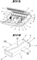
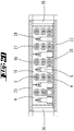
- the exemplary embodiment is a device for storing tools, in particular screwing tools 5, 7, 9, 11, 13. It has a flat base body 1 which has an inside 2 and an outside 3. The inside 2 is formed by a first textile layer and the outside 3 by a second textile layer. On the inside 2 holding devices 4, 6, 8, 10, 12 are provided for capturing the tools 5, 7, 9, 11, 13, with which the tools 5, 7, 9, 11, 13 are attached to the base body 1.
- the base body 1 is divided by a plurality of hinges 14, 15, 16, 17 into a plurality of surface sections 18, 19, 20, 21, 22.
- the surface sections can from a tool removal position, as in the Figure 1 is shown, in which the surface sections 18, 19, 20, 21, 22 lie essentially in one plane, around which the hinges 14, 15, 16, 17 formed by folding lines are folded into a storage position, which is shown in FIG Figure 6 is shown.
- the tools 5, 7, 9, 11, 13 are not visible in the storage position.
- Two surface sections 22, 18 overlap in regions and are tied to one another with fastening elements (not shown), for example with a push button, with a Velcro fastener or with a magnet.
- the textile tool bag has the shape of a polygonal solid.
- the polygonal solid forms a cuboid.
- the end faces of the cuboid are formed by tabs 26 which, according to a hem 31, are arranged to spring back somewhat in relation to the edge edge of the base body 1.
- the stiffness of the individual surface sections is guaranteed by pocketed flat bodies.
- the flat bodies are insert bodies with a rectangular cut, the insert bodies being made of plastic.
- the flexibility of the base body in the area of the hinge lines 14, 15, 16, 17 is achieved in that the two textile layers are sewn directly to one another there. In the Figures 1 to 11 this type of connection is not recognizable, but can be seen in the sectional view of Figure 12 ,
- the arrangement of the tools within the device is selected such that the tools 5, 7, 9, 11, 13 are arranged in the open state with the greatest possible overview, but the bag takes up a minimum packing size in the closed state.
- the bag takes up a minimum packing size in the closed state.
- in the open state there is sufficient space next to the tools and in particular on opposite sides of the tool so that a user can hold the tool there between two fingers. This clearance, which can be used for removal and loading, is filled by another tool when closed.
- a holding device 10 On a wide area section 20 there is a holding device 10 which forms two loops. In one of the loops there is a long extension shaft for a ratchet. In the other loop there is a shorter extension shaft for a ratchet. In a further loop 8 there is a chuck 9 into which a bit 5 can be inserted. The axes of the shafts 11, 11 'and of the chuck 9 run parallel to the hinge lines 14, 15, 16, 17. There is a free space 27 between the shaft 11 and the fold line 16. On the opposite side of the shaft 11 there is a further clearance space 28 between the shaft 11 and the hinge line 15. Rectangular tabs 26 are on the two opposite free edge edges of the wide area section 20 sewn on.
- the narrow surface section 21 connected to the wide surface section 20 via the hinge line 16 carries a ratchet 13, the ratchet head of which has a width which is only slightly less than the width of the narrow surface section 21.
- the arm of the ratchet 13 is located in two loops 12 and has an axial extension which extends parallel to the hinge lines 14, 15, 16, 17. If the narrow surface section 21 of the in the Figure 1 shown in the open position in the Figure 4 brought position shown, that is, set up about the hinge line 16 by 90 °, the head of the ratchet 13 pivots into the clearance 27 next to the shaft 11th
- the narrow surface section 19 adjoining the wide surface section 20 via the hinge line 15 carries a large number, namely nine nuts 7 each having a different wrench size.
- Plastic push-on holders 6 are connected to the inside of the narrow surface section 19, onto which the nuts 7 are fitted such that their axes extend transversely to the direction of extension of the hinge lines 14, 15, 16, 17. If the narrow surface section 19 of the in Figure 1 shown in the open position in Figure 5 Position shown pivoted up 90 °, the nuts 7 attached to the narrow surface section 19 are pivoted into the clearance 28 next to the shaft 11.
- the narrow surface section 19 is connected to a wide surface section 18 via the hinge 14.
- the wide area section 18 carries screwdriver bits 5.
- Each screwdriver bit 5 is in a holder 4.
- the holder 4 is formed by a loop.
- a loop body forms several loops.
- the loops form cavities which extend in a direction transverse to the hinge lines 14, 15, 16, 17.
- the polygonal sections, not shown, of the screwdriver bits 15 are in the loops 4, so that the working tips of the bits 5 protrude from the loops. There is free space between the individual working tips so that the bits can be picked up between two fingers.
- a clearance space 29 extends between the holder 4 and the hinge line 14. If the narrow area section 19 is brought into a 90 ° position relative to the wide area section 18, the nuts 7 pivot into the clearance space 29. In the closed state, the clearance space 28 lies between the clearance space 29 across from.
- plug-on brackets 6 project transversely to the surface extension of the inside 3 when the device is open. This enables simple loading and unloading of the nuts.
- the closure flap connected to the narrow surface section 21 via the hinge line 17 is likewise formed by a surface section 22. In the closed state, the surface section 22 overlaps the surface section 18.
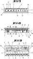
- the Figures 13 and 14 show a second embodiment that differs from that in the Figures 1 to 12 illustrated embodiment essentially differs only by the insert body 23.
- the insert body is in the plan view in the Figure 14 shown. It consists of a single flat body made of a flexible plastic.
- the flat body 23 has four slots 32 running parallel to one another.
- the flat body 23 is inserted between two textile layers.
- the textile layers are connected to one another with seams, the seams running through the slots 32.
- the slots 32 fall together with the hinge lines 14, 15, 16, 17.
- the slots 32 are enclosed all around and have a narrow floor plan.
- the two longitudinal edges run parallel to each other.
- Webs 33 are formed between each narrow edge of the slot 32 and the outline contour of the flat body 32. These material webs form spring webs.
- the spring bars 33 are bent by 90 °. Their spring tension means that the tool bag automatically moves into the Figure 13 shown position opens when the shutter is opened.
- the material of the insert body 23 can be a fiber-reinforced plastic, for example a glass-fiber reinforced plastic.
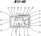
- the Figures 15 and 16 show a third embodiment of the invention, in which the storage device in the open position has a flat base body, which consists of surface sections 18, 19, 20, 21, 22 connected with hinge lines 14, 15, 16, 17.
- the surface sections 18, 20 and 21 are equipped with tools.
- the narrow surface section 21 has a fastening tab 21 which holds a screwdriver handle 31 with an insert chuck.
- the wide area section 20 has two brackets 4 arranged parallel to the hinge lines 15, 16 for receiving bits 5.
- the brackets 4 are plastic bodies m with insertion openings for one bit 5 each.
- the brackets 4 are flat with the inside of the area section 20 connected, which also carries two tabs 26 which close the narrow sides in the closed position.
- a clearance 27 is formed in the area of the hinge 16, into which the screwing tool 13 can pivot in the closed state.
- the insertion openings of the holding device 4 for the individual bits 5 are arranged one behind the other as a row.
- a space 28 remains between the two rows, in the closed state of which a row of bits engages, which is arranged on the surface section 18.
- the surface section 18 carries a holding device 4 with insertion openings for bits 5.
- the surface section 18 carries only a single row of bits. In addition to the row there are clearance spaces 27, 29 into which the bits seated on the surface section 20 can pivot in the folded state.
- a narrow side wall 21 carries a lining 13 which is fastened to the narrow side wall by means of a loop 12.
- This storage device also has surface sections 18, 19, 20, 21, 22 which abut on parallel hinge lines 14, 15, 16, 17.
- Two wide-area sections 18, 20 lying opposite one another in the closed position are each equipped with holders 4 made of plastic for receiving bits.
- the brackets 4 each have insertion openings for one bit.
- the insertion openings are arranged as rows running transversely to the hinge lines 14, 15, 16. The rows are spaced apart from one another in such a way that clearance spaces 27, 28 form between the rows.
- the outer edges of the surface section 20 each carry a tab 26, which form a side wall of the cuboid storage device in the closed state.
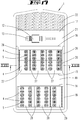
- the fifth exemplary embodiment shown is, like all other exemplary embodiments, a screwing tool storage device with a flat body when open.
- the base body has a textile outside and preferably also a textile inside.
- the screwing tool 13 is fastened here to a narrow side surface 21 by means of a loop 12.
- the opposite narrow side surface 19 carries a holder 4 for screwdriver bits.
- the screwdriver bits are arranged in a number of rows which extend transversely to the alignment of the hinge axes 14, 15. Each insertion opening has three bit openings.
- a chuck 9 is inserted in a receiving opening.
- the broad side surface 20 is equipped on its inside with two holding devices 4 running parallel to the hinge lines 14, 15.
- Each of the two holding devices running parallel to one another has a plurality of rows of insertion openings, each for a bit 5.
- each row contains three insertion openings, with a total of six insertion openings lying one behind the other in a direction transverse to the course of the hinge lines 14.
- the rows are single-row, so that each bit has a maximum of two neighbors.
- the in the Figures 15 to 20 The storage devices shown have a total of five surface sections 18 to 22. When closed, the surface sections 18, 22 lie in touching contact, to a certain extent parallel to one another.
- the surface section 22 is provided with adhesives which can adhere to the outside of the surface section 18 when the device is closed.
- tabs 26 are assigned to the surface section 20, which has at least one or more holding devices 4 for bits 5 or holding devices 4 equipped with bits 5, which in the closed state form opposite walls of the storage device, the tabs 26 are particularly flexibly attached to the edges of the surface section 20, for example sewn or glued.
- a chuck 9 or an extension piece is inserted into an insertion opening of a holder 4 assigned to a narrow surface section 19, which in the closed state of the storage device between two row-shaped holding sections of the Holding device 4 is located, which are assigned to the wide surface section 20, which adjoins the narrow surface section 19 directly on a hinge line 15.
- holders 4 assigned to a first surface section 20 have rows of insertion openings for bits 5 spaced apart from one another and another surface section 18, 19 of identical construction has holders 4 for bits 5 whose insertion openings for bits 5 arranged in a row are offset in such a way as to the rows arranged insertion openings of the holder 4 of the surface section 20 are arranged in such a way that the bits inserted in the insertion openings of the respective holding device 4 dip into the clearance spaces 27, 28 of the respective other holding device 4.
- a device for storing tools, in particular screwing tools, with a flat base body 1, which has an inside 2 and an outside 3, 2 holding devices 4, 6, 8, 10, 12 on the inside for capturing the tools 5, 7, 9, 11, 13 are provided on the base body 1, the base body 1 being divided into surface sections 18, 19, 20, 21, 22 by a plurality of hinges 14, 15, 16, 17, which surface sections 18, 19, 20, 21, 22 of a tool removal position, in which the surface sections 18, 19, 20, 21, 22 lie essentially in one plane, around which the hinges 14, 15, 16, 17 can be folded into a storage position, in which the outer sides 3 of the surface sections 18, 19, 20, 21, 22 form flat surfaces of a polygonal solid.
- a device which is characterized in that the surface sections 18, 19, 20, 21, 22 of the base body are each stiffened by a dimensionally stable and flexible flat body / flat body section 23 and in particular at least the outside 3 of a surface section 18, 19, 20, 21, 22 is formed from a textile material.
- a device which is characterized in that the device has the shape of a prism in its storage position and has such a rigidity that the device is stable with each of its surface sections 18, 19, 20, 21, 22 and / or with its mutually facing and end faces 24, 25 running parallel to one another can be set up on a flat base surface.
- a device which is characterized in that the holding devices 4, 6, 8, 10, 12 are arranged in such a way that the tools 5, 7, 9, 11, 13 fastened to the base body 1 thereby stiffen the base body 1 in its storage position.
- a device which is characterized in that the inside 2 and the outside 3 are each formed from a textile, in particular from a fabric which are connected to one another by seams running along the hinge lines 14, 15, 16, 17 and between which dimensionally stable and flexible flat insert bodies 23 are arranged.
- a device which is characterized in that the base body 1 in the removal position forms an angular, in particular essentially cuboid, surface object with hinge lines 14, 15, 16, 17 running parallel to short edge edges.
- a device which is characterized in that the holding devices are arranged such that elongated tools 11, 13 extend parallel to the hinge lines 14, 15, 16, 17 and / or that the holding devices 4, 6, 8, 12 are arranged in this way that screwdriver bits 5, 7, in particular bits or nuts, extend transversely to the course of the hinge lines 14, 15, 16, 17.
- a device which is characterized in that the hinges form exactly four fold lines 14, 15, 16, 17 and a surface section 12 close to the edge forms a closure flap which, in the storage position in a flat adhesive system, rests on a surface section adjacent to the edge.
- a device which is characterized in that the narrow side surfaces of the polygonal solid are each formed by one or more tabs 26, which are connected along a crease line to an edge of a broad side surface.
- a device which is characterized in that one or more insert bodies 23 are magnetically equipped.
- a device is characterized by spring bars 33 arranged in the area of the bend lines 14, 15, 16, 17, with which sections of the flat body 23 are connected to one another, which are prestressed in the storage position and are relaxed in the removal position.
- a device which is characterized in that a plurality, in particular all the surface sections 18, 19, 20, 21, 22 are stiffened by a common flat body 23, which flat body 23 in the area of the hinge lines 14, 15, 16, 17 runs parallel to it 32 trains.
- a device which is characterized in that each hinge line 14, 15, 16, 17 is crossed by two webs 33 forming the narrow side of a slot.
- a device which is characterized in that a first surface section 20 has one or more first holding devices 4 and a second surface section 19, 20 has one or more second holding devices 4, each of the first and second holding devices 4 each having a plurality by a clearance 27, 28 spaced-apart, rectilinear rows each having a plurality of insertion openings for screwdriver inserts 5, the rows of the first holding device 4 being arranged offset to the rows of the second holding device 4 in such a way that, in the storage position, those inserted into the insertion openings of the first holding device 4 Screwdriver bits 5 in the clearances 28 of the second holding device 4 and in the insertion openings of the second holding device 4 insert the screwdriver bits 5 into the clearance 27 of the first holding device 4.
Landscapes
- Engineering & Computer Science (AREA)
- Mechanical Engineering (AREA)
- Purses, Travelling Bags, Baskets, Or Suitcases (AREA)
- Packaging Of Annular Or Rod-Shaped Articles, Wearing Apparel, Cassettes, Or The Like (AREA)
- Workshop Equipment, Work Benches, Supports, Or Storage Means (AREA)
- Bag Frames (AREA)
- Treatment Of Fiber Materials (AREA)
Priority Applications (1)
| Application Number | Priority Date | Filing Date | Title |
|---|---|---|---|
| EP23157940.0A EP4219085B1 (fr) | 2014-01-10 | 2014-12-19 | Dispositif de stockage pour outils |
Applications Claiming Priority (3)
| Application Number | Priority Date | Filing Date | Title |
|---|---|---|---|
| DE102014100232 | 2014-01-10 | ||
| PCT/EP2014/078657 WO2015104167A1 (fr) | 2014-01-10 | 2014-12-19 | Dispositif de rangement pour outils |
| EP14827744.5A EP3092111B1 (fr) | 2014-01-10 | 2014-12-19 | Dispositif de rangement pour outils |
Related Parent Applications (2)
| Application Number | Title | Priority Date | Filing Date |
|---|---|---|---|
| EP14827744.5A Division EP3092111B1 (fr) | 2014-01-10 | 2014-12-19 | Dispositif de rangement pour outils |
| EP14827744.5A Division-Into EP3092111B1 (fr) | 2014-01-10 | 2014-12-19 | Dispositif de rangement pour outils |
Related Child Applications (2)
| Application Number | Title | Priority Date | Filing Date |
|---|---|---|---|
| EP23157940.0A Division EP4219085B1 (fr) | 2014-01-10 | 2014-12-19 | Dispositif de stockage pour outils |
| EP23157940.0A Division-Into EP4219085B1 (fr) | 2014-01-10 | 2014-12-19 | Dispositif de stockage pour outils |
Publications (2)
| Publication Number | Publication Date |
|---|---|
| EP3608065A1 true EP3608065A1 (fr) | 2020-02-12 |
| EP3608065B1 EP3608065B1 (fr) | 2023-04-05 |
Family
ID=52354925
Family Applications (3)
| Application Number | Title | Priority Date | Filing Date |
|---|---|---|---|
| EP19197524.2A Active EP3608065B1 (fr) | 2014-01-10 | 2014-12-19 | Dispositif de stockage pour outils |
| EP14827744.5A Active EP3092111B1 (fr) | 2014-01-10 | 2014-12-19 | Dispositif de rangement pour outils |
| EP23157940.0A Active EP4219085B1 (fr) | 2014-01-10 | 2014-12-19 | Dispositif de stockage pour outils |
Family Applications After (2)
| Application Number | Title | Priority Date | Filing Date |
|---|---|---|---|
| EP14827744.5A Active EP3092111B1 (fr) | 2014-01-10 | 2014-12-19 | Dispositif de rangement pour outils |
| EP23157940.0A Active EP4219085B1 (fr) | 2014-01-10 | 2014-12-19 | Dispositif de stockage pour outils |
Country Status (9)
| Country | Link |
|---|---|
| US (1) | US20170001300A1 (fr) |
| EP (3) | EP3608065B1 (fr) |
| JP (1) | JP6502949B2 (fr) |
| CN (2) | CN106061686B (fr) |
| AU (2) | AU2014377017B2 (fr) |
| CA (1) | CA2938540C (fr) |
| DE (2) | DE202014106037U1 (fr) |
| TW (1) | TWM503985U (fr) |
| WO (1) | WO2015104167A1 (fr) |
Families Citing this family (22)
| Publication number | Priority date | Publication date | Assignee | Title |
|---|---|---|---|---|
| WO2016177889A1 (fr) | 2015-05-06 | 2016-11-10 | Wera - Werk Hermann Werner Gmbh & Co. Kg | Ensemble de poches à outils |
| US9522467B1 (en) * | 2015-07-22 | 2016-12-20 | Jui-Chien Kao | Composite tool holder |
| US9452524B1 (en) * | 2015-07-22 | 2016-09-27 | Jui-Chien Kao | Composite tool holder |
| USD839071S1 (en) * | 2016-04-07 | 2019-01-29 | Zhejiang Feiling Tool Co., Ltd. | Screwdriver holder |
| USD837624S1 (en) * | 2016-04-07 | 2019-01-08 | Zhejiang Feiling Tool Co., Ltd. | Screwdriver holder |
| US9956670B2 (en) | 2016-07-26 | 2018-05-01 | Milwaukee Electric Tool Corporation | Ratchet, ratchet accessory, and kit including the same |
| TWM546288U (zh) | 2016-07-26 | 2017-08-01 | 米沃奇電子工具公司 | 棘輪件、棘輪件配件及其套組 |
| CN107472659A (zh) * | 2017-08-04 | 2017-12-15 | 安徽六方重联机械股份有限公司 | 一种六角螺栓输运装置 |
| TWI630077B (zh) * | 2017-10-18 | 2018-07-21 | 龍熙企業股份有限公司 | Object storage device |
| CN109926991A (zh) * | 2017-12-15 | 2019-06-25 | 原利兴工业有限公司 | 工具收纳装置 |
| US20190193258A1 (en) * | 2017-12-21 | 2019-06-27 | Yuan Li Hsing Industrial Co., Ltd. | Tool storage device |
| TWI725460B (zh) * | 2019-06-26 | 2021-04-21 | 廖鴻獎 | 起子頭收納座及其工具盒 |
| DE202019107069U1 (de) | 2019-12-18 | 2020-03-23 | STAHLWILLE Eduard Wille GmbH & Co. KG | Werkzeugbehälter |
| CN111037524A (zh) * | 2019-12-24 | 2020-04-21 | 江苏通软科技有限公司 | 一种通讯运维用便携式检修箱 |
| CN111959928A (zh) * | 2020-07-15 | 2020-11-20 | 乐清市柳市职业技术学校 | 一种机械零件运输箱 |
| US11884456B2 (en) | 2020-09-25 | 2024-01-30 | Techtronic Cordless Gp | Tool storage system |
| DE202021100744U1 (de) * | 2021-02-15 | 2021-02-25 | Hazet-Werk Hermann Zerver Gmbh & Co. Kg | Werkzeugbehälter |
| DE102023104949A1 (de) | 2023-02-28 | 2024-08-29 | Wera Werkzeuge Gmbh | Aufbewahrungsvorrichtung für einen Knarrensatz sowie Halterung für eine Knarre |
| CA3225781A1 (en) * | 2024-01-10 | 2025-10-30 | 1046959 Ontario Inc. | Hex bit holder system |
| US20260102896A1 (en) * | 2024-10-14 | 2026-04-16 | Chih-Chien Hsieh | Tool rack |
| US20260102895A1 (en) * | 2024-10-14 | 2026-04-16 | Chih-Chien Hsieh | Tool organization board |
| DE102024130240A1 (de) * | 2024-10-17 | 2026-04-23 | Wera Werkzeuge Gmbh | Aufbewahrungsvorrichtung für Schraubwerkzeuge |
Citations (14)
| Publication number | Priority date | Publication date | Assignee | Title |
|---|---|---|---|---|
| FR1519783A (fr) * | 1967-02-24 | 1968-04-05 | Manuf Moderne D Outil | Trousse à outils en forme de sacoche développable |
| FR2324422A1 (fr) * | 1975-09-18 | 1977-04-15 | Gefom | Elements-etuis assemblables et amovibles pour la realisation de trousses a outils ou pour toute autre application |
| US4210244A (en) * | 1978-08-23 | 1980-07-01 | Westrick Dale R | Carrier and handle therefor |
| US5139143A (en) * | 1991-04-22 | 1992-08-18 | Pond William M | Padded tool-carrying portfolio |
| US5217115A (en) * | 1991-12-03 | 1993-06-08 | Cetco International | Reusable tool packaging member and system |
| EP0633101A1 (fr) * | 1993-07-09 | 1995-01-11 | Firma Georg Knoblauch | Cassette pour le rangement d'articles |
| USD442781S1 (en) * | 2000-01-31 | 2001-05-29 | Black & Decker Inc. | Article carrier |
| US6244486B1 (en) * | 1999-04-09 | 2001-06-12 | Black & Decker Inc. | Article carrier |
| US20020092786A1 (en) * | 2001-01-16 | 2002-07-18 | Shu Liu Mao | Tool box |
| DE20307875U1 (de) * | 2002-11-22 | 2003-10-02 | IPS Handels GmbH, 20539 Hamburg | Magnet-Werkzeugkoffer |
| DE10252747A1 (de) | 2002-03-25 | 2003-10-09 | Werner Hermann Wera Werke | Aufbewahrungsvorrichtung für Schraubendrehereinsätze oder dergleichen |
| DE102005061185A1 (de) | 2005-12-21 | 2007-07-05 | Wera Werk Hermann Werner Gmbh & Co. Kg | Werkzeug- und Utensilienaufbewahrungs- und Transportsystem |
| DE202009012145U1 (de) | 2009-09-07 | 2009-12-10 | Chern, Shwu Ruu | Werkzeugkoffer |
| DE102011054219A1 (de) | 2011-10-06 | 2013-04-11 | Wera-Werk Hermann Werner Gmbh & Co. Kg | Aufbewahrungsvorrichtung für Werkzeuge mit einem die gestaltungsprägnanten Strukturelemente ertastbarem Hinweiselement |
Family Cites Families (38)
| Publication number | Priority date | Publication date | Assignee | Title |
|---|---|---|---|---|
| US1712473A (en) * | 1927-08-18 | 1929-05-07 | Wright Tool & Forge Company | Socket set |
| US2683479A (en) * | 1951-06-29 | 1954-07-13 | Mike S Ikeda | Change purse |
| US2791251A (en) * | 1955-02-16 | 1957-05-07 | Jr Henry B Steele | Combination work bench and tool chest |
| US3583556A (en) * | 1969-02-05 | 1971-06-08 | Theodore R Wagner | Tool carrier case |
| US3950885A (en) * | 1974-09-10 | 1976-04-20 | Samuel Simeti | Molded one-piece plastic crab trap with integral outwardly biased hinge elements |
| US4515493A (en) * | 1981-07-13 | 1985-05-07 | Radovich Albert F | Portable desk and briefcase |
| US4620579A (en) * | 1984-11-28 | 1986-11-04 | Lowe Alpine Systems, Inc. | Accessory receptacle |
| IT8454213U1 (it) * | 1984-12-21 | 1986-06-21 | Dobell S A S Di Domenico Belmondo & C | Contenitore per una pluralita' di articoli da scrittura. |
| US4826059A (en) * | 1987-07-22 | 1989-05-02 | Bosch A Allen | Magnetic tool holder |
| GB8727935D0 (en) * | 1987-11-30 | 1988-01-06 | Decarie P G | Socket wrench tool box |
| CN2065972U (zh) * | 1989-06-21 | 1990-11-21 | 罗志强 | 折叠式工具箱 |
| US5228570A (en) * | 1992-05-11 | 1993-07-20 | Donald F. Robinson | Wrench socket storage rack with quick release mechanisms |
| DE9311417U1 (de) * | 1993-07-30 | 1993-09-09 | Chen, Kun-Chen, Ta Chia Chen, Taichung | Werkzeugbox |
| DE19620566B4 (de) * | 1996-05-22 | 2007-05-31 | Wera-Werk Hermann Werner Gmbh & Co. | Aufbewahrungsvorrichtung für Schraubendreherbits oder dergleichen und zugehörigem Futter |
| CN2317054Y (zh) * | 1997-11-25 | 1999-05-05 | 张建荣 | 钻头工具盒 |
| US6032797A (en) * | 1999-02-26 | 2000-03-07 | Kao; Jui-Chien | Socket stud for tool suspension rack |
| USD438007S1 (en) * | 1999-04-09 | 2001-02-27 | Black & Decker Inc. | Article carrier |
| USD439047S1 (en) * | 1999-04-09 | 2001-03-20 | Black & Decker Inc. | Article carrier |
| US6109436A (en) * | 1999-06-15 | 2000-08-29 | He; Cheng-I | Structure of tool holding seat for a tool box or the like |
| USD438008S1 (en) * | 2000-01-31 | 2001-02-27 | Black & Decker Inc. | Article carrier |
| US6450328B1 (en) * | 2000-05-15 | 2002-09-17 | Bisco, Inc. | Dental equipment and material storage and multi-positional display apparatus |
| US6415922B1 (en) * | 2000-05-19 | 2002-07-09 | Benny Lee | Tool case with movable insert |
| DE20120741U1 (de) * | 2001-01-19 | 2002-04-25 | Wera Werk Hermann Werner GmbH & Co. KG, 42349 Wuppertal | Aufbewahrungsvorrichtung für ein oder mehrere Werkzeuge |
| CN2486283Y (zh) * | 2001-07-09 | 2002-04-17 | 蔡绍兴 | 家用组合工具 |
| US20030042160A1 (en) * | 2001-09-05 | 2003-03-06 | Travel Caddy, Inc. D/B/A Travelon | Power tool carrying and storage case |
| US6655529B2 (en) * | 2001-11-01 | 2003-12-02 | Cheng-I Ho | Structure of a portable hand-tool bag |
| US6547074B1 (en) * | 2001-11-09 | 2003-04-15 | Chang-Ying Chen | Tool box having pivotal inner frames |
| CN2601791Y (zh) * | 2002-12-06 | 2004-02-04 | 宁波保税区隆兴国际贸易有限公司 | 组合式工具盒 |
| US20040173484A1 (en) * | 2003-03-03 | 2004-09-09 | Darryle Bates | Flexible magnetic tool holder and method of making same |
| DE20318541U1 (de) * | 2003-12-01 | 2005-04-14 | Wolfcraft Gmbh | Aufbewahrungsvorrichtung für Kleinteile |
| CN1914008A (zh) * | 2003-12-24 | 2007-02-14 | 麦克斯泰克制造公司 | 便携式工具箱和工作站 |
| CN2695185Y (zh) * | 2004-02-17 | 2005-04-27 | 江苏天工工具股份有限公司 | 一种麻花钻套钻盒 |
| DE202005001458U1 (de) * | 2005-01-28 | 2005-06-16 | Rösler, Peter | Kassette mit Verschlussschieber |
| US7780016B1 (en) * | 2005-07-08 | 2010-08-24 | Jore Corporation | Tool holder |
| CN200981232Y (zh) * | 2006-12-07 | 2007-11-28 | 苏州宝时得电动工具有限公司 | 电动工具的附件盒 |
| JP2010167127A (ja) * | 2009-01-23 | 2010-08-05 | Three Runner:Kk | ノート型情報処理装置用ケース |
| DE202012100420U1 (de) * | 2012-02-08 | 2012-03-08 | Compass Corp. | Werkzeugbehälter |
| DE202013101765U1 (de) * | 2013-04-24 | 2013-05-16 | Bernd Schafstein | Werkzeugkoffer |
-
2014
- 2014-12-15 DE DE202014106037.5U patent/DE202014106037U1/de not_active Expired - Lifetime
- 2014-12-19 EP EP19197524.2A patent/EP3608065B1/fr active Active
- 2014-12-19 CN CN201480076618.4A patent/CN106061686B/zh active Active
- 2014-12-19 JP JP2016545292A patent/JP6502949B2/ja active Active
- 2014-12-19 CN CN201910613685.XA patent/CN110202535B/zh active Active
- 2014-12-19 EP EP14827744.5A patent/EP3092111B1/fr active Active
- 2014-12-19 AU AU2014377017A patent/AU2014377017B2/en active Active
- 2014-12-19 WO PCT/EP2014/078657 patent/WO2015104167A1/fr not_active Ceased
- 2014-12-19 DE DE102014119130.7A patent/DE102014119130A1/de active Pending
- 2014-12-19 CA CA2938540A patent/CA2938540C/fr active Active
- 2014-12-19 EP EP23157940.0A patent/EP4219085B1/fr active Active
- 2014-12-19 TW TW103222530U patent/TWM503985U/zh not_active IP Right Cessation
-
2016
- 2016-07-07 US US15/204,075 patent/US20170001300A1/en not_active Abandoned
-
2019
- 2019-09-26 AU AU2019236701A patent/AU2019236701B2/en active Active
Patent Citations (14)
| Publication number | Priority date | Publication date | Assignee | Title |
|---|---|---|---|---|
| FR1519783A (fr) * | 1967-02-24 | 1968-04-05 | Manuf Moderne D Outil | Trousse à outils en forme de sacoche développable |
| FR2324422A1 (fr) * | 1975-09-18 | 1977-04-15 | Gefom | Elements-etuis assemblables et amovibles pour la realisation de trousses a outils ou pour toute autre application |
| US4210244A (en) * | 1978-08-23 | 1980-07-01 | Westrick Dale R | Carrier and handle therefor |
| US5139143A (en) * | 1991-04-22 | 1992-08-18 | Pond William M | Padded tool-carrying portfolio |
| US5217115A (en) * | 1991-12-03 | 1993-06-08 | Cetco International | Reusable tool packaging member and system |
| EP0633101A1 (fr) * | 1993-07-09 | 1995-01-11 | Firma Georg Knoblauch | Cassette pour le rangement d'articles |
| US6244486B1 (en) * | 1999-04-09 | 2001-06-12 | Black & Decker Inc. | Article carrier |
| USD442781S1 (en) * | 2000-01-31 | 2001-05-29 | Black & Decker Inc. | Article carrier |
| US20020092786A1 (en) * | 2001-01-16 | 2002-07-18 | Shu Liu Mao | Tool box |
| DE10252747A1 (de) | 2002-03-25 | 2003-10-09 | Werner Hermann Wera Werke | Aufbewahrungsvorrichtung für Schraubendrehereinsätze oder dergleichen |
| DE20307875U1 (de) * | 2002-11-22 | 2003-10-02 | IPS Handels GmbH, 20539 Hamburg | Magnet-Werkzeugkoffer |
| DE102005061185A1 (de) | 2005-12-21 | 2007-07-05 | Wera Werk Hermann Werner Gmbh & Co. Kg | Werkzeug- und Utensilienaufbewahrungs- und Transportsystem |
| DE202009012145U1 (de) | 2009-09-07 | 2009-12-10 | Chern, Shwu Ruu | Werkzeugkoffer |
| DE102011054219A1 (de) | 2011-10-06 | 2013-04-11 | Wera-Werk Hermann Werner Gmbh & Co. Kg | Aufbewahrungsvorrichtung für Werkzeuge mit einem die gestaltungsprägnanten Strukturelemente ertastbarem Hinweiselement |
Also Published As
| Publication number | Publication date |
|---|---|
| DE102014119130A1 (de) | 2015-07-16 |
| CN106061686B (zh) | 2019-08-02 |
| EP4219085B1 (fr) | 2025-08-20 |
| AU2019236701A1 (en) | 2019-10-17 |
| JP6502949B2 (ja) | 2019-04-17 |
| CA2938540A1 (fr) | 2015-07-16 |
| AU2019236701B2 (en) | 2021-01-21 |
| TWM503985U (zh) | 2015-07-01 |
| WO2015104167A1 (fr) | 2015-07-16 |
| US20170001300A1 (en) | 2017-01-05 |
| EP4219085A3 (fr) | 2023-08-09 |
| CN106061686A (zh) | 2016-10-26 |
| DE202014106037U1 (de) | 2015-01-23 |
| AU2014377017B2 (en) | 2019-06-27 |
| JP2017510467A (ja) | 2017-04-13 |
| EP3092111B1 (fr) | 2020-04-22 |
| CN110202535B (zh) | 2023-10-03 |
| EP3092111A1 (fr) | 2016-11-16 |
| CA2938540C (fr) | 2021-11-23 |
| EP4219085A2 (fr) | 2023-08-02 |
| EP3608065B1 (fr) | 2023-04-05 |
| CN110202535A (zh) | 2019-09-06 |
| AU2014377017A1 (en) | 2016-08-25 |
Similar Documents
| Publication | Publication Date | Title |
|---|---|---|
| EP3092111B1 (fr) | Dispositif de rangement pour outils | |
| EP3285970B1 (fr) | Coque de protection de batterie d'outil | |
| EP2091698B1 (fr) | Dispositif de rangement pour outils, en particulier pour des embouts de tournevis | |
| DE69701792T2 (de) | Verpackung für ein werkzeug | |
| DE2039701A1 (de) | Behaelter fuer die Verpackung laenglicher Gegenstaende | |
| EP1748001B1 (fr) | Conditionnement pour des aiguilles de feutrage | |
| EP2399713B1 (fr) | Insert pour un système de mise en ordre d'outils, éléments de machines et analogues | |
| DE102013112789B4 (de) | Transporthilfsvorrichtung sowie Anordnung mit einem aus elektromechanischen Bauelementen gebildeten Strang und einer entsprechenden Transporthilfsvorrichtung | |
| DE4100452A1 (de) | Elektrohandwerkzeug | |
| DE202016004104U1 (de) | Werkzeugbox | |
| DE202007015787U1 (de) | Haltevorrichtung | |
| AT17854U1 (de) | Element für die Gruppierung und den Transport von Tetrapack-Ähnlichen Behältnissen | |
| EP0439709B1 (fr) | Emballage plat pour plusieurs articles allongés agencés parallèlement | |
| DE7336960U (de) | Ablagebehaelter insbesondere fuer personenkraftwagen | |
| DE102018127755A1 (de) | Vorrichtung zum Transport von Gegenständen | |
| DE29900303U1 (de) | Abdeckplatte für in Transport- oder Lagerbehältern anzuordnende Güter | |
| EP2412495B1 (fr) | Caisse à outils à double caisson | |
| DE102006050973B4 (de) | Auf eine Zahnbürste aufsetzbarer Zahnbürstenkopf | |
| DE29719309U1 (de) | Aufbewahrungsvorrichtung für Schraubwerkzeuge | |
| DE202016101987U1 (de) | Werkzeugkoffer | |
| DE102023104949A1 (de) | Aufbewahrungsvorrichtung für einen Knarrensatz sowie Halterung für eine Knarre | |
| DE102022109669A1 (de) | Werkzeugwagen zum Vorhalten und zur Aufnahme von Werkzeugen und Werkstattbedarf mit Schubladen und Aufbewahrungsfächern | |
| DE202009000705U1 (de) | Kartonverpackung | |
| DE202008000707U1 (de) | Vorrichtung zur Aufbewahrung und zum Transport von elektrischen Leitungen | |
| DE2004231C2 (de) | Einer Anschlagmaschine zuführbare bandartige Verschlußstreifen |
Legal Events
| Date | Code | Title | Description |
|---|---|---|---|
| PUAI | Public reference made under article 153(3) epc to a published international application that has entered the european phase |
Free format text: ORIGINAL CODE: 0009012 |
|
| STAA | Information on the status of an ep patent application or granted ep patent |
Free format text: STATUS: THE APPLICATION HAS BEEN PUBLISHED |
|
| AC | Divisional application: reference to earlier application |
Ref document number: 3092111 Country of ref document: EP Kind code of ref document: P |
|
| AK | Designated contracting states |
Kind code of ref document: A1 Designated state(s): AL AT BE BG CH CY CZ DE DK EE ES FI FR GB GR HR HU IE IS IT LI LT LU LV MC MK MT NL NO PL PT RO RS SE SI SK SM TR |
|
| STAA | Information on the status of an ep patent application or granted ep patent |
Free format text: STATUS: REQUEST FOR EXAMINATION WAS MADE |
|
| 17P | Request for examination filed |
Effective date: 20200525 |
|
| RBV | Designated contracting states (corrected) |
Designated state(s): AL AT BE BG CH CY CZ DE DK EE ES FI FR GB GR HR HU IE IS IT LI LT LU LV MC MK MT NL NO PL PT RO RS SE SI SK SM TR |
|
| STAA | Information on the status of an ep patent application or granted ep patent |
Free format text: STATUS: EXAMINATION IS IN PROGRESS |
|
| 17Q | First examination report despatched |
Effective date: 20200828 |
|
| GRAP | Despatch of communication of intention to grant a patent |
Free format text: ORIGINAL CODE: EPIDOSNIGR1 |
|
| STAA | Information on the status of an ep patent application or granted ep patent |
Free format text: STATUS: GRANT OF PATENT IS INTENDED |
|
| INTG | Intention to grant announced |
Effective date: 20221020 |
|
| GRAS | Grant fee paid |
Free format text: ORIGINAL CODE: EPIDOSNIGR3 |
|
| GRAA | (expected) grant |
Free format text: ORIGINAL CODE: 0009210 |
|
| STAA | Information on the status of an ep patent application or granted ep patent |
Free format text: STATUS: THE PATENT HAS BEEN GRANTED |
|
| AC | Divisional application: reference to earlier application |
Ref document number: 3092111 Country of ref document: EP Kind code of ref document: P |
|
| AK | Designated contracting states |
Kind code of ref document: B1 Designated state(s): AL AT BE BG CH CY CZ DE DK EE ES FI FR GB GR HR HU IE IS IT LI LT LU LV MC MK MT NL NO PL PT RO RS SE SI SK SM TR |
|
| REG | Reference to a national code |
Ref country code: GB Ref legal event code: FG4D Free format text: NOT ENGLISH |
|
| REG | Reference to a national code |
Ref country code: DE Ref legal event code: R096 Ref document number: 502014016525 Country of ref document: DE |
|
| REG | Reference to a national code |
Ref country code: CH Ref legal event code: EP |
|
| REG | Reference to a national code |
Ref country code: AT Ref legal event code: REF Ref document number: 1557882 Country of ref document: AT Kind code of ref document: T Effective date: 20230415 |
|
| REG | Reference to a national code |
Ref country code: IE Ref legal event code: FG4D Free format text: LANGUAGE OF EP DOCUMENT: GERMAN |
|
| P01 | Opt-out of the competence of the unified patent court (upc) registered |
Effective date: 20230512 |
|
| REG | Reference to a national code |
Ref country code: LT Ref legal event code: MG9D |
|
| REG | Reference to a national code |
Ref country code: NL Ref legal event code: MP Effective date: 20230405 |
|
| PG25 | Lapsed in a contracting state [announced via postgrant information from national office to epo] |
Ref country code: NL Free format text: LAPSE BECAUSE OF FAILURE TO SUBMIT A TRANSLATION OF THE DESCRIPTION OR TO PAY THE FEE WITHIN THE PRESCRIBED TIME-LIMIT Effective date: 20230405 |
|
| PG25 | Lapsed in a contracting state [announced via postgrant information from national office to epo] |
Ref country code: SE Free format text: LAPSE BECAUSE OF FAILURE TO SUBMIT A TRANSLATION OF THE DESCRIPTION OR TO PAY THE FEE WITHIN THE PRESCRIBED TIME-LIMIT Effective date: 20230405 Ref country code: PT Free format text: LAPSE BECAUSE OF FAILURE TO SUBMIT A TRANSLATION OF THE DESCRIPTION OR TO PAY THE FEE WITHIN THE PRESCRIBED TIME-LIMIT Effective date: 20230807 Ref country code: NO Free format text: LAPSE BECAUSE OF FAILURE TO SUBMIT A TRANSLATION OF THE DESCRIPTION OR TO PAY THE FEE WITHIN THE PRESCRIBED TIME-LIMIT Effective date: 20230705 Ref country code: ES Free format text: LAPSE BECAUSE OF FAILURE TO SUBMIT A TRANSLATION OF THE DESCRIPTION OR TO PAY THE FEE WITHIN THE PRESCRIBED TIME-LIMIT Effective date: 20230405 |
|
| PG25 | Lapsed in a contracting state [announced via postgrant information from national office to epo] |
Ref country code: RS Free format text: LAPSE BECAUSE OF FAILURE TO SUBMIT A TRANSLATION OF THE DESCRIPTION OR TO PAY THE FEE WITHIN THE PRESCRIBED TIME-LIMIT Effective date: 20230405 Ref country code: PL Free format text: LAPSE BECAUSE OF FAILURE TO SUBMIT A TRANSLATION OF THE DESCRIPTION OR TO PAY THE FEE WITHIN THE PRESCRIBED TIME-LIMIT Effective date: 20230405 Ref country code: LV Free format text: LAPSE BECAUSE OF FAILURE TO SUBMIT A TRANSLATION OF THE DESCRIPTION OR TO PAY THE FEE WITHIN THE PRESCRIBED TIME-LIMIT Effective date: 20230405 Ref country code: LT Free format text: LAPSE BECAUSE OF FAILURE TO SUBMIT A TRANSLATION OF THE DESCRIPTION OR TO PAY THE FEE WITHIN THE PRESCRIBED TIME-LIMIT Effective date: 20230405 Ref country code: IS Free format text: LAPSE BECAUSE OF FAILURE TO SUBMIT A TRANSLATION OF THE DESCRIPTION OR TO PAY THE FEE WITHIN THE PRESCRIBED TIME-LIMIT Effective date: 20230805 Ref country code: HR Free format text: LAPSE BECAUSE OF FAILURE TO SUBMIT A TRANSLATION OF THE DESCRIPTION OR TO PAY THE FEE WITHIN THE PRESCRIBED TIME-LIMIT Effective date: 20230405 Ref country code: GR Free format text: LAPSE BECAUSE OF FAILURE TO SUBMIT A TRANSLATION OF THE DESCRIPTION OR TO PAY THE FEE WITHIN THE PRESCRIBED TIME-LIMIT Effective date: 20230706 Ref country code: AL Free format text: LAPSE BECAUSE OF FAILURE TO SUBMIT A TRANSLATION OF THE DESCRIPTION OR TO PAY THE FEE WITHIN THE PRESCRIBED TIME-LIMIT Effective date: 20230405 |
|
| PG25 | Lapsed in a contracting state [announced via postgrant information from national office to epo] |
Ref country code: FI Free format text: LAPSE BECAUSE OF FAILURE TO SUBMIT A TRANSLATION OF THE DESCRIPTION OR TO PAY THE FEE WITHIN THE PRESCRIBED TIME-LIMIT Effective date: 20230405 |
|
| REG | Reference to a national code |
Ref country code: DE Ref legal event code: R097 Ref document number: 502014016525 Country of ref document: DE |
|
| PG25 | Lapsed in a contracting state [announced via postgrant information from national office to epo] |
Ref country code: SK Free format text: LAPSE BECAUSE OF FAILURE TO SUBMIT A TRANSLATION OF THE DESCRIPTION OR TO PAY THE FEE WITHIN THE PRESCRIBED TIME-LIMIT Effective date: 20230405 |
|
| PG25 | Lapsed in a contracting state [announced via postgrant information from national office to epo] |
Ref country code: SM Free format text: LAPSE BECAUSE OF FAILURE TO SUBMIT A TRANSLATION OF THE DESCRIPTION OR TO PAY THE FEE WITHIN THE PRESCRIBED TIME-LIMIT Effective date: 20230405 Ref country code: SK Free format text: LAPSE BECAUSE OF FAILURE TO SUBMIT A TRANSLATION OF THE DESCRIPTION OR TO PAY THE FEE WITHIN THE PRESCRIBED TIME-LIMIT Effective date: 20230405 Ref country code: RO Free format text: LAPSE BECAUSE OF FAILURE TO SUBMIT A TRANSLATION OF THE DESCRIPTION OR TO PAY THE FEE WITHIN THE PRESCRIBED TIME-LIMIT Effective date: 20230405 Ref country code: EE Free format text: LAPSE BECAUSE OF FAILURE TO SUBMIT A TRANSLATION OF THE DESCRIPTION OR TO PAY THE FEE WITHIN THE PRESCRIBED TIME-LIMIT Effective date: 20230405 Ref country code: DK Free format text: LAPSE BECAUSE OF FAILURE TO SUBMIT A TRANSLATION OF THE DESCRIPTION OR TO PAY THE FEE WITHIN THE PRESCRIBED TIME-LIMIT Effective date: 20230405 Ref country code: CZ Free format text: LAPSE BECAUSE OF FAILURE TO SUBMIT A TRANSLATION OF THE DESCRIPTION OR TO PAY THE FEE WITHIN THE PRESCRIBED TIME-LIMIT Effective date: 20230405 |
|
| PLBE | No opposition filed within time limit |
Free format text: ORIGINAL CODE: 0009261 |
|
| STAA | Information on the status of an ep patent application or granted ep patent |
Free format text: STATUS: NO OPPOSITION FILED WITHIN TIME LIMIT |
|
| 26N | No opposition filed |
Effective date: 20240108 |
|
| PG25 | Lapsed in a contracting state [announced via postgrant information from national office to epo] |
Ref country code: SI Free format text: LAPSE BECAUSE OF FAILURE TO SUBMIT A TRANSLATION OF THE DESCRIPTION OR TO PAY THE FEE WITHIN THE PRESCRIBED TIME-LIMIT Effective date: 20230405 |
|
| PG25 | Lapsed in a contracting state [announced via postgrant information from national office to epo] |
Ref country code: SI Free format text: LAPSE BECAUSE OF FAILURE TO SUBMIT A TRANSLATION OF THE DESCRIPTION OR TO PAY THE FEE WITHIN THE PRESCRIBED TIME-LIMIT Effective date: 20230405 Ref country code: IT Free format text: LAPSE BECAUSE OF FAILURE TO SUBMIT A TRANSLATION OF THE DESCRIPTION OR TO PAY THE FEE WITHIN THE PRESCRIBED TIME-LIMIT Effective date: 20230405 |
|
| REG | Reference to a national code |
Ref country code: CH Ref legal event code: PL |
|
| PG25 | Lapsed in a contracting state [announced via postgrant information from national office to epo] |
Ref country code: LU Free format text: LAPSE BECAUSE OF NON-PAYMENT OF DUE FEES Effective date: 20231219 |
|
| PG25 | Lapsed in a contracting state [announced via postgrant information from national office to epo] |
Ref country code: MC Free format text: LAPSE BECAUSE OF FAILURE TO SUBMIT A TRANSLATION OF THE DESCRIPTION OR TO PAY THE FEE WITHIN THE PRESCRIBED TIME-LIMIT Effective date: 20230405 |
|
| REG | Reference to a national code |
Ref country code: BE Ref legal event code: MM Effective date: 20231231 |
|
| PG25 | Lapsed in a contracting state [announced via postgrant information from national office to epo] |
Ref country code: MC Free format text: LAPSE BECAUSE OF FAILURE TO SUBMIT A TRANSLATION OF THE DESCRIPTION OR TO PAY THE FEE WITHIN THE PRESCRIBED TIME-LIMIT Effective date: 20230405 Ref country code: LU Free format text: LAPSE BECAUSE OF NON-PAYMENT OF DUE FEES Effective date: 20231219 |
|
| REG | Reference to a national code |
Ref country code: IE Ref legal event code: MM4A |
|
| PG25 | Lapsed in a contracting state [announced via postgrant information from national office to epo] |
Ref country code: IE Free format text: LAPSE BECAUSE OF NON-PAYMENT OF DUE FEES Effective date: 20231219 |
|
| PG25 | Lapsed in a contracting state [announced via postgrant information from national office to epo] |
Ref country code: BE Free format text: LAPSE BECAUSE OF NON-PAYMENT OF DUE FEES Effective date: 20231231 |
|
| PG25 | Lapsed in a contracting state [announced via postgrant information from national office to epo] |
Ref country code: CH Free format text: LAPSE BECAUSE OF NON-PAYMENT OF DUE FEES Effective date: 20231231 |
|
| PG25 | Lapsed in a contracting state [announced via postgrant information from national office to epo] |
Ref country code: IE Free format text: LAPSE BECAUSE OF NON-PAYMENT OF DUE FEES Effective date: 20231219 Ref country code: CH Free format text: LAPSE BECAUSE OF NON-PAYMENT OF DUE FEES Effective date: 20231231 Ref country code: BE Free format text: LAPSE BECAUSE OF NON-PAYMENT OF DUE FEES Effective date: 20231231 |
|
| PG25 | Lapsed in a contracting state [announced via postgrant information from national office to epo] |
Ref country code: BG Free format text: LAPSE BECAUSE OF FAILURE TO SUBMIT A TRANSLATION OF THE DESCRIPTION OR TO PAY THE FEE WITHIN THE PRESCRIBED TIME-LIMIT Effective date: 20230405 |
|
| PG25 | Lapsed in a contracting state [announced via postgrant information from national office to epo] |
Ref country code: BG Free format text: LAPSE BECAUSE OF FAILURE TO SUBMIT A TRANSLATION OF THE DESCRIPTION OR TO PAY THE FEE WITHIN THE PRESCRIBED TIME-LIMIT Effective date: 20230405 |
|
| REG | Reference to a national code |
Ref country code: AT Ref legal event code: MM01 Ref document number: 1557882 Country of ref document: AT Kind code of ref document: T Effective date: 20231219 |
|
| PG25 | Lapsed in a contracting state [announced via postgrant information from national office to epo] |
Ref country code: AT Free format text: LAPSE BECAUSE OF NON-PAYMENT OF DUE FEES Effective date: 20231219 |
|
| PG25 | Lapsed in a contracting state [announced via postgrant information from national office to epo] |
Ref country code: CY Free format text: LAPSE BECAUSE OF FAILURE TO SUBMIT A TRANSLATION OF THE DESCRIPTION OR TO PAY THE FEE WITHIN THE PRESCRIBED TIME-LIMIT; INVALID AB INITIO Effective date: 20141219 |
|
| PG25 | Lapsed in a contracting state [announced via postgrant information from national office to epo] |
Ref country code: HU Free format text: LAPSE BECAUSE OF FAILURE TO SUBMIT A TRANSLATION OF THE DESCRIPTION OR TO PAY THE FEE WITHIN THE PRESCRIBED TIME-LIMIT; INVALID AB INITIO Effective date: 20141219 |
|
| PG25 | Lapsed in a contracting state [announced via postgrant information from national office to epo] |
Ref country code: TR Free format text: LAPSE BECAUSE OF FAILURE TO SUBMIT A TRANSLATION OF THE DESCRIPTION OR TO PAY THE FEE WITHIN THE PRESCRIBED TIME-LIMIT Effective date: 20230405 |
|
| PGFP | Annual fee paid to national office [announced via postgrant information from national office to epo] |
Ref country code: GB Payment date: 20251208 Year of fee payment: 12 |
|
| PGFP | Annual fee paid to national office [announced via postgrant information from national office to epo] |
Ref country code: FR Payment date: 20251208 Year of fee payment: 12 |
|
| PGFP | Annual fee paid to national office [announced via postgrant information from national office to epo] |
Ref country code: DE Payment date: 20260121 Year of fee payment: 12 |