EP3608197A1 - Dispositif anti-chevauchement pourvu d'élément d'écran de protection - Google Patents
Dispositif anti-chevauchement pourvu d'élément d'écran de protection Download PDFInfo
- Publication number
- EP3608197A1 EP3608197A1 EP19187061.7A EP19187061A EP3608197A1 EP 3608197 A1 EP3608197 A1 EP 3608197A1 EP 19187061 A EP19187061 A EP 19187061A EP 3608197 A1 EP3608197 A1 EP 3608197A1
- Authority
- EP
- European Patent Office
- Prior art keywords
- climbing
- rail vehicle
- protective shield
- shield element
- area
- Prior art date
- Legal status (The legal status is an assumption and is not a legal conclusion. Google has not performed a legal analysis and makes no representation as to the accuracy of the status listed.)
- Granted
Links
Images


Classifications
-
- B—PERFORMING OPERATIONS; TRANSPORTING
- B61—RAILWAYS
- B61G—COUPLINGS; DRAUGHT AND BUFFING APPLIANCES
- B61G11/00—Buffers
-
- B—PERFORMING OPERATIONS; TRANSPORTING
- B61—RAILWAYS
- B61F—RAIL VEHICLE SUSPENSIONS, e.g. UNDERFRAMES, BOGIES OR ARRANGEMENTS OF WHEEL AXLES; RAIL VEHICLES FOR USE ON TRACKS OF DIFFERENT WIDTH; PREVENTING DERAILING OF RAIL VEHICLES; WHEEL GUARDS, OBSTRUCTION REMOVERS OR THE LIKE FOR RAIL VEHICLES
- B61F1/00—Underframes
Definitions
- the invention relates to a climbing protection device for preventing climbing on collision for movable or fixed support structures of rail vehicles according to the preamble of claim 1 and a rail vehicle according to the preamble of claim 7.
- Climbing protection devices on railroad buffers are known from the prior art which, for example, have a horizontally running groove or corrugation structure in the lateral region of rail vehicles, so that when two rail vehicles collide, they clamp together and one rail vehicle does not slide over the other (climb on). can.
- Different tank wagons offer a reinforcement of the tank wall in case of climbing in the event of a collision or are equipped with additional barriers in front of the tank.
- the object of the invention is to be able to provide a particularly effective climbing protection for movable or fixed support structures of rail vehicles, in particular for freight or tank wagons and / or container wagons.
- the anti-climbing device according to the invention for preventing climbing in the event of a collision is intended for movable and fixed support structures for rail vehicles, that is to say basically for locomotives or railcars, for freight wagons, but especially for tank wagons and / or container wagons which are equipped with a tank and in which there is basically a high risk of accidents, since tank loads, in particular liquids, can leak in the event of a collision in which one rail vehicle climbs onto another.
- tank loads in particular liquids
- the same hazard potential exists, of course, in so-called compressed gas wagons, with which gases under pressure or mixed mixtures of gas and liquid gas are transported in a tank. Because there is a risk that the tank wall tears as a result of the direct collision with the climbing vehicle.
- the anti-climbing device on solid structures such as buffers.
- These support structures generally have at least two railroad buffers in the lateral area, that is to say in the area in which the support structures can also come into contact with one another when a car is traveling over the rail, for absorbing forces when they collide with a rail vehicle. If, for example, two rail vehicles are coupled together, the vehicles usually collide with the buffers. With the controlled Coupling the bumps to one another is comparatively weak, however, and the buffers are designed to cushion the bumps in this operating case without the buffers and in particular the rail vehicles being damaged.
- At least two anti-climbing elements are initially provided, each of which can be attached in the area of the railway buffers in such a way that they protrude at least partially in the area above the railway buffers in or against the direction of travel.
- a lateral anti-climbing module can develop its intended function in particular if it is either installed only once per vehicle end or is designed asymmetrically on both sides to the right and left in the direction of travel in the transverse direction of the vehicle and is always coupled to a corresponding anti-climbing module and thus conjugated , or if it protrudes less than the railway buffer than it represents the end of the regular deflection and the railway buffer is designed as a so-called crash buffer, which has an additional deflection in the form of its crash deformability in the event of stronger collisions and thus allows the required approach between the opponents of the collision.
- a protective shield element is arranged between the two anti-climbing elements that covers at least part of the area, in particular completely, the area between the anti-climbing elements transverse to the direction of travel.
- the climbing protection elements serve first of all to prevent climbing by e.g. Have groove or corrugated structures which run essentially in the horizontal direction.
- the anti-climbing devices that are attached to the respective support structures can get caught. So that climbing cannot take place, the corrugated structures that are pressed against each other would have to slide past one another, which is at least not easily possible or requires a great deal of energy. Nevertheless, the anti-climbing elements according to the prior art are conventionally comparatively small.
- the effectiveness of the anti-climber elements is not always precisely predictable, in particular when two supporting structures of different designs collide, which have different anti-climbing elements or of which one supporting structure is not equipped with anti-climbing elements, for example.
- the additional protective shield element between the two anti-climbing elements makes it possible for the colliding rail vehicle or its support structure to be intercepted prematurely before the actual climbing takes place.
- the protective shield element according to the invention forms an additional barrier, since the rail vehicle would have to break through or overcome this protective shield element in the lateral area with the supporting structure. In principle, therefore, it already offers an advantage over a tank wall reinforcement or over a barrier attached to the rail vehicle, since this can only be effective when the rail vehicle has already climbed at least partially.
- the anti-climbing device according to the invention can be used to overcome the technical prejudice that in the lateral area between the railway buffers, any available space must be kept free.
- a person In the case of not fully automated coupling of rail vehicles, a person must regularly stand between the respective supporting structures of the rail vehicles in order to monitor or control the coupling process.
- the two subspaces between the respective railway buffer and the coupling which is usually attached in the middle of the supporting structure, are available between the supporting structures in the area of the contacting vehicle ends.
- this room (the so-called "Bern room”) must therefore be kept clear so that the person there is not squeezed when the vehicles are coupled.
- the distance between the vehicle and a fully pressed-in buffer i.e.
- the protective shield element can preferably have its own fastening device for fastening to the rail vehicle.
- a fastening which is independent of the fastening of the climbing protection can be obtained, in particular if, in the event of a collision, the impact energy is so great that the railway buffer and / or the supporting structure is / are damaged or destroyed.
- an improved support can also be achieved, since the entire width of the support structure or at least a large part thereof may be available for fastening the protective shield element (depending on the type of support structure).
- a common fastening device for fastening to the supporting structure can also be provided for at least two or all three components, namely firstly the railway buffer, secondly the anti-climbing element and thirdly the protective shield element, so that the anti-climbing device forms a compact component.
- the protective shield element can be designed differently depending on the embodiment of the invention. Basically, it can be a closed wall, which can have a high degree of stability and also offers a high degree of shielding, especially against individual parts emerging in the event of a collision. Instead, however, a grid or even a net can in principle be used which, depending on the strength of the grid bars, can bring about a weight advantage. In principle, rods can also be provided instead of a grid. If the bars or bars are too thin, this can not only have a negative effect on the stability, but it can also be difficult to attach such a structure stably. The same fastening problems can occur with a network, which, however, is usually very easy. However, if the bars or rods are comparatively thick or even solid, they can have high bending moments and thus also offer excellent protection against climbing.
- the protective shield element can have a cranked section which is inclined away from the rail vehicle and / or the supporting structure, to which the anti-climbing device can be fastened, or is inclined on the impact side. Since such a cranked section is again inclined towards the impact side, it is even more difficult for a climbing vehicle To overcome the obstacle accordingly. The climbing vehicle can thus be intercepted early and effectively.
- the protective shield element can also have a claw, which can be attached in particular to the shortened section and which is preferably equipped with a corrugated structure.
- the corrugated structure offers the additional advantage that this usually horizontal structure has to be overcome.
- the corresponding claw is regularly inclined once more on the thrust side, so that an even stronger mechanical obstacle is made available. The effectiveness and safety can thus be improved.
- the claw can be produced, for example, by bending, flanging or folding the corresponding area of the protective shield element, that is to say advantageously by means of inexpensive standard methods of metalworking.
- the protective shield element can in principle also be attached to at least one of the anti-climbing elements. As a result, additional flexibility can be achieved when fastening to the vehicle, since no additional fastening structures are required for the protective shield element. However, it is also conceivable that the protective shield element is additionally or exclusively attached to it.
- a rail vehicle according to the invention in particular a freight wagon, respectively Tank car characterized in that a climbing protection device according to the invention or according to an embodiment of the invention is provided, which is attached to the head piece of the rail vehicle, with at least two railroad buffers for absorbing forces in the event of a collision being present in the lateral area and at least two climbing protection elements in each case are attached in the area of the railway buffers so that they protrude at least partially from the respective railway buffer in or against the direction of travel.
- the anti-climbing device according to the invention advantageously does not require the space required for these purposes. In the same way, use with container wagons is possible.
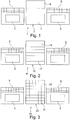
- FIGS. 1-4 show different embodiments of anti-climbing devices according to the invention.
- Figure 1 shows a climbing protection device 1 with a protective shield element 2, which is arranged between two railway buffers 3, 4 and their respective climbing protection elements 5, 6.
- the protective shield element 2 comprises a shield 7 and a cranked section 8.
- the shield 7 is on the impact side (in Fig. 1 against the plane of the drawing, with the upper edge inclined towards the viewer), but the cranked section 8 is even more inclined.
- Shield 7 and cranked section 8, that is to say the entire protective shield element 2 are designed as a continuous surface.
- Figure 2 shows a similar arrangement with a climbing protection device 11, in which the protective shield element 12 is also arranged between the buffers 3, 4 and the climbing protection elements 5, 6. Furthermore, the protective shield element 12 likewise comprises a shield 17 and a cranked section 18, the cranked section 18 and the shield 17 not being designed as a continuous surface, but instead consisting of horizontally extending rods.
- the anti-climbing device 21 comprises a protective shield element 22 with a shield 27 and a cranked section 28, likewise as shown in FIGS Figures 1 and 2 is shown, but shield 27 and cranked section 28 are formed as a lattice structure.
- FIG. 4 A special embodiment is in Figure 4 shown, in which the anti-climbing device 31 has a protective shield element 32, which is also located between the railway buffers 3, 4 and the anti-climbing elements 5, 6.
- the shield 37 is arranged completely between the anti-climbing elements 5, 6.
- the cranked section 38 also additionally projects in a horizontal direction beyond the anti-climbing elements 5, 6, so that a supporting structure can be covered over the entire width by the anti-climbing device 31 and, for example, shields the tank of a tank car.
- Figure 5 is shown schematically in side view how the individual sections of a climbing protection device 1 are inclined on the butt side, while the cranked section 8 is inclined even more on the butt side.
- a claw 9 which is equipped with horizontally running groove structures.
- a rail vehicle 40 is shown that has a support structure 41, on which two buffers 43, 44 are arranged in the lateral area, the Bern area in turn is limited by the geometric specification of how far the plungers 45, 46 of the buffers 43, 44 are pressed can be. In addition, a certain distance from the support structure 41 must be specified. The height of the Bern area is usually assumed to be approx. 2 m. Berner Room B is thus shown in broken lines in a top view and consists of two sub-rooms to the right and left of coupling 47, in which a person can be present when coupling.
- a protective shield element is arranged between the two anti-climbing elements and covers at least part of the area between the anti-climbing elements on the transverse direction of travel.
Landscapes
- Engineering & Computer Science (AREA)
- Mechanical Engineering (AREA)
- Vibration Dampers (AREA)
- Refuge Islands, Traffic Blockers, Or Guard Fence (AREA)
Priority Applications (1)
| Application Number | Priority Date | Filing Date | Title |
|---|---|---|---|
| PL19187061T PL3608197T3 (pl) | 2018-08-07 | 2019-07-18 | Urządzenie przeciwnajazdowe z elementem osłony ochronnej |
Applications Claiming Priority (1)
| Application Number | Priority Date | Filing Date | Title |
|---|---|---|---|
| EP18187772 | 2018-08-07 |
Publications (2)
| Publication Number | Publication Date |
|---|---|
| EP3608197A1 true EP3608197A1 (fr) | 2020-02-12 |
| EP3608197B1 EP3608197B1 (fr) | 2022-03-02 |
Family
ID=63173974
Family Applications (1)
| Application Number | Title | Priority Date | Filing Date |
|---|---|---|---|
| EP19187061.7A Active EP3608197B1 (fr) | 2018-08-07 | 2019-07-18 | Dispositif anti-chevauchement pourvu d'élément d'écran de protection |
Country Status (3)
| Country | Link |
|---|---|
| EP (1) | EP3608197B1 (fr) |
| HU (1) | HUE058948T2 (fr) |
| PL (1) | PL3608197T3 (fr) |
Citations (6)
| Publication number | Priority date | Publication date | Assignee | Title |
|---|---|---|---|---|
| DE19833935A1 (de) * | 1997-07-28 | 1999-02-04 | Hutchinson | Schutzvorrichtung für einen Behälter zum Einschluß von Werkstoffen und Eisenbahnwaggons, welche zumindest eine dieser Vorrichtung enthalten |
| DE102006050028A1 (de) * | 2006-10-24 | 2008-04-30 | Sieghard Schneider | Aufkletterschutzvorrichtung für Schienenfahrzeuge |
| EP2163454A1 (fr) * | 2008-09-16 | 2010-03-17 | Vossloh Locomotives GmbH | Protection contre la montée pour des tampons sur des locomotives |
| DE102013009121B3 (de) * | 2013-05-29 | 2014-07-31 | Waggonbau Graaff Gmbh | Überpufferungsschutz für Schienenfahrzeuge |
| WO2015120882A1 (fr) * | 2014-02-11 | 2015-08-20 | Siemens Aktiengesellschaft | Dispositif de protection anti-montée pour véhicule ferroviaire |
| RU177726U1 (ru) * | 2016-12-27 | 2018-03-06 | РЕЙЛ 1520 АйПи ЛТД | Вагон-цистерна |
-
2019
- 2019-07-18 EP EP19187061.7A patent/EP3608197B1/fr active Active
- 2019-07-18 HU HUE19187061A patent/HUE058948T2/hu unknown
- 2019-07-18 PL PL19187061T patent/PL3608197T3/pl unknown
Patent Citations (6)
| Publication number | Priority date | Publication date | Assignee | Title |
|---|---|---|---|---|
| DE19833935A1 (de) * | 1997-07-28 | 1999-02-04 | Hutchinson | Schutzvorrichtung für einen Behälter zum Einschluß von Werkstoffen und Eisenbahnwaggons, welche zumindest eine dieser Vorrichtung enthalten |
| DE102006050028A1 (de) * | 2006-10-24 | 2008-04-30 | Sieghard Schneider | Aufkletterschutzvorrichtung für Schienenfahrzeuge |
| EP2163454A1 (fr) * | 2008-09-16 | 2010-03-17 | Vossloh Locomotives GmbH | Protection contre la montée pour des tampons sur des locomotives |
| DE102013009121B3 (de) * | 2013-05-29 | 2014-07-31 | Waggonbau Graaff Gmbh | Überpufferungsschutz für Schienenfahrzeuge |
| WO2015120882A1 (fr) * | 2014-02-11 | 2015-08-20 | Siemens Aktiengesellschaft | Dispositif de protection anti-montée pour véhicule ferroviaire |
| RU177726U1 (ru) * | 2016-12-27 | 2018-03-06 | РЕЙЛ 1520 АйПи ЛТД | Вагон-цистерна |
Also Published As
| Publication number | Publication date |
|---|---|
| HUE058948T2 (hu) | 2022-09-28 |
| EP3608197B1 (fr) | 2022-03-02 |
| PL3608197T3 (pl) | 2022-07-11 |
Similar Documents
| Publication | Publication Date | Title |
|---|---|---|
| DE69421043T2 (de) | Stossdämpfende Vorrichtungen und Methode, Gerippe und Fahrzeug die diese stossdämpfende Vorrichtungen aufweisen | |
| WO2008034745A1 (fr) | Module de tête pour un véhicule ferroviaire | |
| DE102018133181B3 (de) | Personenschutzeinrichtung zum Befestigen an der Unterseite eines Schienenfahrzeuges | |
| DE4224998C1 (en) | Protective crash barrier for highways - comprises posts anchored in ground, deformation profile on road side, upper and lower longitudinal rails | |
| EP2277762B1 (fr) | Véhicule ferroviaire doté d'un absorbeur 'énergie, notamment pour un tramway | |
| EP0612647B1 (fr) | Dispositif de protection pour passagers contre des blessures pendant une collision des trains ferroviaires | |
| EP2730700A1 (fr) | Système de retenue de véhicule destiné à être agencé sur un ouvrage de pont | |
| EP2999609B1 (fr) | Véhicule ferroviaire à système d'attelage entrant entièrement dans la structure | |
| DE102015111995B4 (de) | Stoßfängeranordnung mit Schließplatte | |
| EP1633615B1 (fr) | Dispositif anti-chevauchement pour wagon | |
| EP1627956A1 (fr) | Glissière de sécurité routière | |
| EP2808222B1 (fr) | Protection contre l'enchevêtrement pour véhicules ferroviaires | |
| DE602005004131T2 (de) | Verformbarer rahmen für eine fahrzeugkabine | |
| DE102013009121B3 (de) | Überpufferungsschutz für Schienenfahrzeuge | |
| EP3640113A1 (fr) | Dispositif de réception de l'énergie et véhicule ferroviaire | |
| DE4406129A1 (de) | Schutzanordnung an Kraftwagen zum Dämpfen der Aufprallwirkung bei Zusammenstößen | |
| DE102006050028B4 (de) | Vorrichtung an der Fahrzeugfront von Schienenfahrzeugen | |
| DE4332289A1 (de) | Vorrichtung zum Verhindern des Aufkletterns von Schienenfahrzeugen als Folge eines unfallbedingten Aufpralls | |
| DE102012221313B3 (de) | Überpufferungsschutz für Schienenfahrzeuge | |
| EP3608197B1 (fr) | Dispositif anti-chevauchement pourvu d'élément d'écran de protection | |
| EP0370459B1 (fr) | Partie frontale d'une voiture de chemin de fer | |
| EP0816197B1 (fr) | Dispositif protecteur pour véhicules sur rails, notamment pour wagons-citernes ou wagons fermés pour le transport des matières en vrac | |
| DE102006056498B4 (de) | Heck-Unterfahrschutz | |
| EP3415397B1 (fr) | Véhicule ferroviaire ayant une cabine de conducteur de sécurité | |
| DE19855830C1 (de) | Kollisionsschutzeinrichtung für spurgeführte Stadtverkehrsfahrzeuge |
Legal Events
| Date | Code | Title | Description |
|---|---|---|---|
| PUAI | Public reference made under article 153(3) epc to a published international application that has entered the european phase |
Free format text: ORIGINAL CODE: 0009012 |
|
| STAA | Information on the status of an ep patent application or granted ep patent |
Free format text: STATUS: THE APPLICATION HAS BEEN PUBLISHED |
|
| AK | Designated contracting states |
Kind code of ref document: A1 Designated state(s): AL AT BE BG CH CY CZ DE DK EE ES FI FR GB GR HR HU IE IS IT LI LT LU LV MC MK MT NL NO PL PT RO RS SE SI SK SM TR |
|
| AX | Request for extension of the european patent |
Extension state: BA ME |
|
| STAA | Information on the status of an ep patent application or granted ep patent |
Free format text: STATUS: REQUEST FOR EXAMINATION WAS MADE |
|
| 17P | Request for examination filed |
Effective date: 20200505 |
|
| RBV | Designated contracting states (corrected) |
Designated state(s): AL AT BE BG CH CY CZ DE DK EE ES FI FR GB GR HR HU IE IS IT LI LT LU LV MC MK MT NL NO PL PT RO RS SE SI SK SM TR |
|
| GRAP | Despatch of communication of intention to grant a patent |
Free format text: ORIGINAL CODE: EPIDOSNIGR1 |
|
| STAA | Information on the status of an ep patent application or granted ep patent |
Free format text: STATUS: GRANT OF PATENT IS INTENDED |
|
| INTG | Intention to grant announced |
Effective date: 20211019 |
|
| GRAS | Grant fee paid |
Free format text: ORIGINAL CODE: EPIDOSNIGR3 |
|
| GRAA | (expected) grant |
Free format text: ORIGINAL CODE: 0009210 |
|
| STAA | Information on the status of an ep patent application or granted ep patent |
Free format text: STATUS: THE PATENT HAS BEEN GRANTED |
|
| AK | Designated contracting states |
Kind code of ref document: B1 Designated state(s): AL AT BE BG CH CY CZ DE DK EE ES FI FR GB GR HR HU IE IS IT LI LT LU LV MC MK MT NL NO PL PT RO RS SE SI SK SM TR |
|
| REG | Reference to a national code |
Ref country code: GB Ref legal event code: FG4D Free format text: NOT ENGLISH |
|
| REG | Reference to a national code |
Ref country code: CH Ref legal event code: EP Ref country code: AT Ref legal event code: REF Ref document number: 1472024 Country of ref document: AT Kind code of ref document: T Effective date: 20220315 |
|
| REG | Reference to a national code |
Ref country code: DE Ref legal event code: R096 Ref document number: 502019003538 Country of ref document: DE |
|
| REG | Reference to a national code |
Ref country code: IE Ref legal event code: FG4D Free format text: LANGUAGE OF EP DOCUMENT: GERMAN |
|
| REG | Reference to a national code |
Ref country code: RO Ref legal event code: EPE |
|
| REG | Reference to a national code |
Ref country code: LT Ref legal event code: MG9D |
|
| REG | Reference to a national code |
Ref country code: SE Ref legal event code: TRGR |
|
| REG | Reference to a national code |
Ref country code: NL Ref legal event code: MP Effective date: 20220302 |
|
| PG25 | Lapsed in a contracting state [announced via postgrant information from national office to epo] |
Ref country code: RS Free format text: LAPSE BECAUSE OF FAILURE TO SUBMIT A TRANSLATION OF THE DESCRIPTION OR TO PAY THE FEE WITHIN THE PRESCRIBED TIME-LIMIT Effective date: 20220302 Ref country code: NO Free format text: LAPSE BECAUSE OF FAILURE TO SUBMIT A TRANSLATION OF THE DESCRIPTION OR TO PAY THE FEE WITHIN THE PRESCRIBED TIME-LIMIT Effective date: 20220602 Ref country code: LT Free format text: LAPSE BECAUSE OF FAILURE TO SUBMIT A TRANSLATION OF THE DESCRIPTION OR TO PAY THE FEE WITHIN THE PRESCRIBED TIME-LIMIT Effective date: 20220302 Ref country code: HR Free format text: LAPSE BECAUSE OF FAILURE TO SUBMIT A TRANSLATION OF THE DESCRIPTION OR TO PAY THE FEE WITHIN THE PRESCRIBED TIME-LIMIT Effective date: 20220302 Ref country code: ES Free format text: LAPSE BECAUSE OF FAILURE TO SUBMIT A TRANSLATION OF THE DESCRIPTION OR TO PAY THE FEE WITHIN THE PRESCRIBED TIME-LIMIT Effective date: 20220302 Ref country code: BG Free format text: LAPSE BECAUSE OF FAILURE TO SUBMIT A TRANSLATION OF THE DESCRIPTION OR TO PAY THE FEE WITHIN THE PRESCRIBED TIME-LIMIT Effective date: 20220602 |
|
| PG25 | Lapsed in a contracting state [announced via postgrant information from national office to epo] |
Ref country code: LV Free format text: LAPSE BECAUSE OF FAILURE TO SUBMIT A TRANSLATION OF THE DESCRIPTION OR TO PAY THE FEE WITHIN THE PRESCRIBED TIME-LIMIT Effective date: 20220302 Ref country code: GR Free format text: LAPSE BECAUSE OF FAILURE TO SUBMIT A TRANSLATION OF THE DESCRIPTION OR TO PAY THE FEE WITHIN THE PRESCRIBED TIME-LIMIT Effective date: 20220603 Ref country code: FI Free format text: LAPSE BECAUSE OF FAILURE TO SUBMIT A TRANSLATION OF THE DESCRIPTION OR TO PAY THE FEE WITHIN THE PRESCRIBED TIME-LIMIT Effective date: 20220302 |
|
| REG | Reference to a national code |
Ref country code: HU Ref legal event code: AG4A Ref document number: E058948 Country of ref document: HU |
|
| PG25 | Lapsed in a contracting state [announced via postgrant information from national office to epo] |
Ref country code: NL Free format text: LAPSE BECAUSE OF FAILURE TO SUBMIT A TRANSLATION OF THE DESCRIPTION OR TO PAY THE FEE WITHIN THE PRESCRIBED TIME-LIMIT Effective date: 20220302 |
|
| PG25 | Lapsed in a contracting state [announced via postgrant information from national office to epo] |
Ref country code: SM Free format text: LAPSE BECAUSE OF FAILURE TO SUBMIT A TRANSLATION OF THE DESCRIPTION OR TO PAY THE FEE WITHIN THE PRESCRIBED TIME-LIMIT Effective date: 20220302 Ref country code: SK Free format text: LAPSE BECAUSE OF FAILURE TO SUBMIT A TRANSLATION OF THE DESCRIPTION OR TO PAY THE FEE WITHIN THE PRESCRIBED TIME-LIMIT Effective date: 20220302 Ref country code: PT Free format text: LAPSE BECAUSE OF FAILURE TO SUBMIT A TRANSLATION OF THE DESCRIPTION OR TO PAY THE FEE WITHIN THE PRESCRIBED TIME-LIMIT Effective date: 20220704 Ref country code: EE Free format text: LAPSE BECAUSE OF FAILURE TO SUBMIT A TRANSLATION OF THE DESCRIPTION OR TO PAY THE FEE WITHIN THE PRESCRIBED TIME-LIMIT Effective date: 20220302 |
|
| PG25 | Lapsed in a contracting state [announced via postgrant information from national office to epo] |
Ref country code: IS Free format text: LAPSE BECAUSE OF FAILURE TO SUBMIT A TRANSLATION OF THE DESCRIPTION OR TO PAY THE FEE WITHIN THE PRESCRIBED TIME-LIMIT Effective date: 20220702 Ref country code: AL Free format text: LAPSE BECAUSE OF FAILURE TO SUBMIT A TRANSLATION OF THE DESCRIPTION OR TO PAY THE FEE WITHIN THE PRESCRIBED TIME-LIMIT Effective date: 20220302 |
|
| REG | Reference to a national code |
Ref country code: DE Ref legal event code: R097 Ref document number: 502019003538 Country of ref document: DE |
|
| PLBE | No opposition filed within time limit |
Free format text: ORIGINAL CODE: 0009261 |
|
| STAA | Information on the status of an ep patent application or granted ep patent |
Free format text: STATUS: NO OPPOSITION FILED WITHIN TIME LIMIT |
|
| PG25 | Lapsed in a contracting state [announced via postgrant information from national office to epo] |
Ref country code: DK Free format text: LAPSE BECAUSE OF FAILURE TO SUBMIT A TRANSLATION OF THE DESCRIPTION OR TO PAY THE FEE WITHIN THE PRESCRIBED TIME-LIMIT Effective date: 20220302 |
|
| 26N | No opposition filed |
Effective date: 20221205 |
|
| PG25 | Lapsed in a contracting state [announced via postgrant information from national office to epo] |
Ref country code: SI Free format text: LAPSE BECAUSE OF FAILURE TO SUBMIT A TRANSLATION OF THE DESCRIPTION OR TO PAY THE FEE WITHIN THE PRESCRIBED TIME-LIMIT Effective date: 20220302 Ref country code: MC Free format text: LAPSE BECAUSE OF FAILURE TO SUBMIT A TRANSLATION OF THE DESCRIPTION OR TO PAY THE FEE WITHIN THE PRESCRIBED TIME-LIMIT Effective date: 20220302 |
|
| REG | Reference to a national code |
Ref country code: CH Ref legal event code: PL |
|
| REG | Reference to a national code |
Ref country code: BE Ref legal event code: MM Effective date: 20220731 |
|
| PG25 | Lapsed in a contracting state [announced via postgrant information from national office to epo] |
Ref country code: LU Free format text: LAPSE BECAUSE OF NON-PAYMENT OF DUE FEES Effective date: 20220718 Ref country code: LI Free format text: LAPSE BECAUSE OF NON-PAYMENT OF DUE FEES Effective date: 20220731 Ref country code: CH Free format text: LAPSE BECAUSE OF NON-PAYMENT OF DUE FEES Effective date: 20220731 |
|
| PG25 | Lapsed in a contracting state [announced via postgrant information from national office to epo] |
Ref country code: BE Free format text: LAPSE BECAUSE OF NON-PAYMENT OF DUE FEES Effective date: 20220731 |
|
| P01 | Opt-out of the competence of the unified patent court (upc) registered |
Effective date: 20230524 |
|
| PG25 | Lapsed in a contracting state [announced via postgrant information from national office to epo] |
Ref country code: IT Free format text: LAPSE BECAUSE OF FAILURE TO SUBMIT A TRANSLATION OF THE DESCRIPTION OR TO PAY THE FEE WITHIN THE PRESCRIBED TIME-LIMIT Effective date: 20220302 Ref country code: IE Free format text: LAPSE BECAUSE OF NON-PAYMENT OF DUE FEES Effective date: 20220718 |
|
| PGFP | Annual fee paid to national office [announced via postgrant information from national office to epo] |
Ref country code: GB Payment date: 20230724 Year of fee payment: 5 |
|
| PGFP | Annual fee paid to national office [announced via postgrant information from national office to epo] |
Ref country code: SE Payment date: 20230724 Year of fee payment: 5 |
|
| PG25 | Lapsed in a contracting state [announced via postgrant information from national office to epo] |
Ref country code: MK Free format text: LAPSE BECAUSE OF FAILURE TO SUBMIT A TRANSLATION OF THE DESCRIPTION OR TO PAY THE FEE WITHIN THE PRESCRIBED TIME-LIMIT Effective date: 20220302 Ref country code: CY Free format text: LAPSE BECAUSE OF FAILURE TO SUBMIT A TRANSLATION OF THE DESCRIPTION OR TO PAY THE FEE WITHIN THE PRESCRIBED TIME-LIMIT Effective date: 20220302 |
|
| PG25 | Lapsed in a contracting state [announced via postgrant information from national office to epo] |
Ref country code: MT Free format text: LAPSE BECAUSE OF FAILURE TO SUBMIT A TRANSLATION OF THE DESCRIPTION OR TO PAY THE FEE WITHIN THE PRESCRIBED TIME-LIMIT Effective date: 20220302 |
|
| PGFP | Annual fee paid to national office [announced via postgrant information from national office to epo] |
Ref country code: HU Payment date: 20240717 Year of fee payment: 6 |
|
| REG | Reference to a national code |
Ref country code: SE Ref legal event code: EUG |
|
| REG | Reference to a national code |
Ref country code: DE Ref legal event code: R082 Ref document number: 502019003538 Country of ref document: DE Representative=s name: RAVENSPAT PATENTANWAELTE PARTNERSCHAFT MBB, DE |
|
| GBPC | Gb: european patent ceased through non-payment of renewal fee |
Effective date: 20240718 |
|
| PG25 | Lapsed in a contracting state [announced via postgrant information from national office to epo] |
Ref country code: GB Free format text: LAPSE BECAUSE OF NON-PAYMENT OF DUE FEES Effective date: 20240718 |
|
| REG | Reference to a national code |
Ref country code: AT Ref legal event code: MM01 Ref document number: 1472024 Country of ref document: AT Kind code of ref document: T Effective date: 20240718 |
|
| PGFP | Annual fee paid to national office [announced via postgrant information from national office to epo] |
Ref country code: DE Payment date: 20250722 Year of fee payment: 7 |
|
| PG25 | Lapsed in a contracting state [announced via postgrant information from national office to epo] |
Ref country code: SE Free format text: LAPSE BECAUSE OF NON-PAYMENT OF DUE FEES Effective date: 20240719 |
|
| PGFP | Annual fee paid to national office [announced via postgrant information from national office to epo] |
Ref country code: PL Payment date: 20250707 Year of fee payment: 7 |
|
| PG25 | Lapsed in a contracting state [announced via postgrant information from national office to epo] |
Ref country code: AT Free format text: LAPSE BECAUSE OF NON-PAYMENT OF DUE FEES Effective date: 20240718 |
|
| PGFP | Annual fee paid to national office [announced via postgrant information from national office to epo] |
Ref country code: FR Payment date: 20250723 Year of fee payment: 7 |
|
| PGFP | Annual fee paid to national office [announced via postgrant information from national office to epo] |
Ref country code: CZ Payment date: 20250708 Year of fee payment: 7 |
|
| PGFP | Annual fee paid to national office [announced via postgrant information from national office to epo] |
Ref country code: RO Payment date: 20250710 Year of fee payment: 7 |
|
| PG25 | Lapsed in a contracting state [announced via postgrant information from national office to epo] |
Ref country code: TR Free format text: LAPSE BECAUSE OF FAILURE TO SUBMIT A TRANSLATION OF THE DESCRIPTION OR TO PAY THE FEE WITHIN THE PRESCRIBED TIME-LIMIT Effective date: 20220302 |
|
| PG25 | Lapsed in a contracting state [announced via postgrant information from national office to epo] |
Ref country code: HU Free format text: LAPSE BECAUSE OF NON-PAYMENT OF DUE FEES Effective date: 20250719 |
|
| PGFP | Annual fee paid to national office [announced via postgrant information from national office to epo] |
Ref country code: AT Payment date: 20260410 Year of fee payment: 5 |