EP3608295A1 - Verfahren zur behandlung organischer abwässer und vorrichtung zur behandlung organischer abwässer - Google Patents
Verfahren zur behandlung organischer abwässer und vorrichtung zur behandlung organischer abwässer Download PDFInfo
- Publication number
- EP3608295A1 EP3608295A1 EP18780388.7A EP18780388A EP3608295A1 EP 3608295 A1 EP3608295 A1 EP 3608295A1 EP 18780388 A EP18780388 A EP 18780388A EP 3608295 A1 EP3608295 A1 EP 3608295A1
- Authority
- EP
- European Patent Office
- Prior art keywords
- membrane separation
- organic wastewater
- tank
- biological treatment
- separation device
- Prior art date
- Legal status (The legal status is an assumption and is not a legal conclusion. Google has not performed a legal analysis and makes no representation as to the accuracy of the status listed.)
- Granted
Links
Images


Classifications
-
- C—CHEMISTRY; METALLURGY
- C02—TREATMENT OF WATER, WASTE WATER, SEWAGE, OR SLUDGE
- C02F—TREATMENT OF WATER, WASTE WATER, SEWAGE, OR SLUDGE
- C02F3/00—Biological treatment of water, waste water, or sewage
- C02F3/30—Aerobic and anaerobic processes
- C02F3/302—Nitrification and denitrification treatment
- C02F3/303—Nitrification and denitrification treatment characterised by the nitrification
-
- C—CHEMISTRY; METALLURGY
- C02—TREATMENT OF WATER, WASTE WATER, SEWAGE, OR SLUDGE
- C02F—TREATMENT OF WATER, WASTE WATER, SEWAGE, OR SLUDGE
- C02F3/00—Biological treatment of water, waste water, or sewage
- C02F3/006—Regulation methods for biological treatment
-
- C—CHEMISTRY; METALLURGY
- C02—TREATMENT OF WATER, WASTE WATER, SEWAGE, OR SLUDGE
- C02F—TREATMENT OF WATER, WASTE WATER, SEWAGE, OR SLUDGE
- C02F3/00—Biological treatment of water, waste water, or sewage
- C02F3/02—Aerobic processes
- C02F3/12—Activated sludge processes
- C02F3/1205—Particular type of activated sludge processes
- C02F3/1215—Combinations of activated sludge treatment with precipitation, flocculation, coagulation and separation of phosphates
-
- C—CHEMISTRY; METALLURGY
- C02—TREATMENT OF WATER, WASTE WATER, SEWAGE, OR SLUDGE
- C02F—TREATMENT OF WATER, WASTE WATER, SEWAGE, OR SLUDGE
- C02F3/00—Biological treatment of water, waste water, or sewage
- C02F3/02—Aerobic processes
- C02F3/12—Activated sludge processes
- C02F3/1236—Particular type of activated sludge installations
- C02F3/1268—Membrane bioreactor systems
- C02F3/1273—Submerged membrane bioreactors
-
- C—CHEMISTRY; METALLURGY
- C02—TREATMENT OF WATER, WASTE WATER, SEWAGE, OR SLUDGE
- C02F—TREATMENT OF WATER, WASTE WATER, SEWAGE, OR SLUDGE
- C02F3/00—Biological treatment of water, waste water, or sewage
- C02F3/02—Aerobic processes
- C02F3/12—Activated sludge processes
- C02F3/20—Activated sludge processes using diffusers
-
- C—CHEMISTRY; METALLURGY
- C02—TREATMENT OF WATER, WASTE WATER, SEWAGE, OR SLUDGE
- C02F—TREATMENT OF WATER, WASTE WATER, SEWAGE, OR SLUDGE
- C02F3/00—Biological treatment of water, waste water, or sewage
- C02F3/02—Aerobic processes
- C02F3/12—Activated sludge processes
- C02F3/22—Activated sludge processes using circulation pipes
- C02F3/223—Activated sludge processes using circulation pipes using "air-lift"
-
- C—CHEMISTRY; METALLURGY
- C02—TREATMENT OF WATER, WASTE WATER, SEWAGE, OR SLUDGE
- C02F—TREATMENT OF WATER, WASTE WATER, SEWAGE, OR SLUDGE
- C02F3/00—Biological treatment of water, waste water, or sewage
- C02F3/30—Aerobic and anaerobic processes
- C02F3/302—Nitrification and denitrification treatment
- C02F3/305—Nitrification and denitrification treatment characterised by the denitrification
-
- C—CHEMISTRY; METALLURGY
- C02—TREATMENT OF WATER, WASTE WATER, SEWAGE, OR SLUDGE
- C02F—TREATMENT OF WATER, WASTE WATER, SEWAGE, OR SLUDGE
- C02F2209/00—Controlling or monitoring parameters in water treatment
- C02F2209/005—Processes using a programmable logic controller [PLC]
-
- C—CHEMISTRY; METALLURGY
- C02—TREATMENT OF WATER, WASTE WATER, SEWAGE, OR SLUDGE
- C02F—TREATMENT OF WATER, WASTE WATER, SEWAGE, OR SLUDGE
- C02F2209/00—Controlling or monitoring parameters in water treatment
- C02F2209/03—Pressure
-
- C—CHEMISTRY; METALLURGY
- C02—TREATMENT OF WATER, WASTE WATER, SEWAGE, OR SLUDGE
- C02F—TREATMENT OF WATER, WASTE WATER, SEWAGE, OR SLUDGE
- C02F2209/00—Controlling or monitoring parameters in water treatment
- C02F2209/14—NH3-N
-
- C—CHEMISTRY; METALLURGY
- C02—TREATMENT OF WATER, WASTE WATER, SEWAGE, OR SLUDGE
- C02F—TREATMENT OF WATER, WASTE WATER, SEWAGE, OR SLUDGE
- C02F2209/00—Controlling or monitoring parameters in water treatment
- C02F2209/16—Total nitrogen (tkN-N)
-
- C—CHEMISTRY; METALLURGY
- C02—TREATMENT OF WATER, WASTE WATER, SEWAGE, OR SLUDGE
- C02F—TREATMENT OF WATER, WASTE WATER, SEWAGE, OR SLUDGE
- C02F2209/00—Controlling or monitoring parameters in water treatment
- C02F2209/40—Liquid flow rate
-
- C—CHEMISTRY; METALLURGY
- C02—TREATMENT OF WATER, WASTE WATER, SEWAGE, OR SLUDGE
- C02F—TREATMENT OF WATER, WASTE WATER, SEWAGE, OR SLUDGE
- C02F2209/00—Controlling or monitoring parameters in water treatment
- C02F2209/42—Liquid level
-
- C—CHEMISTRY; METALLURGY
- C02—TREATMENT OF WATER, WASTE WATER, SEWAGE, OR SLUDGE
- C02F—TREATMENT OF WATER, WASTE WATER, SEWAGE, OR SLUDGE
- C02F2301/00—General aspects of water treatment
- C02F2301/04—Flow arrangements
- C02F2301/043—Treatment of partial or bypass streams
-
- C—CHEMISTRY; METALLURGY
- C02—TREATMENT OF WATER, WASTE WATER, SEWAGE, OR SLUDGE
- C02F—TREATMENT OF WATER, WASTE WATER, SEWAGE, OR SLUDGE
- C02F2301/00—General aspects of water treatment
- C02F2301/08—Multistage treatments, e.g. repetition of the same process step under different conditions
-
- C—CHEMISTRY; METALLURGY
- C02—TREATMENT OF WATER, WASTE WATER, SEWAGE, OR SLUDGE
- C02F—TREATMENT OF WATER, WASTE WATER, SEWAGE, OR SLUDGE
- C02F2303/00—Specific treatment goals
- C02F2303/16—Regeneration of sorbents, filters
-
- C—CHEMISTRY; METALLURGY
- C02—TREATMENT OF WATER, WASTE WATER, SEWAGE, OR SLUDGE
- C02F—TREATMENT OF WATER, WASTE WATER, SEWAGE, OR SLUDGE
- C02F3/00—Biological treatment of water, waste water, or sewage
- C02F3/02—Aerobic processes
- C02F3/12—Activated sludge processes
- C02F3/1205—Particular type of activated sludge processes
- C02F3/121—Multistep treatment
-
- C—CHEMISTRY; METALLURGY
- C02—TREATMENT OF WATER, WASTE WATER, SEWAGE, OR SLUDGE
- C02F—TREATMENT OF WATER, WASTE WATER, SEWAGE, OR SLUDGE
- C02F3/00—Biological treatment of water, waste water, or sewage
- C02F3/02—Aerobic processes
- C02F3/12—Activated sludge processes
- C02F3/1205—Particular type of activated sludge processes
- C02F3/1221—Particular type of activated sludge processes comprising treatment of the recirculated sludge
-
- C—CHEMISTRY; METALLURGY
- C02—TREATMENT OF WATER, WASTE WATER, SEWAGE, OR SLUDGE
- C02F—TREATMENT OF WATER, WASTE WATER, SEWAGE, OR SLUDGE
- C02F3/00—Biological treatment of water, waste water, or sewage
- C02F3/02—Aerobic processes
- C02F3/12—Activated sludge processes
- C02F3/1236—Particular type of activated sludge installations
- C02F3/1257—Oxidation ditches
-
- Y—GENERAL TAGGING OF NEW TECHNOLOGICAL DEVELOPMENTS; GENERAL TAGGING OF CROSS-SECTIONAL TECHNOLOGIES SPANNING OVER SEVERAL SECTIONS OF THE IPC; TECHNICAL SUBJECTS COVERED BY FORMER USPC CROSS-REFERENCE ART COLLECTIONS [XRACs] AND DIGESTS
- Y02—TECHNOLOGIES OR APPLICATIONS FOR MITIGATION OR ADAPTATION AGAINST CLIMATE CHANGE
- Y02W—CLIMATE CHANGE MITIGATION TECHNOLOGIES RELATED TO WASTEWATER TREATMENT OR WASTE MANAGEMENT
- Y02W10/00—Technologies for wastewater treatment
- Y02W10/10—Biological treatment of water, waste water, or sewage
Definitions
- the present invention relates to an organic wastewater treatment method and an organic wastewater treatment device.
- Patent Document 1 discloses a nitrogen-containing wastewater treatment facility which treats nitrogen-containing wastewater using activated sludge with a nitrogen removal rate of 90% or more, and which can also be made compact.
- the nitrogen-containing wastewater treatment facility includes a plurality of anaerobic tanks and aerobic tanks connected in series alternately in the order of anaerobic tank and aerobic tank, a supply path for supplying the nitrogen-containing wastewater to a first stage anaerobic tank and to at least one anaerobic tank after the second stage, while the last stage aerobic tank includes an immersion type separation device for separating the activated sludge so as to obtain treated liquid, and a flow path to return liquid containing the activated sludge from the last stage aerobic tank to the first stage anaerobic tank.
- Patent Document 2 discloses a membrane separation apparatus which is capable of performing an advanced treatment with a single treatment tank.
- the membrane separation apparatus includes an endless-type treatment tank for biologically treating water to be treated, a plurality of membrane units for membrane-separating the water to be treated, and a raw water tank for storing the water to be treated which is to be supplied to the treatment tank.
- a swirling flow of the water to be treated is formed in the treatment tank, and the plurality of membrane units are installed at intervals in the swirling flow in a flow direction thereof.
- the raw water tank is provided on an inner side of the swirling flow, and the water to be treated is supplied from the raw water tank to the treatment tank in multiple stages along the flow direction of the swirling flow using a supply means.
- any of the above-described wastewater treatment facilities can realize a high denitrification performance in the anaerobic treatment region under a high BOD concentration.
- an object of the present invention is to provide an organic wastewater treatment method and an organic wastewater treatment device which can efficiently perform biological treatment in accordance with the properties of nitrogen-containing organic wastewater.
- a first characteristic configuration of the organic wastewater treatment method according to the present invention is an organic wastewater treatment method for biologically treating nitrogen-containing organic wastewater in activated sludge in an organic wastewater treatment device.
- the organic wastewater treatment device includes (a) a biological treatment tank in which a plurality of biological treatment units are connected in series, each biological treatment unit having a pair of an anoxic tank disposed on an upstream side along a flow of the organic wastewater, and an aerobic tank disposed on a downstream side of the flow, a membrane separation device being immersed in activated sludge in the aerobic tank, and (b) a sludge return path for returning the activated sludge from the aerobic tank disposed on a most downstream side to the anoxic tank disposed on a most upstream side.
- the organic wastewater treatment method includes (i) dividing and supplying the organic wastewater to the anoxic tank of each biological treatment unit, (ii) biologically treating the organic wastewater by repeating a denitrification process in the anoxic tank and a nitrification process in the aerobic tank, (iii) discharging membrane-permeated liquid from the membrane separation device of each biological treatment unit as treated water, and (iv) determining for each biological treatment unit whether to stop the membrane separation device which is operating ("operating membrane separation device") or whether to start the membrane separation device which has been stopped (“stopped membrane separation device”) based on at least one of an inflow amount of the organic wastewater, a tank water level, a transmembrane pressure difference of each membrane separation device, a T-N of the treated water, and an NH 3 -N concentration of the treated water as an index.
- At least one of the inflow amount of the organic wastewater, the tank water level, the transmembrane pressure difference of each membrane separation device, the T-N of the treated water, and the NH 3 -N concentration of the treated water can be used.
- a second characteristic configuration of the organic wastewater treatment method provides, in addition to the first characteristic configuration described above, adjusting an injection amount of a flocculant injected into the activated sludge in the biological treatment tank based on an operating status of the membrane separation device.
- an anaerobic condition in the corresponding aerobic tank is strengthened because the aeration device therein is stopped. If the activated sludge in this condition flows into the adjacent anoxic tank on the downstream side, a discharge of phosphorus from the activated sludge becomes more prominent due to the influence of the organic wastewater supplied to the anoxic tank.
- the membrane separation device subject to a stop is switched in every predetermined time period.
- a fourth characteristic configuration of the organic wastewater treatment method provides, in addition to the above-mentioned third characteristic configuration, sequentially performing a membrane cleaning process for all of the membrane separation devices by injecting a cleaning liquid to the stopped membrane separation device from a secondary side thereof, wherein a membrane filtration flow rate for the membrane separations which have been cleaned is set equal to or smaller than that for the membrane separation devices which have not been cleaned until all of the membrane separation devices have been cleaned.
- an upper end of an opening of an outflow port through which the activated sludge flows from the aerobic tank into the anoxic tank is submerged, and an inflow rate of the activated sludge is equal to or smaller than 0.5m/sec.
- the inflow rate of the activated sludge at the opening of the inflow port equal to or smaller than 0.5 m/sec, it is possible to suppress a water level difference between the aerobic tank and the anoxic tank due to a pressure loss when the activated sludge passes through the opening, thereby improving uniformity in the aeration for the activated sludge in each aerobic tank.
- a first characteristic configuration of a wastewater treatment device provides an organic wastewater treatment device for biologically treating nitrogen-containing organic wastewater in activated sludge.
- the organic wastewater treatment device includes (a) a biological treatment tank in which a plurality of biological treatment units are connected in series, each biological treatment unit having a pair of an anoxic tank disposed on an upstream side along a flow of the organic wastewater, and an aerobic tank disposed on a downstream side of the flow, a membrane separation device being immersed in activated sludge in the aerobic tank, (b) a sludge return path for returning the activated sludge from the aerobic tank disposed on a most downstream side to the anoxic tank disposed on a most upstream side; (c) a raw water supply path for dividing and supplying the organic wastewater to the anoxic tank of each biological treatment unit; (d) a treated water discharge path for discharging membrane-permeated liquid from the membrane separation device of each biological treatment unit as treated water; (e) a measurement device for measuring at least one
- a second characteristic configuration of the organic wastewater treatment device includes, in addition to the first characteristic configuration described above, the controller is further configured to adjust an injection amount of a flocculant injected into the activated sludge in the biological treatment tank in accordance with an operating status of the membrane separation device.
- the controller switches the membrane separation device subject to a stop in every predetermined time period.
- an upper end of an opening of an outflow port for sending the activated sludge from the aerobic tank toward the adjacent anoxic tank on a downstream side along the flow of the organic wastewater is positioned at or lower than 30 cm from a water surface of the aerobic tank.
- the activated sludge starts settling down in the tank.
- the upper end of the opening of the outflow port through which the activated sludge flows toward the anoxic tank is positioned at or lower than 30 cm from the water surface of the aerobic tank, it is possible to avoid such an undesirable condition that only supernatant liquid flows into the anoxic tank, whereby the activated sludge can be transferred to the anoxic tank even when the membrane separation device is stopped.
- an organic wastewater treatment method and an organic wastewater treatment device which can efficiently perform biological treatment according to the properties of the nitrogen-containing organic wastewater.
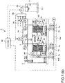
- the organic wastewater treatment device 1 is an organic wastewater treatment device for biologically treating nitrogen-containing organic wastewater in activated sludge so as to obtain treated water, and includes a biological treatment tank 2.
- a pair of an anoxic tank 10 and an aerobic tank 20 forms a biological treatment unit, and a plurality of biological treatment units (four pairs of biological treatment units in this embodiment) are connected in series and in an endless manner along a flow of the organic wastewater.
- the plurality of biological treatment units may be formed by dividing a single biological treatment tank 2 into a plurality of sections, or the biological treatment tank 2 may also be constructed by arranging a plurality of pairs of the individual anoxic tank 10 and aerobic tank 20 along the flow of the organic wastewater.
- the biological treatment tank 2 may be configured in a straight line, and a water channel or pipeline may be separately provided as a sludge return path for returning the activated sludge from the aerobic tank 20 disposed on the most downstream side to the anoxic tank 10 disposed on the most upstream side.
- the organic wastewater which is raw water, is divided into an approximately equal amount and supplied to each anoxic tank 10 through a raw water supply path 3, and after being treated by an anaerobic denitrification process in each anoxic tank 10, flows into the aerobic tank 20 on the downstream side to be aerobically treated therein.
- a membrane separation device 30 is immersed in each aerobic tank 20, and an auxiliary air diffuser 40 for the aerobic treatment is installed in the vicinity of the membrane separation device 30.
- the anoxic tank 10 (10a) on the most upstream side is provided with an air lift pump AP. Air bubbles is supplied from a blower B to an air lift pipe through a valve 10 so as to generate an upward flow in the air lift pipe, by which the organic wastewater is sent to the aerobic tank 20 (20a) on the downstream side along with the activated sludge. After that, the organic wastewater naturally flows down through the anoxic tank 10 (10b), the aerobic tank 20 (20b), the anoxic tank 10 (10c), the aerobic tank 20 (20c), and the anoxic tank 10 (10d), and the aerobic tank 20 (20d) in this order.
- the air lift pump AP is provided in the anoxic tank 10, compared with such a case in which the air lift pump AP is provided in the aerobic tank 20 so as to flow the liquid into the anoxic tank 10, the dissolved oxygen amount DO in the anoxic tank 10 does not increase.
- four pairs of biological treatment units are arranged in an endless manner along the flow of the organic wastewater, and the aerobic tank 20 (20d) disposed on the most downstream side and the anoxic tank 10 (10a) disposed on the most upstream side are arranged side by side with a partition wall interposed therebetween.
- the sludge return path for returning the activated sludge in the most downstream aerobic tank 20 (20d) to the most upstream anoxic tank 10 (10a) is formed in a portion of the partition wall.
- a partition wall W1 is formed between the anoxic tank 10 and the aerobic tank 20, and a cutout 11 (see FIG. 1(b) ) is provided on a part of an upper end side of the partition wall W1, such that the organic wastewater containing the activated sludge from the anoxic tank 10 overflows into the aerobic tank 20.
- a partition wall W2 is formed between the aerobic tank 20 and the anoxic tank 10, and an outflow port 21 for the organic wastewater containing the activated sludge is provided at a position corresponding to the vicinity of the bottom of the membrane separation device 30 in the vertical direction.
- An upper end of the opening which serves as the outflow port 21 is submerged, and is disposed at or lower than 30 cm from the water surface of the aerobic tank 20.
- An outflow rate of the activated sludge from the outflow port 21 is set equal to or smaller than 0.5 m/sec.
- the outflow port 21 formed in the aerobic tank 20 (20d) on the most downstream side serves as the sludge return path described above.
- an arrow shown with a two-dot chain line illustrates a circulating flow formed by the activated sludge flowing within the biological treatment unit.
- the membrane separation device 30 includes a plurality of membrane elements 31 and an aeration device 32 installed below the membrane elements 31 (see FIG. 1(b) ).
- the plurality of membrane elements 31 are accommodated in a casing by arranging them in up-and-down two stages with a predetermined interval such that each membrane surface has an upright posture.
- the membrane element 31 is formed by disposing a separation membrane 31b on both of the front and back surfaces of a resin membrane support 31a which has a water collecting pipe 31c at an upper portion thereof.
- the separation membrane 31b is formed of a micro filtration membrane including a porous organic polymer membrane having a nominal pore diameter of about 0.4 ⁇ m and provided on a surface of a nonwoven fabric.
- the types of the separation membrane 31b and the membrane element 31 are not limited to the above-described embodiments, but any type of separation membrane and any form of membrane element (hollow fiber membrane element, tubular membrane element, monolith membrane element, etc.) can be used.
- the treated water which has permeated the separation membrane 31b flows along a groove formed in the membrane support 31a into a water collecting pipe 31c. Then, as shown in FIGS. 1 (a) and 1 (b) , the treated water is sent from the water collecting pipe 31c to an air separation tank 35 via a respective header pipe 34, and then is collected into a treated water tank 37 through a liquid transfer pipe 36 connected to the air separation tank 35.
- the header pipes 34 are provided with respective valves V5, V6, V7, and V8 for a flow rate adjustment, and a liquid transfer pipe 36 is provided with a suction pump P.
- the amount of permeated water from each membrane separation device 30 is adjusted by a pressure control with the suction pump P and an opening control with the valves V5, V6, V7, and V8.
- a pressure sensor Pm is provided to an upstream side of each of the valves V5, V6, V7, and V8 in the respective header pipes 34.
- a reference symbol M indicates a motor for adjusting the opening of the valves.
- a treated water discharge path is formed by a path of the wastewater flowing from the water collection pipe 31c through the header pipe 34 into the air separation tank 35, from the air separation tank 35 through the liquid transfer pipe 36 connected thereto, into a treated water tank 37 where the treated water is collected.
- a main blow tube Tm is connected to the blower B, and four secondary blow tubes Ts are branched from the main blow pipe Tm, and a respective aeration device 32 is connected to each secondary blow tube Ts.
- valves V1, V2, ... are respectively provided to the secondary blow tubes Ts for a flow rate control, whereby an aeration amount, stopping and starting of the aeration are controlled.
- the organic wastewater is aerated together with the activated sludge in the aerobic tank 20 by an auxiliary air diffuser 40, whereby the organic substance is decomposed and ammonia nitrogen is nitrified to nitrate nitrogen, and part of the organic wastewater is solid-liquid separated by the membrane separation device 30 into the treated water.
- the organic wastewater that has been nitrified in the aerobic tank 20 flows, together with the activated sludge, into the adjacent anoxic tank 10 on the downstream side, in which a denitrification process proceeds to remove nitrate nitrogen by reducing into nitrogen gas.
- an inflow amount of the raw water per unit time is Q
- an inflow amount of the raw water into each anoxic tank 10 is Q/4
- a total amount Q of permeated liquid is extracted from each membrane separation device 30 as the treated water, and an amount 3Q of the activated sludge in the aerobic tank 20 (20d) at the most downstream side is returned to the anoxic tank 10 (10a) at the most upstream side via the sludge return path, a substantial circulation ratio of the sludge becomes 3 ⁇ 4 so as to realize a high circulation ratio of 12Q.
- the organic wastewater treatment device 1 is provided with a flow meter for measuring an amount of inflow of the organic wastewater, a liquid level meter for measuring a tank water level of the tank, a pressure sensor for measuring the transmembrane pressure difference of each membrane separation device, and a plurality of measuring instruments such as a measurement device S provided to the treated water tank 37 for measuring the T-N and the NH 3 -N concentration of the treated water.
- the organic wastewater treatment device 1 further includes a control unit 60 which serves as a controller for controlling operations of the organic wastewater treatment device 1 based on the values measured by these measuring instruments.
- the control unit 60 is implemented in a control panel with a computer including an arithmetic circuit, an input circuit, an output circuit, and the like.
- the control unit 60 controls the operation of each membrane separation device 30, while monitoring the measured values from these measuring instruments, such as a degree of the inflow amount of the raw water, the water level of the biological treatment tank 2, the value of each pressure sensor Pm, and the value of the measurement device S provided to the treated water tank 37 for measuring the total nitrogen (T-N) concentration, such that a filtration operation state and a relaxation operation state are repeatedly performed as the two operation modes.
- these measuring instruments such as a degree of the inflow amount of the raw water, the water level of the biological treatment tank 2, the value of each pressure sensor Pm, and the value of the measurement device S provided to the treated water tank 37 for measuring the total nitrogen (T-N) concentration, such that a filtration operation state and a relaxation operation state are repeatedly performed as the two operation modes.
- the filtration operation state refers to a state in which the membrane-permeated water is drawn from the water collecting pipe 31c as the treated water while aeration is performed by the aeration apparatus 32.
- the relaxation operation state refers to a state in which a surface of the separation membrane 31b is cleaned by an upward flow which is generated by aeration bubbles from the aeration device 32, while the valves provided to the header pipe 34 are closed or the suction pump P is closed.
- the control unit 60 alternately repeats the filtration operation for a first predetermined time period (for example, 9 minutes) and the relaxation operation for a second predetermined time period (for example, 1 minute).
- control unit 60 determines whether to stop the membrane separation device 30 which is being operated or whether to start the membrane separation device 30 which has been stopped for each biological treatment unit, based on at least one of the inflow amount of organic wastewater, the water level of the tank, the transmembrane pressure difference of each membrane separation device, the T-N of the treated water, and the NH 3 -N concentration of the treated water which are measured by the measuring instruments as an index.
- control unit 60 determines a level of the nitrogen concentration in the raw water based on the total nitrogen concentration of the treated water, and if it is determined that the nitrogen concentration in the raw water is high, i.e., the processing load is high, the control unit 60 maintains the membrane separation device 30 in an operating state such that a predetermined amount of permeated water is obtained.
- the control unit 60 determines that the nitrogen concentration of the raw water is low, i.e., the processing load is low, the control unit 60 controls to stop the membrane separation device 30 in the biological treatment unit.
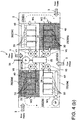
- the membrane separation device 30 installed in any one of the aerobic tanks 20a, 20b, 20c, and 20d is stopped.
- the number of the membrane separation devices 30 to be stopped is set by the processing load. Therefore, two or more membrane separation devices 30 may be stopped at the same time.
- a stop of the membrane separation device 30 means a state in which the aeration device 32 and the auxiliary aeration device 40 are stopped and the membrane permeation is also stopped.
- the aeration is stopped by shutting down corresponding one of the valves V1 to V4, and the membrane permeation is stopped by shutting down corresponding one of the valves V5 to V8.
- the hatched aerobic tank 20c indicates that the membrane separation device 30 therein has been stopped
- the hatched aerobic tank 20a indicates that the membrane separation device 30 therein has been stopped.
- the control unit 60 is configured to control such that, when it determines that one of the membrane separation devices 30 is to be stopped, the membrane separation device subject to a stop is switched in every predetermined time period.
- the membrane separation device 30 in one of the aerobic tanks 20 should be stopped, the membrane separation device 30 to be stopped is switched every cycle or every several cycles of the filtration operation and the relaxation operation described above.
- the switching is synchronized with the cycle of the filtration operation and relaxation operation, the switching can also be performed asynchronously to the cycle of the filtration operation and relaxation operation.
- an operating state as shown in FIG. 3(a) is switched to that of FIG. 3(b) .
- the number of the membrane separation devices 30 to be stopped is not limited to one, but two or more membrane separation devices 30 may be stopped, though at least one of the membrane separation devices 30 needs to be operated.
- the two membrane separation devices 30 can be switched together as a unit, synchronized with the cycle of the filtration operation and relaxation operation. That is, an operation state of FIG. 4 (a) and that of FIG. 4 (b) are alternately switched in such a switching mode.
- the membrane separation device 30 When the membrane separation device 30 is stopped by determining that the processing load would be reduced based on the index as described above, if a specific membrane separation device 30 is stopped for a prolonged period of time, there might be a risk of spoiling the sludge in the corresponding aerobic tank 20.
- a degree of the processing load can be determined based on the quantity of the inflow. If the tank water level is used as the index, the processing load is determined to be low when the tank water level is low.
- the transmembrane pressure of each membrane separation device is adopted as the index, it is determined from a low transmembrane pressure which means that the processing load is low and thus the filtration efficiency is high, that it is not necessary to operate all of the membrane separation devices 30, while it is determined from an increased transmembrane pressure that it is necessary to start operating the membrane separation device 30 which has been stopped.
- T-N or the NH 3 -N concentration of the treated water is used as the index, a degree of denitrification load can be determined, and it is determined from a lower concentration that it is not necessary to operate all the membrane separation devices 30, while it is determined from a higher concentration that it is necessary to start operating the membrane separation device 30 which has been stopped.
- control unit 60 is configured to adjust an injection amount of a flocculant injected into the activated sludge in the biological treatment tank 2 based on the operation status of the membrane separation device 30.
- the activated sludge Since the upper end of the opening 21 of the outflow port of the aerobic tank 20 is submerged and is disposed at a position at or lower than 30 cm from the water surface of the aerobic tank 20, even if the membrane separation device 30 in the corresponding aerobic tank 20 is stopped and the activated sludge is not stirred up, the activated sludge is still securely sent to the anoxic tank on the downstream side.
- the membrane separation device 30 since the concentration of the dissolved oxygen DO in the vicinity of the bottom of the membrane separation device 30 is lower than that in the vicinity of the liquid surface, it also suppresses an increase in the concentration of the dissolved oxygen in the anoxic tank 10 on the downstream side.
- the inflow velocity of the activated sludge is set equal to or smaller than 0.5 m/sec.
- a water level difference between the aerobic tank and the anoxic tank due to the inflow of the activated sludge can be suppressed, whereby uniformity in the aeration of the activated sludge in the aerobic tank is enhanced.
- a cutout 11 is so configured that the inflow velocity of the activated sludge is 0.5 m/sec. or less, and an amount of air supplied to the air lift pump AP is adjusted.
- the control unit 60 described above executes an organic wastewater treatment method which includes dividing and supplying the organic wastewater to the anoxic tank in each biological treatment unit, biologically treating the organic wastewater by repeating a denitrification process in the anoxic tank and a nitrification process in the aerobic tank, discharging the membrane-permeated liquid from the membrane separation device in each biological treatment unit as the treated water, and determining for each biological treatment unit whether to stop the membrane separation device which is operating, or whether to start the membrane separation device which has been stopped, based on at least one of an inflow amount of the organic wastewater, a tank water level, a transmembrane pressure difference of each membrane separation device, a T-N of the treated water, and an NH3-N concentration of the treated water as an index.
- an injection amount of the flocculant injected into the activated sludge in the biological treatment tank is adjusted according to the operation status of the membrane separation device.
- the membrane separation device subject to a stop is switched in every predetermined time period.
- the organic wastewater treatment method is executed such that a membrane cleaning process is sequentially performed for all of the membrane separation devices by injecting a cleaning liquid to the stopped membrane separation device from a secondary side thereof, while a membrane filtration flow rate for the membrane separation devices which have been cleaned is set equal to or smaller than that of the membrane separation devices which have not been cleaned until all of the membrane separation devices have been cleaned.
Landscapes
- Life Sciences & Earth Sciences (AREA)
- Chemical & Material Sciences (AREA)
- Water Supply & Treatment (AREA)
- Hydrology & Water Resources (AREA)
- Engineering & Computer Science (AREA)
- Environmental & Geological Engineering (AREA)
- Microbiology (AREA)
- Biodiversity & Conservation Biology (AREA)
- Organic Chemistry (AREA)
- Health & Medical Sciences (AREA)
- Molecular Biology (AREA)
- Analytical Chemistry (AREA)
- Separation Using Semi-Permeable Membranes (AREA)
- Activated Sludge Processes (AREA)
- Purification Treatments By Anaerobic Or Anaerobic And Aerobic Bacteria Or Animals (AREA)
Applications Claiming Priority (2)
| Application Number | Priority Date | Filing Date | Title |
|---|---|---|---|
| JP2017074763A JP6883459B2 (ja) | 2017-04-04 | 2017-04-04 | 有機性排水処理方法及び有機性排水処理装置 |
| PCT/JP2018/013695 WO2018186299A1 (ja) | 2017-04-04 | 2018-03-30 | 有機性排水処理方法及び有機性排水処理装置 |
Publications (3)
| Publication Number | Publication Date |
|---|---|
| EP3608295A1 true EP3608295A1 (de) | 2020-02-12 |
| EP3608295A4 EP3608295A4 (de) | 2020-03-04 |
| EP3608295B1 EP3608295B1 (de) | 2025-04-30 |
Family
ID=63713038
Family Applications (1)
| Application Number | Title | Priority Date | Filing Date |
|---|---|---|---|
| EP18780388.7A Active EP3608295B1 (de) | 2017-04-04 | 2018-03-30 | Verfahren zur behandlung organischer abwässer und vorrichtung zur behandlung organischer abwässer |
Country Status (6)
| Country | Link |
|---|---|
| US (1) | US10822260B2 (de) |
| EP (1) | EP3608295B1 (de) |
| JP (1) | JP6883459B2 (de) |
| CN (1) | CN110461777A (de) |
| ES (1) | ES3030808T3 (de) |
| WO (1) | WO2018186299A1 (de) |
Families Citing this family (3)
| Publication number | Priority date | Publication date | Assignee | Title |
|---|---|---|---|---|
| JP7208949B2 (ja) * | 2020-05-22 | 2023-01-19 | 水ing株式会社 | アンモニア態窒素含有希釈対象物の希釈処理方法及び希釈処理装置 |
| JP7640443B2 (ja) | 2021-12-07 | 2025-03-05 | 株式会社クボタ | 有機性排水処理装置及び有機性排水処理装置の運転方法 |
| CN116903139A (zh) * | 2023-08-24 | 2023-10-20 | 宇星环保工程有限公司 | 适用污水处理厂改造的多段进水多级ao系统及控制方法 |
Family Cites Families (17)
| Publication number | Priority date | Publication date | Assignee | Title |
|---|---|---|---|---|
| JP2000140886A (ja) * | 1998-11-11 | 2000-05-23 | Kawasaki Steel Corp | 窒素含有排液の処理設備 |
| JP2003024973A (ja) * | 2001-07-16 | 2003-01-28 | Kubota Corp | 膜分離型オキシデーションディッチ |
| JP3958990B2 (ja) * | 2002-03-29 | 2007-08-15 | 住友重機械工業株式会社 | 被処理液供給量調整方法及び凝集沈殿設備 |
| JP2004148146A (ja) * | 2002-10-29 | 2004-05-27 | Suiwa Kogiken:Kk | 排水の処理方法 |
| JP4374885B2 (ja) * | 2003-04-07 | 2009-12-02 | 株式会社日立プラントテクノロジー | 膜分離装置 |
| US7147777B1 (en) * | 2005-05-09 | 2006-12-12 | Eimco Water Technologies Llc | Wastewater treatment system with membrane separators and provision for storm flow conditions |
| KR100675977B1 (ko) * | 2005-06-29 | 2007-01-30 | (주)송림워터테크 | 오폐수 처리방법 및 장치 |
| WO2007044345A2 (en) * | 2005-10-05 | 2007-04-19 | Siemens Water Technologies Corp. | Method and apparatus for treating wastewater |
| JP4584849B2 (ja) * | 2006-02-24 | 2010-11-24 | 株式会社日立製作所 | 凝集剤注入量制御方法及び制御コントローラ |
| US7909995B2 (en) * | 2008-02-20 | 2011-03-22 | Washington State University Research Foundation | Combined nutrient recovery and biogas scrubbing system integrated in series with animal manure anaerobic digester |
| JP2010089079A (ja) * | 2008-09-11 | 2010-04-22 | Toray Ind Inc | 浸漬型膜分離装置の運転方法、および浸漬型膜分離装置 |
| JP4966953B2 (ja) * | 2008-12-12 | 2012-07-04 | 水道機工株式会社 | 多段型膜ろ過システムの運転方法 |
| JP5665307B2 (ja) * | 2009-11-30 | 2015-02-04 | 株式会社クボタ | 有機性排水処理装置および有機性排水処理方法 |
| CN102145969B (zh) * | 2011-05-20 | 2012-05-23 | 中国矿业大学 | 一种多级厌氧好氧并流尾段缺氧活性污泥工艺 |
| JP6027474B2 (ja) * | 2013-03-27 | 2016-11-16 | 株式会社クボタ | 有機性排水処理装置の運転方法及び有機性排水処理装置 |
| JP6158691B2 (ja) * | 2013-11-18 | 2017-07-05 | 株式会社東芝 | 有機排水処理装置、有機排水の処理方法及び有機排水処理装置の制御プログラム |
| JP6532723B2 (ja) * | 2015-03-26 | 2019-06-19 | 株式会社クボタ | 有機性排水の処理方法及びその処理システム |
-
2017
- 2017-04-04 JP JP2017074763A patent/JP6883459B2/ja active Active
-
2018
- 2018-03-30 WO PCT/JP2018/013695 patent/WO2018186299A1/ja not_active Ceased
- 2018-03-30 CN CN201880023055.0A patent/CN110461777A/zh active Pending
- 2018-03-30 EP EP18780388.7A patent/EP3608295B1/de active Active
- 2018-03-30 ES ES18780388T patent/ES3030808T3/es active Active
-
2019
- 2019-10-04 US US16/593,637 patent/US10822260B2/en active Active
Also Published As
| Publication number | Publication date |
|---|---|
| US10822260B2 (en) | 2020-11-03 |
| WO2018186299A1 (ja) | 2018-10-11 |
| JP6883459B2 (ja) | 2021-06-09 |
| EP3608295B1 (de) | 2025-04-30 |
| JP2018176016A (ja) | 2018-11-15 |
| CN110461777A (zh) | 2019-11-15 |
| ES3030808T3 (en) | 2025-07-02 |
| US20200031697A1 (en) | 2020-01-30 |
| EP3608295A4 (de) | 2020-03-04 |
Similar Documents
| Publication | Publication Date | Title |
|---|---|---|
| US11643345B2 (en) | Method for treating organic wastewater, and device for treating organic wastewater | |
| EP2980029B1 (de) | Betriebsverfahren für eine vorrichtung zur behandlung organischer abwässer und vorrichtung zur behandlung organischer abwässer | |
| US10822260B2 (en) | Organic wastewater treatment method and organic wastewater treatment device | |
| KR20200042273A (ko) | 삼분할포기 및 흐름변경방법을 적용한 침지식 멤브레인 결합형 하폐수 고도처리방법 | |
| US20120012524A1 (en) | Membrane bioreactor process | |
| JP6181003B2 (ja) | 膜分離活性汚泥処理装置及びその運転方法 | |
| JPWO2014034836A1 (ja) | 膜分離活性汚泥法の膜面洗浄方法 | |
| KR102596610B1 (ko) | Mbr 공법을 이용한 하폐수 처리 설비 및 이의 운전 방법 | |
| JP6431820B2 (ja) | 活性汚泥処理装置及び活性汚泥処理方法 | |
| EP4445993A1 (de) | Vorrichtung zur behandlung von organischem abwasser und betriebsverfahren für vorrichtung zur behandlung von organischem abwasser | |
| JP2000042586A (ja) | 膜分離合併浄化槽 | |
| JP6475580B2 (ja) | 活性汚泥処理装置 | |
| JP5016827B2 (ja) | 膜分離活性汚泥処理方法 | |
| JP2017113711A (ja) | 有機性排水処理装置および有機性排水処理方法 | |
| JP2001062471A (ja) | 窒素含有汚水の処理装置 | |
| KR100860300B1 (ko) | 간헐포기 연속처리식 막결합형의 하폐수 고도처리장치 및 방법 | |
| KR100740579B1 (ko) | 활성 슬러지 공법을 이용하는 기존의 하수 처리공정으로부터 개선된 고도처리장치 및 방법 | |
| JP2025180027A (ja) | 活性汚泥処理装置、および活性汚泥処理装置の改造方法 | |
| JP2018043214A (ja) | 汚水処理設備及び汚水処理方法 | |
| JPH1099894A (ja) | 汚水処理装置と汚水処理方法 | |
| JP2000084555A (ja) | 膜分離装置を備えた水処理装置の運転方法 |
Legal Events
| Date | Code | Title | Description |
|---|---|---|---|
| STAA | Information on the status of an ep patent application or granted ep patent |
Free format text: STATUS: THE INTERNATIONAL PUBLICATION HAS BEEN MADE |
|
| PUAI | Public reference made under article 153(3) epc to a published international application that has entered the european phase |
Free format text: ORIGINAL CODE: 0009012 |
|
| STAA | Information on the status of an ep patent application or granted ep patent |
Free format text: STATUS: REQUEST FOR EXAMINATION WAS MADE |
|
| 17P | Request for examination filed |
Effective date: 20191031 |
|
| AK | Designated contracting states |
Kind code of ref document: A1 Designated state(s): AL AT BE BG CH CY CZ DE DK EE ES FI FR GB GR HR HU IE IS IT LI LT LU LV MC MK MT NL NO PL PT RO RS SE SI SK SM TR |
|
| AX | Request for extension of the european patent |
Extension state: BA ME |
|
| A4 | Supplementary search report drawn up and despatched |
Effective date: 20200130 |
|
| RIC1 | Information provided on ipc code assigned before grant |
Ipc: C02F 3/30 20060101ALI20200124BHEP Ipc: C02F 3/34 20060101AFI20200124BHEP Ipc: C02F 3/00 20060101ALI20200124BHEP Ipc: C02F 3/12 20060101ALI20200124BHEP Ipc: B01D 21/30 20060101ALI20200124BHEP |
|
| DAV | Request for validation of the european patent (deleted) | ||
| DAX | Request for extension of the european patent (deleted) | ||
| STAA | Information on the status of an ep patent application or granted ep patent |
Free format text: STATUS: EXAMINATION IS IN PROGRESS |
|
| 17Q | First examination report despatched |
Effective date: 20220314 |
|
| GRAP | Despatch of communication of intention to grant a patent |
Free format text: ORIGINAL CODE: EPIDOSNIGR1 |
|
| STAA | Information on the status of an ep patent application or granted ep patent |
Free format text: STATUS: GRANT OF PATENT IS INTENDED |
|
| GRAJ | Information related to disapproval of communication of intention to grant by the applicant or resumption of examination proceedings by the epo deleted |
Free format text: ORIGINAL CODE: EPIDOSDIGR1 |
|
| STAA | Information on the status of an ep patent application or granted ep patent |
Free format text: STATUS: EXAMINATION IS IN PROGRESS |
|
| INTG | Intention to grant announced |
Effective date: 20240925 |
|
| GRAP | Despatch of communication of intention to grant a patent |
Free format text: ORIGINAL CODE: EPIDOSNIGR1 |
|
| STAA | Information on the status of an ep patent application or granted ep patent |
Free format text: STATUS: GRANT OF PATENT IS INTENDED |
|
| INTC | Intention to grant announced (deleted) | ||
| INTG | Intention to grant announced |
Effective date: 20241126 |
|
| GRAS | Grant fee paid |
Free format text: ORIGINAL CODE: EPIDOSNIGR3 |
|
| GRAA | (expected) grant |
Free format text: ORIGINAL CODE: 0009210 |
|
| STAA | Information on the status of an ep patent application or granted ep patent |
Free format text: STATUS: THE PATENT HAS BEEN GRANTED |
|
| AK | Designated contracting states |
Kind code of ref document: B1 Designated state(s): AL AT BE BG CH CY CZ DE DK EE ES FI FR GB GR HR HU IE IS IT LI LT LU LV MC MK MT NL NO PL PT RO RS SE SI SK SM TR |
|
| REG | Reference to a national code |
Ref country code: CH Ref legal event code: EP Ref country code: GB Ref legal event code: FG4D |
|
| REG | Reference to a national code |
Ref country code: DE Ref legal event code: R096 Ref document number: 602018081533 Country of ref document: DE |
|
| REG | Reference to a national code |
Ref country code: IE Ref legal event code: FG4D |
|
| REG | Reference to a national code |
Ref country code: ES Ref legal event code: FG2A Ref document number: 3030808 Country of ref document: ES Kind code of ref document: T3 Effective date: 20250702 |
|
| REG | Reference to a national code |
Ref country code: NL Ref legal event code: MP Effective date: 20250430 |
|
| REG | Reference to a national code |
Ref country code: AT Ref legal event code: MK05 Ref document number: 1789929 Country of ref document: AT Kind code of ref document: T Effective date: 20250430 |
|
| PG25 | Lapsed in a contracting state [announced via postgrant information from national office to epo] |
Ref country code: PT Free format text: LAPSE BECAUSE OF FAILURE TO SUBMIT A TRANSLATION OF THE DESCRIPTION OR TO PAY THE FEE WITHIN THE PRESCRIBED TIME-LIMIT Effective date: 20250901 Ref country code: FI Free format text: LAPSE BECAUSE OF FAILURE TO SUBMIT A TRANSLATION OF THE DESCRIPTION OR TO PAY THE FEE WITHIN THE PRESCRIBED TIME-LIMIT Effective date: 20250430 |
|
| REG | Reference to a national code |
Ref country code: LT Ref legal event code: MG9D |
|
| PG25 | Lapsed in a contracting state [announced via postgrant information from national office to epo] |
Ref country code: GR Free format text: LAPSE BECAUSE OF FAILURE TO SUBMIT A TRANSLATION OF THE DESCRIPTION OR TO PAY THE FEE WITHIN THE PRESCRIBED TIME-LIMIT Effective date: 20250731 Ref country code: NO Free format text: LAPSE BECAUSE OF FAILURE TO SUBMIT A TRANSLATION OF THE DESCRIPTION OR TO PAY THE FEE WITHIN THE PRESCRIBED TIME-LIMIT Effective date: 20250730 |
|
| PG25 | Lapsed in a contracting state [announced via postgrant information from national office to epo] |
Ref country code: NL Free format text: LAPSE BECAUSE OF FAILURE TO SUBMIT A TRANSLATION OF THE DESCRIPTION OR TO PAY THE FEE WITHIN THE PRESCRIBED TIME-LIMIT Effective date: 20250430 Ref country code: PL Free format text: LAPSE BECAUSE OF FAILURE TO SUBMIT A TRANSLATION OF THE DESCRIPTION OR TO PAY THE FEE WITHIN THE PRESCRIBED TIME-LIMIT Effective date: 20250430 |
|
| PG25 | Lapsed in a contracting state [announced via postgrant information from national office to epo] |
Ref country code: BG Free format text: LAPSE BECAUSE OF FAILURE TO SUBMIT A TRANSLATION OF THE DESCRIPTION OR TO PAY THE FEE WITHIN THE PRESCRIBED TIME-LIMIT Effective date: 20250430 |
|
| PG25 | Lapsed in a contracting state [announced via postgrant information from national office to epo] |
Ref country code: HR Free format text: LAPSE BECAUSE OF FAILURE TO SUBMIT A TRANSLATION OF THE DESCRIPTION OR TO PAY THE FEE WITHIN THE PRESCRIBED TIME-LIMIT Effective date: 20250430 |
|
| PG25 | Lapsed in a contracting state [announced via postgrant information from national office to epo] |
Ref country code: AT Free format text: LAPSE BECAUSE OF FAILURE TO SUBMIT A TRANSLATION OF THE DESCRIPTION OR TO PAY THE FEE WITHIN THE PRESCRIBED TIME-LIMIT Effective date: 20250430 |
|
| PG25 | Lapsed in a contracting state [announced via postgrant information from national office to epo] |
Ref country code: RS Free format text: LAPSE BECAUSE OF FAILURE TO SUBMIT A TRANSLATION OF THE DESCRIPTION OR TO PAY THE FEE WITHIN THE PRESCRIBED TIME-LIMIT Effective date: 20250731 |
|
| PG25 | Lapsed in a contracting state [announced via postgrant information from national office to epo] |
Ref country code: IS Free format text: LAPSE BECAUSE OF FAILURE TO SUBMIT A TRANSLATION OF THE DESCRIPTION OR TO PAY THE FEE WITHIN THE PRESCRIBED TIME-LIMIT Effective date: 20250830 |
|
| PG25 | Lapsed in a contracting state [announced via postgrant information from national office to epo] |
Ref country code: LV Free format text: LAPSE BECAUSE OF FAILURE TO SUBMIT A TRANSLATION OF THE DESCRIPTION OR TO PAY THE FEE WITHIN THE PRESCRIBED TIME-LIMIT Effective date: 20250430 |
|
| PG25 | Lapsed in a contracting state [announced via postgrant information from national office to epo] |
Ref country code: SM Free format text: LAPSE BECAUSE OF FAILURE TO SUBMIT A TRANSLATION OF THE DESCRIPTION OR TO PAY THE FEE WITHIN THE PRESCRIBED TIME-LIMIT Effective date: 20250430 Ref country code: DK Free format text: LAPSE BECAUSE OF FAILURE TO SUBMIT A TRANSLATION OF THE DESCRIPTION OR TO PAY THE FEE WITHIN THE PRESCRIBED TIME-LIMIT Effective date: 20250430 |
|
| PG25 | Lapsed in a contracting state [announced via postgrant information from national office to epo] |
Ref country code: CZ Free format text: LAPSE BECAUSE OF FAILURE TO SUBMIT A TRANSLATION OF THE DESCRIPTION OR TO PAY THE FEE WITHIN THE PRESCRIBED TIME-LIMIT Effective date: 20250430 |
|
| PG25 | Lapsed in a contracting state [announced via postgrant information from national office to epo] |
Ref country code: EE Free format text: LAPSE BECAUSE OF FAILURE TO SUBMIT A TRANSLATION OF THE DESCRIPTION OR TO PAY THE FEE WITHIN THE PRESCRIBED TIME-LIMIT Effective date: 20250430 |
|
| PG25 | Lapsed in a contracting state [announced via postgrant information from national office to epo] |
Ref country code: RO Free format text: LAPSE BECAUSE OF FAILURE TO SUBMIT A TRANSLATION OF THE DESCRIPTION OR TO PAY THE FEE WITHIN THE PRESCRIBED TIME-LIMIT Effective date: 20250430 Ref country code: SK Free format text: LAPSE BECAUSE OF FAILURE TO SUBMIT A TRANSLATION OF THE DESCRIPTION OR TO PAY THE FEE WITHIN THE PRESCRIBED TIME-LIMIT Effective date: 20250430 |
|
| REG | Reference to a national code |
Ref country code: DE Ref legal event code: R097 Ref document number: 602018081533 Country of ref document: DE |
|
| PLBE | No opposition filed within time limit |
Free format text: ORIGINAL CODE: 0009261 |
|
| STAA | Information on the status of an ep patent application or granted ep patent |
Free format text: STATUS: NO OPPOSITION FILED WITHIN TIME LIMIT |
|
| REG | Reference to a national code |
Ref country code: CH Ref legal event code: L10 Free format text: ST27 STATUS EVENT CODE: U-0-0-L10-L00 (AS PROVIDED BY THE NATIONAL OFFICE) Effective date: 20260311 |
|
| 26N | No opposition filed |
Effective date: 20260202 |
|
| PGFP | Annual fee paid to national office [announced via postgrant information from national office to epo] |
Ref country code: IT Payment date: 20260220 Year of fee payment: 9 |
|
| PGFP | Annual fee paid to national office [announced via postgrant information from national office to epo] |
Ref country code: FR Payment date: 20260209 Year of fee payment: 9 |